EP4550307A1 - Soundproof heat-dissipating cover - Google Patents
Soundproof heat-dissipating cover Download PDFInfo
- Publication number
- EP4550307A1 EP4550307A1 EP23885850.0A EP23885850A EP4550307A1 EP 4550307 A1 EP4550307 A1 EP 4550307A1 EP 23885850 A EP23885850 A EP 23885850A EP 4550307 A1 EP4550307 A1 EP 4550307A1
- Authority
- EP
- European Patent Office
- Prior art keywords
- heat
- dissipating
- sound
- reinforcing member
- absorbing
- Prior art date
- Legal status (The legal status is an assumption and is not a legal conclusion. Google has not performed a legal analysis and makes no representation as to the accuracy of the status listed.)
- Granted
Links
Images




Classifications
-
- G—PHYSICS
- G10—MUSICAL INSTRUMENTS; ACOUSTICS
- G10K—SOUND-PRODUCING DEVICES; METHODS OR DEVICES FOR PROTECTING AGAINST, OR FOR DAMPING, NOISE OR OTHER ACOUSTIC WAVES IN GENERAL; ACOUSTICS NOT OTHERWISE PROVIDED FOR
- G10K11/00—Methods or devices for transmitting, conducting or directing sound in general; Methods or devices for protecting against, or for damping, noise or other acoustic waves in general
- G10K11/16—Methods or devices for protecting against, or for damping, noise or other acoustic waves in general
- G10K11/162—Selection of materials
-
- B—PERFORMING OPERATIONS; TRANSPORTING
- B60—VEHICLES IN GENERAL
- B60R—VEHICLES, VEHICLE FITTINGS, OR VEHICLE PARTS, NOT OTHERWISE PROVIDED FOR
- B60R13/00—Elements for body-finishing, identifying, or decorating; Arrangements or adaptations for advertising purposes
- B60R13/08—Insulating elements, e.g. for sound insulation
-
- F—MECHANICAL ENGINEERING; LIGHTING; HEATING; WEAPONS; BLASTING
- F02—COMBUSTION ENGINES; HOT-GAS OR COMBUSTION-PRODUCT ENGINE PLANTS
- F02B—INTERNAL-COMBUSTION PISTON ENGINES; COMBUSTION ENGINES IN GENERAL
- F02B77/00—Component parts, details or accessories, not otherwise provided for
- F02B77/11—Thermal or acoustic insulation
- F02B77/13—Acoustic insulation
-
- G—PHYSICS
- G10—MUSICAL INSTRUMENTS; ACOUSTICS
- G10K—SOUND-PRODUCING DEVICES; METHODS OR DEVICES FOR PROTECTING AGAINST, OR FOR DAMPING, NOISE OR OTHER ACOUSTIC WAVES IN GENERAL; ACOUSTICS NOT OTHERWISE PROVIDED FOR
- G10K11/00—Methods or devices for transmitting, conducting or directing sound in general; Methods or devices for protecting against, or for damping, noise or other acoustic waves in general
- G10K11/16—Methods or devices for protecting against, or for damping, noise or other acoustic waves in general
Definitions
- Patent Document 1 describes a soundproof cover covering a target object.
- the soundproof cover includes a sound-absorbing sheet that is formed of a sound-absorbing material into a surface shape and covers a surface of the target object, and a reinforcing member that positions the sound-absorbing sheet with respect to the target object.
- the reinforcing member positions the sound-absorbing sheet with respect to the target object in a state exposing at least a part of the sound-absorbing sheet. Accordingly, in the case where the target object generates heat, the heat generated from the target object is transmitted to the sound-absorbing sheet, and further dissipated to outside from portions of the sound-absorbing sheet exposed to outside. Accordingly, a heat dissipation performance for the target object can be improved.
- Patent Document 1 International Publication No. 2022/124113
- the portions of the sound-absorbing sheet exposed from the reinforcing member may sag downward due to gravity, and a gap may form between the target object and the sound-absorbing sheet.
- heat may become trapped on the target object due to an air layer formed at the gap between the target object and the sound-absorbing sheet, and the heat dissipation performance for the target object may deteriorate.
- the present disclosure has been made in view of such background and aims to provide a soundproof heat-dissipating cover with an improved heat dissipation performance.
- An aspect of the present disclosure is a soundproof heat-dissipating cover covering a target object.
- the soundproof heat-dissipating cover includes a sound-absorbing heat-dissipating sheet and a reinforcing member.
- the sound-absorbing heat-dissipating sheet is formed of a first sound-absorbing material into a surface shape, and includes a covering surface covering a surface of the target object and a heat-dissipating surface on a side opposite to the covering surface.
- the reinforcing member is formed of a material having a hardness higher than the first sound-absorbing material, and covers the sound-absorbing heat-dissipating sheet from a heat-dissipating surface side of the sound-absorbing heat-dissipating sheet.
- the sound-absorbing heat-dissipating sheet further includes a pair of first mounting parts formed at positions near both ends in a first direction along the covering surface, and a heat-dissipating region formed between the pair of first mounting parts.
- the heat-dissipating surface in the heat-dissipating region of the sound-absorbing heat-dissipating sheet is formed with a plurality of ridges arranged side by side at an interval.
- the reinforcing member includes a pair of second mounting parts and a bridging part.
- the pair of second mounting parts are formed at positions near both ends in the first direction and are respectively mounted to the pair of first mounting parts.
- the bridging part bridges between the pair of second mounting parts and has a plurality of through-holes.
- the plurality of ridges of the sound-absorbing heat-dissipating sheet are supported by the bridging part of the reinforcing member. Accordingly, deformation of the sound-absorbing heat-dissipating sheet into a protruding shape in a direction from the covering surface toward the heat-dissipating surface is suppressed.
- the soundproof heat-dissipating cover 1 has a function of covering a target object 2 to suppress transmission of sound generated by the target object 2 to outside, and a function of dissipating heat of the target object 2 to outside.
- the target object 2 is, for example, a power source of a vehicle.
- the power source may be a drive motor of a vehicle, a drive engine of a vehicle, etc.
- FIG. 1 shows a case where the target object 2 is a drive motor of a vehicle.
- the drive motor in FIG. 1 is exemplified as having a cylindrical outer circumferential surface.
- the outer circumferential surface of the drive motor is not limited to a cylindrical surface, and may also be formed with protrusions and recesses as appropriate.
- the drive motor is disposed such that a rotational axis of the drive motor is in line with a left-right direction of the vehicle.
- a left side of FIG. 1 represents a vehicle front side
- a right side of FIG. 1 represents a vehicle rear side.
- a vehicle front surface of the drive motor is a region capable of directly receiving an airflow due to vehicle traveling.
- both upper and lower lateral surfaces of the drive motor are also capable of receiving an airflow flowing from the front side to the rear side due to vehicle traveling.
- a vehicle rear surface of the drive motor is a region that does not directly receive an airflow during vehicle traveling.
- a lower surface of the drive motor is a surface capable of directly receiving an airflow due to natural convection.
- both front and rear lateral surfaces of the drive motor are also capable of receiving an airflow circulating from the lower side to the upper side due to natural convection.
- An upper surface of the drive motor is a region that does not directly receive an airflow due to natural convection.
- At least one of the lateral surfaces in a circumferential direction of the drive motor is a surface capable of receiving an airflow.
- the drive motor may also be configured to be disposed such that the rotational axis of the drive motor is in line with a front-rear direction of the vehicle.
- both upper and lower lateral surfaces and both left and right lateral surfaces of the drive motor are regions capable of directly receiving an airflow due to vehicle traveling.
- the soundproof heat-dissipating cover 1 covers the surface of the target object 2.
- the soundproof heat-dissipating cover 1 covers an outer circumferential surface of the drive motor.
- the soundproof heat-dissipating cover 1 covers an entire circumference of the outer circumferential surface of the target object 2, but a portion that is not covered may also be provided.
- four soundproof heat-dissipating covers 1 cover the outer circumferential surface of the target object 2.
- the four soundproof heat-dissipating covers 1 cover an upper surface, a lower surface, a front surface, and a rear surface of the target object 2.
- the number of soundproof heat-dissipating covers 1 may also be 1 to 3, or 5 or more.
- the soundproof heat-dissipating cover 1 includes a sound-absorbing heat-dissipating sheet 3 and a reinforcing member 4.
- the sound-absorbing heat-dissipating sheet 3 is formed of a first sound-absorbing material having sound-absorbing properties into a surface shape, and covers the surface of the target object 2. Thus, a soundproofing effect can be obtained by the sound-absorbing heat-dissipating sheet 3.
- the sound-absorbing heat-dissipating sheet 3 may also be formed into a shape corresponding to the surface shape of the target object 2 in advance.
- the sound-absorbing heat-dissipating sheet 3 may also be formed of a deformable material into a planar shape, and mounted to the surface of the target object 2 while being deformed.
- the sound-absorbing heat-dissipating sheet 3 has heat-dissipating properties in addition to sound-absorbing properties.
- the sound-absorbing heat-dissipating sheet 3 includes a covering surface 10 that covers the surface of the target object 2, and a heat-dissipating surface 11 on the opposite side of the covering surface 10.
- a first sound-absorbing material constituting the sound-absorbing heat-dissipating sheet 3 is preferably formed of a material with excellent sound-absorbing properties such as a foamed resin.
- the foamed resin applicable may include a urethane foam, an acrylic foam, a silicone foam, a styrene foam, foamed olefin (foamed PP, foamed PE), foamed PVC, foamed EVA, foamed PA, etc.
- An Asker C hardness of the foamed resin of the sound-absorbing heat-dissipating sheet 3 is 1 to 60 degrees.
- the sound-absorbing heat-dissipating sheet 3 may also be formed of a non-foamed resin having sound-absorbing properties, or may also be formed of a metal.
- the non-foamed resin applicable may include a polyamide resin, an olefin resin, a styrene resin, a urethane resin, a silicone resin, an acrylic resin, a polyvinyl chloride resin, a polyethylene resin, a polyethylene terephthalate resin, a polycarbonate resin, a polypropylene resin, an ABS resin, an EVA resin, a carbon fiber plastic (FRP, CFRP), etc.
- the metal applicable may include iron, aluminum, stainless steel, copper, and alloys thereof. However, a foamed resin with excellent sound-absorbing properties is preferable.
- the sound-absorbing heat-dissipating sheet 3 may be formed of a foamed resin containing a heat-conductive material.
- the heat-conductive material may be extended from the covering surface 10 of the sound-absorbing heat-dissipating sheet 3 toward the heat-dissipating surface 11.
- the heat-conductive filler is arranged from the covering surface 10 of the sound-absorbing heat-dissipating sheet 3 toward the heat-dissipating surface 11.
- a filling amount of the heat-conductive material may vary depending on the position of the sound-absorbing heat-dissipating sheet 3. For example, since the vehicle rear surface is more difficult to cool than the vehicle front surface, the filling amount of the heat-conductive material on the vehicle rear surface may be increased compared to the vehicle front surface.
- the filling amount refers to a filling amount per unit area in a plane direction of the sound-absorbing heat-dissipating sheet 3.
- the heat-conductive material may be insert-molded to extend from the covering surface 10 of the sound-absorbing heat-dissipating sheet 3 toward the heat-dissipating surface 11.
- the reinforcing member 4 positions the sound-absorbing heat-dissipating sheet 3 with respect to the target object 2.
- the reinforcing member 4 is formed separately from the sound-absorbing heat-dissipating sheet 3, and is disposed on the heat-dissipating surface 11 side of the sound-absorbing heat-dissipating sheet 3 such that the sound-absorbing heat-dissipating sheet 3 is interposed between the reinforcing member 4 and the target object 2.
- the reinforcing member 4 may be fixed to the target object 2 by bolts 5.
- the sound-absorbing heat-dissipating sheet 3 has first insertion holes 12 that are formed to penetrate the sound-absorbing heat-dissipating sheet 3 and into which the bolts 5 are inserted (see FIG. 3 ).
- the reinforcing member 4 has second insertion holes 20 that are formed to penetrate the reinforcing member 4 and into which the bolts 5 are inserted (see FIG. 4 ).
- the method of fixing the reinforcing member 4 and the target object 2 is not limited to bolt fastening, and for example, the reinforcing member 4 may also be configured to engage with engaging claws provided at the target object 2.
- the first insertion holes 12 and the second insertion holes 20 are omitted.
- the reinforcing member 4 is formed of a material with a hardness higher than the sound-absorbing heat-dissipating sheet 3.
- the sound-absorbing heat-dissipating sheet 3 is formed of, for example, a foamed resin into a surface shape.
- An Asker C hardness of the foamed resin of the reinforcing member 4 is 60 to 99 degrees.
- the reinforcing member 4 is formed of a material with a mass per unit volume (hereinafter referred to as a "unit mass") greater than the sound-absorbing heat-dissipating sheet 3. As described above, to enable the reinforcing member 4 to exhibit a reinforcing function, the reinforcing member 4 is consequently formed of a material with a unit mass greater than the sound-absorbing heat-dissipating sheet 3.
- the reinforcing member 4 may also be configured to be formed of a second sound-absorbing material having sound-absorbing properties.
- the second sound-absorbing material may be formed of a material with excellent sound-absorbing properties such as a foamed resin.
- the foamed resin applicable to the reinforcing member 4 is different from the foamed resin applicable to the sound-absorbing heat-dissipating sheet 3.
- examples of the foamed resin applicable to the reinforcing member 4 may include a urethane foam, an acrylic foam, a silicone foam, a styrene foam, foamed olefin (foamed PP, foamed PE), foamed PVC, foamed EVA, foamed PA, etc.
- the urethane foam is applied to the sound-absorbing heat-dissipating sheet 3 and the reinforcing member 4, the urethane foams of the two are of different types.
- the reinforcing member 4 With the second sound-absorbing material, the soundproofing properties of the soundproof heat-dissipating cover 1 can be improved.
- the reinforcing member 4 may also include a material different from the second sound-absorbing material, such as a foamed rubber, a non-foamed resin, or a metal.
- a foamed rubber such as a foamed rubber, a non-foamed resin, or a metal.
- the foamed rubber applicable may include foamed EPDM, foamed CR, foamed NBR/PVC, foamed ACM, etc.
- examples of the non-foamed resin applicable may include a polyamide resin, an olefin resin, a styrene resin, a urethane resin, a silicone resin, an acrylic resin, a polyvinyl chloride resin, a polyethylene resin, a polyethylene terephthalate resin, a polycarbonate resin, a polypropylene resin, an ABS resin, an EVA resin, a carbon fiber plastic (FRP, CFRP), etc.
- examples of the metal applicable may include iron, aluminum, stainless steel, copper, and alloys thereof.
- the reinforcing member is formed of a rubber, a resin, or a metal with a hardness higher than a foamed resin. However, from the perspective of weight reduction, a foamed resin is preferable.
- the reinforcing member 4 is not disposed to cover the entire surface of the sound-absorbing heat-dissipating sheet 3, and is disposed in a state of exposing at least a part of the sound-absorbing heat-dissipating sheet 3.
- the sound-absorbing heat-dissipating sheet 3 has heat-dissipating properties in addition to sound-absorbing properties.
- the reinforcing member 4 may be mounted to the outer circumferential surface of the target object 2 while being deformed to conform to the shape of the outer circumferential surface of the target object 2. Further, in the case where the reinforcing member 4 has a high hardness and is thus difficult to deflect and deform, the reinforcing member 4 may be formed in advance to conform to the shape of the outer circumferential surface of the target object 2. Accordingly, the reinforcing member 4 can be easily mounted to the outer circumferential surface of the target object 2.
- FIG. 1 A detailed configuration of the soundproof heat-dissipating cover 1 will be described with reference to FIG. 1 to FIG. 8 .
- the soundproof heat-dissipating cover 1 is formed into a shape corresponding to the surface shape of the target object 2.
- FIG. 2 to FIG. 8 show the soundproof heat-dissipating cover 1 in a state expanded into a planar shape, and the following description will refer to these figures.
- the soundproof heat-dissipating cover 1 includes a sound-absorbing heat-dissipating sheet 3 and a reinforcing member 4.
- the sound-absorbing heat-dissipating sheet 3 and the reinforcing member 4 will be described in detail below.
- the sound-absorbing heat-dissipating sheet 3 is composed of one sheet only.
- the sound-absorbing heat-dissipating sheet 3 may also be composed of a plurality of divide bodies formed separately.
- the soundproof heat-dissipating cover 1 is formed into a substantially rectangular shape in a plan view.
- the shape of the soundproof heat-dissipating cover 1 is not particularly limited and may be formed into any shape.
- the sound-absorbing heat-dissipating sheet 3 is formed into a substantially rectangular shape in a plan view.
- the sound-absorbing heat-dissipating sheet 3 is formed into a surface shape as a whole.
- the sound-absorbing heat-dissipating sheet 3 includes a pair of first mounting parts 13 formed at positions near both ends in the axial direction (an example of a first direction) of the target object 2, and a heat-dissipating region 14 formed between the pair of first mounting parts 13.
- a plurality of ridges 15 are formed protruding outward on the heat-dissipating surface 11 of the heat-dissipating region 14.
- the plurality of ridges 15 are formed to extend in a plane direction of the sound-absorbing heat-dissipating sheet 3. Specifically, with the sound-absorbing heat-dissipating sheet 3 mounted to the target object 2, the plurality of ridges 15 are formed extending in a straight line shape along the circumferential direction of the outer circumferential surface of the target object 2.
- the plurality of ridges 15 are arranged side by side at an interval in the axial direction of the target object 2 on the heat-dissipating surface 11 of the heat-dissipating region 14.
- the plurality of ridges 15 are formed to be arranged side by side at an equal interval.
- the shape of the plurality of ridges 15 may also be a wave shape in a plan view.
- the plurality of ridges 15 may also be formed to extend in the axial direction of the outer circumferential surface of the target object 2, or may also be formed into a shape that extends in a direction inclined with respect to the circumferential direction and the axial direction of the outer circumferential surface of the target object 2.
- the heat-conductive material may be extended continuously in a surface normal direction of the sound-absorbing heat-dissipating sheet 3, from the covering surface 10 of the sound-absorbing heat-dissipating sheet 3 to a tip of the ridge 15. Accordingly, by continuously disposing the heat-conductive material in a range from the surface of the target object 2 to the tip of the ridge 15, a high heat dissipation performance can be exhibited.
- the heat-conductive material of this case is preferably an electrically conductive filler.
- the heat-conductive material may be extended continuously in an extending direction of the ridge 15 on a tip side of the ridge 15. Accordingly, by continuously disposing the heat-conductive material in a range from one end side to the other end side in the extending direction of the ridge 15, a high heat dissipation performance can also be exhibited in the plane direction.
- the heat-conductive material applicable in this case may include a metal foil such as copper, stainless steel, steel, or aluminum, a metal film such as an aluminum-deposited film, an electrically conductive filler, a heat-conductive resin film, etc.
- a metal foil or a metal film and a resin film may also be laminated.
- the heat-conductive material may also be provided only in specific regions of the plurality of ridges 15 or provided at specific ridges 15 only, and may also be disposed on an outer surface on a tip side or a lateral surface of the ridge 15.
- the sound-absorbing heat-dissipating sheet 3 may be configured as follows.
- the heat-dissipating surface 11 side of the sound-absorbing heat-dissipating sheet 3 may be in a closed-cell state in which cells of the foamed resin are closed, and the covering surface 10 side may be in an open-cell state in which the cells of the foamed resin are open.
- the heat-dissipating surface 11 side in the closed-cell state a pressure loss during circulation of a fluid such as air can be suppressed, so the heat dissipation performance can be enhanced.
- the covering surface 10 side in the open-cell state a sound absorption performance can be enhanced. In other words, with the above configuration, the sound absorption performance and the heat dissipation performance can be improved.
- the reinforcing member 4 is composed of one component only.
- the reinforcing member 4 may also be composed of a plurality of divided bodies.
- the reinforcing member 4 is formed into a substantially rectangular shape in a plan view.
- the reinforcing member 4 is formed in an approximately same size as the sound-absorbing heat-dissipating sheet 3 in a plan view.
- the reinforcing member 4 includes a pair of second mounting parts 21 formed at positions near both ends in the axial direction of the target object 2, and a bridging part 22 that bridges between the pair of second mounting parts 21.
- the pair of second mounting parts 21 are configured to be respectively mounted to the pair of first mounting parts 13 of the sound-absorbing heat-dissipating sheet 3.
- the pair of second mounting parts 21 have mounting surfaces 24 that are opposed to the pair of first mounting parts 13 and are mounted to the pair of first mounting parts 13 by a conventional means such as an adhesive or a double-sided tape 23.
- the second mounting part 21 is mounted to the first mounting part 13 by a double-sided tape 23.
- a width dimension of the pair of second mounting parts 21 is smaller than a width dimension of the pair of first mounting parts 13.
- Second insertion holes 20 penetrating the second mounting parts 21 are formed at the pair of second mounting parts 21. As described above, the second insertion holes 20 are configured for the bolts 5 to insert therein.
- the bridging part 22 includes an accommodating recess 25 formed into a recess shape in a direction away from the sound-absorbing heat-dissipating sheet, on a surface on a side opposed to the sound-absorbing heat-dissipating sheet 3.
- the accommodating recess 25 of the reinforcing member is configured to accommodate the heat-dissipating region 14 of the sound-absorbing heat-dissipating sheet 3.
- the second mounting part 21 and a bottom wall 26 of the accommodating recess 25 are connected by an inclined wall 27 that expands to the second mounting part 21 side.
- the bottom wall 26 of the accommodating recess 25 has an inner surface 28 opposed to the sound-absorbing heat-dissipating sheet 3, and an outer surface 29 on the opposite side of the inner surface 28.
- Ventper holes 30 are formed on both lateral surfaces of the bridging part 22 that intersect with the circumferential direction of the target object 2 to allow air to circulate with respect to the heat-dissipating region 14 of the sound-absorbing heat-dissipating sheet 3.
- air since air is capable of circulating along the circumferential direction of the target object 2, air is capable of flowing into the reinforcing member 4 from the ventilation holes 30 and flowing out to outside.
- the plurality of ridges 15 of the sound-absorbing heat-dissipating sheet 3 are exposed at the ventilation holes 30.
- the air flowing into the reinforcing member 4 from the ventilation holes 30 and flowing out to outside is capable of contacting the plurality of ridges 15.
- the heat dissipation performance of the soundproof heat-dissipating cover 1 is improved.
- the plurality of ridges 15 are formed to extend in a straight line shape, circulation of air is not obstructed. Accordingly, the heat dissipation performance of the soundproof heat-dissipating cover 1 can be improved.
- obstruction to circulation of air can be suppressed.
- the bridging part 22 includes a plurality of through-holes 31 that penetrate the bridging part 22.
- the plurality of through-holes 31 are formed into an elongated slit shape extending in a direction in which the plurality of ridges 15 of the sound-absorbing heat-dissipating sheet 3 are arranged side by side.
- the plurality of through-holes 31 are formed to be arranged side by side at an interval in the extending direction of the plurality of ridges 15.
- the direction in which the plurality of through-holes 31 extend is orthogonal to the direction in which the plurality of ridges 15 extend.
- the direction in which the plurality of through-holes 31 extend and the direction in which the plurality of ridges 15 extend may also be configured to be inclined and intersect with each other.
- the shape of the plurality of through-holes 31 is described as follows: the plurality of through-holes 31 are formed into an elongated slit shape extending in the axial direction of the target object 2, and are formed to be arranged side by side at an interval along the circumferential direction of the outer surface 29 of the target object 2.
- the plurality of through-holes 31 are of the same shape and the same size. Further, the plurality of through-holes 31 are arranged side by side at an equal interval. However, the shape and the size of the plurality of through-holes 31 may also differ from each another, and the intervals between the plurality of through-holes 31 may also differ from each other.
- a protrusion height dimension T1 of the ridge 15 protruding on the heat-dissipating surface 11 of the sound-absorbing heat-dissipating sheet 3 is set to be larger than a height dimension T2 between the mounting surface 24 of the second mounting part 21 and the inner surface 28 of the bridging part 22 of the reinforcing member 4.
- the protrusion height dimension T1 of the ridge 15 protruding on the heat-dissipating surface 11 of the sound-absorbing heat-dissipating sheet 3 may also be set to be equal to the height dimension T2 between the mounting surface 24 of the second mounting part 21 and the inner surface 28 of the bridging part 22 of the reinforcing member 4.
- the relative positional relationship between the sound-absorbing heat-dissipating sheet 3 and the reinforcing member 4 is not particularly limited.
- the protrusion height dimension T1 of the ridge 15 in the state before the reinforcing member 4 is mounted to the sound-absorbing heat-dissipating sheet 3 is set to be larger than the height dimension T2 between the mounting surface 24 of the second mounting part 21 and the inner surface 28 of the bridging part 22 of the reinforcing member 4.
- the plurality of ridges 15 of the sound-absorbing heat-dissipating sheet 3 abutting against the bridging part 22 of the reinforcing member 4, the plurality of ridges 15 of the sound-absorbing heat-dissipating sheet 3 are supported by the bridging part 22 of the reinforcing member 4. Accordingly, deformation of the sound-absorbing heat-dissipating sheet 3 into a protruding shape in a direction from the covering surface 10 toward the heat-dissipating surface 11 is suppressed.
- the sound-absorbing heat-dissipating sheet 3 is pressed against the target object 2. Accordingly, adhesion between the sound-absorbing heat-dissipating sheet 3 and the target object 2 is improved. As a result, the heat dissipation performance of the soundproof heat-dissipating cover 1 is further improved.
- the covering surface 10 of the sound-absorbing heat-dissipating sheet 3 includes a bulging part 16 that bulges to the side opposite to the reinforcing member 4.
- the entire covering surface 10 in the heat-dissipating region 14 of the sound-absorbing heat-dissipating sheet 3 forms the bulging part 16.
- the bulging part 16 includes the heat-conductive material described above.
- a part of the covering surface 10 of the sound-absorbing heat-dissipating sheet 3 bulges, and it is also possible that the covering surface 10 of the sound-absorbing heat-dissipating sheet 3 does not include a bulging part 16.
- the covering surface 10 of the sound-absorbing heat-dissipating sheet 3 covers the surface of the target object.
- the bulging part 16 bulging on the covering surface 10 of the sound-absorbing heat-dissipating sheet 3 reliably contacts the target object 2 and is compressed by the target object 2. Accordingly, since adhesion between the sound-absorbing heat-dissipating sheet 3 and the target object 2 is improved, the heat dissipation performance of the soundproof heat-dissipating cover 1 is improved.
- the portion of the target object 2 to which the soundproof heat-dissipating cover 1 is mounted is not particularly limited.
- the bulging part 16 being defined on the entire covering surface 10 in the heat-dissipating region 14, since adhesion between the sound-absorbing heat-dissipating sheet 3 and the target object 2 is improved over the entire covering surface 10 in the heat-dissipating region 14, the heat dissipation performance of the soundproof heat-dissipating cover 1 is improved.
- the heat-conductive material in the bulging part 16, since it becomes possible to quickly transfer heat emitted by the target object 2 to the sound-absorbing heat-dissipating sheet 3, the heat dissipation performance of the soundproof heat-dissipating cover 1 is improved.
- a soundproof heat-dissipating cover 41 of Embodiment 2 will be described.
- a reinforcing member 42 of the soundproof heat-dissipating cover 41 in this embodiment has fitting recesses 43 on the inner surface 28 of the bridging part 22.
- the fitting recesses 43 are formed as depressed at positions opposed to the tips of the plurality of ridges 15 of the sound-absorbing heat-dissipating sheet 3.
- the fitting recesses 43 are formed extending along the circumferential direction of the target object 2.
- An opening of the fitting recess 43 is formed in a size allowing the tip of the ridge 15 to fit therein.
- the tip of the ridge 15 is configured to fit into the fitting recess 43. Accordingly, deflection deformation of the ridge 15 due to gravity or heat of the target object 2 is suppressed. As a result, since formation of a gap between the ridge 15 of the sound-absorbing heat-dissipating sheet 3 and the bridging part 22 of the reinforcing member 42 is suppressed, the heat dissipation performance of the soundproof heat-dissipating cover 41 can be improved.
- reference signs identical to the reference signs used in previous embodiments represent similar components as in the previous embodiments unless otherwise specified.
- a soundproof heat-dissipating cover 51 of Embodiment 3 will be described.
- a first mounting part 53 provided at a sound-absorbing heat-dissipating sheet 52 in this embodiment is formed protruding in the protruding direction of the ridge 15.
- a protrusion height dimension T3 of the first mounting part 53 is set to be larger than the protrusion height dimension T1 of the ridge 15. Accordingly, a step is formed between the first mounting part 53 and the heat-dissipating region 14 in the protruding direction of the ridge 15.
- a reinforcing member 54 in this embodiment is formed into a flat plate shape.
- a step is not formed between a pair of second mounting parts 55 and a portion other than the pair of second mounting parts 55 on the inner surface 28 of the reinforcing member 54.
- a space is formed by the protrusion height dimension T3 of the first mounting part 53 between the heat-dissipating region 14 of the sound-absorbing heat-dissipating sheet 52 and the bridging part 56 of the reinforcing member 54.
- This space is configured to accommodate the heat-dissipating region 14 and the plurality of ridges 15 of the sound-absorbing heat-dissipating sheet 52.
- the protrusion height dimension T3 of the first mounting part 53 may also be set to be smaller than the protrusion height dimension T1 of the ridge 15. In that case, the plurality of ridges 15 are accommodated in the space in a compressed state.
- a soundproof heat-dissipating cover 61 of Embodiment 4 will be described.
- a compressing protrusion 63 protruding toward the sound-absorbing heat-dissipating sheet 3 is formed on an inner surface 28 of a bridging part 22 of a reinforcing member 62 of the soundproof heat-dissipating cover 61.
- the compressing protrusion 63 may be formed at at least a part of the inner surface 28 of the bridging part 22. However, the entire inner surface 28 of the bridging part 22 may also serve as the compressing protrusion 63 with the entire inner surface 28 of the bridging part 22 protruding toward the sound-absorbing heat-dissipating sheet 3. Since the plurality of ridges 15 of the sound-absorbing heat-dissipating sheet 3 are compressed by the compressing protrusion 63, the heat dissipation performance of the soundproof heat-dissipating cover 61 is further improved.
- a bulging part 16 is formed on the covering surface 10 of the sound-absorbing heat-dissipating sheet 3. Furthermore, with the ridges 15 compressed by the compressing protrusion 63, an additional bulging part 64 protruding further from the bulging part 16 is formed on the covering surface 10 of the sound-absorbing heat-dissipating sheet 3. The additional bulging part 64 is formed at a position that overlaps with the compressing protrusion 63 of the bridging part 22 in the protruding direction of the ridge 15.
- the portion at which the additional bulging part 64 is formed is more strongly compressed by the target object 2. Accordingly, since formation of a gap between the sound-absorbing heat-dissipating sheet 3 and the target object is suppressed, the heat dissipation performance of the soundproof heat-dissipating cover 61 is further improved. This is particularly effective in the case where local high-temperature portions are present on the target object 2.
- a soundproof heat-dissipating cover 71 of Embodiment 5 will be described.
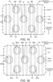
- a plurality of through-holes 72 with a circular inner shape are formed at the bridging part 22.
- the plurality of through-holes 72 are arranged side by side at an interval along the direction in which the plurality of ridges 15 extend, and are arranged side by side at an interval along the direction in which the plurality of ridges 15 are arranged.
- a part of the ridge 15 is exposed from each through-hole 72.
- heat generated by the target object 2 is transferred to the sound-absorbing heat-dissipating sheet 3, is then conducted to the ridge 15, and is dissipated to outside through the through-hole 72 from the ridge 15. Accordingly, the heat dissipation performance of the soundproof heat-dissipating cover 71 can be improved.
- a portion of the bridging part 22 at which the through-holes 72 are not formed abuts against the tips of the plurality of ridges 15. Accordingly, deformation of the sound-absorbing heat-dissipating sheet 3 away from the surface of the target object 2 is suppressed. As a result, since formation of a gap between the sound-absorbing heat-dissipating sheet 3 and the target object 2 is suppressed, the heat dissipation performance of the soundproof heat-dissipating cover 71 can be improved.
- the plurality of through-holes 72 may also be configured to be disposed along only one of the extending direction of the ridge 15 and the arrangement direction of the ridges 15, and not along the other direction. Further, the plurality of through-holes 72 may also be disposed randomly, without being arranged along either of the extending direction of the ridge 15 and the arrangement direction of the ridges 15.
- a soundproof heat-dissipating cover 81 of Embodiment 6 will be described.
- a plurality of through-holes 72 with a circular inner shape are disposed in a staggered pattern at the bridging part 22.
- a portion of the bridging part 22 at which the plurality of through-holes 72 disposed in a staggered pattern are not formed defines a shape in which elongated strip-shaped portions intersect obliquely with both of the extending direction of the plurality of ridges 15 and the arrangement direction of the plurality of ridges 15. Accordingly, since the plurality of ridges 15 can be evenly supported without bias, deformation of the sound-absorbing heat-dissipating sheet 3 in a direction away from the target object 2 can be further suppressed. As a result, the heat dissipation performance of the soundproof heat-dissipating cover 81 can be improved.
- FIG. 16 illustrates a modification example of Embodiment 6.
- an inner shape of a plurality of through-holes 82a is formed into a hexagon.
- the inner shape of the plurality of through-holes 82a is not limited to a circle or a hexagon, and may also be a polygon such as a triangle, a square, a pentagon, etc., or may also be an elliptical shape, and any shape may be selected as appropriate.
- the shape of the plurality of through-holes 82a may be configured such that sizes of the plurality of through-holes 82a are different from each other. For example, in the case where portions prone to becoming locally high-temperature are present on the target object 2, by configuring the size of the through-holes 82a corresponding to the portions prone to becoming high-temperature to be larger than other portions, the heat dissipation performance of the soundproof heat-dissipating cover 81 can be improved.
Landscapes
- Engineering & Computer Science (AREA)
- Physics & Mathematics (AREA)
- Acoustics & Sound (AREA)
- Mechanical Engineering (AREA)
- Multimedia (AREA)
- Chemical & Material Sciences (AREA)
- Combustion & Propulsion (AREA)
- General Engineering & Computer Science (AREA)
- Vehicle Interior And Exterior Ornaments, Soundproofing, And Insulation (AREA)
- Soundproofing, Sound Blocking, And Sound Damping (AREA)
- Cooling Or The Like Of Electrical Apparatus (AREA)
Abstract
Description
- The present disclosure relates to a soundproof heat-dissipating cover.
- As described in
Patent Document 1, it has been known to mount a soundproof cover to a drive source of a vehicle.Patent Document 1 describes a soundproof cover covering a target object. The soundproof cover includes a sound-absorbing sheet that is formed of a sound-absorbing material into a surface shape and covers a surface of the target object, and a reinforcing member that positions the sound-absorbing sheet with respect to the target object. - The reinforcing member positions the sound-absorbing sheet with respect to the target object in a state exposing at least a part of the sound-absorbing sheet. Accordingly, in the case where the target object generates heat, the heat generated from the target object is transmitted to the sound-absorbing sheet, and further dissipated to outside from portions of the sound-absorbing sheet exposed to outside. Accordingly, a heat dissipation performance for the target object can be improved.
- Patent Document 1: International Publication No.
2022/124113 - According to the above art, depending on conditions of use, such as the case of mounting the soundproof cover to a large target object from below, the portions of the sound-absorbing sheet exposed from the reinforcing member may sag downward due to gravity, and a gap may form between the target object and the sound-absorbing sheet. As a result, heat may become trapped on the target object due to an air layer formed at the gap between the target object and the sound-absorbing sheet, and the heat dissipation performance for the target object may deteriorate.
- The present disclosure has been made in view of such background and aims to provide a soundproof heat-dissipating cover with an improved heat dissipation performance.
- An aspect of the present disclosure is a soundproof heat-dissipating cover covering a target object. The soundproof heat-dissipating cover includes a sound-absorbing heat-dissipating sheet and a reinforcing member. The sound-absorbing heat-dissipating sheet is formed of a first sound-absorbing material into a surface shape, and includes a covering surface covering a surface of the target object and a heat-dissipating surface on a side opposite to the covering surface. The reinforcing member is formed of a material having a hardness higher than the first sound-absorbing material, and covers the sound-absorbing heat-dissipating sheet from a heat-dissipating surface side of the sound-absorbing heat-dissipating sheet. The sound-absorbing heat-dissipating sheet further includes a pair of first mounting parts formed at positions near both ends in a first direction along the covering surface, and a heat-dissipating region formed between the pair of first mounting parts. The heat-dissipating surface in the heat-dissipating region of the sound-absorbing heat-dissipating sheet is formed with a plurality of ridges arranged side by side at an interval. The reinforcing member includes a pair of second mounting parts and a bridging part. The pair of second mounting parts are formed at positions near both ends in the first direction and are respectively mounted to the pair of first mounting parts. The bridging part bridges between the pair of second mounting parts and has a plurality of through-holes. With the pair of second mounting parts of the reinforcing member mounted to the pair of first mounting parts of the sound-absorbing heat-dissipating sheet, the plurality of ridges of the sound-absorbing heat-dissipating sheet abut against the bridging part of the reinforcing member.
- According to an aspect of the present disclosure, with the plurality of ridges of the sound-absorbing heat-dissipating sheet abutting against the bridging part of the reinforcing member, the plurality of ridges of the sound-absorbing heat-dissipating sheet are supported by the bridging part of the reinforcing member. Accordingly, deformation of the sound-absorbing heat-dissipating sheet into a protruding shape in a direction from the covering surface toward the heat-dissipating surface is suppressed. As a result, since deflection deformation of the covering surface of the sound-absorbing heat-dissipating sheet away from the target object is suppressed, formation of a gap between the target object and the covering surface of the sound-absorbing heat-dissipating sheet is suppressed. Accordingly, since heat generated from the target object is quickly conducted to the sound-absorbing heat-dissipating sheet, the heat dissipation performance of the soundproof heat-dissipating cover is improved.
- Reference signs in parentheses described in the claims indicate correspondences with specific means described in the embodiments to be described later, and are not intended to limit the technical scope of the present invention.
-
- [
FIG. 1 ] is a side view showing a state in which a soundproof heat-dissipating cover ofEmbodiment 1 is mounted to a target object. - [
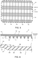
FIG. 2 ] is a view showing the soundproof heat-dissipating cover ofEmbodiment 1, where (a) is a top view, (b) is a front view, and (c) is a right side view. - [
FIG. 3 ] is a view showing a sound-absorbing heat-dissipating sheet ofEmbodiment 1, where (a) is a top view, and (b) is a front view. - [
FIG. 4 ] is a view showing a reinforcing member of Embodiment 1, where (a) is a top view, and (b) is a front view. - [
FIG. 5 ] is a partially enlarged front view showing a region R inFIG. 2 . - [
FIG. 6 ] is a partially enlarged cross-sectional view showing a state before the reinforcing member is mounted to the sound-absorbing heat-dissipating sheet inEmbodiment 1. - [
FIG. 7 ] is a partially enlarged cross-sectional view showing a state in which the reinforcing member is mounted to the sound-absorbing heat-dissipating sheet inEmbodiment 1. - [
FIG. 8 ] is a partially enlarged cross-sectional view showing a state in which the soundproof heat-dissipating cover ofEmbodiment 1 is mounted to the target object. - [
FIG. 9 ] is a partially enlarged cross-sectional view showing a state before a reinforcing member is mounted to a sound-absorbing heat-dissipating sheet inEmbodiment 2. - [
FIG. 10 ] is partially enlarged cross-sectional view showing a state in which the reinforcing member is mounted to the sound-absorbing heat-dissipating sheet inEmbodiment 2. - [
FIG. 11 ] is a partially enlarged cross-sectional view showing a state before a reinforcing member is mounted to a sound-absorbing heat-dissipating sheet inEmbodiment 3. - [
FIG. 12 ] is a partially enlarged cross-sectional view showing a state in which the soundproof heat-dissipating cover ofEmbodiment 3 is mounted to the target object. - [
FIG. 13 ] is a partially enlarged cross-sectional view showing a state in which a reinforcing member is mounted to a sound-absorbing heat-dissipating sheet inEmbodiment 4. - [
FIG. 14 ] is a partially enlarged front view showing a soundproof heat-dissipating cover ofEmbodiment 5 and showing a region corresponding to the region R inFIG. 2 . - [
FIG. 15 ] is a partially enlarged front view showing a soundproof heat-dissipating cover of Embodiment 6 and showing a region corresponding to the region R inFIG. 2 . - [
FIG. 16 ] is a partially enlarged front view showing a soundproof heat-dissipating cover of a modification example of Embodiment 6 and showing a region corresponding to the region R inFIG. 2 . - A basic configuration of a soundproof heat-dissipating
cover 1 will be described with reference toFIG. 1 ,FIG. 3 , andFIG. 4 . The soundproof heat-dissipating cover 1 has a function of covering atarget object 2 to suppress transmission of sound generated by thetarget object 2 to outside, and a function of dissipating heat of thetarget object 2 to outside. Thetarget object 2 is, for example, a power source of a vehicle. The power source may be a drive motor of a vehicle, a drive engine of a vehicle, etc. - Herein,
FIG. 1 shows a case where thetarget object 2 is a drive motor of a vehicle. Further, the drive motor inFIG. 1 is exemplified as having a cylindrical outer circumferential surface. However, the outer circumferential surface of the drive motor is not limited to a cylindrical surface, and may also be formed with protrusions and recesses as appropriate. - In this embodiment, the drive motor is disposed such that a rotational axis of the drive motor is in line with a left-right direction of the vehicle. A left side of
FIG. 1 represents a vehicle front side, and a right side ofFIG. 1 represents a vehicle rear side. A vehicle front surface of the drive motor is a region capable of directly receiving an airflow due to vehicle traveling. Further, both upper and lower lateral surfaces of the drive motor are also capable of receiving an airflow flowing from the front side to the rear side due to vehicle traveling. A vehicle rear surface of the drive motor is a region that does not directly receive an airflow during vehicle traveling. - On the other hand, in a stopped state of the vehicle, air circulates in an up-down direction due to natural convection. Thus, a lower surface of the drive motor is a surface capable of directly receiving an airflow due to natural convection. Further, both front and rear lateral surfaces of the drive motor are also capable of receiving an airflow circulating from the lower side to the upper side due to natural convection. An upper surface of the drive motor is a region that does not directly receive an airflow due to natural convection.
- As described above, in both states of vehicle traveling and vehicle stoppage, at least one of the lateral surfaces in a circumferential direction of the drive motor is a surface capable of receiving an airflow.
- However, the drive motor may also be configured to be disposed such that the rotational axis of the drive motor is in line with a front-rear direction of the vehicle. In that case, since air flows along an axial direction of the drive motor, both upper and lower lateral surfaces and both left and right lateral surfaces of the drive motor are regions capable of directly receiving an airflow due to vehicle traveling.
- The soundproof heat-dissipating
cover 1 covers the surface of thetarget object 2. For example, as shown inFIG. 1 , in the case where thetarget object 2 is a drive motor, the soundproof heat-dissipatingcover 1 covers an outer circumferential surface of the drive motor. The soundproof heat-dissipatingcover 1 covers an entire circumference of the outer circumferential surface of thetarget object 2, but a portion that is not covered may also be provided. In this embodiment, four soundproof heat-dissipatingcovers 1 cover the outer circumferential surface of thetarget object 2. In this embodiment, the four soundproof heat-dissipatingcovers 1 cover an upper surface, a lower surface, a front surface, and a rear surface of thetarget object 2. However, the number of soundproof heat-dissipatingcovers 1 may also be 1 to 3, or 5 or more. - The soundproof heat-dissipating
cover 1 includes a sound-absorbing heat-dissipatingsheet 3 and a reinforcingmember 4. The sound-absorbing heat-dissipatingsheet 3 is formed of a first sound-absorbing material having sound-absorbing properties into a surface shape, and covers the surface of thetarget object 2. Thus, a soundproofing effect can be obtained by the sound-absorbing heat-dissipatingsheet 3. The sound-absorbing heat-dissipatingsheet 3 may also be formed into a shape corresponding to the surface shape of thetarget object 2 in advance. Further, the sound-absorbing heat-dissipatingsheet 3 may also be formed of a deformable material into a planar shape, and mounted to the surface of thetarget object 2 while being deformed. The sound-absorbing heat-dissipatingsheet 3 has heat-dissipating properties in addition to sound-absorbing properties. The sound-absorbing heat-dissipatingsheet 3 includes a coveringsurface 10 that covers the surface of thetarget object 2, and a heat-dissipatingsurface 11 on the opposite side of the coveringsurface 10. - A first sound-absorbing material constituting the sound-absorbing heat-dissipating
sheet 3 is preferably formed of a material with excellent sound-absorbing properties such as a foamed resin. Examples of the foamed resin applicable may include a urethane foam, an acrylic foam, a silicone foam, a styrene foam, foamed olefin (foamed PP, foamed PE), foamed PVC, foamed EVA, foamed PA, etc. An Asker C hardness of the foamed resin of the sound-absorbing heat-dissipatingsheet 3 is 1 to 60 degrees. The sound-absorbing heat-dissipatingsheet 3 may also be formed of a non-foamed resin having sound-absorbing properties, or may also be formed of a metal. Examples of the non-foamed resin applicable may include a polyamide resin, an olefin resin, a styrene resin, a urethane resin, a silicone resin, an acrylic resin, a polyvinyl chloride resin, a polyethylene resin, a polyethylene terephthalate resin, a polycarbonate resin, a polypropylene resin, an ABS resin, an EVA resin, a carbon fiber plastic (FRP, CFRP), etc. Further, examples of the metal applicable may include iron, aluminum, stainless steel, copper, and alloys thereof. However, a foamed resin with excellent sound-absorbing properties is preferable. - Furthermore, to provide the sound-absorbing heat-dissipating
sheet 3 with heat-dissipating properties, the sound-absorbing heat-dissipatingsheet 3 may be formed of a foamed resin containing a heat-conductive material. The heat-conductive material may be extended from the coveringsurface 10 of the sound-absorbing heat-dissipatingsheet 3 toward the heat-dissipatingsurface 11. For example, in the case where the heat-conductive material is a heat-conductive filler, the heat-conductive filler is arranged from the coveringsurface 10 of the sound-absorbing heat-dissipatingsheet 3 toward the heat-dissipatingsurface 11. Furthermore, a filling amount of the heat-conductive material may vary depending on the position of the sound-absorbing heat-dissipatingsheet 3. For example, since the vehicle rear surface is more difficult to cool than the vehicle front surface, the filling amount of the heat-conductive material on the vehicle rear surface may be increased compared to the vehicle front surface. Herein, the filling amount refers to a filling amount per unit area in a plane direction of the sound-absorbing heat-dissipatingsheet 3. Further, in the case where the heat-conductive material is a metal plate, the heat-conductive material may be insert-molded to extend from the coveringsurface 10 of the sound-absorbing heat-dissipatingsheet 3 toward the heat-dissipatingsurface 11. - In a state of covering the sound-absorbing heat-dissipating
sheet 3 from the heat-dissipatingsurface 11 side, the reinforcingmember 4 positions the sound-absorbing heat-dissipatingsheet 3 with respect to thetarget object 2. The reinforcingmember 4 is formed separately from the sound-absorbing heat-dissipatingsheet 3, and is disposed on the heat-dissipatingsurface 11 side of the sound-absorbing heat-dissipatingsheet 3 such that the sound-absorbing heat-dissipatingsheet 3 is interposed between the reinforcingmember 4 and thetarget object 2. - Further, as a method for fixing to the
target object 2, for example, as shown inFIG. 1 , the reinforcingmember 4 may be fixed to thetarget object 2 bybolts 5. The sound-absorbing heat-dissipatingsheet 3 has first insertion holes 12 that are formed to penetrate the sound-absorbing heat-dissipatingsheet 3 and into which thebolts 5 are inserted (seeFIG. 3 ). The reinforcingmember 4 has second insertion holes 20 that are formed to penetrate the reinforcingmember 4 and into which thebolts 5 are inserted (seeFIG. 4 ). However, the method of fixing the reinforcingmember 4 and thetarget object 2 is not limited to bolt fastening, and for example, the reinforcingmember 4 may also be configured to engage with engaging claws provided at thetarget object 2. In the case where the reinforcingmember 4 and thetarget object 2 are not fastened by bolts, the first insertion holes 12 and the second insertion holes 20 are omitted. - The reinforcing
member 4 is formed of a material with a hardness higher than the sound-absorbing heat-dissipatingsheet 3. In this embodiment, the sound-absorbing heat-dissipatingsheet 3 is formed of, for example, a foamed resin into a surface shape. An Asker C hardness of the foamed resin of the reinforcingmember 4 is 60 to 99 degrees. Thus, in the case where the sound-absorbing heat-dissipatingsheet 3 is formed of a first sound-absorbing material that does not have a sufficient rigidity, a positioning effect with respect to thetarget object 2 by the sound-absorbing heat-dissipatingsheet 3 alone is low. Even in such a case, with the reinforcingmember 4, the sound-absorbing heat-dissipatingsheet 3 can be reliably positioned with respect to thetarget object 2. - Furthermore, the reinforcing
member 4 is formed of a material with a mass per unit volume (hereinafter referred to as a "unit mass") greater than the sound-absorbing heat-dissipatingsheet 3. As described above, to enable the reinforcingmember 4 to exhibit a reinforcing function, the reinforcingmember 4 is consequently formed of a material with a unit mass greater than the sound-absorbing heat-dissipatingsheet 3. - The reinforcing
member 4 may also be configured to be formed of a second sound-absorbing material having sound-absorbing properties. The second sound-absorbing material may be formed of a material with excellent sound-absorbing properties such as a foamed resin. However, the foamed resin applicable to the reinforcingmember 4 is different from the foamed resin applicable to the sound-absorbing heat-dissipatingsheet 3. For example, examples of the foamed resin applicable to the reinforcingmember 4 may include a urethane foam, an acrylic foam, a silicone foam, a styrene foam, foamed olefin (foamed PP, foamed PE), foamed PVC, foamed EVA, foamed PA, etc. Even if the urethane foam is applied to the sound-absorbing heat-dissipatingsheet 3 and the reinforcingmember 4, the urethane foams of the two are of different types. By forming the reinforcingmember 4 with the second sound-absorbing material, the soundproofing properties of the soundproof heat-dissipatingcover 1 can be improved. - Further, the reinforcing
member 4 may also include a material different from the second sound-absorbing material, such as a foamed rubber, a non-foamed resin, or a metal. Examples of the foamed rubber applicable may include foamed EPDM, foamed CR, foamed NBR/PVC, foamed ACM, etc. Further, examples of the non-foamed resin applicable may include a polyamide resin, an olefin resin, a styrene resin, a urethane resin, a silicone resin, an acrylic resin, a polyvinyl chloride resin, a polyethylene resin, a polyethylene terephthalate resin, a polycarbonate resin, a polypropylene resin, an ABS resin, an EVA resin, a carbon fiber plastic (FRP, CFRP), etc. Further, examples of the metal applicable may include iron, aluminum, stainless steel, copper, and alloys thereof. In these cases, the reinforcing member is formed of a rubber, a resin, or a metal with a hardness higher than a foamed resin. However, from the perspective of weight reduction, a foamed resin is preferable. - Further, the reinforcing
member 4 is not disposed to cover the entire surface of the sound-absorbing heat-dissipatingsheet 3, and is disposed in a state of exposing at least a part of the sound-absorbing heat-dissipatingsheet 3. As described above, the sound-absorbing heat-dissipatingsheet 3 has heat-dissipating properties in addition to sound-absorbing properties. Thus, by exposing the sound-absorbing heat-dissipatingsheet 3, a heat dissipation performance due to the sound-absorbing heat-dissipatingsheet 3 can be effectively exhibited. - In the case where the reinforcing
member 4 has a flexibility allowing deflection deformation, the reinforcingmember 4 may be mounted to the outer circumferential surface of thetarget object 2 while being deformed to conform to the shape of the outer circumferential surface of thetarget object 2. Further, in the case where the reinforcingmember 4 has a high hardness and is thus difficult to deflect and deform, the reinforcingmember 4 may be formed in advance to conform to the shape of the outer circumferential surface of thetarget object 2. Accordingly, the reinforcingmember 4 can be easily mounted to the outer circumferential surface of thetarget object 2. - A detailed configuration of the soundproof heat-dissipating
cover 1 will be described with reference toFIG. 1 to FIG. 8 . As shown inFIG. 1 , the soundproof heat-dissipatingcover 1 is formed into a shape corresponding to the surface shape of thetarget object 2. However, to facilitate description,FIG. 2 to FIG. 8 show the soundproof heat-dissipatingcover 1 in a state expanded into a planar shape, and the following description will refer to these figures. - As shown in (a) of
FIG. 2 and (c) ofFIG. 2 , the soundproof heat-dissipatingcover 1 includes a sound-absorbing heat-dissipatingsheet 3 and a reinforcingmember 4. The sound-absorbing heat-dissipatingsheet 3 and the reinforcingmember 4 will be described in detail below. In this example, the sound-absorbing heat-dissipatingsheet 3 is composed of one sheet only. However, the sound-absorbing heat-dissipatingsheet 3 may also be composed of a plurality of divide bodies formed separately. The soundproof heat-dissipatingcover 1 is formed into a substantially rectangular shape in a plan view. However, the shape of the soundproof heat-dissipatingcover 1 is not particularly limited and may be formed into any shape. - As shown in (a) of
FIG. 3 and (b) ofFIG. 3 , although not particularly limited, in this embodiment, the sound-absorbing heat-dissipatingsheet 3 is formed into a substantially rectangular shape in a plan view. The sound-absorbing heat-dissipatingsheet 3 is formed into a surface shape as a whole. In a state of being mounted to thetarget object 2, the sound-absorbing heat-dissipatingsheet 3 includes a pair of first mountingparts 13 formed at positions near both ends in the axial direction (an example of a first direction) of thetarget object 2, and a heat-dissipatingregion 14 formed between the pair of first mountingparts 13. First insertion holes 12 penetrating the sound-absorbing heat-dissipatingsheet 3 are formed at four corner parts of the sound-absorbing heat-dissipatingsheet 3 at which the pair of first mountingparts 13 are formed. As described above, the first insertion holes 12 are configured forbolts 5 to insert therein. The coveringsurface 10 of the sound-absorbing heat-dissipatingsheet 3 covers and contacts a part of the surface of thetarget object 2. - A plurality of
ridges 15 are formed protruding outward on the heat-dissipatingsurface 11 of the heat-dissipatingregion 14. The plurality ofridges 15 are formed to extend in a plane direction of the sound-absorbing heat-dissipatingsheet 3. Specifically, with the sound-absorbing heat-dissipatingsheet 3 mounted to thetarget object 2, the plurality ofridges 15 are formed extending in a straight line shape along the circumferential direction of the outer circumferential surface of thetarget object 2. The plurality ofridges 15 are arranged side by side at an interval in the axial direction of thetarget object 2 on the heat-dissipatingsurface 11 of the heat-dissipatingregion 14. In this embodiment, the plurality ofridges 15 are formed to be arranged side by side at an equal interval. However, the shape of the plurality ofridges 15 may also be a wave shape in a plan view. Further, the plurality ofridges 15 may also be formed to extend in the axial direction of the outer circumferential surface of thetarget object 2, or may also be formed into a shape that extends in a direction inclined with respect to the circumferential direction and the axial direction of the outer circumferential surface of thetarget object 2. - In the case where the sound-absorbing heat-dissipating
sheet 3 is formed of, for example, a foamed resin containing a heat-conductive material, the heat-conductive material may be extended continuously in a surface normal direction of the sound-absorbing heat-dissipatingsheet 3, from the coveringsurface 10 of the sound-absorbing heat-dissipatingsheet 3 to a tip of theridge 15. Accordingly, by continuously disposing the heat-conductive material in a range from the surface of thetarget object 2 to the tip of theridge 15, a high heat dissipation performance can be exhibited. The heat-conductive material of this case is preferably an electrically conductive filler. - In the case where the sound-absorbing heat-dissipating
sheet 3 is formed of, for example, a foamed resin containing a heat-conductive material, the heat-conductive material may be extended continuously in an extending direction of theridge 15 on a tip side of theridge 15. Accordingly, by continuously disposing the heat-conductive material in a range from one end side to the other end side in the extending direction of theridge 15, a high heat dissipation performance can also be exhibited in the plane direction. Examples of the heat-conductive material applicable in this case may include a metal foil such as copper, stainless steel, steel, or aluminum, a metal film such as an aluminum-deposited film, an electrically conductive filler, a heat-conductive resin film, etc. Further, a metal foil or a metal film and a resin film may also be laminated. The heat-conductive material may also be provided only in specific regions of the plurality ofridges 15 or provided atspecific ridges 15 only, and may also be disposed on an outer surface on a tip side or a lateral surface of theridge 15. - Further, in the case where the sound-absorbing heat-dissipating
sheet 3 is formed of a foamed resin, the sound-absorbing heat-dissipatingsheet 3 may be configured as follows. The heat-dissipatingsurface 11 side of the sound-absorbing heat-dissipatingsheet 3 may be in a closed-cell state in which cells of the foamed resin are closed, and the coveringsurface 10 side may be in an open-cell state in which the cells of the foamed resin are open. By configuring the heat-dissipatingsurface 11 side in the closed-cell state, a pressure loss during circulation of a fluid such as air can be suppressed, so the heat dissipation performance can be enhanced. On the other hand, by configuring the coveringsurface 10 side in the open-cell state, a sound absorption performance can be enhanced. In other words, with the above configuration, the sound absorption performance and the heat dissipation performance can be improved. - As shown in (a) of
FIG. 4 and (b) ofFIG. 4 , in this embodiment, the reinforcingmember 4 is composed of one component only. However, the reinforcingmember 4 may also be composed of a plurality of divided bodies. - The reinforcing
member 4 is formed into a substantially rectangular shape in a plan view. The reinforcingmember 4 is formed in an approximately same size as the sound-absorbing heat-dissipatingsheet 3 in a plan view. In a state of being mounted to thetarget object 2, the reinforcingmember 4 includes a pair of second mountingparts 21 formed at positions near both ends in the axial direction of thetarget object 2, and a bridgingpart 22 that bridges between the pair of second mountingparts 21. - The pair of second mounting
parts 21 are configured to be respectively mounted to the pair of first mountingparts 13 of the sound-absorbing heat-dissipatingsheet 3. The pair of second mountingparts 21 have mountingsurfaces 24 that are opposed to the pair of first mountingparts 13 and are mounted to the pair of first mountingparts 13 by a conventional means such as an adhesive or a double-sided tape 23. In this embodiment, the second mountingpart 21 is mounted to the first mountingpart 13 by a double-sided tape 23. In the axial direction of thetarget object 2, a width dimension of the pair of second mountingparts 21 is smaller than a width dimension of the pair of first mountingparts 13. Second insertion holes 20 penetrating the second mountingparts 21 are formed at the pair of second mountingparts 21. As described above, the second insertion holes 20 are configured for thebolts 5 to insert therein. - The bridging
part 22 includes anaccommodating recess 25 formed into a recess shape in a direction away from the sound-absorbing heat-dissipating sheet, on a surface on a side opposed to the sound-absorbing heat-dissipatingsheet 3. With the second mountingparts 21 of the reinforcing member mounted to the first mountingparts 13 of the sound-absorbing heat-dissipatingsheet 3, theaccommodating recess 25 of the reinforcing member is configured to accommodate the heat-dissipatingregion 14 of the sound-absorbing heat-dissipatingsheet 3. The second mountingpart 21 and abottom wall 26 of theaccommodating recess 25 are connected by aninclined wall 27 that expands to the second mountingpart 21 side. Thebottom wall 26 of theaccommodating recess 25 has aninner surface 28 opposed to the sound-absorbing heat-dissipatingsheet 3, and anouter surface 29 on the opposite side of theinner surface 28. - As shown in (a) of
FIG. 2 , with the reinforcingmember 4 mounted to the sound-absorbing heat-dissipatingsheet 3, ventilation holes 30 are formed on both lateral surfaces of the bridgingpart 22 that intersect with the circumferential direction of thetarget object 2 to allow air to circulate with respect to the heat-dissipatingregion 14 of the sound-absorbing heat-dissipatingsheet 3. As described above, since air is capable of circulating along the circumferential direction of thetarget object 2, air is capable of flowing into the reinforcingmember 4 from the ventilation holes 30 and flowing out to outside. The plurality ofridges 15 of the sound-absorbing heat-dissipatingsheet 3 are exposed at the ventilation holes 30. Accordingly, the air flowing into the reinforcingmember 4 from the ventilation holes 30 and flowing out to outside is capable of contacting the plurality ofridges 15. As a result, the heat dissipation performance of the soundproof heat-dissipatingcover 1 is improved. Furthermore, as described above, since the plurality ofridges 15 are formed to extend in a straight line shape, circulation of air is not obstructed. Accordingly, the heat dissipation performance of the soundproof heat-dissipatingcover 1 can be improved. However, as described above, in the case where air flows along the axial direction of the drive motor, by configuring the plurality ofridges 15 to extend along the axial direction, obstruction to circulation of air can be suppressed. - As shown in (b) of
FIG. 2 and(b) ofFIG. 4 , the bridgingpart 22 includes a plurality of through-holes 31 that penetrate the bridgingpart 22. In this embodiment, the plurality of through-holes 31 are formed into an elongated slit shape extending in a direction in which the plurality ofridges 15 of the sound-absorbing heat-dissipatingsheet 3 are arranged side by side. The plurality of through-holes 31 are formed to be arranged side by side at an interval in the extending direction of the plurality ofridges 15. In this embodiment, the direction in which the plurality of through-holes 31 extend is orthogonal to the direction in which the plurality ofridges 15 extend. However, the direction in which the plurality of through-holes 31 extend and the direction in which the plurality ofridges 15 extend may also be configured to be inclined and intersect with each other. - In relation to the
target object 2, the shape of the plurality of through-holes 31 is described as follows: the plurality of through-holes 31 are formed into an elongated slit shape extending in the axial direction of thetarget object 2, and are formed to be arranged side by side at an interval along the circumferential direction of theouter surface 29 of thetarget object 2. - In this embodiment, the plurality of through-
holes 31 are of the same shape and the same size. Further, the plurality of through-holes 31 are arranged side by side at an equal interval. However, the shape and the size of the plurality of through-holes 31 may also differ from each another, and the intervals between the plurality of through-holes 31 may also differ from each other. - As shown in (b) of
FIG. 2 andFIG. 5 , with the reinforcingmember 4 mounted to the sound-absorbing heat-dissipatingsheet 3, at least oneridge 15 is exposed to outside from at least one through-hole 31. Accordingly, since heat generated from thetarget object 2 can be dissipated to outside through the through-holes 31 from theridges 15 of the sound-absorbing heat-dissipatingsheet 3, the heat dissipation performance of the soundproof heat-dissipatingcover 1 can be improved. In the illustration inFIG. 5 , the color tone of the bridgingpart 22 is changed to make it easier to distinguish between the bridgingpart 22 and the through-holes 31. - As shown in
FIG. 6 , in this embodiment, in a state before the reinforcingmember 4 is mounted to the sound-absorbing heat-dissipatingsheet 3, a protrusion height dimension T1 of theridge 15 protruding on the heat-dissipatingsurface 11 of the sound-absorbing heat-dissipatingsheet 3 is set to be larger than a height dimension T2 between the mountingsurface 24 of the second mountingpart 21 and theinner surface 28 of the bridgingpart 22 of the reinforcingmember 4. However, the protrusion height dimension T1 of theridge 15 protruding on the heat-dissipatingsurface 11 of the sound-absorbing heat-dissipatingsheet 3 may also be set to be equal to the height dimension T2 between the mountingsurface 24 of the second mountingpart 21 and theinner surface 28 of the bridgingpart 22 of the reinforcingmember 4. - Although the state in which the sound-absorbing heat-dissipating
sheet 3 is supported from below by the reinforcingmember 4 has been described in this embodiment, the relative positional relationship between the sound-absorbing heat-dissipatingsheet 3 and the reinforcingmember 4 is not particularly limited. - As shown in
FIG. 7 , with the reinforcingmember 4 mounted to the sound-absorbing heat-dissipatingsheet 3, a tip of theridge 15 of the sound-absorbing heat-dissipatingsheet 3 abuts against theinner surface 28 of the bridgingpart 22 of the reinforcingmember 4. Furthermore, as described above, in this embodiment, the protrusion height dimension T1 of theridge 15 in the state before the reinforcingmember 4 is mounted to the sound-absorbing heat-dissipatingsheet 3 is set to be larger than the height dimension T2 between the mountingsurface 24 of the second mountingpart 21 and theinner surface 28 of the bridgingpart 22 of the reinforcingmember 4. Thus, with the reinforcingmember 4 mounted to the sound-absorbing heat-dissipatingsheet 3, theridge 15 becomes compressed in the protruding direction of theridge 15 by the bridgingpart 22 of the reinforcing member. - With the plurality of
ridges 15 of the sound-absorbing heat-dissipatingsheet 3 abutting against the bridgingpart 22 of the reinforcingmember 4, the plurality ofridges 15 of the sound-absorbing heat-dissipatingsheet 3 are supported by the bridgingpart 22 of the reinforcingmember 4. Accordingly, deformation of the sound-absorbing heat-dissipatingsheet 3 into a protruding shape in a direction from the coveringsurface 10 toward the heat-dissipatingsurface 11 is suppressed. As a result, since deflection deformation of the coveringsurface 10 of the sound-absorbing heat-dissipatingsheet 3 away from thetarget object 2 is suppressed, formation of a gap between thetarget object 2 and the coveringsurface 10 of the sound-absorbing heat-dissipatingsheet 3 is suppressed. Accordingly, since heat generated from thetarget object 2 is quickly conducted to the sound-absorbing heat-dissipatingsheet 3, the heat dissipation performance of the soundproof heat-dissipatingcover 1 is improved. - Further, with the plurality of
ridges 15 receiving pressure from the reinforcingmember 4 and compressed, the sound-absorbing heat-dissipatingsheet 3 is pressed against thetarget object 2. Accordingly, adhesion between the sound-absorbing heat-dissipatingsheet 3 and thetarget object 2 is improved. As a result, the heat dissipation performance of the soundproof heat-dissipatingcover 1 is further improved. - As shown in
FIG. 7 , with theridge 15 compressed by the bridgingpart 22 of the reinforcingmember 4, at least a part of the coveringsurface 10 of the sound-absorbing heat-dissipatingsheet 3 includes a bulgingpart 16 that bulges to the side opposite to the reinforcingmember 4. In this embodiment, theentire covering surface 10 in the heat-dissipatingregion 14 of the sound-absorbing heat-dissipatingsheet 3 forms the bulgingpart 16. In this embodiment, the bulgingpart 16 includes the heat-conductive material described above. However, it is also possible that a part of the coveringsurface 10 of the sound-absorbing heat-dissipatingsheet 3 bulges, and it is also possible that the coveringsurface 10 of the sound-absorbing heat-dissipatingsheet 3 does not include a bulgingpart 16. - As shown in
FIG. 8 , with the soundproof heat-dissipatingcover 1 mounted to thetarget object 2, the coveringsurface 10 of the sound-absorbing heat-dissipatingsheet 3 covers the surface of the target object. The bulgingpart 16 bulging on the coveringsurface 10 of the sound-absorbing heat-dissipatingsheet 3 reliably contacts thetarget object 2 and is compressed by thetarget object 2. Accordingly, since adhesion between the sound-absorbing heat-dissipatingsheet 3 and thetarget object 2 is improved, the heat dissipation performance of the soundproof heat-dissipatingcover 1 is improved. Although the state in which the soundproof heat-dissipatingcover 1 is mounted to the lower surface of thetarget object 2 has been described in this embodiment, the portion of thetarget object 2 to which the soundproof heat-dissipatingcover 1 is mounted is not particularly limited. - Further, with the bulging
part 16 being defined on theentire covering surface 10 in the heat-dissipatingregion 14, since adhesion between the sound-absorbing heat-dissipatingsheet 3 and thetarget object 2 is improved over theentire covering surface 10 in the heat-dissipatingregion 14, the heat dissipation performance of the soundproof heat-dissipatingcover 1 is improved. - Further, by including the heat-conductive material in the bulging
part 16, since it becomes possible to quickly transfer heat emitted by thetarget object 2 to the sound-absorbing heat-dissipatingsheet 3, the heat dissipation performance of the soundproof heat-dissipatingcover 1 is improved. - Next, referring to
FIG. 9 and FIG. 10 , a soundproof heat-dissipatingcover 41 ofEmbodiment 2 will be described. As shown inFIG. 9 , a reinforcingmember 42 of the soundproof heat-dissipatingcover 41 in this embodiment hasfitting recesses 43 on theinner surface 28 of the bridgingpart 22. With the reinforcingmember 42 mounted to the sound-absorbing heat-dissipatingsheet 3, thefitting recesses 43 are formed as depressed at positions opposed to the tips of the plurality ofridges 15 of the sound-absorbing heat-dissipatingsheet 3. Similar to the plurality ofridges 15, thefitting recesses 43 are formed extending along the circumferential direction of thetarget object 2. An opening of thefitting recess 43 is formed in a size allowing the tip of theridge 15 to fit therein. - As shown in
FIG. 10 , with the reinforcingmember 42 mounted to the sound-absorbing heat-dissipatingsheet 3, the tip of theridge 15 is configured to fit into thefitting recess 43. Accordingly, deflection deformation of theridge 15 due to gravity or heat of thetarget object 2 is suppressed. As a result, since formation of a gap between theridge 15 of the sound-absorbing heat-dissipatingsheet 3 and the bridgingpart 22 of the reinforcingmember 42 is suppressed, the heat dissipation performance of the soundproof heat-dissipatingcover 41 can be improved. - Among the reference signs used in
Embodiment 2 and subsequent embodiments, reference signs identical to the reference signs used in previous embodiments represent similar components as in the previous embodiments unless otherwise specified. - Next, referring to
FIG. 11 and FIG. 12 , a soundproof heat-dissipatingcover 51 ofEmbodiment 3 will be described. As shown inFIG. 11 , a first mountingpart 53 provided at a sound-absorbing heat-dissipatingsheet 52 in this embodiment is formed protruding in the protruding direction of theridge 15. A protrusion height dimension T3 of the first mountingpart 53 is set to be larger than the protrusion height dimension T1 of theridge 15. Accordingly, a step is formed between the first mountingpart 53 and the heat-dissipatingregion 14 in the protruding direction of theridge 15. - A reinforcing
member 54 in this embodiment is formed into a flat plate shape. A step is not formed between a pair of second mountingparts 55 and a portion other than the pair of second mountingparts 55 on theinner surface 28 of the reinforcingmember 54. - As shown in
FIG. 12 , with the second mountingpart 55 of the reinforcingmember 54 mounted to the first mountingpart 53 of the sound-absorbing heat-dissipatingsheet 52, a space is formed by the protrusion height dimension T3 of the first mountingpart 53 between the heat-dissipatingregion 14 of the sound-absorbing heat-dissipatingsheet 52 and the bridgingpart 56 of the reinforcingmember 54. This space is configured to accommodate the heat-dissipatingregion 14 and the plurality ofridges 15 of the sound-absorbing heat-dissipatingsheet 52. The protrusion height dimension T3 of the first mountingpart 53 may also be set to be smaller than the protrusion height dimension T1 of theridge 15. In that case, the plurality ofridges 15 are accommodated in the space in a compressed state. - Next, referring to
FIG. 13 , a soundproof heat-dissipatingcover 61 ofEmbodiment 4 will be described. In this embodiment, with a second mountingpart 21 of a reinforcingmember 62 mounted to the first mountingpart 13 of the sound-absorbing heat-dissipatingsheet 3, a compressingprotrusion 63 protruding toward the sound-absorbing heat-dissipatingsheet 3 is formed on aninner surface 28 of a bridgingpart 22 of a reinforcingmember 62 of the soundproof heat-dissipatingcover 61. - The compressing
protrusion 63 may be formed at at least a part of theinner surface 28 of the bridgingpart 22. However, the entireinner surface 28 of the bridgingpart 22 may also serve as the compressingprotrusion 63 with the entireinner surface 28 of the bridgingpart 22 protruding toward the sound-absorbing heat-dissipatingsheet 3. Since the plurality ofridges 15 of the sound-absorbing heat-dissipatingsheet 3 are compressed by the compressingprotrusion 63, the heat dissipation performance of the soundproof heat-dissipatingcover 61 is further improved. - As described above, with the plurality of
ridges 15 compressed by the bridgingpart 22, a bulgingpart 16 is formed on the coveringsurface 10 of the sound-absorbing heat-dissipatingsheet 3. Furthermore, with theridges 15 compressed by the compressingprotrusion 63, an additional bulgingpart 64 protruding further from the bulgingpart 16 is formed on the coveringsurface 10 of the sound-absorbing heat-dissipatingsheet 3. The additional bulgingpart 64 is formed at a position that overlaps with the compressingprotrusion 63 of the bridgingpart 22 in the protruding direction of theridge 15. - With the soundproof heat-dissipating
cover 61 mounted to thetarget object 2, the portion at which the additional bulgingpart 64 is formed is more strongly compressed by thetarget object 2. Accordingly, since formation of a gap between the sound-absorbing heat-dissipatingsheet 3 and the target object is suppressed, the heat dissipation performance of the soundproof heat-dissipatingcover 61 is further improved. This is particularly effective in the case where local high-temperature portions are present on thetarget object 2. - Next, referring to
FIG. 14 , a soundproof heat-dissipatingcover 71 ofEmbodiment 5 will be described. As shown inFIG. 14 , in this embodiment, a plurality of through-holes 72 with a circular inner shape are formed at the bridgingpart 22. The plurality of through-holes 72 are arranged side by side at an interval along the direction in which the plurality ofridges 15 extend, and are arranged side by side at an interval along the direction in which the plurality ofridges 15 are arranged. A part of theridge 15 is exposed from each through-hole 72. Accordingly, heat generated by thetarget object 2 is transferred to the sound-absorbing heat-dissipatingsheet 3, is then conducted to theridge 15, and is dissipated to outside through the through-hole 72 from theridge 15. Accordingly, the heat dissipation performance of the soundproof heat-dissipatingcover 71 can be improved. - Further, a portion of the bridging
part 22 at which the through-holes 72 are not formed abuts against the tips of the plurality ofridges 15. Accordingly, deformation of the sound-absorbing heat-dissipatingsheet 3 away from the surface of thetarget object 2 is suppressed. As a result, since formation of a gap between the sound-absorbing heat-dissipatingsheet 3 and thetarget object 2 is suppressed, the heat dissipation performance of the soundproof heat-dissipatingcover 71 can be improved. - However, the plurality of through-
holes 72 may also be configured to be disposed along only one of the extending direction of theridge 15 and the arrangement direction of theridges 15, and not along the other direction. Further, the plurality of through-holes 72 may also be disposed randomly, without being arranged along either of the extending direction of theridge 15 and the arrangement direction of theridges 15. - Next, referring to
FIG. 15 , a soundproof heat-dissipatingcover 81 of Embodiment 6 will be described. In this embodiment, a plurality of through-holes 72 with a circular inner shape are disposed in a staggered pattern at the bridgingpart 22. - A portion of the bridging
part 22 at which the plurality of through-holes 72 disposed in a staggered pattern are not formed defines a shape in which elongated strip-shaped portions intersect obliquely with both of the extending direction of the plurality ofridges 15 and the arrangement direction of the plurality ofridges 15. Accordingly, since the plurality ofridges 15 can be evenly supported without bias, deformation of the sound-absorbing heat-dissipatingsheet 3 in a direction away from thetarget object 2 can be further suppressed. As a result, the heat dissipation performance of the soundproof heat-dissipatingcover 81 can be improved. -
FIG. 16 illustrates a modification example of Embodiment 6. In this embodiment, an inner shape of a plurality of through-holes 82a is formed into a hexagon. The inner shape of the plurality of through-holes 82a is not limited to a circle or a hexagon, and may also be a polygon such as a triangle, a square, a pentagon, etc., or may also be an elliptical shape, and any shape may be selected as appropriate. - Furthermore, the shape of the plurality of through-
holes 82a may be configured such that sizes of the plurality of through-holes 82a are different from each other. For example, in the case where portions prone to becoming locally high-temperature are present on thetarget object 2, by configuring the size of the through-holes 82a corresponding to the portions prone to becoming high-temperature to be larger than other portions, the heat dissipation performance of the soundproof heat-dissipatingcover 81 can be improved. - The present disclosure is not limited to the above-described embodiments, and is applicable to various embodiments within a scope without deviating from the spirit thereof.
Claims (18)
- A soundproof heat-dissipating cover (1, 41, 61, 71, 81) covering a target object (2), the soundproof heat-dissipating cover comprising:a sound-absorbing heat-dissipating sheet (3) that is formed of a first sound-absorbing material into a surface shape, and comprises a covering surface (10) covering a surface of the target object and a heat-dissipating surface (11) on a side opposite to the covering surface; anda reinforcing member (4, 42, 62) that is formed of a material having a hardness higher than the first sound-absorbing material, and covers the sound-absorbing heat-dissipating sheet from a heat-dissipating surface side of the sound-absorbing heat-dissipating sheet, whereinthe sound-absorbing heat-dissipating sheet further comprises:a pair of first mounting parts (13, 53) formed at positions near both ends in a first direction along the covering surface; anda heat-dissipating region (14) formed between the pair of first mounting parts,the heat-dissipating surface in the heat-dissipating region of the sound-absorbing heat-dissipating sheet is formed with a plurality of ridges (15) arranged side by side at an interval,the reinforcing member comprises:a pair of second mounting parts (21, 55) that are formed at positions near both ends in the first direction and are respectively mounted to the pair of first mounting parts; anda bridging part (22, 56) that bridges between the pair of second mounting parts and has a plurality of through-holes (31, 72, 82a), andwith the pair of second mounting parts of the reinforcing member mounted to the pair of first mounting parts of the sound-absorbing heat-dissipating sheet, the plurality of ridges of the sound-absorbing heat-dissipating sheet abut against the bridging part of the reinforcing member.
- The soundproof heat-dissipating cover according to claim 1, wherein
the reinforcing member is formed of a second sound-absorbing material having sound-absorbing properties. - The soundproof heat-dissipating cover according to claim 1, wherein
the bridging part comprises an accommodating recess (25) that is formed on a surface on a side opposed to the sound-absorbing heat-dissipating sheet, is formed into a recess shape in a direction away from the sound-absorbing heat-dissipating sheet, and accommodates the heat-dissipating region of the sound-absorbing heat-dissipating sheet. - The soundproof heat-dissipating cover according to claim 1, wherein
with the second mounting parts of the reinforcing member mounted to the first mounting parts of the sound-absorbing heat-dissipating sheet, the plurality of ridges are compressed by the bridging part of the reinforcing member in a direction in which the plurality of ridges protrude. - The soundproof heat-dissipating cover according to claim 4, wherein
with the second mounting parts of the reinforcing member mounted to the first mounting parts of the sound-absorbing heat-dissipating sheet, at least a part of the covering surface in the heat-dissipating region comprises a bulging part (16) that bulges to a side opposite to the reinforcing member. - The soundproof heat-dissipating cover according to claim 5, wherein
the entire covering surface in the heat-dissipating region defines the bulging part. - The soundproof heat-dissipating cover according to claim 1, whereinthe bridging part comprises an accommodating recess that is formed on a surface on a side opposed to the sound-absorbing heat-dissipating sheet, is formed into a recess shape in a direction away from the sound-absorbing heat-dissipating sheet, and accommodates the heat-dissipating region of the sound-absorbing heat-dissipating sheet, andin a state before the second mounting parts of the reinforcing member are mounted to the first mounting parts of the sound-absorbing heat-dissipating sheet,at least a part of the plurality of ridges has a protrusion height dimension from the heat-dissipating surface of the sound-absorbing heat-dissipating sheet that is formed to be larger than a depth dimension of the accommodating recess depressed from the second mounting parts, andwith the second mounting parts of the reinforcing member mounted to the first mounting parts of the sound-absorbing heat-dissipating sheet, at least a part of the plurality of ridges is compressed by the bridging part of the reinforcing member in a height direction in which the plurality of ridges protrude.
- The soundproof heat-dissipating cover according to claim 1, wherein
with the second mounting parts of the reinforcing member mounted to the first mounting parts of the sound-absorbing heat-dissipating sheet, the bridging part of the reinforcing member is provided with a fitting recess (43) into which tips of at least a part of the ridges among the plurality of ridges of the sound-absorbing heat-dissipating sheet fit. - The soundproof heat-dissipating cover according to claim 1, wherein
with the second mounting parts of the reinforcing member mounted to the first mounting parts of the sound-absorbing heat-dissipating sheet, at least a part of the bridging part of the reinforcing member is formed with a compressing protrusion (63) that protrudes toward the sound-absorbing heat-dissipating sheet. - The soundproof heat-dissipating cover according to claim 1, wherein
with the second mounting parts of the reinforcing member mounted to the first mounting parts of the sound-absorbing heat-dissipating sheet, at least two or more through-holes among the plurality of through-holes are formed to be arranged side by side at an interval along a direction in which the plurality of ridges extend. - The soundproof heat-dissipating cover according to claim 10, wherein
at least two or more through-holes among the plurality of through-holes are formed into a slit shape elongated in a direction in which the plurality of ridges are arranged side by side, and are formed to be arranged side by side at an interval along a direction in which the plurality of ridges extend. - The soundproof heat-dissipating cover according to claim 11, whereinthe plurality of ridges are formed to extend in a straight line shape, andat least two or more through-holes among the plurality of through-holes are formed into a slit shape elongated in a direction orthogonal to a direction in which the plurality of ridges extend.
- The soundproof heat-dissipating cover according to claim 10, wherein
at the bridging part of the reinforcing member, at least two or more through-holes among the plurality of through-holes are formed to be arranged side by side at an interval along a direction in which the plurality of ridges are arranged side by side. - The soundproof heat-dissipating cover according to claim 10, wherein
the plurality of through-holes are disposed in a staggered pattern. - The soundproof heat-dissipating cover according to claim 1, wherein
the plurality of through-holes comprise through-holes in sizes different from each other. - The soundproof heat-dissipating cover according to claim 1, whereinat least a part of the heat-dissipating region comprises a heat-conductive material, andthe heat-conductive material extends along a surface normal direction of the sound-absorbing heat-dissipating sheet.
- The soundproof heat-dissipating cover according to claim 16, wherein
the heat-conductive material extends along a direction in which the plurality of ridges extend, on a tip side of the plurality of ridges of the sound-absorbing heat-dissipating sheet. - The soundproof heat-dissipating cover according to claim 16 or 17, whereinwith the second mounting parts of the reinforcing member mounted to the first mounting parts of the sound-absorbing heat-dissipating sheet, at least a part of the covering surface in the heat-dissipating region comprises a bulging part that bulges to a side opposite to the reinforcing member, andthe heat-conductive material is included in the bulging part.
Applications Claiming Priority (2)
| Application Number | Priority Date | Filing Date | Title |
|---|---|---|---|
| JP2022177359A JP7576600B2 (en) | 2022-11-04 | 2022-11-04 | Soundproof heat dissipation cover |
| PCT/JP2023/039596 WO2024096096A1 (en) | 2022-11-04 | 2023-11-02 | Soundproof heat-dissipating cover |
Publications (3)
| Publication Number | Publication Date |
|---|---|
| EP4550307A1 true EP4550307A1 (en) | 2025-05-07 |
| EP4550307A4 EP4550307A4 (en) | 2025-10-08 |
| EP4550307B1 EP4550307B1 (en) | 2026-03-04 |
Family
ID=90930634
Family Applications (1)
| Application Number | Title | Priority Date | Filing Date |
|---|---|---|---|
| EP23885850.0A Active EP4550307B1 (en) | 2022-11-04 | 2023-11-02 | Soundproof heat-dissipating cover |
Country Status (5)
| Country | Link |
|---|---|
| US (1) | US20250061875A1 (en) |
| EP (1) | EP4550307B1 (en) |
| JP (1) | JP7576600B2 (en) |
| CN (1) | CN119585789A (en) |
| WO (1) | WO2024096096A1 (en) |
Family Cites Families (7)
| Publication number | Priority date | Publication date | Assignee | Title |
|---|---|---|---|---|
| JPS51157742U (en) * | 1975-06-10 | 1976-12-15 | ||
| JPH1039875A (en) * | 1996-07-19 | 1998-02-13 | Mitsubishi Heavy Ind Ltd | Sound insulating material structure and soundproof structure of air conditioner |
| JP2006257993A (en) * | 2005-03-17 | 2006-09-28 | Tokai Rubber Ind Ltd | Soundproof cover |
| US7413053B2 (en) | 2006-01-25 | 2008-08-19 | Siemens Power Generation, Inc. | Acoustic resonator with impingement cooling tubes |
| JP2017146340A (en) | 2016-02-15 | 2017-08-24 | 株式会社オートネットワーク技術研究所 | Sound absorbing plate, electric wire with sound absorbing plate, method for producing sound absorbing plate |
| JP2022019421A (en) * | 2020-07-17 | 2022-01-27 | 昭和電工マテリアルズ株式会社 | Soundproof and heat radiation material and apparatus with soundproof and heat radiation material |
| JP7174747B2 (en) | 2020-12-07 | 2022-11-17 | 住友理工株式会社 | soundproof cover |
-
2022
- 2022-11-04 JP JP2022177359A patent/JP7576600B2/en active Active
-
2023
- 2023-11-02 EP EP23885850.0A patent/EP4550307B1/en active Active
- 2023-11-02 CN CN202380051720.8A patent/CN119585789A/en active Pending
- 2023-11-02 WO PCT/JP2023/039596 patent/WO2024096096A1/en not_active Ceased
-
2024
- 2024-11-06 US US18/939,434 patent/US20250061875A1/en active Pending
Also Published As
| Publication number | Publication date |
|---|---|
| JP2024067353A (en) | 2024-05-17 |
| WO2024096096A1 (en) | 2024-05-10 |
| US20250061875A1 (en) | 2025-02-20 |
| CN119585789A (en) | 2025-03-07 |
| JP7576600B2 (en) | 2024-10-31 |
| EP4550307B1 (en) | 2026-03-04 |
| EP4550307A4 (en) | 2025-10-08 |
Similar Documents
| Publication | Publication Date | Title |
|---|---|---|
| EP4223994B1 (en) | Soundproof cover | |
| JP3475408B2 (en) | Battery cover | |
| US8778527B2 (en) | Battery casing assembly for vehicle | |
| US20120048633A1 (en) | Sealing Members for Radiator Assemblies and Radiator Assemblies Comprising The Same | |
| CN104284564A (en) | Fan cover having vibration suppressing mechanism of fan motor, and motor drive unit | |
| EP4550307B1 (en) | Soundproof heat-dissipating cover | |
| JP7307087B2 (en) | Outer body for electric wire and wire harness with outer body | |
| KR20190137799A (en) | Sound insulation elements for bulkheads in the body | |
| JP5354476B2 (en) | Electronic equipment structure | |
| US20080144344A1 (en) | Static Inverter With Hardened Environmental Housing | |
| JP2001151041A (en) | Sound insulation device inside hollow frame of vehicle | |
| CN116056952A (en) | Vehicles with sound dampening elements provided between the floor and the battery | |
| CN1233919C (en) | Frame door | |
| JP2000073781A (en) | Sound insulation and cooling structure | |
| JP7576734B1 (en) | Soundproof heat dissipation cover, cover member, and method for manufacturing soundproof heat dissipation cover | |
| JP4383396B2 (en) | Grommet | |
| JP7530331B2 (en) | Sensor Fixing Device | |
| JP7823696B1 (en) | Vehicle sensor protection structure | |
| WO2024225341A1 (en) | Soundproof heat dissipation cover, cover member, and production method for soundproof heat dissipation cover | |
| JP4497405B2 (en) | Outside air introduction structure of electronic unit storage box | |
| JP3115625U (en) | Electrical equipment cabinet with heat dissipation holes | |
| JP3516181B2 (en) | Lining for car interior that can reduce side impact load | |
| CN112771259B (en) | fan guide unit | |
| JP4630260B2 (en) | Fan unit attachment | |
| JP2021123214A (en) | Assembly structure |
Legal Events
| Date | Code | Title | Description |
|---|---|---|---|
| STAA | Information on the status of an ep patent application or granted ep patent |
Free format text: STATUS: THE INTERNATIONAL PUBLICATION HAS BEEN MADE |
|
| PUAI | Public reference made under article 153(3) epc to a published international application that has entered the european phase |
Free format text: ORIGINAL CODE: 0009012 |
|
| STAA | Information on the status of an ep patent application or granted ep patent |
Free format text: STATUS: REQUEST FOR EXAMINATION WAS MADE |
|
| 17P | Request for examination filed |
Effective date: 20250203 |
|
| AK | Designated contracting states |
Kind code of ref document: A1 Designated state(s): AL AT BE BG CH CY CZ DE DK EE ES FI FR GB GR HR HU IE IS IT LI LT LU LV MC ME MK MT NL NO PL PT RO RS SE SI SK SM TR |
|
| A4 | Supplementary search report drawn up and despatched |
Effective date: 20250910 |
|
| RIC1 | Information provided on ipc code assigned before grant |
Ipc: G10K 11/16 20060101AFI20250904BHEP Ipc: F02B 77/13 20060101ALI20250904BHEP Ipc: F04C 29/06 20060101ALI20250904BHEP Ipc: B60R 13/08 20060101ALI20250904BHEP |
|
| GRAP | Despatch of communication of intention to grant a patent |
Free format text: ORIGINAL CODE: EPIDOSNIGR1 |
|
| STAA | Information on the status of an ep patent application or granted ep patent |
Free format text: STATUS: GRANT OF PATENT IS INTENDED |
|
| DAV | Request for validation of the european patent (deleted) | ||
| DAX | Request for extension of the european patent (deleted) | ||
| INTG | Intention to grant announced |
Effective date: 20251126 |
|
| GRAS | Grant fee paid |
Free format text: ORIGINAL CODE: EPIDOSNIGR3 |
|
| GRAA | (expected) grant |
Free format text: ORIGINAL CODE: 0009210 |
|
| STAA | Information on the status of an ep patent application or granted ep patent |
Free format text: STATUS: THE PATENT HAS BEEN GRANTED |
|
| AK | Designated contracting states |
Kind code of ref document: B1 Designated state(s): AL AT BE BG CH CY CZ DE DK EE ES FI FR GB GR HR HU IE IS IT LI LT LU LV MC ME MK MT NL NO PL PT RO RS SE SI SK SM TR |
|
| REG | Reference to a national code |
Ref country code: CH Ref legal event code: F10 Free format text: ST27 STATUS EVENT CODE: U-0-0-F10-F00 (AS PROVIDED BY THE NATIONAL OFFICE) Effective date: 20260304 Ref country code: GB Ref legal event code: FG4D |
|
| REG | Reference to a national code |
Ref country code: IE Ref legal event code: FG4D |
|
| REG | Reference to a national code |
Ref country code: DE Ref legal event code: R096 Ref document number: 602023013161 Country of ref document: DE |