EP4549841A1 - Refrigeration cycle device - Google Patents
Refrigeration cycle device Download PDFInfo
- Publication number
- EP4549841A1 EP4549841A1 EP23831411.6A EP23831411A EP4549841A1 EP 4549841 A1 EP4549841 A1 EP 4549841A1 EP 23831411 A EP23831411 A EP 23831411A EP 4549841 A1 EP4549841 A1 EP 4549841A1
- Authority
- EP
- European Patent Office
- Prior art keywords
- refrigerant
- adsorbent
- refrigeration cycle
- cycle apparatus
- heat exchanger
- Prior art date
- Legal status (The legal status is an assumption and is not a legal conclusion. Google has not performed a legal analysis and makes no representation as to the accuracy of the status listed.)
- Pending
Links
Images




Classifications
-
- F—MECHANICAL ENGINEERING; LIGHTING; HEATING; WEAPONS; BLASTING
- F25—REFRIGERATION OR COOLING; COMBINED HEATING AND REFRIGERATION SYSTEMS; HEAT PUMP SYSTEMS; MANUFACTURE OR STORAGE OF ICE; LIQUEFACTION SOLIDIFICATION OF GASES
- F25B—REFRIGERATION MACHINES, PLANTS OR SYSTEMS; COMBINED HEATING AND REFRIGERATION SYSTEMS; HEAT PUMP SYSTEMS
- F25B25/00—Machines, plants or systems, using a combination of modes of operation covered by two or more of the groups F25B1/00 - F25B23/00
- F25B25/02—Compression-sorption machines, plants, or systems
-
- F—MECHANICAL ENGINEERING; LIGHTING; HEATING; WEAPONS; BLASTING
- F25—REFRIGERATION OR COOLING; COMBINED HEATING AND REFRIGERATION SYSTEMS; HEAT PUMP SYSTEMS; MANUFACTURE OR STORAGE OF ICE; LIQUEFACTION SOLIDIFICATION OF GASES
- F25B—REFRIGERATION MACHINES, PLANTS OR SYSTEMS; COMBINED HEATING AND REFRIGERATION SYSTEMS; HEAT PUMP SYSTEMS
- F25B13/00—Compression machines, plants or systems, with reversible cycle
-
- F—MECHANICAL ENGINEERING; LIGHTING; HEATING; WEAPONS; BLASTING
- F25—REFRIGERATION OR COOLING; COMBINED HEATING AND REFRIGERATION SYSTEMS; HEAT PUMP SYSTEMS; MANUFACTURE OR STORAGE OF ICE; LIQUEFACTION SOLIDIFICATION OF GASES
- F25B—REFRIGERATION MACHINES, PLANTS OR SYSTEMS; COMBINED HEATING AND REFRIGERATION SYSTEMS; HEAT PUMP SYSTEMS
- F25B17/00—Sorption machines, plants or systems, operating intermittently, e.g. absorption or adsorption type
- F25B17/08—Sorption machines, plants or systems, operating intermittently, e.g. absorption or adsorption type the absorbent or adsorbent being a solid, e.g. salt
-
- F—MECHANICAL ENGINEERING; LIGHTING; HEATING; WEAPONS; BLASTING
- F25—REFRIGERATION OR COOLING; COMBINED HEATING AND REFRIGERATION SYSTEMS; HEAT PUMP SYSTEMS; MANUFACTURE OR STORAGE OF ICE; LIQUEFACTION SOLIDIFICATION OF GASES
- F25B—REFRIGERATION MACHINES, PLANTS OR SYSTEMS; COMBINED HEATING AND REFRIGERATION SYSTEMS; HEAT PUMP SYSTEMS
- F25B25/00—Machines, plants or systems, using a combination of modes of operation covered by two or more of the groups F25B1/00 - F25B23/00
- F25B25/005—Machines, plants or systems, using a combination of modes of operation covered by two or more of the groups F25B1/00 - F25B23/00 using primary and secondary systems
-
- F—MECHANICAL ENGINEERING; LIGHTING; HEATING; WEAPONS; BLASTING
- F25—REFRIGERATION OR COOLING; COMBINED HEATING AND REFRIGERATION SYSTEMS; HEAT PUMP SYSTEMS; MANUFACTURE OR STORAGE OF ICE; LIQUEFACTION SOLIDIFICATION OF GASES
- F25B—REFRIGERATION MACHINES, PLANTS OR SYSTEMS; COMBINED HEATING AND REFRIGERATION SYSTEMS; HEAT PUMP SYSTEMS
- F25B41/00—Fluid-circulation arrangements
- F25B41/30—Expansion means; Dispositions thereof
- F25B41/385—Dispositions with two or more expansion means arranged in parallel on a refrigerant line leading to the same evaporator
-
- F—MECHANICAL ENGINEERING; LIGHTING; HEATING; WEAPONS; BLASTING
- F25—REFRIGERATION OR COOLING; COMBINED HEATING AND REFRIGERATION SYSTEMS; HEAT PUMP SYSTEMS; MANUFACTURE OR STORAGE OF ICE; LIQUEFACTION SOLIDIFICATION OF GASES
- F25B—REFRIGERATION MACHINES, PLANTS OR SYSTEMS; COMBINED HEATING AND REFRIGERATION SYSTEMS; HEAT PUMP SYSTEMS
- F25B2309/00—Gas cycle refrigeration machines
- F25B2309/06—Compression machines, plants or systems characterised by the refrigerant being carbon dioxide
-
- F—MECHANICAL ENGINEERING; LIGHTING; HEATING; WEAPONS; BLASTING
- F25—REFRIGERATION OR COOLING; COMBINED HEATING AND REFRIGERATION SYSTEMS; HEAT PUMP SYSTEMS; MANUFACTURE OR STORAGE OF ICE; LIQUEFACTION SOLIDIFICATION OF GASES
- F25B—REFRIGERATION MACHINES, PLANTS OR SYSTEMS; COMBINED HEATING AND REFRIGERATION SYSTEMS; HEAT PUMP SYSTEMS
- F25B2339/00—Details of evaporators; Details of condensers
- F25B2339/04—Details of condensers
- F25B2339/047—Water-cooled condensers
-
- F—MECHANICAL ENGINEERING; LIGHTING; HEATING; WEAPONS; BLASTING
- F25—REFRIGERATION OR COOLING; COMBINED HEATING AND REFRIGERATION SYSTEMS; HEAT PUMP SYSTEMS; MANUFACTURE OR STORAGE OF ICE; LIQUEFACTION SOLIDIFICATION OF GASES
- F25B—REFRIGERATION MACHINES, PLANTS OR SYSTEMS; COMBINED HEATING AND REFRIGERATION SYSTEMS; HEAT PUMP SYSTEMS
- F25B2400/00—Component parts or details not otherwise provided for in this subclass
- F25B2400/02—Centrifugal separation of gas, liquid or oil
-
- F—MECHANICAL ENGINEERING; LIGHTING; HEATING; WEAPONS; BLASTING
- F25—REFRIGERATION OR COOLING; COMBINED HEATING AND REFRIGERATION SYSTEMS; HEAT PUMP SYSTEMS; MANUFACTURE OR STORAGE OF ICE; LIQUEFACTION SOLIDIFICATION OF GASES
- F25B—REFRIGERATION MACHINES, PLANTS OR SYSTEMS; COMBINED HEATING AND REFRIGERATION SYSTEMS; HEAT PUMP SYSTEMS
- F25B2400/00—Component parts or details not otherwise provided for in this subclass
- F25B2400/23—Separators
-
- F—MECHANICAL ENGINEERING; LIGHTING; HEATING; WEAPONS; BLASTING
- F25—REFRIGERATION OR COOLING; COMBINED HEATING AND REFRIGERATION SYSTEMS; HEAT PUMP SYSTEMS; MANUFACTURE OR STORAGE OF ICE; LIQUEFACTION SOLIDIFICATION OF GASES
- F25B—REFRIGERATION MACHINES, PLANTS OR SYSTEMS; COMBINED HEATING AND REFRIGERATION SYSTEMS; HEAT PUMP SYSTEMS
- F25B2400/00—Component parts or details not otherwise provided for in this subclass
- F25B2400/24—Thermal storage element
-
- Y—GENERAL TAGGING OF NEW TECHNOLOGICAL DEVELOPMENTS; GENERAL TAGGING OF CROSS-SECTIONAL TECHNOLOGIES SPANNING OVER SEVERAL SECTIONS OF THE IPC; TECHNICAL SUBJECTS COVERED BY FORMER USPC CROSS-REFERENCE ART COLLECTIONS [XRACs] AND DIGESTS
- Y02—TECHNOLOGIES OR APPLICATIONS FOR MITIGATION OR ADAPTATION AGAINST CLIMATE CHANGE
- Y02A—TECHNOLOGIES FOR ADAPTATION TO CLIMATE CHANGE
- Y02A30/00—Adapting or protecting infrastructure or their operation
- Y02A30/27—Relating to heating, ventilation or air conditioning [HVAC] technologies
Definitions
- the present disclosure relates to a refrigeration cycle apparatus.
- Patent Literature 1 International Publication No. 2009/145278 discloses a hybrid refrigeration system in which a pair of adsorbers of an adsorption refrigeration cycle are alternately cooled and heated to alternately repeat adsorption and desorption of a refrigerant in order to reduce a mechanical work load of a compressor of a vapor compression refrigeration cycle.
- a hybrid refrigeration system that controls adsorption and desorption of a refrigerant in an adsorption refrigeration cycle by using a change in the pressure of a refrigerant circulating in a vapor compression refrigeration cycle is not conventionally used.
- a refrigeration cycle apparatus includes a first unit and an adsorbent.
- the first unit constitutes a refrigeration cycle in which a refrigerant circulates.
- the adsorbent adsorbs and desorbs the refrigerant circulating in the first unit.
- the adsorbent adsorbs and desorbs the refrigerant in accordance with a change in a pressure of the refrigerant circulating in the first unit.
- the refrigeration cycle apparatus has a lower operating pressure than a refrigeration cycle apparatus that does not have an adsorbent, and is capable of using the adsorption heat and desorption heat of the refrigerant.
- the refrigeration cycle apparatus is capable of reducing the cost and improving the efficiency of the refrigeration cycle.
- a refrigeration cycle apparatus includes a first unit and an adsorbent.
- the first unit includes a compressor that compresses a refrigerant and constitutes a vapor compression refrigeration cycle in which the refrigerant circulates.
- the adsorbent adsorbs and desorbs the refrigerant circulating in the first unit.
- the adsorbent adsorbs and desorbs the refrigerant in accordance with a change in a pressure of the refrigerant circulating in the first unit.
- the refrigeration cycle apparatus has a lower operating pressure than a refrigeration cycle apparatus that has a vapor compression refrigeration cycle and does not have an adsorbent, and is capable of using the adsorption heat and desorption heat of the refrigerant.
- the refrigeration cycle apparatus is capable of reducing the cost and improving the efficiency of the refrigeration cycle.
- a refrigeration cycle apparatus is the refrigeration cycle apparatus according to the second aspect, in which the first unit further includes an expansion mechanism that decompresses the refrigerant, a high-pressure region, and a low-pressure region.
- the first unit further includes an expansion mechanism that decompresses the refrigerant, a high-pressure region, and a low-pressure region.
- the refrigerant that has been compressed by the compressor and that has not yet been decompressed by the expansion mechanism flows.
- the low-pressure region the refrigerant that has been decompressed by the expansion mechanism and that has not yet been compressed by the compressor flows.
- the adsorbent adsorbs the refrigerant in the high-pressure region and desorbs the refrigerant in the low-pressure region.
- a refrigeration cycle apparatus is the refrigeration cycle apparatus according to the third aspect, in which the refrigeration cycle apparatus further includes a first adsorber including the adsorbent, a second adsorber including the adsorbent, and a switcher.
- the switcher alternately switches between a first mode and a second mode. In the first mode, the switcher introduces the refrigerant in the high-pressure region into the first adsorber to cause the adsorbent in the first adsorber to adsorb the refrigerant, and introduces the refrigerant in the low-pressure region into the second adsorber to cause the adsorbent in the second adsorber to desorb the refrigerant.
- the switcher introduces the refrigerant in the low-pressure region into the first adsorber to cause the adsorbent in the first adsorber to desorb the refrigerant, and introduces the refrigerant in the high-pressure region into the second adsorber to cause the adsorbent in the second adsorber to adsorb the refrigerant.
- a refrigeration cycle apparatus is the refrigeration cycle apparatus according to the third aspect, in which the adsorbent circulates in the first unit together with the refrigerant.
- a refrigeration cycle apparatus is the refrigeration cycle apparatus according to the sixth aspect, in which the refrigeration cycle apparatus further includes a pressurizer.
- the separator separates the refrigerant in the low-pressure region and the adsorbent from each other.
- the pressurizer pressurizes the adsorbent separated from the refrigerant by the separator.
- a refrigeration cycle apparatus is the refrigeration cycle apparatus according to the sixth aspect or the seventh aspect, in which the refrigeration cycle apparatus further includes a depressurizer.
- the separator separates the refrigerant in the high-pressure region and the adsorbent from each other.
- the depressurizer depressurizes the adsorbent separated from the refrigerant by the separator.
- a refrigeration cycle apparatus is the refrigeration cycle apparatus according to any one of the sixth to eighth aspects, in which the separator separates the refrigerant and the adsorbent from each other by centrifugal separation.
- a refrigeration cycle apparatus is the refrigeration cycle apparatus according to the third aspect, in which the refrigeration cycle apparatus further includes a second unit and a mixer.
- the second unit includes a pressurizer that pressurizes the adsorbent and a depressurizer that depressurizes the adsorbent.
- the second unit constitutes an adsorption refrigeration cycle in which the adsorbent circulates.
- the mixer mixes the refrigerant flowing in the first unit and the adsorbent flowing in the second unit.
- the adsorbent adsorbs and desorbs the refrigerant in the mixer.
- a refrigeration cycle apparatus is the refrigeration cycle apparatus according to the tenth aspect, in which the mixer includes a permeable member.
- the permeable member is a member that allows the refrigerant to pass therethrough and does not allow the adsorbent to pass therethrough.
- the adsorbent adsorbs and desorbs the refrigerant that has passed through the permeable member in the mixer.
- a refrigeration cycle apparatus is the refrigeration cycle apparatus according to any one of the first to eleventh aspects, in which the adsorbent includes a metal-organic framework including a metal ion and an organic ligand.
- a refrigeration cycle apparatus is the refrigeration cycle apparatus according to any one of the first to twelfth aspects, in which the refrigerant is selected from the group consisting of carbon dioxide, ammonia, and propane.
- a refrigeration cycle apparatus 1 includes a hybrid cycle in which a vapor compression cycle and an adsorption cycle are combined.
- the vapor compression cycle is a vapor compression refrigeration cycle, and is a heat pump cycle that uses transfer of latent heat generated when a refrigerant evaporates and condenses.
- the adsorption cycle is an adsorption refrigeration cycle, and is a heat pump cycle that uses transfer of latent heat generated when a refrigerant is adsorbed by an adsorbent and when a refrigerant is desorbed from an adsorbent.
- the refrigeration cycle apparatus 1 is, for example, an air conditioning apparatus and a refrigeration apparatus.
- the refrigeration cycle apparatus 1 includes a refrigerant circuit 11 and an adsorption circuit 12.
- the refrigerant circuit 11 constitutes a vapor compression cycle in which a refrigerant circulates.
- the adsorption circuit 12 constitutes an adsorption cycle in which an adsorbent circulates.
- the refrigeration cycle apparatus 1 may include only one circuit having the function of at least one of the refrigerant circuit 11 and the adsorption circuit 12.
- the refrigeration cycle apparatus 1 may include a circuit in which a mixture of a refrigerant and an adsorbent circulates.
- the refrigeration cycle apparatus 1 may include a circuit in which only a refrigerant circulates and which includes a mechanism for bringing a circulating refrigerant into contact with an adsorbent. In this case, the adsorbent is not circulated.
- the refrigeration cycle apparatus 1 may include two circuits composed of a circuit having the function of the refrigerant circuit 11 and a circuit having the function of the adsorption circuit 12.
- the refrigeration cycle apparatus 1 includes a mechanism for bringing the refrigerant circulating in the refrigerant circuit 11 into contact with the adsorbent circulating in the adsorption circuit 12.
- the refrigerant circuit 11 and the adsorption circuit 12 are illustrated as independent circuits for the sake of description.
- the refrigeration cycle apparatus 1 includes an adsorption section 21 and a desorption section 22.
- the adsorption section 21 and the desorption section 22 each include a part of the refrigerant circuit 11 and a part of the adsorption circuit 12.
- a refrigerant is able to freely move between the refrigerant circuit 11 and the adsorption circuit 12.
- An adsorbent is unable to move between the refrigerant circuit 11 and the adsorption circuit 12.
- the refrigerant that has flowed into the adsorption circuit 12 from the refrigerant circuit 11 is adsorbed by the adsorbent flowing in the adsorption circuit 12.
- the refrigerant desorbed from the adsorbent flowing in the adsorption circuit 12 flows into the refrigerant circuit 11 from the adsorption circuit 12.
- the refrigerant circuit 11 includes a compressor 31 and an expansion mechanism 32.
- the compressor 31 compresses the refrigerant circulating in the refrigerant circuit 11.
- the expansion mechanism 32 decompresses the refrigerant circulating in the refrigerant circuit 11.
- the compressor 31 is, for example, a rotary compressor.
- the expansion mechanism 32 is, for example, an electronic expansion valve. In the refrigerant circuit 11, a refrigerant is compressed by the compressor 31, passes through the adsorption section 21, is decompressed by the expansion mechanism 32, passes through the desorption section 22, and is compressed again by the compressor 31.
- the refrigerant circuit 11 includes a high-pressure region and a low-pressure region.
- a refrigerant that has been compressed by the compressor 31 and that has not yet been decompressed by the expansion mechanism 32 flows.
- the low-pressure region a refrigerant that has been decompressed by the expansion mechanism 32 and that has not yet been compressed by the compressor 31 flows.
- the high-pressure region corresponds to a part of the refrigerant circuit 11 included in the adsorption section 21.
- the low-pressure region corresponds to a part of the refrigerant circuit 11 included in the desorption section 22.
- the refrigerant circulating in the refrigerant circuit 11 is carbon dioxide.
- the refrigerant may be ammonia or propane.
- the adsorption circuit 12 includes a pressurizer 41 and a depressurizer 42.
- the pressurizer 41 pressurizes the adsorbent circulating in the adsorption circuit 12.
- the depressurizer 42 depressurizes the adsorbent circulating in the adsorption circuit 12.
- the pressurizer 41 is, for example, a powder pump.
- the depressurizer 42 is, for example, a powder valve.
- an adsorbent is pressurized by the pressurizer 41, passes through the adsorption section 21, is depressurized by the depressurizer 42, passes through the desorption section 22, and is pressurized again by the pressurizer 41.
- the adsorption circuit 12 need not include the pressurizer 41 and the depressurizer 42.
- the adsorption circuit 12 may further include a heat exchanger 43.
- the heat exchanger 43 exchanges heat between the upstream side of the pressurizer 41 and the upstream side of the depressurizer 42.
- the heat exchanger 43 gives a part of the heat of the adsorbent flowing between the adsorption section 21 and the depressurizer 42 to the adsorbent flowing between the desorption section 22 and the pressurizer 41.
- the adsorbent circulating in the adsorption circuit 12 includes a metal-organic framework including a metal ion and an organic ligand.
- a metal-organic framework is a porous material that has a very large specific surface and that is obtained by a reaction of a metal ion and an organic ligand.
- MOF metal-organic framework
- an organic ligand is linked to a metal ion, and thereby a polymer structure having innumerable voids therein is obtained.
- the void diameter and topology can be adjusted by selecting and combining a metal ion and an organic ligand.
- the void diameter can be adjusted and a target substance can be selectively adsorbed by selecting and combining a metal ion and an organic ligand.
- the MOF is used as, for example, a porous material having a function of selectively storing and separating molecules and ions.
- the MOF is used as an adsorbent for adsorbing and desorbing a refrigerant.
- the MOF includes, for example, MOF-5 and MOF-200.
- the adsorbent is, for example, a powder of an MOF.
- the adsorbent adsorbs and desorbs the refrigerant circulating in the refrigerant circuit 11.
- the adsorbent adsorbs and desorbs the refrigerant in accordance with a change in the pressure of the refrigerant circulating in the refrigerant circuit 11. Specifically, the adsorbent adsorbs the refrigerant under high pressure, and desorbs the refrigerant under low pressure.
- the high-pressure region of the refrigerant circuit 11 is filled with a refrigerant having a pressure pH and a temperature TH. It is assumed that the low-pressure region of the refrigerant circuit 11 is filled with a refrigerant having a pressure pL and a temperature TL. The pressure pH is higher than the pressure pL. The temperature TH is higher than the temperature TL. The adsorbent adsorbs the refrigerant in the high-pressure region of the refrigerant circuit 11. The adsorbent desorbs the refrigerant in the low-pressure region of the refrigerant circuit 11.
- the refrigerant flowing in the high-pressure region of the refrigerant circuit 11 flows into the adsorption circuit 12 and is adsorbed by the adsorbent.
- the refrigerant desorbed from the adsorbent flowing in the adsorption circuit 12 flows into the low-pressure region of the refrigerant circuit 11.
- Figs. 1 to 4 illustrate a refrigerant cycle a ⁇ b ⁇ c ⁇ d ⁇ a in the refrigerant circuit 11 and an adsorbent cycle a' ⁇ b' ⁇ c' ⁇ d' ⁇ a' in the adsorption circuit 12.
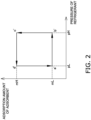
- the graph in Fig. 2 illustrates changes in an adsorption amount, which is the mass of the refrigerant adsorbed by the adsorbent per unit mass, and the pressure of the refrigerant adsorbed by the adsorbent in the heat pump cycle.
- the graph in Fig. 1 to 4 illustrate a refrigerant cycle a ⁇ b ⁇ c ⁇ d ⁇ a in the refrigerant circuit 11 and an adsorbent cycle a' ⁇ b' ⁇ c' ⁇ d' ⁇ a' in the adsorption circuit 12.
- the graph in Fig. 2 illustrates changes in an adsorption amount, which is the mass of the refrigerant adsorbed by the adsorbent per unit mass, and the pressure of the refrigerant
- FIG. 3 illustrates changes in the adsorption amount of the adsorbent and the enthalpy of the refrigerant adsorbed by the adsorbent in the heat pump cycle.
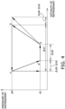
- the graph in Fig. 4 illustrates changes in the pressure of the refrigerant and the enthalpy of the refrigerant in the heat pump cycle. It is assumed that, in the refrigeration cycle apparatus 1, heat can freely transfer between the refrigerant circuit 11 and the adsorption circuit 12.
- the refrigerant In the refrigerant circuit 11, the refrigerant is compressed by the compressor 31 (a ⁇ b). In the adsorption circuit 12, the adsorbent is pressurized by the pressurizer 41 (a' ⁇ b'). Accordingly, the pressures of the refrigerant and adsorbent rise from pL to pH. In this process, a part Q1 of heat generated by adiabatic compression of the refrigerant is given to the adsorbent. In other words, the refrigerant gives heat to the adsorbent while being compressed, thereby being cooled. As a result, the temperatures of the refrigerant and adsorbent rise from TL to TH.
- the refrigerant is gradually adsorbed by the adsorbent while releasing heat Q2 (b' ⁇ c').
- the adsorption amount of the adsorbent increases from mL to mH.
- most of the refrigerant in the refrigerant circuit 11 is adsorbed by the adsorbent in the adsorption circuit 12.
- the refrigerant in the refrigerant circuit 11 moves to the adsorption circuit 12 and is adsorbed by the adsorbent.
- the adsorbent is depressurized by the depressurizer 42 (c' ⁇ d'). Accordingly, the pressure of the adsorbent drops from pH to pL.
- isenthalpic expansion of the refrigerant desorbed from the adsorbent causes the temperature of the adsorbent to drop from TH to TL.
- the depressurized adsorbent in the adsorption circuit 12 is cooled to give heat Q3 to the refrigerant in the refrigerant circuit 11.
- the heat exchanger 43 causes heat Q5 to be given from the adsorbent that has not yet been depressurized to the adsorbent that has not yet been pressurized.
- the refrigerant is gradually desorbed from the adsorbent while absorbing heat Q4 (d ⁇ a').
- the adsorption amount of the adsorbent decreases from mH to mL.
- most of the refrigerant adsorbed by the adsorbent in the adsorption circuit 12 is desorbed and flows into the refrigerant circuit 11.
- the refrigerant desorbed from the adsorbent in the adsorption circuit 12 moves to the refrigerant circuit 11.
- the pressure is pH, and the adsorption amount of the adsorbent increases from mL to mH.
- a desorption process in which the refrigerant is desorbed from the adsorbent, the pressure is pL, and the adsorption amount of the adsorbent decreases from mH to mL.
- the enthalpy decreases by ⁇ h1 in the adsorption process.
- the enthalpy increases by ⁇ h2.
- the heat Q2 released from the adsorption section 21 is proportional to ⁇ h1.
- the heat Q4 absorbed by the desorption section 22 is proportional to ⁇ h2.
- the amount of change in the enthalpy resulting from heat exchange by the heat exchanger 43 is represented by ⁇ h3.
- the amount of change in the enthalpy resulting from the adsorbent being heated is represented by ⁇ h4.
- the amount of change in the enthalpy resulting from the adsorbent being cooled is represented by ⁇ h5.
- the amount of change in the total enthalpy in the compression process of the refrigerant (a ⁇ b) is represented by ⁇ h4 - ⁇ h3.
- the amount of change in the total enthalpy in the depressurization process of the adsorbent (c' ⁇ d') is represented by ⁇ h5 - ⁇ h3.
- a change in the state of the refrigerant during adiabatic compression is indicated by a broken-line arrow
- a change in the state of the refrigerant during isenthalpic expansion is indicated by a dot-and-dash-line arrow.
- Fig. 5 illustrates isotherms during adsorption and desorption of the refrigerant that are suitable for the heat pump cycle of the refrigeration cycle apparatus 1.
- the isotherm at the temperature TH is indicated by a solid line
- the isotherm at the temperature TL is indicated by a dot-and-dash line.
- the isotherm at the temperature TH is preferably such that the adsorption amount of the adsorbent increases from mL to mH at a pressure between pL and pH.
- the isotherm at the temperature TL is preferably such that the adsorption amount of the adsorbent decreases from mH to mL at a pressure between pL and pH.
- a refrigeration cycle apparatus 101 of the present example includes a first refrigerant circuit 111 in which a primary refrigerant circulates and a second refrigerant circuit 112 in which a secondary refrigerant circulates.
- the first refrigerant circuit 111 is drawn by a thick line.
- the first refrigerant circuit 111 corresponds to the refrigerant circuit 11 in Fig. 1 .
- the refrigeration cycle apparatus 101 does not include a circuit in which an adsorbent circulates and which corresponds to the adsorption circuit 12 in Fig. 1 .
- an adsorbent is provided in the first refrigerant circuit 111.
- the secondary refrigerant is, for example, water.
- the first refrigerant circuit 111 includes a compressor 131, an expansion mechanism 132, a first adsorber 133, a second adsorber 134, and a switcher 135.
- the compressor 131 corresponds to the compressor 31 in Fig. 1 .
- the expansion mechanism 132 corresponds to the expansion mechanism 32 in Fig. 1 .
- the first adsorber 133 includes a first adsorbent 133a therein.
- the primary refrigerant that passes through the first adsorber 133 contacts the first adsorbent 133a.
- the first adsorbent 133a is accommodated in a container formed of a metal mesh, and is fixed inside the first adsorber 133, for example.
- the second adsorber 134 includes a second adsorbent 134a therein.
- the primary refrigerant that passes through the second adsorber 134 contacts the second adsorbent 134a.
- the second adsorbent 134a is accommodated in a container formed of a metal mesh, and is fixed inside the second adsorber 134, for example.
- the switcher 135 switches the flow direction of the primary refrigerant circulating in the first refrigerant circuit 111.
- the switcher 135 is, for example, a four-way switching valve.
- the switcher 135 switches between a first mode of the flow direction indicated by solid lines in Fig. 6 and a second mode of the flow direction indicated by broken lines in Fig. 6 .
- the discharge side of the compressor 131 is connected to the first adsorber 133, and the suction side of the compressor 131 is connected to the second adsorber 134.
- the discharge side of the compressor 131 is connected to the second adsorber 134, and the suction side of the compressor 131 is connected to the first adsorber 133.
- the second refrigerant circuit 112 includes a first fluid pump 141, a first heat exchanger 142, a first fan 143, a first tank 144, a second fluid pump 151, a second heat exchanger 152, a second fan 153, a second tank 154, and four channel changers 161 to 164.
- the first fluid pump 141 pumps the secondary refrigerant to the first heat exchanger 142.
- the first heat exchanger 142 exchanges heat between the secondary refrigerant and air.
- the first fan 143 sends the air that has exchanged heat in the first heat exchanger 142 to a predetermined place.
- the first tank 144 includes the first adsorber 133 therein, and exchanges heat between the primary refrigerant and the secondary refrigerant.
- the second fluid pump 151 pumps the secondary refrigerant to the second heat exchanger 152.
- the second heat exchanger 152 exchanges heat between the secondary refrigerant and air.
- the second fan 153 sends the air that has exchanged heat in the second heat exchanger 152 to a predetermined place.
- the second tank 154 includes the second adsorber 134 therein, and exchanges heat between the primary refrigerant and the secondary refrigerant.
- the channel changers 161 to 164 switch the connection state of the second refrigerant circuit 112 to change the channel through which the secondary refrigerant flows.
- the channel changers 161 to 164 are, for example, three-way switching valves.
- the channel changers 161 to 164 switch between a third mode of the connection state indicated by solid lines in Fig. 6 and a fourth mode of the connection state indicated by broken lines in Fig. 6 .
- the second refrigerant circuit 112 includes two circuits independent of each other in each of the third mode and the fourth mode.
- the two circuits of the second refrigerant circuit 112 are referred to as a first circulation circuit and a second circulation circuit.
- the direction in which the secondary refrigerant flows in the third mode is indicated by solid lines
- the direction in which the secondary refrigerant flows in the fourth mode is indicated by broken lines.
- the first circulation circuit is a circuit in which the first fluid pump 141, the first heat exchanger 142, the channel changer 161, the first tank 144, and the channel changer 162 are connected to each other.
- the second circulation circuit is a circuit in which the second fluid pump 151, the second heat exchanger 152, the channel changer 163, the second tank 154, and the channel changer 164 are connected to each other.
- the first circulation circuit is a circuit in which the first fluid pump 141, the first heat exchanger 142, the channel changer 161, the second tank 154, and the channel changer 162 are connected to each other.
- the second circulation circuit is a circuit in which the second fluid pump 151, the second heat exchanger 152, the channel changer 163, the first tank 144, and the channel changer 164 are connected to each other.
- the refrigeration cycle apparatus 101 is an air conditioning apparatus. It is assumed that the first heat exchanger 142 is an indoor heat exchanger and the second heat exchanger 152 is an outdoor heat exchanger.
- the secondary refrigerant heated by heat exchange with the primary refrigerant passes through the first heat exchanger 142.
- the secondary refrigerant circulating in the first circulation circuit including the first heat exchanger 142 needs to come into contact with, of the first adsorber 133 and the second adsorber 134, an adsorber including an adsorbent that adsorbs the primary refrigerant.
- the air heated by heat exchange with the secondary refrigerant in the first heat exchanger 142 is sent to a predetermined place by the first fan 143.
- a high-pressure primary refrigerant is introduced into the first adsorber 133, and the primary refrigerant is adsorbed by the first adsorbent 133a.
- a low-pressure primary refrigerant is introduced into the second adsorber 134, and the primary refrigerant is desorbed from the second adsorbent 134a.
- a high-pressure primary refrigerant is introduced into the second adsorber 134, and the primary refrigerant is adsorbed by the second adsorbent 134a.
- a low-pressure primary refrigerant is introduced into the first adsorber 133, and the primary refrigerant is desorbed from the first adsorbent 133a.
- the mode in the first mode, it is necessary to switch the mode to the third mode in which the secondary refrigerant passes through the first tank 144 including the first adsorber 133 and the first heat exchanger 142.
- the mode in the second mode, it is necessary to switch the mode to the fourth mode in which the secondary refrigerant passes through the second tank 154 including the second adsorber 134 and the first heat exchanger 142.
- the adsorption amount of the first adsorbent 133a in the first adsorber 133 reaches the maximum value mH, and the first adsorbent 133a becomes capable of adsorbing less primary refrigerant.
- the primary refrigerant is adsorbed by the second adsorbent 134a in the second adsorber 134, and the primary refrigerant is desorbed from the first adsorbent 133a in the first adsorber 133.
- the adsorption amount of the second adsorbent 134a in the second adsorber 134 reaches the maximum value mH, and the second adsorbent 134a becomes capable of adsorbing less primary refrigerant.
- the primary refrigerant is adsorbed by the first adsorbent 133a in the first adsorber 133, and the primary refrigerant is desorbed from the second adsorbent 134a in the second adsorber 134.
- the primary refrigerant can be adsorbed by the adsorbent in either one of the first adsorber 133 and the second adsorber 134, and the primary refrigerant can be constantly heated.
- the secondary refrigerant heated by heat exchange with the primary refrigerant can be constantly supplied to the first heat exchanger 142.
- a refrigeration cycle apparatus 201 of the present example includes a refrigerant circuit 211 in which a refrigerant circulates.
- the refrigerant circuit 211 has the functions of both the refrigerant circuit 11 and the adsorption circuit 12 in Fig. 1 .
- An adsorbent circulates in the refrigerant circuit 211 together with the refrigerant.
- a mixture of the refrigerant and the adsorbent circulates in the refrigerant circuit 211.
- the refrigerant circuit 211 includes a compressor 231, an expansion mechanism 232, a first heat exchanger 233, a second heat exchanger 234, a switcher 235, a first fan 236, and a second fan 237.
- the compressor 231 has the functions of both the compressor 31 and the pressurizer 41 in Fig. 1 .
- the expansion mechanism 232 has the functions of both the expansion mechanism 32 and the depressurizer 42 in Fig. 1 .
- the switcher 235 switches the flow direction of the mixture of the refrigerant and the adsorbent circulating in the refrigerant circuit 211.
- the switcher 235 is, for example, a four-way switching valve.
- the switcher 235 switches between a first mode of the flow direction indicated by solid lines in Fig. 7 and a second mode of the flow direction indicated by broken lines in Fig. 7 .
- the first mode the discharge side of the compressor 231 is connected to the first heat exchanger 233, and the suction side of the compressor 231 is connected to the second heat exchanger 234.
- the discharge side of the compressor 231 is connected to the second heat exchanger 234, and the suction side of the compressor 231 is connected to the first heat exchanger 233.
- a high-pressure refrigerant is adsorbed by the adsorbent in the first mode, and a low-pressure refrigerant is desorbed from the adsorbent in the second mode.
- a low-pressure refrigerant is desorbed from the adsorbent in the first mode, and a high-pressure refrigerant is adsorbed by the adsorbent in the second mode.
- the refrigerant is adsorbed by the adsorbent so as to be heated, or the refrigerant is desorbed from the adsorbent so as to be cooled.
- heat exchange is performed between the heated or cooled refrigerant and air in the first heat exchanger 233 and the second heat exchanger 234.
- the first fan 236 sends the air that has exchanged heat in the first heat exchanger 233 to a predetermined place.
- the second fan 237 sends the air that has exchanged heat in the second heat exchanger 234 to a predetermined place.
- the refrigeration cycle apparatus 201 in the process in which the mixture of the refrigerant and the adsorbent circulates in the refrigerant circuit 211, the refrigerant is heated or cooled, and the air that has exchanged heat with the refrigerant is sent to a predetermined place.
- the refrigeration cycle apparatus 201 is an air conditioning apparatus. It is assumed that the first heat exchanger 233 is an indoor heat exchanger and the second heat exchanger 234 is an outdoor heat exchanger.
- switching to the first mode causes the refrigerant to be adsorbed by the adsorbent and to be heated in the first heat exchanger 233.
- the air heated by heat exchange with the refrigerant is sent to a predetermined place by the first fan 236.
- a refrigeration cycle apparatus 301 of the present example includes a refrigerant circuit 311 in which a refrigerant circulates.
- the refrigerant circuit 311 has the functions of both the refrigerant circuit 11 and the adsorption circuit 12 in Fig. 1 .
- An adsorbent flows in a part of the refrigerant circuit 311 together with the refrigerant.
- a mixture of the refrigerant and the adsorbent circulates in the refrigerant circuit 311.
- the refrigerant circuit 311 includes a compressor 331, an expansion mechanism 332, a first heat exchanger 333, a second heat exchanger 334, a switcher 335, a first fan 336, a second fan 337, a pressurizer 341, and a separator 351.
- the compressor 331 corresponds to the compressor 31 in Fig. 1 .
- the pressurizer 341 corresponds to the pressurizer 41 in Fig. 1 .
- the expansion mechanism 332 has the functions of both the expansion mechanism 32 and the depressurizer 42 in Fig. 1 .
- the switcher 335 switches the flow direction of the mixture of the refrigerant and the adsorbent circulating in the refrigerant circuit 311.
- the switcher 335 is, for example, a four-way switching valve.
- the switcher 335 switches between a first mode of the flow direction indicated by solid lines in Fig. 8 and a second mode of the flow direction indicated by broken lines in Fig. 8 .
- the first mode the discharge sides of the compressor 331 and the pressurizer 341 are connected to the first heat exchanger 333, and the suction sides of the compressor 331 and the pressurizer 341 are connected to the second heat exchanger 334.
- the discharge sides of the compressor 331 and the pressurizer 341 are connected to the second heat exchanger 334, and the suction sides of the compressor 331 and the pressurizer 341 are connected to the first heat exchanger 333.
- the separator 351 is provided between the switcher 335 and the suction sides of the compressor 331 and the pressurizer 341.
- the separator 351 separates a mixture of a refrigerant in the low-pressure region and an adsorbent circulating in the refrigerant circuit 311 into the refrigerant and the adsorbent.
- the separator 351 performs separation into the refrigerant and the adsorbent by, for example, centrifugal separation.
- the refrigerant separated by the separator 351 is compressed by the compressor 331.
- the adsorbent separated by the separator 351 is pressurized by the pressurizer 341. As illustrated in Fig. 8 , the adsorbent pressurized by the pressurizer 341 merges with the refrigerant compressed by the compressor 331.
- the refrigerant and the adsorbent are sent to the switcher 335.
- the refrigerant circuit 311 branches at the separator 351 and merges between the compressor 331/pressurizer 341 and the switcher 335.
- a high-pressure refrigerant is adsorbed by the adsorbent in the first mode, and a low-pressure refrigerant is desorbed from the adsorbent in the second mode.
- a low-pressure refrigerant is desorbed from the adsorbent in the first mode, and a high-pressure refrigerant is adsorbed by the adsorbent in the second mode.
- the refrigerant is adsorbed by the adsorbent so as to be heated, or the refrigerant is desorbed from the adsorbent so as to be cooled.
- heat exchange is performed between the heated or cooled refrigerant and air in the first heat exchanger 333 and the second heat exchanger 334.
- the first fan 336 sends the air that has exchanged heat in the first heat exchanger 333 to a predetermined place.
- the second fan 337 sends the air that has exchanged heat in the second heat exchanger 334 to a predetermined place.
- the refrigeration cycle apparatus 301 in the process in which the mixture of the refrigerant and the adsorbent circulates in the refrigerant circuit 311, the refrigerant is heated or cooled, and the air that has exchanged heat with the refrigerant is sent to a predetermined place.
- the refrigeration cycle apparatus 301 is an air conditioning apparatus. It is assumed that the first heat exchanger 333 is an indoor heat exchanger and the second heat exchanger 334 is an outdoor heat exchanger.
- switching to the first mode causes the refrigerant to be adsorbed by the adsorbent and to be heated in the first heat exchanger 333.
- the air heated by heat exchange with the refrigerant is sent to a predetermined place by the first fan 336.
- a refrigeration cycle apparatus 401 of the present example includes a refrigerant circuit 411 in which a refrigerant circulates.
- the refrigerant circuit 411 has the functions of both the refrigerant circuit 11 and the adsorption circuit 12 in Fig. 1 .
- An adsorbent flows in a part of the refrigerant circuit 411 together with the refrigerant.
- a mixture of the refrigerant and the adsorbent circulates in the refrigerant circuit 411.
- the switcher 435 switches the flow direction of the mixture of the refrigerant and the adsorbent circulating in the refrigerant circuit 411.
- the switcher 435 is, for example, a four-way switching valve.
- the switcher 435 switches between a first mode of the flow direction indicated by solid lines in Fig. 9 and a second mode of the flow direction indicated by broken lines in Fig. 9 .
- the first mode the discharge sides of the compressor 431 and the pressurizer 441 are connected to the first heat exchanger 433, and the suction sides of the compressor 431 and the pressurizer 441 are connected to the second heat exchanger 434.
- the suction sides of the expansion mechanism 432 and the depressurizer 442 are connected to the first heat exchanger 433, and the discharge sides of the expansion mechanism 432 and the depressurizer 442 are connected to the second heat exchanger 434.
- the discharge sides of the compressor 431 and the pressurizer 441 are connected to the second heat exchanger 434, and the suction sides of the compressor 431 and the pressurizer 441 are connected to the first heat exchanger 433.
- the suction sides of the expansion mechanism 432 and the depressurizer 442 are connected to the second heat exchanger 434, and the discharge sides of the expansion mechanism 432 and the depressurizer 442 are connected to the first heat exchanger 433.
- the first separator 451 is provided between the switcher 435 and the suction sides of the compressor 431 and the pressurizer 441.
- the second separator 452 is provided between the first heat exchanger 433 and the suction sides of the expansion mechanism 432 and the depressurizer 442 in the first mode.
- the first separator 451 separates a mixture of a refrigerant in the low-pressure region and an adsorbent circulating in the refrigerant circuit 411 into the refrigerant and the adsorbent.
- the first separator 451 performs separation into the refrigerant and the adsorbent by, for example, centrifugal separation.
- the refrigerant separated by the first separator 451 is compressed by the compressor 431.
- the adsorbent separated by the first separator 451 is pressurized by the pressurizer 441. As illustrated in Fig. 9 , the adsorbent pressurized by the pressurizer 441 merges with the refrigerant compressed by the compressor 431.
- the refrigerant and the adsorbent are sent to the switcher 435.
- the refrigerant circuit 411 branches at the first separator 451 and merges between the compressor 431/pressurizer 441 and the switcher 435.
- the second separator 452 separates a mixture of a refrigerant in the high-pressure region and an adsorbent circulating in the refrigerant circuit 411 into the refrigerant and the adsorbent in the first mode.
- the second separator 452 performs separation into the refrigerant and the adsorbent by, for example, centrifugal separation.
- the refrigerant separated by the second separator 452 is decompressed by the expansion mechanism 432.
- the adsorbent separated by the second separator 452 is depressurized by the depressurizer 442. As illustrated in Fig. 9 , the adsorbent depressurized by the depressurizer 442 merges with the refrigerant decompressed by the expansion mechanism 432.
- the refrigerant and the adsorbent are sent to the second heat exchanger 434.
- the refrigerant circuit 411 branches at the second separator 452 and merges between the expansion mechanism 432/depressurizer 442 and the second heat exchanger 434 in the first mode.
- the depressurizer 442 is closed, and the mixture of the refrigerant and the adsorbent is decompressed by the expansion mechanism 432 and then sent to the first heat exchanger 433 through the second separator 452.
- a high-pressure refrigerant is adsorbed by the adsorbent in the first mode, and a low-pressure refrigerant is desorbed from the adsorbent in the second mode.
- a low-pressure refrigerant is desorbed from the adsorbent in the first mode, and a high-pressure refrigerant is adsorbed by the adsorbent in the second mode.
- the refrigerant is adsorbed by the adsorbent so as to be heated, or the refrigerant is desorbed from the adsorbent so as to be cooled.
- heat exchange is performed between the heated or cooled refrigerant and air in the first heat exchanger 433 and the second heat exchanger 434.
- the first fan 436 sends the air that has exchanged heat in the first heat exchanger 433 to a predetermined place.
- the second fan 437 sends the air that has exchanged heat in the second heat exchanger 434 to a predetermined place.
- the refrigeration cycle apparatus 401 in the process in which the mixture of the refrigerant and the adsorbent circulates in the refrigerant circuit 411, the refrigerant is heated or cooled, and the air that has exchanged heat with the refrigerant is sent to a predetermined place.
- the refrigeration cycle apparatus 401 is an air conditioning apparatus. It is assumed that the first heat exchanger 433 is an indoor heat exchanger and the second heat exchanger 434 is an outdoor heat exchanger.
- switching to the first mode causes the refrigerant to be adsorbed by the adsorbent and to be heated in the first heat exchanger 433.
- the air heated by heat exchange with the refrigerant is sent to a predetermined place by the first fan 436.
- the refrigerant circuit 511 includes a compressor 531, an expansion mechanism 532, a first heat exchanger 533, a second heat exchanger 534, and a first switcher 535.
- the compressor 531 corresponds to the compressor 31 in Fig. 1 .
- the expansion mechanism 532 corresponds to the expansion mechanism 32 in Fig. 1 .
- the first switcher 535 switches the flow direction of a refrigerant circulating in the refrigerant circuit 511.
- the first switcher 535 is, for example, a four-way switching valve.
- the first switcher 535 switches between a first mode of the flow direction indicated by solid lines in Fig. 10 and a second mode of the flow direction indicated by broken lines in Fig. 10 .
- the discharge side of the compressor 531 is connected to the first heat exchanger 533, and the suction side of the compressor 531 is connected to the second heat exchanger 534.
- the discharge side of the compressor 531 is connected to the second heat exchanger 534, and the suction side of the compressor 531 is connected to the first heat exchanger 533.
- the adsorption circuit 512 includes a pressurizer 541, a depressurizer 542, a third heat exchanger 543, a fourth heat exchanger 544, and a second switcher 545.
- the pressurizer 541 corresponds to the pressurizer 41 in Fig. 1 .
- the depressurizer 542 corresponds to the depressurizer 42 in Fig. 1 .
- the second switcher 545 switches the flow direction of an adsorbent circulating in the adsorption circuit 512.
- the second switcher 545 is, for example, a four-way switching valve.
- the second switcher 545 switches between the first mode of the flow direction indicated by the solid lines in Fig. 10 and the second mode of the flow direction indicated by the broken lines in Fig. 10 .
- the discharge side of the pressurizer 541 is connected to the third heat exchanger 543, and the suction side of the pressurizer 541 is connected to the fourth heat exchanger 544.
- the discharge side of the pressurizer 541 is connected to the fourth heat exchanger 544, and the suction side of the pressurizer 541 is connected to the third heat exchanger 543.
- the second switcher 545 switches between the first mode and the second mode in conjunction with the first switcher 535.
- the first mixers 513 and the second mixers 514 mix the refrigerant flowing in the refrigerant circuit 511 and the adsorbent flowing in the adsorption circuit 512.
- the pair of first mixers 513 are provided on the upstream side and the downstream side of the first heat exchanger 533 and the third heat exchanger 543.
- the pair of second mixers 514 are provided on the upstream side and the downstream side of the second heat exchanger 534 and the fourth heat exchanger 544.
- the first mixers 513 and the second mixers 514 each include, for example, a permeable member that allows a refrigerant to pass therethrough and does not allow an adsorbent to pass therethrough.
- the permeable member is, for example, a gas permeable film.
- the inside of each of the first mixers 513 and the second mixers 514 is partitioned by the permeable member into a space which is a part of the refrigerant circuit 511 and a space which is a part of the adsorption circuit 512.
- the refrigerant flowing in the refrigerant circuit 511 passes through the permeable member and come into contact with the adsorbent flowing in the adsorption circuit 512.
- the adsorbent flowing in the adsorption circuit 512 is unable to pass through the permeable member. Accordingly, in the first mixers 513 and the second mixers 514, the adsorbent adsorbs and desorbs the refrigerant that has passed through the permeable member.
- a high-pressure refrigerant is adsorbed by the adsorbent in the first mode, and a low-pressure refrigerant is desorbed from the adsorbent in the second mode.
- a low-pressure refrigerant is desorbed from the adsorbent in the first mode, and a high-pressure refrigerant is adsorbed by the adsorbent in the second mode.
- the refrigerant is adsorbed by the adsorbent and thereby the refrigerant and the adsorbent are heated, or the refrigerant is desorbed from the adsorbent and thereby the refrigerant and the adsorbent are cooled.
- heat exchange is performed between the heated or cooled refrigerant and adsorbent and air in the first heat exchanger 533, the second heat exchanger 534, the third heat exchanger 543, and the fourth heat exchanger 544.
- heat exchange between the heated refrigerant and air is performed in the first heat exchanger 533, and heat exchange between the heated adsorbent and air is performed in the third heat exchanger 543.
- heat exchange between the cooled refrigerant and air is performed in the second heat exchanger 534, and heat exchange between the cooled adsorbent and air is performed in the fourth heat exchanger 544.
- heat exchange between the cooled refrigerant and air is performed in the first heat exchanger 533, and heat exchange between the cooled adsorbent and air is performed in the third heat exchanger 543.
- heat exchange between the heated refrigerant and air is performed in the second heat exchanger 534, and heat exchange between the heated adsorbent and air is performed in the fourth heat exchanger 544.
- the first fan 515 sends the air that has exchanged heat in the first heat exchanger 533 and the third heat exchanger 543 to a predetermined place.
- the second fan 516 sends the air that has exchanged heat in the second heat exchanger 534 and the fourth heat exchanger 544 to a predetermined place.
- the pair of first mixers 513, the first fan 515, the first heat exchanger 533, and the third heat exchanger 543 correspond to the adsorption section 21 in Fig. 1 in the first mode, and correspond to the desorption section 22 in Fig. 1 in the second mode.
- the pair of second mixers 514, the second fan 516, the second heat exchanger 534, and the fourth heat exchanger 544 correspond to the desorption section 22 in Fig. 1 in the first mode, and correspond to the adsorption section 21 in Fig. 1 in the second mode.
- the refrigeration cycle apparatus 501 in the process in which the refrigerant circulates in the refrigerant circuit 511 and the adsorbent circulates in the adsorption circuit 512, the refrigerant and the adsorbent are heated or cooled, and the air that has exchanged heat with the refrigerant and the adsorbent is sent to a predetermined place.
- the refrigeration cycle apparatus 501 is an air conditioning apparatus. It is assumed that the first heat exchanger 533 and the third heat exchanger 543 are indoor heat exchangers and the second heat exchanger 534 and the fourth heat exchanger 544 are outdoor heat exchangers.
- switching to the first mode causes the refrigerant to be adsorbed by the adsorbent and causes the refrigerant and the adsorbent to be heated in the first mixers 513.
- the air heated by heat exchange with the refrigerant and the adsorbent is sent to a predetermined place by the first fan 515.
- the refrigeration cycle apparatus 1 can be operated at an operating pressure lower than that of the existing refrigeration cycle apparatus, and thus the manufacturing cost and the operation cost can be reduced.
- the lower design pressure makes it possible to make members such as the casing of the compressor compact, and improve the reliability of the system.
- the refrigeration cycle apparatus 1 when the refrigeration cycle apparatus 1 is an air conditioning apparatus, the refrigeration cycle apparatus 1 is capable of increasing the cooling and heating capacity by using the adsorption heat and the desorption heat of the refrigerant for cooling and heating.
- the refrigeration cycle apparatus 1 is capable of improving the efficiency of the refrigeration cycle and reducing the operation cost as compared with the existing refrigeration cycle apparatus.
- the refrigerant circuit 411 includes the first separator 451. However, the refrigerant circuit 411 need not include the first separator 451. In this case, as illustrated in Fig. 11 , the refrigerant circuit 411 includes the compressor 431 and does not include the pressurizer 441. Similarly to the compressor 231 of the second modification, the compressor 431 of the present modification has the functions of both the compressor 31 and the pressurizer 41 in Fig. 1 .
- the adsorbent used in the refrigeration cycle apparatuses 1, 101, 201, 301, 401, and 501 is a metal-organic framework.
- a material other than a metal-organic framework may be used as the adsorbent.
Landscapes
- Engineering & Computer Science (AREA)
- Physics & Mathematics (AREA)
- Mechanical Engineering (AREA)
- Thermal Sciences (AREA)
- General Engineering & Computer Science (AREA)
- Sorption Type Refrigeration Machines (AREA)
- Compression-Type Refrigeration Machines With Reversible Cycles (AREA)
Abstract
A refrigeration cycle apparatus (1, 101, 201, 301, 401, 501) includes a refrigerant circuit (11, 111, 211, 311, 411, 511) and an adsorbent. The refrigerant circuit includes a compressor (31, 131, 231, 331, 431, 531) that compresses a refrigerant. The refrigerant circuit constitutes a vapor compression refrigeration cycle in which the refrigerant circulates. The adsorbent adsorbs and desorbs the refrigerant circulating in the refrigerant circuit. The adsorbent adsorbs and desorbs the refrigerant in accordance with a change in a pressure of the refrigerant circulating in the refrigerant circuit.
Description
- The present disclosure relates to a refrigeration cycle apparatus.
- Hitherto, a hybrid refrigeration system employing a combination of a vapor compression refrigeration cycle and an adsorption refrigeration cycle has been used. Patent Literature 1 (International Publication No.
2009/145278 ) discloses a hybrid refrigeration system in which a pair of adsorbers of an adsorption refrigeration cycle are alternately cooled and heated to alternately repeat adsorption and desorption of a refrigerant in order to reduce a mechanical work load of a compressor of a vapor compression refrigeration cycle. - A hybrid refrigeration system that controls adsorption and desorption of a refrigerant in an adsorption refrigeration cycle by using a change in the pressure of a refrigerant circulating in a vapor compression refrigeration cycle is not conventionally used.
- A refrigeration cycle apparatus according to a first aspect includes a first unit and an adsorbent. The first unit constitutes a refrigeration cycle in which a refrigerant circulates. The adsorbent adsorbs and desorbs the refrigerant circulating in the first unit. The adsorbent adsorbs and desorbs the refrigerant in accordance with a change in a pressure of the refrigerant circulating in the first unit.
- The refrigeration cycle apparatus according to the first aspect has a lower operating pressure than a refrigeration cycle apparatus that does not have an adsorbent, and is capable of using the adsorption heat and desorption heat of the refrigerant. Thus, the refrigeration cycle apparatus according to the first aspect is capable of reducing the cost and improving the efficiency of the refrigeration cycle.
- A refrigeration cycle apparatus according to a second aspect includes a first unit and an adsorbent. The first unit includes a compressor that compresses a refrigerant and constitutes a vapor compression refrigeration cycle in which the refrigerant circulates. The adsorbent adsorbs and desorbs the refrigerant circulating in the first unit. The adsorbent adsorbs and desorbs the refrigerant in accordance with a change in a pressure of the refrigerant circulating in the first unit.
- The refrigeration cycle apparatus according to the second aspect has a lower operating pressure than a refrigeration cycle apparatus that has a vapor compression refrigeration cycle and does not have an adsorbent, and is capable of using the adsorption heat and desorption heat of the refrigerant. Thus, the refrigeration cycle apparatus according to the second aspect is capable of reducing the cost and improving the efficiency of the refrigeration cycle.
- A refrigeration cycle apparatus according to a third aspect is the refrigeration cycle apparatus according to the second aspect, in which the first unit further includes an expansion mechanism that decompresses the refrigerant, a high-pressure region, and a low-pressure region. In the high-pressure region, the refrigerant that has been compressed by the compressor and that has not yet been decompressed by the expansion mechanism flows. In the low-pressure region, the refrigerant that has been decompressed by the expansion mechanism and that has not yet been compressed by the compressor flows. The adsorbent adsorbs the refrigerant in the high-pressure region and desorbs the refrigerant in the low-pressure region.
- A refrigeration cycle apparatus according to a fourth aspect is the refrigeration cycle apparatus according to the third aspect, in which the refrigeration cycle apparatus further includes a first adsorber including the adsorbent, a second adsorber including the adsorbent, and a switcher. The switcher alternately switches between a first mode and a second mode. In the first mode, the switcher introduces the refrigerant in the high-pressure region into the first adsorber to cause the adsorbent in the first adsorber to adsorb the refrigerant, and introduces the refrigerant in the low-pressure region into the second adsorber to cause the adsorbent in the second adsorber to desorb the refrigerant. In the second mode, the switcher introduces the refrigerant in the low-pressure region into the first adsorber to cause the adsorbent in the first adsorber to desorb the refrigerant, and introduces the refrigerant in the high-pressure region into the second adsorber to cause the adsorbent in the second adsorber to adsorb the refrigerant.
- A refrigeration cycle apparatus according to a fifth aspect is the refrigeration cycle apparatus according to the third aspect, in which the adsorbent circulates in the first unit together with the refrigerant.
- A refrigeration cycle apparatus according to a sixth aspect is the refrigeration cycle apparatus according to the fifth aspect, in which the refrigeration cycle apparatus further includes a separator that separates the refrigerant circulating in the first unit and the adsorbent circulating in the first unit from each other. After being separated from the refrigerant by the separator, the adsorbent merges with the refrigerant compressed by the compressor or the refrigerant decompressed by the expansion mechanism.
- A refrigeration cycle apparatus according to a seventh aspect is the refrigeration cycle apparatus according to the sixth aspect, in which the refrigeration cycle apparatus further includes a pressurizer. The separator separates the refrigerant in the low-pressure region and the adsorbent from each other. The pressurizer pressurizes the adsorbent separated from the refrigerant by the separator.
- A refrigeration cycle apparatus according to an eighth aspect is the refrigeration cycle apparatus according to the sixth aspect or the seventh aspect, in which the refrigeration cycle apparatus further includes a depressurizer. The separator separates the refrigerant in the high-pressure region and the adsorbent from each other. The depressurizer depressurizes the adsorbent separated from the refrigerant by the separator.
- A refrigeration cycle apparatus according to a ninth aspect is the refrigeration cycle apparatus according to any one of the sixth to eighth aspects, in which the separator separates the refrigerant and the adsorbent from each other by centrifugal separation.
- A refrigeration cycle apparatus according to a tenth aspect is the refrigeration cycle apparatus according to the third aspect, in which the refrigeration cycle apparatus further includes a second unit and a mixer. The second unit includes a pressurizer that pressurizes the adsorbent and a depressurizer that depressurizes the adsorbent. The second unit constitutes an adsorption refrigeration cycle in which the adsorbent circulates. The mixer mixes the refrigerant flowing in the first unit and the adsorbent flowing in the second unit. The adsorbent adsorbs and desorbs the refrigerant in the mixer.
- A refrigeration cycle apparatus according to an eleventh aspect is the refrigeration cycle apparatus according to the tenth aspect, in which the mixer includes a permeable member. The permeable member is a member that allows the refrigerant to pass therethrough and does not allow the adsorbent to pass therethrough. The adsorbent adsorbs and desorbs the refrigerant that has passed through the permeable member in the mixer.
- A refrigeration cycle apparatus according to a twelfth aspect is the refrigeration cycle apparatus according to any one of the first to eleventh aspects, in which the adsorbent includes a metal-organic framework including a metal ion and an organic ligand.
- A refrigeration cycle apparatus according to a thirteenth aspect is the refrigeration cycle apparatus according to any one of the first to twelfth aspects, in which the refrigerant is selected from the group consisting of carbon dioxide, ammonia, and propane.
-
-
Fig. 1 is a schematic diagram of a hybrid cycle included in a refrigeration cycle apparatus. -
Fig. 2 is a graph illustrating the relationship between the adsorption amount of an adsorbent and the pressure of a refrigerant. -
Fig. 3 is a graph illustrating the relationship between the adsorption amount of an adsorbent and the enthalpy of a refrigerant. -
Fig. 4 is a graph illustrating the relationship between the pressure of a refrigerant and the enthalpy of the refrigerant. -
Fig. 5 is a graph illustrating isotherms of a refrigerant adsorbed by an adsorbent. -
Fig. 6 is a configuration diagram of a refrigeration cycle apparatus according to a first example. -
Fig. 7 is a configuration diagram of a refrigeration cycle apparatus according to a second example. -
Fig. 8 is a configuration diagram of a refrigeration cycle apparatus according to a third example. -
Fig. 9 is a configuration diagram of a refrigeration cycle apparatus according to a fourth example. -
Fig. 10 is a configuration diagram of a refrigeration cycle apparatus according to a fifth example. -
Fig. 11 is a configuration diagram of a refrigeration cycle apparatus according to modification A. - A
refrigeration cycle apparatus 1 includes a hybrid cycle in which a vapor compression cycle and an adsorption cycle are combined. The vapor compression cycle is a vapor compression refrigeration cycle, and is a heat pump cycle that uses transfer of latent heat generated when a refrigerant evaporates and condenses. The adsorption cycle is an adsorption refrigeration cycle, and is a heat pump cycle that uses transfer of latent heat generated when a refrigerant is adsorbed by an adsorbent and when a refrigerant is desorbed from an adsorbent. Therefrigeration cycle apparatus 1 is, for example, an air conditioning apparatus and a refrigeration apparatus. - As illustrated in
Fig. 1 , therefrigeration cycle apparatus 1 includes arefrigerant circuit 11 and anadsorption circuit 12. Therefrigerant circuit 11 constitutes a vapor compression cycle in which a refrigerant circulates. Theadsorption circuit 12 constitutes an adsorption cycle in which an adsorbent circulates. - The
refrigeration cycle apparatus 1 may include only one circuit having the function of at least one of therefrigerant circuit 11 and theadsorption circuit 12. In this case, therefrigeration cycle apparatus 1 may include a circuit in which a mixture of a refrigerant and an adsorbent circulates. Alternatively, therefrigeration cycle apparatus 1 may include a circuit in which only a refrigerant circulates and which includes a mechanism for bringing a circulating refrigerant into contact with an adsorbent. In this case, the adsorbent is not circulated. - The
refrigeration cycle apparatus 1 may include two circuits composed of a circuit having the function of therefrigerant circuit 11 and a circuit having the function of theadsorption circuit 12. In this case, therefrigeration cycle apparatus 1 includes a mechanism for bringing the refrigerant circulating in therefrigerant circuit 11 into contact with the adsorbent circulating in theadsorption circuit 12. InFig. 1 , therefrigerant circuit 11 and theadsorption circuit 12 are illustrated as independent circuits for the sake of description. - The
refrigeration cycle apparatus 1 includes anadsorption section 21 and adesorption section 22. Theadsorption section 21 and thedesorption section 22 each include a part of therefrigerant circuit 11 and a part of theadsorption circuit 12. In theadsorption section 21 and thedesorption section 22, a refrigerant is able to freely move between therefrigerant circuit 11 and theadsorption circuit 12. An adsorbent is unable to move between therefrigerant circuit 11 and theadsorption circuit 12. In theadsorption section 21, the refrigerant that has flowed into theadsorption circuit 12 from therefrigerant circuit 11 is adsorbed by the adsorbent flowing in theadsorption circuit 12. In thedesorption section 22, the refrigerant desorbed from the adsorbent flowing in theadsorption circuit 12 flows into therefrigerant circuit 11 from theadsorption circuit 12. - The
refrigerant circuit 11 includes acompressor 31 and anexpansion mechanism 32. Thecompressor 31 compresses the refrigerant circulating in therefrigerant circuit 11. Theexpansion mechanism 32 decompresses the refrigerant circulating in therefrigerant circuit 11. Thecompressor 31 is, for example, a rotary compressor. Theexpansion mechanism 32 is, for example, an electronic expansion valve. In therefrigerant circuit 11, a refrigerant is compressed by thecompressor 31, passes through theadsorption section 21, is decompressed by theexpansion mechanism 32, passes through thedesorption section 22, and is compressed again by thecompressor 31. - The
refrigerant circuit 11 includes a high-pressure region and a low-pressure region. In the high-pressure region, a refrigerant that has been compressed by thecompressor 31 and that has not yet been decompressed by theexpansion mechanism 32 flows. In the low-pressure region, a refrigerant that has been decompressed by theexpansion mechanism 32 and that has not yet been compressed by thecompressor 31 flows. The high-pressure region corresponds to a part of therefrigerant circuit 11 included in theadsorption section 21. The low-pressure region corresponds to a part of therefrigerant circuit 11 included in thedesorption section 22. - The refrigerant circulating in the
refrigerant circuit 11 is carbon dioxide. The refrigerant may be ammonia or propane. - The
adsorption circuit 12 includes apressurizer 41 and adepressurizer 42. Thepressurizer 41 pressurizes the adsorbent circulating in theadsorption circuit 12. Thedepressurizer 42 depressurizes the adsorbent circulating in theadsorption circuit 12. Thepressurizer 41 is, for example, a powder pump. Thedepressurizer 42 is, for example, a powder valve. In theadsorption circuit 12, an adsorbent is pressurized by thepressurizer 41, passes through theadsorption section 21, is depressurized by thedepressurizer 42, passes through thedesorption section 22, and is pressurized again by thepressurizer 41. Depending on the configuration of therefrigeration cycle apparatus 1, theadsorption circuit 12 need not include thepressurizer 41 and thedepressurizer 42. - The
adsorption circuit 12 may further include aheat exchanger 43. Theheat exchanger 43 exchanges heat between the upstream side of thepressurizer 41 and the upstream side of thedepressurizer 42. Theheat exchanger 43 gives a part of the heat of the adsorbent flowing between theadsorption section 21 and thedepressurizer 42 to the adsorbent flowing between thedesorption section 22 and thepressurizer 41. - The adsorbent circulating in the
adsorption circuit 12 includes a metal-organic framework including a metal ion and an organic ligand. A metal-organic framework (MOF) is a porous material that has a very large specific surface and that is obtained by a reaction of a metal ion and an organic ligand. In the MOF, an organic ligand is linked to a metal ion, and thereby a polymer structure having innumerable voids therein is obtained. In the MOF, the void diameter and topology can be adjusted by selecting and combining a metal ion and an organic ligand. In the MOF, the void diameter can be adjusted and a target substance can be selectively adsorbed by selecting and combining a metal ion and an organic ligand. The MOF is used as, for example, a porous material having a function of selectively storing and separating molecules and ions. In the present embodiment, the MOF is used as an adsorbent for adsorbing and desorbing a refrigerant. The MOF includes, for example, MOF-5 and MOF-200. The adsorbent is, for example, a powder of an MOF. - The adsorbent adsorbs and desorbs the refrigerant circulating in the
refrigerant circuit 11. The adsorbent adsorbs and desorbs the refrigerant in accordance with a change in the pressure of the refrigerant circulating in therefrigerant circuit 11. Specifically, the adsorbent adsorbs the refrigerant under high pressure, and desorbs the refrigerant under low pressure. - It is assumed that the high-pressure region of the
refrigerant circuit 11 is filled with a refrigerant having a pressure pH and a temperature TH. It is assumed that the low-pressure region of therefrigerant circuit 11 is filled with a refrigerant having a pressure pL and a temperature TL. The pressure pH is higher than the pressure pL. The temperature TH is higher than the temperature TL. The adsorbent adsorbs the refrigerant in the high-pressure region of therefrigerant circuit 11. The adsorbent desorbs the refrigerant in the low-pressure region of therefrigerant circuit 11. In theadsorption section 21, the refrigerant flowing in the high-pressure region of therefrigerant circuit 11 flows into theadsorption circuit 12 and is adsorbed by the adsorbent. In thedesorption section 22, the refrigerant desorbed from the adsorbent flowing in theadsorption circuit 12 flows into the low-pressure region of therefrigerant circuit 11. - The operation of a heat pump cycle of the
refrigeration cycle apparatus 1 will be described with reference toFigs. 1 to 4. Figs. 1 to 4 illustrate a refrigerant cycle a→b→c→d→a in therefrigerant circuit 11 and an adsorbent cycle a'→b'→c'→d'→a' in theadsorption circuit 12. The graph inFig. 2 illustrates changes in an adsorption amount, which is the mass of the refrigerant adsorbed by the adsorbent per unit mass, and the pressure of the refrigerant adsorbed by the adsorbent in the heat pump cycle. The graph inFig. 3 illustrates changes in the adsorption amount of the adsorbent and the enthalpy of the refrigerant adsorbed by the adsorbent in the heat pump cycle. The graph inFig. 4 illustrates changes in the pressure of the refrigerant and the enthalpy of the refrigerant in the heat pump cycle. It is assumed that, in therefrigeration cycle apparatus 1, heat can freely transfer between therefrigerant circuit 11 and theadsorption circuit 12. - In the
refrigerant circuit 11, the refrigerant is compressed by the compressor 31 (a→b). In theadsorption circuit 12, the adsorbent is pressurized by the pressurizer 41 (a'→b'). Accordingly, the pressures of the refrigerant and adsorbent rise from pL to pH. In this process, a part Q1 of heat generated by adiabatic compression of the refrigerant is given to the adsorbent. In other words, the refrigerant gives heat to the adsorbent while being compressed, thereby being cooled. As a result, the temperatures of the refrigerant and adsorbent rise from TL to TH. - Subsequently, in the
adsorption section 21, the refrigerant is gradually adsorbed by the adsorbent while releasing heat Q2 (b'→c'). In this process, the adsorption amount of the adsorbent increases from mL to mH. As a result, in theadsorption section 21, most of the refrigerant in therefrigerant circuit 11 is adsorbed by the adsorbent in theadsorption circuit 12. As indicated by hatched arrows in theadsorption section 21 inFig. 1 , in theadsorption section 21, the refrigerant in therefrigerant circuit 11 moves to theadsorption circuit 12 and is adsorbed by the adsorbent. - Subsequently, in the
adsorption circuit 12, the adsorbent is depressurized by the depressurizer 42 (c'→d'). Accordingly, the pressure of the adsorbent drops from pH to pL. In this process, isenthalpic expansion of the refrigerant desorbed from the adsorbent causes the temperature of the adsorbent to drop from TH to TL. Due to the difference in temperature between the refrigerant and the adsorbent, the depressurized adsorbent in theadsorption circuit 12 is cooled to give heat Q3 to the refrigerant in therefrigerant circuit 11. Theheat exchanger 43 causes heat Q5 to be given from the adsorbent that has not yet been depressurized to the adsorbent that has not yet been pressurized. - Subsequently, in the
desorption section 22, the refrigerant is gradually desorbed from the adsorbent while absorbing heat Q4 (d→a'). In this process, the adsorption amount of the adsorbent decreases from mH to mL. As a result, most of the refrigerant adsorbed by the adsorbent in theadsorption circuit 12 is desorbed and flows into therefrigerant circuit 11. As indicated by hatched arrows in thedesorption section 22 inFig. 1 , in thedesorption section 22, the refrigerant desorbed from the adsorbent in theadsorption circuit 12 moves to therefrigerant circuit 11. - As illustrated in
Fig. 2 , in an adsorption process (b'→c') in which the refrigerant is adsorbed by the adsorbent, the pressure is pH, and the adsorption amount of the adsorbent increases from mL to mH. In a desorption process (d'→a') in which the refrigerant is desorbed from the adsorbent, the pressure is pL, and the adsorption amount of the adsorbent decreases from mH to mL. As illustrated inFig. 3 , the enthalpy decreases by Δh1 in the adsorption process. In the desorption process, the enthalpy increases by Δh2. In the adsorption process, the heat Q2 released from theadsorption section 21 is proportional to Δh1. In the desorption process, the heat Q4 absorbed by thedesorption section 22 is proportional to Δh2. - The amount of change in the enthalpy resulting from heat exchange by the
heat exchanger 43 is represented by Δh3. In the pressurization process of the adsorbent (a'→b'), the amount of change in the enthalpy resulting from the adsorbent being heated is represented by Δh4. In the depressurization process of the adsorbent (c'→d'), the amount of change in the enthalpy resulting from the adsorbent being cooled is represented by Δh5. As illustrated inFig. 4 , the amount of change in the total enthalpy in the compression process of the refrigerant (a→b) is represented by Δh4 - Δh3. The amount of change in the total enthalpy in the depressurization process of the adsorbent (c'→d') is represented by Δh5 - Δh3. InFig. 4 , a change in the state of the refrigerant during adiabatic compression is indicated by a broken-line arrow, and a change in the state of the refrigerant during isenthalpic expansion is indicated by a dot-and-dash-line arrow. -
Fig. 5 illustrates isotherms during adsorption and desorption of the refrigerant that are suitable for the heat pump cycle of therefrigeration cycle apparatus 1. InFig. 5 , the isotherm at the temperature TH is indicated by a solid line, and the isotherm at the temperature TL is indicated by a dot-and-dash line. In the adsorption process (b'→c'), when the refrigerant is adsorbed by the adsorbent at the pressure pH and the temperature TH, the isotherm at the temperature TH is preferably such that the adsorption amount of the adsorbent increases from mL to mH at a pressure between pL and pH. In the desorption process (d'→a'), when the refrigerant is desorbed from the adsorbent at the pressure pL and the temperature TL, the isotherm at the temperature TL is preferably such that the adsorption amount of the adsorbent decreases from mH to mL at a pressure between pL and pH. - First to fifth examples, which are specific configurations of the
refrigeration cycle apparatus 1 illustrated inFig. 1 , will be described with reference toFigs. 6 to 10 . - As illustrated in
Fig. 6 , arefrigeration cycle apparatus 101 of the present example includes a firstrefrigerant circuit 111 in which a primary refrigerant circulates and a secondrefrigerant circuit 112 in which a secondary refrigerant circulates. InFig. 6 , the firstrefrigerant circuit 111 is drawn by a thick line. The firstrefrigerant circuit 111 corresponds to therefrigerant circuit 11 inFig. 1 . Therefrigeration cycle apparatus 101 does not include a circuit in which an adsorbent circulates and which corresponds to theadsorption circuit 12 inFig. 1 . In therefrigeration cycle apparatus 101, an adsorbent is provided in the firstrefrigerant circuit 111. The secondary refrigerant is, for example, water. - The first
refrigerant circuit 111 includes acompressor 131, anexpansion mechanism 132, afirst adsorber 133, asecond adsorber 134, and aswitcher 135. Thecompressor 131 corresponds to thecompressor 31 inFig. 1 . Theexpansion mechanism 132 corresponds to theexpansion mechanism 32 inFig. 1 . - The
first adsorber 133 includes afirst adsorbent 133a therein. The primary refrigerant that passes through thefirst adsorber 133 contacts thefirst adsorbent 133a. Thefirst adsorbent 133a is accommodated in a container formed of a metal mesh, and is fixed inside thefirst adsorber 133, for example. - The
second adsorber 134 includes asecond adsorbent 134a therein. The primary refrigerant that passes through thesecond adsorber 134 contacts thesecond adsorbent 134a. Thesecond adsorbent 134a is accommodated in a container formed of a metal mesh, and is fixed inside thesecond adsorber 134, for example. - The
switcher 135 switches the flow direction of the primary refrigerant circulating in the firstrefrigerant circuit 111. Theswitcher 135 is, for example, a four-way switching valve. Theswitcher 135 switches between a first mode of the flow direction indicated by solid lines inFig. 6 and a second mode of the flow direction indicated by broken lines inFig. 6 . In the first mode, the discharge side of thecompressor 131 is connected to thefirst adsorber 133, and the suction side of thecompressor 131 is connected to thesecond adsorber 134. In the second mode, the discharge side of thecompressor 131 is connected to thesecond adsorber 134, and the suction side of thecompressor 131 is connected to thefirst adsorber 133. - The second
refrigerant circuit 112 includes afirst fluid pump 141, afirst heat exchanger 142, afirst fan 143, afirst tank 144, asecond fluid pump 151, asecond heat exchanger 152, asecond fan 153, asecond tank 154, and fourchannel changers 161 to 164. - The
first fluid pump 141 pumps the secondary refrigerant to thefirst heat exchanger 142. Thefirst heat exchanger 142 exchanges heat between the secondary refrigerant and air. Thefirst fan 143 sends the air that has exchanged heat in thefirst heat exchanger 142 to a predetermined place. Thefirst tank 144 includes thefirst adsorber 133 therein, and exchanges heat between the primary refrigerant and the secondary refrigerant. - The
second fluid pump 151 pumps the secondary refrigerant to thesecond heat exchanger 152. Thesecond heat exchanger 152 exchanges heat between the secondary refrigerant and air. Thesecond fan 153 sends the air that has exchanged heat in thesecond heat exchanger 152 to a predetermined place. Thesecond tank 154 includes thesecond adsorber 134 therein, and exchanges heat between the primary refrigerant and the secondary refrigerant. - The
channel changers 161 to 164 switch the connection state of the secondrefrigerant circuit 112 to change the channel through which the secondary refrigerant flows. Thechannel changers 161 to 164 are, for example, three-way switching valves. Thechannel changers 161 to 164 switch between a third mode of the connection state indicated by solid lines inFig. 6 and a fourth mode of the connection state indicated by broken lines inFig. 6 . - The second
refrigerant circuit 112 includes two circuits independent of each other in each of the third mode and the fourth mode. The two circuits of the secondrefrigerant circuit 112 are referred to as a first circulation circuit and a second circulation circuit. InFig. 6 , the direction in which the secondary refrigerant flows in the third mode is indicated by solid lines, and the direction in which the secondary refrigerant flows in the fourth mode is indicated by broken lines. - In the third mode, the first circulation circuit is a circuit in which the
first fluid pump 141, thefirst heat exchanger 142, thechannel changer 161, thefirst tank 144, and thechannel changer 162 are connected to each other. In the third mode, the second circulation circuit is a circuit in which thesecond fluid pump 151, thesecond heat exchanger 152, thechannel changer 163, thesecond tank 154, and thechannel changer 164 are connected to each other. - In the fourth mode, the first circulation circuit is a circuit in which the
first fluid pump 141, thefirst heat exchanger 142, thechannel changer 161, thesecond tank 154, and thechannel changer 162 are connected to each other. In the fourth mode, the second circulation circuit is a circuit in which thesecond fluid pump 151, thesecond heat exchanger 152, thechannel changer 163, thefirst tank 144, and thechannel changer 164 are connected to each other. - A description will be given of a case where the
refrigeration cycle apparatus 101 is an air conditioning apparatus. It is assumed that thefirst heat exchanger 142 is an indoor heat exchanger and thesecond heat exchanger 152 is an outdoor heat exchanger. When therefrigeration cycle apparatus 101 performs a heating operation, the secondary refrigerant heated by heat exchange with the primary refrigerant passes through thefirst heat exchanger 142. Thus, the secondary refrigerant circulating in the first circulation circuit including thefirst heat exchanger 142 needs to come into contact with, of thefirst adsorber 133 and thesecond adsorber 134, an adsorber including an adsorbent that adsorbs the primary refrigerant. The air heated by heat exchange with the secondary refrigerant in thefirst heat exchanger 142 is sent to a predetermined place by thefirst fan 143. - In the first mode, a high-pressure primary refrigerant is introduced into the
first adsorber 133, and the primary refrigerant is adsorbed by thefirst adsorbent 133a. In the first mode, a low-pressure primary refrigerant is introduced into thesecond adsorber 134, and the primary refrigerant is desorbed from thesecond adsorbent 134a. - In the second mode, a high-pressure primary refrigerant is introduced into the
second adsorber 134, and the primary refrigerant is adsorbed by thesecond adsorbent 134a. In the second mode, a low-pressure primary refrigerant is introduced into thefirst adsorber 133, and the primary refrigerant is desorbed from thefirst adsorbent 133a. - Thus, in the first mode, it is necessary to switch the mode to the third mode in which the secondary refrigerant passes through the
first tank 144 including thefirst adsorber 133 and thefirst heat exchanger 142. In the second mode, it is necessary to switch the mode to the fourth mode in which the secondary refrigerant passes through thesecond tank 154 including thesecond adsorber 134 and thefirst heat exchanger 142. - When the
refrigeration cycle apparatus 101 is operated in the first mode and the third mode, the adsorption amount of thefirst adsorbent 133a in thefirst adsorber 133 reaches the maximum value mH, and thefirst adsorbent 133a becomes capable of adsorbing less primary refrigerant. Thereafter, upon switching from the first mode to the second mode, the primary refrigerant is adsorbed by thesecond adsorbent 134a in thesecond adsorber 134, and the primary refrigerant is desorbed from thefirst adsorbent 133a in thefirst adsorber 133. Thus, after the switching to the second mode, it is necessary to switch the mode from the third mode to the fourth mode in which the secondary refrigerant passes through thesecond tank 154 including thesecond adsorber 134 and thefirst heat exchanger 142. - When the
refrigeration cycle apparatus 101 is operated in the second mode and the fourth mode, the adsorption amount of thesecond adsorbent 134a in thesecond adsorber 134 reaches the maximum value mH, and thesecond adsorbent 134a becomes capable of adsorbing less primary refrigerant. Thereafter, upon switching from the second mode to the first mode, the primary refrigerant is adsorbed by thefirst adsorbent 133a in thefirst adsorber 133, and the primary refrigerant is desorbed from thesecond adsorbent 134a in thesecond adsorber 134. Thus, after the switching to the first mode, it is necessary to switch the mode from the fourth mode to the third mode in which the secondary refrigerant passes through thefirst tank 144 including thefirst adsorber 133 and thefirst heat exchanger 142. - Thus, as a result of alternately switching between the first mode and the second mode, the primary refrigerant can be adsorbed by the adsorbent in either one of the
first adsorber 133 and thesecond adsorber 134, and the primary refrigerant can be constantly heated. In addition, as a result of alternately switching between the third mode and the fourth mode in accordance with switching between the first mode and the second mode, the secondary refrigerant heated by heat exchange with the primary refrigerant can be constantly supplied to thefirst heat exchanger 142. - As illustrated in
Fig. 7 , arefrigeration cycle apparatus 201 of the present example includes arefrigerant circuit 211 in which a refrigerant circulates. Therefrigerant circuit 211 has the functions of both therefrigerant circuit 11 and theadsorption circuit 12 inFig. 1 . An adsorbent circulates in therefrigerant circuit 211 together with the refrigerant. In other words, in therefrigeration cycle apparatus 201, a mixture of the refrigerant and the adsorbent circulates in therefrigerant circuit 211. - The
refrigerant circuit 211 includes acompressor 231, anexpansion mechanism 232, afirst heat exchanger 233, asecond heat exchanger 234, aswitcher 235, afirst fan 236, and asecond fan 237. Thecompressor 231 has the functions of both thecompressor 31 and the pressurizer 41 inFig. 1 . Theexpansion mechanism 232 has the functions of both theexpansion mechanism 32 and thedepressurizer 42 inFig. 1 . - The
switcher 235 switches the flow direction of the mixture of the refrigerant and the adsorbent circulating in therefrigerant circuit 211. Theswitcher 235 is, for example, a four-way switching valve. Theswitcher 235 switches between a first mode of the flow direction indicated by solid lines inFig. 7 and a second mode of the flow direction indicated by broken lines inFig. 7 . In the first mode, the discharge side of thecompressor 231 is connected to thefirst heat exchanger 233, and the suction side of thecompressor 231 is connected to thesecond heat exchanger 234. In the second mode, the discharge side of thecompressor 231 is connected to thesecond heat exchanger 234, and the suction side of thecompressor 231 is connected to thefirst heat exchanger 233. - In the
first heat exchanger 233, a high-pressure refrigerant is adsorbed by the adsorbent in the first mode, and a low-pressure refrigerant is desorbed from the adsorbent in the second mode. In thesecond heat exchanger 234, a low-pressure refrigerant is desorbed from the adsorbent in the first mode, and a high-pressure refrigerant is adsorbed by the adsorbent in the second mode. In thefirst heat exchanger 233 and thesecond heat exchanger 234, the refrigerant is adsorbed by the adsorbent so as to be heated, or the refrigerant is desorbed from the adsorbent so as to be cooled. As a result, heat exchange is performed between the heated or cooled refrigerant and air in thefirst heat exchanger 233 and thesecond heat exchanger 234. Thefirst fan 236 sends the air that has exchanged heat in thefirst heat exchanger 233 to a predetermined place. Thesecond fan 237 sends the air that has exchanged heat in thesecond heat exchanger 234 to a predetermined place. - As described above, in the
refrigeration cycle apparatus 201, in the process in which the mixture of the refrigerant and the adsorbent circulates in therefrigerant circuit 211, the refrigerant is heated or cooled, and the air that has exchanged heat with the refrigerant is sent to a predetermined place. A description will be given of a case where therefrigeration cycle apparatus 201 is an air conditioning apparatus. It is assumed that thefirst heat exchanger 233 is an indoor heat exchanger and thesecond heat exchanger 234 is an outdoor heat exchanger. When therefrigeration cycle apparatus 201 performs a heating operation, switching to the first mode causes the refrigerant to be adsorbed by the adsorbent and to be heated in thefirst heat exchanger 233. The air heated by heat exchange with the refrigerant is sent to a predetermined place by thefirst fan 236. - As illustrated in
Fig. 8 , arefrigeration cycle apparatus 301 of the present example includes arefrigerant circuit 311 in which a refrigerant circulates. Therefrigerant circuit 311 has the functions of both therefrigerant circuit 11 and theadsorption circuit 12 inFig. 1 . An adsorbent flows in a part of therefrigerant circuit 311 together with the refrigerant. In other words, in therefrigeration cycle apparatus 301, a mixture of the refrigerant and the adsorbent circulates in therefrigerant circuit 311. - The
refrigerant circuit 311 includes acompressor 331, anexpansion mechanism 332, afirst heat exchanger 333, asecond heat exchanger 334, aswitcher 335, afirst fan 336, asecond fan 337, apressurizer 341, and aseparator 351. Thecompressor 331 corresponds to thecompressor 31 inFig. 1 . Thepressurizer 341 corresponds to the pressurizer 41 inFig. 1 . Theexpansion mechanism 332 has the functions of both theexpansion mechanism 32 and thedepressurizer 42 inFig. 1 . - The
switcher 335 switches the flow direction of the mixture of the refrigerant and the adsorbent circulating in therefrigerant circuit 311. Theswitcher 335 is, for example, a four-way switching valve. Theswitcher 335 switches between a first mode of the flow direction indicated by solid lines inFig. 8 and a second mode of the flow direction indicated by broken lines inFig. 8 . In the first mode, the discharge sides of thecompressor 331 and thepressurizer 341 are connected to thefirst heat exchanger 333, and the suction sides of thecompressor 331 and thepressurizer 341 are connected to thesecond heat exchanger 334. In the second mode, the discharge sides of thecompressor 331 and thepressurizer 341 are connected to thesecond heat exchanger 334, and the suction sides of thecompressor 331 and thepressurizer 341 are connected to thefirst heat exchanger 333. - The
separator 351 is provided between theswitcher 335 and the suction sides of thecompressor 331 and thepressurizer 341. - The
separator 351 separates a mixture of a refrigerant in the low-pressure region and an adsorbent circulating in therefrigerant circuit 311 into the refrigerant and the adsorbent. Theseparator 351 performs separation into the refrigerant and the adsorbent by, for example, centrifugal separation. The refrigerant separated by theseparator 351 is compressed by thecompressor 331. The adsorbent separated by theseparator 351 is pressurized by thepressurizer 341. As illustrated inFig. 8 , the adsorbent pressurized by thepressurizer 341 merges with the refrigerant compressed by thecompressor 331. After being merged, the refrigerant and the adsorbent are sent to theswitcher 335. In this way, therefrigerant circuit 311 branches at theseparator 351 and merges between thecompressor 331/pressurizer 341 and theswitcher 335. - In the
first heat exchanger 333, a high-pressure refrigerant is adsorbed by the adsorbent in the first mode, and a low-pressure refrigerant is desorbed from the adsorbent in the second mode. In thesecond heat exchanger 334, a low-pressure refrigerant is desorbed from the adsorbent in the first mode, and a high-pressure refrigerant is adsorbed by the adsorbent in the second mode. In thefirst heat exchanger 333 and thesecond heat exchanger 334, the refrigerant is adsorbed by the adsorbent so as to be heated, or the refrigerant is desorbed from the adsorbent so as to be cooled. As a result, heat exchange is performed between the heated or cooled refrigerant and air in thefirst heat exchanger 333 and thesecond heat exchanger 334. Thefirst fan 336 sends the air that has exchanged heat in thefirst heat exchanger 333 to a predetermined place. Thesecond fan 337 sends the air that has exchanged heat in thesecond heat exchanger 334 to a predetermined place. - As described above, in the
refrigeration cycle apparatus 301, in the process in which the mixture of the refrigerant and the adsorbent circulates in therefrigerant circuit 311, the refrigerant is heated or cooled, and the air that has exchanged heat with the refrigerant is sent to a predetermined place. A description will be given of a case where therefrigeration cycle apparatus 301 is an air conditioning apparatus. It is assumed that thefirst heat exchanger 333 is an indoor heat exchanger and thesecond heat exchanger 334 is an outdoor heat exchanger. When therefrigeration cycle apparatus 301 performs a heating operation, switching to the first mode causes the refrigerant to be adsorbed by the adsorbent and to be heated in thefirst heat exchanger 333. The air heated by heat exchange with the refrigerant is sent to a predetermined place by thefirst fan 336. - As illustrated in
Fig. 9 , arefrigeration cycle apparatus 401 of the present example includes arefrigerant circuit 411 in which a refrigerant circulates. Therefrigerant circuit 411 has the functions of both therefrigerant circuit 11 and theadsorption circuit 12 inFig. 1 . An adsorbent flows in a part of therefrigerant circuit 411 together with the refrigerant. In other words, in therefrigeration cycle apparatus 401, a mixture of the refrigerant and the adsorbent circulates in therefrigerant circuit 411. - The
refrigerant circuit 411 includes acompressor 431, anexpansion mechanism 432, afirst heat exchanger 433, asecond heat exchanger 434, aswitcher 435, afirst fan 436, asecond fan 437, apressurizer 441, adepressurizer 442, afirst separator 451, and asecond separator 452. Thecompressor 431 corresponds to thecompressor 31 inFig. 1 . Thepressurizer 441 corresponds to the pressurizer 41 inFig. 1 . Theexpansion mechanism 432 corresponds to theexpansion mechanism 32 inFig. 1 . Thedepressurizer 442 corresponds to thedepressurizer 42 inFig. 1 . - The
switcher 435 switches the flow direction of the mixture of the refrigerant and the adsorbent circulating in therefrigerant circuit 411. Theswitcher 435 is, for example, a four-way switching valve. Theswitcher 435 switches between a first mode of the flow direction indicated by solid lines inFig. 9 and a second mode of the flow direction indicated by broken lines inFig. 9 . In the first mode, the discharge sides of thecompressor 431 and thepressurizer 441 are connected to thefirst heat exchanger 433, and the suction sides of thecompressor 431 and thepressurizer 441 are connected to thesecond heat exchanger 434. In the first mode, the suction sides of theexpansion mechanism 432 and thedepressurizer 442 are connected to thefirst heat exchanger 433, and the discharge sides of theexpansion mechanism 432 and thedepressurizer 442 are connected to thesecond heat exchanger 434. In the second mode, the discharge sides of thecompressor 431 and thepressurizer 441 are connected to thesecond heat exchanger 434, and the suction sides of thecompressor 431 and thepressurizer 441 are connected to thefirst heat exchanger 433. In the second mode, the suction sides of theexpansion mechanism 432 and thedepressurizer 442 are connected to thesecond heat exchanger 434, and the discharge sides of theexpansion mechanism 432 and thedepressurizer 442 are connected to thefirst heat exchanger 433. - The
first separator 451 is provided between theswitcher 435 and the suction sides of thecompressor 431 and thepressurizer 441. Thesecond separator 452 is provided between thefirst heat exchanger 433 and the suction sides of theexpansion mechanism 432 and thedepressurizer 442 in the first mode. - The
first separator 451 separates a mixture of a refrigerant in the low-pressure region and an adsorbent circulating in therefrigerant circuit 411 into the refrigerant and the adsorbent. Thefirst separator 451 performs separation into the refrigerant and the adsorbent by, for example, centrifugal separation. The refrigerant separated by thefirst separator 451 is compressed by thecompressor 431. The adsorbent separated by thefirst separator 451 is pressurized by thepressurizer 441. As illustrated inFig. 9 , the adsorbent pressurized by thepressurizer 441 merges with the refrigerant compressed by thecompressor 431. After the merging, the refrigerant and the adsorbent are sent to theswitcher 435. In this way, therefrigerant circuit 411 branches at thefirst separator 451 and merges between thecompressor 431/pressurizer 441 and theswitcher 435. - The
second separator 452 separates a mixture of a refrigerant in the high-pressure region and an adsorbent circulating in therefrigerant circuit 411 into the refrigerant and the adsorbent in the first mode. Thesecond separator 452 performs separation into the refrigerant and the adsorbent by, for example, centrifugal separation. The refrigerant separated by thesecond separator 452 is decompressed by theexpansion mechanism 432. The adsorbent separated by thesecond separator 452 is depressurized by thedepressurizer 442. As illustrated inFig. 9 , the adsorbent depressurized by thedepressurizer 442 merges with the refrigerant decompressed by theexpansion mechanism 432. After the merging, the refrigerant and the adsorbent are sent to thesecond heat exchanger 434. In this way, therefrigerant circuit 411 branches at thesecond separator 452 and merges between theexpansion mechanism 432/depressurizer 442 and thesecond heat exchanger 434 in the first mode. In the second mode, thedepressurizer 442 is closed, and the mixture of the refrigerant and the adsorbent is decompressed by theexpansion mechanism 432 and then sent to thefirst heat exchanger 433 through thesecond separator 452. - In the
first heat exchanger 433, a high-pressure refrigerant is adsorbed by the adsorbent in the first mode, and a low-pressure refrigerant is desorbed from the adsorbent in the second mode. In thesecond heat exchanger 434, a low-pressure refrigerant is desorbed from the adsorbent in the first mode, and a high-pressure refrigerant is adsorbed by the adsorbent in the second mode. In thefirst heat exchanger 433 and thesecond heat exchanger 434, the refrigerant is adsorbed by the adsorbent so as to be heated, or the refrigerant is desorbed from the adsorbent so as to be cooled. As a result, heat exchange is performed between the heated or cooled refrigerant and air in thefirst heat exchanger 433 and thesecond heat exchanger 434. Thefirst fan 436 sends the air that has exchanged heat in thefirst heat exchanger 433 to a predetermined place. Thesecond fan 437 sends the air that has exchanged heat in thesecond heat exchanger 434 to a predetermined place. - As described above, in the
refrigeration cycle apparatus 401, in the process in which the mixture of the refrigerant and the adsorbent circulates in therefrigerant circuit 411, the refrigerant is heated or cooled, and the air that has exchanged heat with the refrigerant is sent to a predetermined place. A description will be given of a case where therefrigeration cycle apparatus 401 is an air conditioning apparatus. It is assumed that thefirst heat exchanger 433 is an indoor heat exchanger and thesecond heat exchanger 434 is an outdoor heat exchanger. When therefrigeration cycle apparatus 401 performs a heating operation, switching to the first mode causes the refrigerant to be adsorbed by the adsorbent and to be heated in thefirst heat exchanger 433. The air heated by heat exchange with the refrigerant is sent to a predetermined place by thefirst fan 436. - As illustrated in
Fig. 10 , arefrigeration cycle apparatus 501 of the present example includes arefrigerant circuit 511 in which a refrigerant circulates, anadsorption circuit 512 in which an adsorbent circulates, a pair offirst mixers 513, a pair ofsecond mixers 514, afirst fan 515, and asecond fan 516. Therefrigerant circuit 511 corresponds to therefrigerant circuit 11 inFig. 1 . Theadsorption circuit 512 corresponds to theadsorption circuit 12 inFig. 1 . InFig. 10 , theadsorption circuit 512 is drawn by a thick line. - The
refrigerant circuit 511 includes acompressor 531, anexpansion mechanism 532, afirst heat exchanger 533, asecond heat exchanger 534, and afirst switcher 535. Thecompressor 531 corresponds to thecompressor 31 inFig. 1 . Theexpansion mechanism 532 corresponds to theexpansion mechanism 32 inFig. 1 . - The
first switcher 535 switches the flow direction of a refrigerant circulating in therefrigerant circuit 511. Thefirst switcher 535 is, for example, a four-way switching valve. Thefirst switcher 535 switches between a first mode of the flow direction indicated by solid lines inFig. 10 and a second mode of the flow direction indicated by broken lines inFig. 10 . In the first mode, the discharge side of thecompressor 531 is connected to thefirst heat exchanger 533, and the suction side of thecompressor 531 is connected to thesecond heat exchanger 534. In the second mode, the discharge side of thecompressor 531 is connected to thesecond heat exchanger 534, and the suction side of thecompressor 531 is connected to thefirst heat exchanger 533. - The
adsorption circuit 512 includes apressurizer 541, adepressurizer 542, athird heat exchanger 543, afourth heat exchanger 544, and asecond switcher 545. Thepressurizer 541 corresponds to the pressurizer 41 inFig. 1 . Thedepressurizer 542 corresponds to thedepressurizer 42 inFig. 1 . - The
second switcher 545 switches the flow direction of an adsorbent circulating in theadsorption circuit 512. Thesecond switcher 545 is, for example, a four-way switching valve. Thesecond switcher 545 switches between the first mode of the flow direction indicated by the solid lines inFig. 10 and the second mode of the flow direction indicated by the broken lines inFig. 10 . In the first mode, the discharge side of thepressurizer 541 is connected to thethird heat exchanger 543, and the suction side of thepressurizer 541 is connected to thefourth heat exchanger 544. In the second mode, the discharge side of thepressurizer 541 is connected to thefourth heat exchanger 544, and the suction side of thepressurizer 541 is connected to thethird heat exchanger 543. Thesecond switcher 545 switches between the first mode and the second mode in conjunction with thefirst switcher 535. - The
first mixers 513 and thesecond mixers 514 mix the refrigerant flowing in therefrigerant circuit 511 and the adsorbent flowing in theadsorption circuit 512. The pair offirst mixers 513 are provided on the upstream side and the downstream side of thefirst heat exchanger 533 and thethird heat exchanger 543. The pair ofsecond mixers 514 are provided on the upstream side and the downstream side of thesecond heat exchanger 534 and thefourth heat exchanger 544. - The
first mixers 513 and thesecond mixers 514 each include, for example, a permeable member that allows a refrigerant to pass therethrough and does not allow an adsorbent to pass therethrough. The permeable member is, for example, a gas permeable film. In this case, the inside of each of thefirst mixers 513 and thesecond mixers 514 is partitioned by the permeable member into a space which is a part of therefrigerant circuit 511 and a space which is a part of theadsorption circuit 512. In thefirst mixers 513 and thesecond mixers 514, the refrigerant flowing in therefrigerant circuit 511 passes through the permeable member and come into contact with the adsorbent flowing in theadsorption circuit 512. On the other hand, in thefirst mixers 513 and thesecond mixers 514, the adsorbent flowing in theadsorption circuit 512 is unable to pass through the permeable member. Accordingly, in thefirst mixers 513 and thesecond mixers 514, the adsorbent adsorbs and desorbs the refrigerant that has passed through the permeable member. - In the
first mixers 513, a high-pressure refrigerant is adsorbed by the adsorbent in the first mode, and a low-pressure refrigerant is desorbed from the adsorbent in the second mode. In thesecond mixers 514, a low-pressure refrigerant is desorbed from the adsorbent in the first mode, and a high-pressure refrigerant is adsorbed by the adsorbent in the second mode. In thefirst mixers 513 and thesecond mixers 514, the refrigerant is adsorbed by the adsorbent and thereby the refrigerant and the adsorbent are heated, or the refrigerant is desorbed from the adsorbent and thereby the refrigerant and the adsorbent are cooled. As a result, heat exchange is performed between the heated or cooled refrigerant and adsorbent and air in thefirst heat exchanger 533, thesecond heat exchanger 534, thethird heat exchanger 543, and thefourth heat exchanger 544. - In the first mode, heat exchange between the heated refrigerant and air is performed in the
first heat exchanger 533, and heat exchange between the heated adsorbent and air is performed in thethird heat exchanger 543. In the first mode, heat exchange between the cooled refrigerant and air is performed in thesecond heat exchanger 534, and heat exchange between the cooled adsorbent and air is performed in thefourth heat exchanger 544. - In the second mode, heat exchange between the cooled refrigerant and air is performed in the
first heat exchanger 533, and heat exchange between the cooled adsorbent and air is performed in thethird heat exchanger 543. In the second mode, heat exchange between the heated refrigerant and air is performed in thesecond heat exchanger 534, and heat exchange between the heated adsorbent and air is performed in thefourth heat exchanger 544. - The
first fan 515 sends the air that has exchanged heat in thefirst heat exchanger 533 and thethird heat exchanger 543 to a predetermined place. Thesecond fan 516 sends the air that has exchanged heat in thesecond heat exchanger 534 and thefourth heat exchanger 544 to a predetermined place. - The pair of
first mixers 513, thefirst fan 515, thefirst heat exchanger 533, and thethird heat exchanger 543 correspond to theadsorption section 21 inFig. 1 in the first mode, and correspond to thedesorption section 22 inFig. 1 in the second mode. The pair ofsecond mixers 514, thesecond fan 516, thesecond heat exchanger 534, and thefourth heat exchanger 544 correspond to thedesorption section 22 inFig. 1 in the first mode, and correspond to theadsorption section 21 inFig. 1 in the second mode. - As described above, in the
refrigeration cycle apparatus 501, in the process in which the refrigerant circulates in therefrigerant circuit 511 and the adsorbent circulates in theadsorption circuit 512, the refrigerant and the adsorbent are heated or cooled, and the air that has exchanged heat with the refrigerant and the adsorbent is sent to a predetermined place. A description will be given of a case where therefrigeration cycle apparatus 501 is an air conditioning apparatus. It is assumed that thefirst heat exchanger 533 and thethird heat exchanger 543 are indoor heat exchangers and thesecond heat exchanger 534 and thefourth heat exchanger 544 are outdoor heat exchangers. When therefrigeration cycle apparatus 501 performs a heating operation, switching to the first mode causes the refrigerant to be adsorbed by the adsorbent and causes the refrigerant and the adsorbent to be heated in thefirst mixers 513. The air heated by heat exchange with the refrigerant and the adsorbent is sent to a predetermined place by thefirst fan 515. - The
refrigeration cycle apparatus 1 has a lower operating pressure than an existing refrigeration cycle apparatus that has a vapor compression refrigeration cycle and does not have an adsorbent. For example, when the refrigerant is carbon dioxide, the operating pressure of the existing refrigeration cycle apparatus is about 10 MPa, whereas the operating pressure of therefrigeration cycle apparatus 1 is about 1.5 MPa. An operating pressure is the pressure of a compressed refrigerant in a refrigeration cycle. As the operating pressure increases, the mechanical work load of the compressor increases, and the withstand pressure (design pressure) required for members constituting the refrigerant circuit, such as the casing of the compressor, increases. Thus, as the operating pressure increases, the cost of electric power for driving the compressor and the cost of members constituting the system tend to increase. Thus, therefrigeration cycle apparatus 1 can be operated at an operating pressure lower than that of the existing refrigeration cycle apparatus, and thus the manufacturing cost and the operation cost can be reduced. In addition, in therefrigeration cycle apparatus 1, the lower design pressure makes it possible to make members such as the casing of the compressor compact, and improve the reliability of the system. - In addition, when the
refrigeration cycle apparatus 1 is an air conditioning apparatus, therefrigeration cycle apparatus 1 is capable of increasing the cooling and heating capacity by using the adsorption heat and the desorption heat of the refrigerant for cooling and heating. Thus, as a result of controlling the adsorption heat and the desorption heat of the refrigerant, therefrigeration cycle apparatus 1 is capable of improving the efficiency of the refrigeration cycle and reducing the operation cost as compared with the existing refrigeration cycle apparatus. - In the
refrigeration cycle apparatus 401 of the fourth example, therefrigerant circuit 411 includes thefirst separator 451. However, therefrigerant circuit 411 need not include thefirst separator 451. In this case, as illustrated inFig. 11 , therefrigerant circuit 411 includes thecompressor 431 and does not include thepressurizer 441. Similarly to thecompressor 231 of the second modification, thecompressor 431 of the present modification has the functions of both thecompressor 31 and the pressurizer 41 inFig. 1 . - The adsorbent used in the
refrigeration cycle apparatuses - The embodiment of the present disclosure has been described above. It is to be understood that the embodiment and the details can be variously changed without deviating from the gist and scope of the present disclosure described in the claims.
-
- 1: Refrigeration cycle apparatus (Refrigeration cycle)
- 101: Refrigeration cycle apparatus (Refrigeration cycle)
- 201: Refrigeration cycle apparatus (Refrigeration cycle)
- 301: Refrigeration cycle apparatus (Refrigeration cycle)
- 401: Refrigeration cycle apparatus (Refrigeration cycle)
- 501: Refrigeration cycle apparatus (Refrigeration cycle)
- 11: Refrigerant circuit (First unit)
- 111: First refrigerant circuit (First unit)
- 211: Refrigerant circuit (First unit)
- 311: Refrigerant circuit (First unit)
- 411: Refrigerant circuit (First unit)
- 511: Refrigerant circuit (First unit)
- 31: Compressor
- 131: Compressor
- 231: Compressor
- 331: Compressor
- 431: Compressor
- 531: Compressor
- 32: Expansion mechanism
- 132: Expansion mechanism
- 232: Expansion mechanism
- 332: Expansion mechanism
- 432: Expansion mechanism
- 532: Expansion mechanism
- 133: First adsorber
- 134: Second adsorber
- 135: Switcher
- 351: Separator
- 451: First separator (Separator)
- 452: Second separator (Separator)
- 41: Pressurizer
- 341: Pressurizer
- 441: Pressurizer
- 42: Depressurizer
- 442: Depressurizer
- 12: Adsorption circuit (Second unit)
- 512: Adsorption circuit (Second unit)
- 541: Pressurizer
- 542: Depressurizer
- 513: First mixer (Mixer)
- 514: Second mixer (Mixer)
- PTL 1: International Publication No.
WO2009/145278A1
Claims (13)
- A refrigeration cycle apparatus comprising:a first unit constituting a refrigeration cycle in which a refrigerant circulates; andan adsorbent that adsorbs and desorbs the refrigerant circulating in the first unit, whereinthe adsorbent adsorbs and desorbs the refrigerant in accordance with a change in a pressure of the refrigerant circulating in the first unit.
- A refrigeration cycle (1, 101, 201, 301, 401, 501) apparatus comprising:a first unit (11, 111, 211, 311, 411, 511) including a compressor (31, 131, 231, 331, 431, 531) that compresses a refrigerant, the first unit constituting a vapor compression refrigeration cycle in which the refrigerant circulates; andan adsorbent that adsorbs and desorbs the refrigerant circulating in the first unit, whereinthe adsorbent adsorbs and desorbs the refrigerant in accordance with a change in a pressure of the refrigerant circulating in the first unit.
- The refrigeration cycle apparatus according to claim 2, whereinthe first unit further includesan expansion mechanism (32, 132, 232, 332, 432, 532) that decompresses the refrigerant,a high-pressure region in which the refrigerant that has been compressed by the compressor and that has not yet been decompressed by the expansion mechanism flows, anda low-pressure region in which the refrigerant that has been decompressed by the expansion mechanism and that has not yet been compressed by the compressor flows, andthe adsorbent adsorbs the refrigerant in the high-pressure region and desorbs the refrigerant in the low-pressure region.
- The refrigeration cycle apparatus according to claim 3, further comprising:a first adsorber (133) including the adsorbent;a second adsorber (134) including the adsorbent; anda switcher (135) that alternately switches between a first mode and a second mode, whereinin the first mode, the switcher introduces the refrigerant in the high-pressure region into the first adsorber to cause the adsorbent in the first adsorber to adsorb the refrigerant, and introduces the refrigerant in the low-pressure region into the second adsorber to cause the adsorbent in the second adsorber to desorb the refrigerant, andin the second mode, the switcher introduces the refrigerant in the low-pressure region into the first adsorber to cause the adsorbent in the first adsorber to desorb the refrigerant, and introduces the refrigerant in the high-pressure region into the second adsorber to cause the adsorbent in the second adsorber to adsorb the refrigerant.
- The refrigeration cycle apparatus according to claim 3, wherein
the adsorbent circulates in the first unit together with the refrigerant. - The refrigeration cycle apparatus according to claim 5, further comprising:a separator (351, 451, 452) that separates the refrigerant circulating in the first unit and the adsorbent circulating in the first unit from each other, whereinafter being separated from the refrigerant by the separator, the adsorbent merges with the refrigerant compressed by the compressor or the refrigerant decompressed by the expansion mechanism.
- The refrigeration cycle apparatus according to claim 6, whereinthe separator separates the refrigerant in the low-pressure region and the adsorbent from each other, andthe refrigeration cycle apparatus further comprises a pressurizer (41, 341, 441) that pressurizes the adsorbent separated from the refrigerant by the separator.
- The refrigeration cycle apparatus according to claim 6 or 7, whereinthe separator separates the refrigerant in the high-pressure region and the adsorbent from each other, andthe refrigeration cycle apparatus further comprises a depressurizer (42, 442) that depressurizes the adsorbent separated from the refrigerant by the separator.
- The refrigeration cycle apparatus according to any one of claims 6 to 8, wherein
the separator separates the refrigerant and the adsorbent from each other by centrifugal separation. - The refrigeration cycle apparatus according to claim 3, further comprising:a second unit (12, 512) including a pressurizer (541) that pressurizes the adsorbent and a depressurizer (542) that depressurizes the adsorbent, the second unit constituting an adsorption refrigeration cycle in which the adsorbent circulates; anda mixer (513, 514) that mixes the refrigerant flowing in the first unit and the adsorbent flowing in the second unit, whereinthe adsorbent adsorbs and desorbs the refrigerant in the mixer.
- The refrigeration cycle apparatus according to claim 10, whereinthe mixer includes a permeable member that allows the refrigerant to pass therethrough and does not allow the adsorbent to pass therethrough, andthe adsorbent adsorbs and desorbs the refrigerant that has passed through the permeable member in the mixer.
- The refrigeration cycle apparatus according to any one of claims 1 to 11, wherein the adsorbent includes a metal-organic framework including a metal ion and an organic ligand.
- The refrigeration cycle apparatus according to any one of claims 1 to 12, wherein the refrigerant is selected from the group consisting of carbon dioxide, ammonia, and propane.
Applications Claiming Priority (2)
| Application Number | Priority Date | Filing Date | Title |
|---|---|---|---|
| US202263356360P | 2022-06-28 | 2022-06-28 | |
| PCT/JP2023/023692 WO2024004971A1 (en) | 2022-06-28 | 2023-06-27 | Refrigeration cycle device |
Publications (2)
| Publication Number | Publication Date |
|---|---|
| EP4549841A1 true EP4549841A1 (en) | 2025-05-07 |
| EP4549841A4 EP4549841A4 (en) | 2026-08-05 |
Family
ID=89323718
Family Applications (1)
| Application Number | Title | Priority Date | Filing Date |
|---|---|---|---|
| EP23831411.6A Pending EP4549841A4 (en) | 2022-06-28 | 2023-06-27 | REFRIGERATION CYCLE DEVICE |
Country Status (8)
| Country | Link |
|---|---|
| US (1) | US20230417459A1 (en) |
| EP (1) | EP4549841A4 (en) |
| JP (2) | JP7698277B2 (en) |
| CN (1) | CN119497808A (en) |
| AU (1) | AU2023300688A1 (en) |
| DE (1) | DE112023002808T5 (en) |
| MX (1) | MX2024015076A (en) |
| WO (1) | WO2024004971A1 (en) |
Families Citing this family (26)
| Publication number | Priority date | Publication date | Assignee | Title |
|---|---|---|---|---|
| WO2024004972A1 (en) * | 2022-06-28 | 2024-01-04 | ダイキン工業株式会社 | Refrigeration cycle device |
| WO2025211019A1 (en) * | 2024-04-01 | 2025-10-09 | 株式会社デンソー | Refrigeration cycle device |
| JP2025164604A (en) * | 2024-04-19 | 2025-10-30 | ダイキン工業株式会社 | Refrigeration equipment |
| JP2025164584A (en) * | 2024-04-19 | 2025-10-30 | ダイキン工業株式会社 | Refrigeration equipment |
| JP2025164606A (en) * | 2024-04-19 | 2025-10-30 | ダイキン工業株式会社 | Refrigeration equipment |
| JP2025164583A (en) * | 2024-04-19 | 2025-10-30 | ダイキン工業株式会社 | Refrigeration equipment |
| JP2025164605A (en) * | 2024-04-19 | 2025-10-30 | ダイキン工業株式会社 | Refrigeration equipment |
| JP2025164603A (en) * | 2024-04-19 | 2025-10-30 | ダイキン工業株式会社 | Refrigeration equipment |
| JP2025164582A (en) * | 2024-04-19 | 2025-10-30 | ダイキン工業株式会社 | Adsorption device and refrigeration device |
| WO2025243658A1 (en) * | 2024-05-24 | 2025-11-27 | 株式会社デンソー | Refrigeration cycle apparatus |
| WO2025248999A1 (en) * | 2024-05-28 | 2025-12-04 | 株式会社デンソー | Refrigeration cycle apparatus |
| JP2026062344A (en) * | 2024-09-30 | 2026-04-09 | ダイキン工業株式会社 | Cylinder, method for manufacturing a cylinder, and filling method |
| WO2026071228A1 (en) * | 2024-09-30 | 2026-04-02 | ダイキン工業株式会社 | Refrigeration device |
| JP2026062348A (en) * | 2024-09-30 | 2026-04-09 | ダイキン工業株式会社 | Refrigeration equipment |
| JP2026062350A (en) * | 2024-09-30 | 2026-04-09 | ダイキン工業株式会社 | Refrigeration equipment |
| JP2026062349A (en) * | 2024-09-30 | 2026-04-09 | ダイキン工業株式会社 | Refrigeration equipment |
| WO2026071219A1 (en) * | 2024-09-30 | 2026-04-02 | ダイキン工業株式会社 | Refrigeration apparatus |
| WO2026071226A1 (en) * | 2024-09-30 | 2026-04-02 | ダイキン工業株式会社 | Refrigeration apparatus |
| WO2026071217A1 (en) * | 2024-09-30 | 2026-04-02 | ダイキン工業株式会社 | Refrigeration apparatus |
| JP2026062343A (en) * | 2024-09-30 | 2026-04-09 | ダイキン工業株式会社 | Refrigeration equipment and method for recovering adsorbent from refrigeration equipment |
| WO2026071224A1 (en) * | 2024-09-30 | 2026-04-02 | ダイキン工業株式会社 | Refrigeration apparatus |
| JP2026062353A (en) * | 2024-09-30 | 2026-04-09 | ダイキン工業株式会社 | Refrigeration equipment |
| WO2026094361A1 (en) * | 2024-10-29 | 2026-05-07 | 株式会社デンソー | Refrigeration cycle device |
| WO2026126604A1 (en) * | 2024-12-11 | 2026-06-18 | 株式会社デンソー | Refrigeration cycle device and extraction device |
| WO2026140558A1 (en) * | 2024-12-25 | 2026-07-02 | 株式会社デンソー | Refrigeration cycle device |
| WO2026154876A1 (en) * | 2025-01-17 | 2026-07-23 | 株式会社デンソー | Refrigeration cycle device |
Family Cites Families (25)
| Publication number | Priority date | Publication date | Assignee | Title |
|---|---|---|---|---|
| US2307380A (en) * | 1939-12-26 | 1943-01-05 | Carroll W Baker | Refrigeration |
| HU198329B (en) * | 1986-05-23 | 1989-09-28 | Energiagazdalkodasi Intezet | Method and apparatus for increasing the power factor of compression hybrid refrigerators or heat pumps operating by solution circuit |
| DE3619749A1 (en) * | 1986-06-12 | 1987-12-17 | Juergen Schukey | DEVICE FOR GENERATING MECHANICAL ENERGY |
| US4724679A (en) * | 1986-07-02 | 1988-02-16 | Reinhard Radermacher | Advanced vapor compression heat pump cycle utilizing non-azeotropic working fluid mixtures |
| DE3716642A1 (en) * | 1987-05-18 | 1988-12-08 | Thermo Consulting Heidelberg | TWO-COMPRESSION COMPRESSION HEAT PUMP OR EXPANSION MACHINE SYSTEM WITH SOLUTION CIRCUIT |
| JPH02263055A (en) * | 1988-12-23 | 1990-10-25 | Toshiba Corp | Refrigerating cycle device |
| US4972676A (en) * | 1988-12-23 | 1990-11-27 | Kabushiki Kaisha Toshiba | Refrigeration cycle apparatus having refrigerant separating system with pressure swing adsorption |
| JP3126086B2 (en) * | 1993-08-06 | 2001-01-22 | 株式会社豊田自動織機製作所 | Compression metal hydride heat pump |
| JPH0835737A (en) * | 1994-03-07 | 1996-02-06 | Metarex Kenkyusho:Kk | Method and apparatus for generating chemical cold heat |
| US5582020A (en) * | 1994-11-23 | 1996-12-10 | Mainstream Engineering Corporation | Chemical/mechanical system and method using two-phase/two-component compression heat pump |
| AU2431595A (en) * | 1995-05-02 | 1996-11-21 | Thermal Electric Devices, Inc. | Low mass hydride heat pump |
| US5826436A (en) * | 1996-09-03 | 1998-10-27 | Mainstream Engineering Corporation | Additive for improving performance and cooling capacity of vapor compression systems |
| US6073454A (en) * | 1998-07-10 | 2000-06-13 | Spauschus Associates, Inc. | Reduced pressure carbon dioxide-based refrigeration system |
| US6321564B1 (en) * | 1999-03-15 | 2001-11-27 | Denso Corporation | Refrigerant cycle system with expansion energy recovery |
| JP2005121311A (en) * | 2003-10-17 | 2005-05-12 | Toyota Motor Corp | Air conditioner for vehicles |
| GB0507953D0 (en) * | 2005-04-21 | 2005-05-25 | Thermal Energy Systems Ltd | Heat pump |
| CN100513931C (en) * | 2007-10-17 | 2009-07-15 | 郑州大学 | Fluidize adsorption continuous refrigeration system and method thereof |
| JP5017611B2 (en) * | 2007-11-13 | 2012-09-05 | パナソニックヘルスケア株式会社 | Refrigeration apparatus and multistage refrigeration apparatus |
| WO2009145278A1 (en) | 2008-05-28 | 2009-12-03 | 国立大学法人九州大学 | Hybrid refrigeration system |
| JP2011191032A (en) * | 2010-03-16 | 2011-09-29 | Osaka Gas Co Ltd | Compression refrigerating cycle |
| US9718553B2 (en) * | 2013-03-14 | 2017-08-01 | Rolls-Royce North America Technologies, Inc. | Adaptive trans-critical CO2 cooling systems for aerospace applications |
| US9612043B2 (en) * | 2014-08-21 | 2017-04-04 | Azota Gas Processing, Ltd. | Mixed hydrocarbon refrigeration system with reduced work-energy requirements using a hybrid compression/adsorption heat cycle |
| RU2747815C2 (en) * | 2015-12-29 | 2021-05-14 | Игорь Исаакович Самхан | Method and device for production of electric energy and cold using low-potential heat sources |
| US9885002B2 (en) * | 2016-04-29 | 2018-02-06 | Emerson Climate Technologies, Inc. | Carbon dioxide co-fluid |
| JP7216308B2 (en) * | 2021-03-31 | 2023-02-01 | ダイキン工業株式会社 | refrigeration cycle equipment |
-
2023
- 2023-06-27 WO PCT/JP2023/023692 patent/WO2024004971A1/en not_active Ceased
- 2023-06-27 CN CN202380050190.5A patent/CN119497808A/en active Pending
- 2023-06-27 JP JP2024530846A patent/JP7698277B2/en active Active
- 2023-06-27 DE DE112023002808.7T patent/DE112023002808T5/en active Pending
- 2023-06-27 US US18/215,025 patent/US20230417459A1/en active Pending
- 2023-06-27 AU AU2023300688A patent/AU2023300688A1/en active Pending
- 2023-06-27 EP EP23831411.6A patent/EP4549841A4/en active Pending
-
2024
- 2024-12-05 MX MX2024015076A patent/MX2024015076A/en unknown
-
2025
- 2025-06-05 JP JP2025094398A patent/JP2025124860A/en active Pending
Also Published As
| Publication number | Publication date |
|---|---|
| EP4549841A4 (en) | 2026-08-05 |
| CN119497808A (en) | 2025-02-21 |
| MX2024015076A (en) | 2025-01-09 |
| JP2025124860A (en) | 2025-08-26 |
| US20230417459A1 (en) | 2023-12-28 |
| WO2024004971A1 (en) | 2024-01-04 |
| DE112023002808T5 (en) | 2025-04-10 |
| AU2023300688A1 (en) | 2025-01-09 |
| JPWO2024004971A1 (en) | 2024-01-04 |
| JP7698277B2 (en) | 2025-06-25 |
Similar Documents
| Publication | Publication Date | Title |
|---|---|---|
| US20230417459A1 (en) | Refrigeration cycle apparatus | |
| US20260071792A1 (en) | Refrigeration cycle apparatus | |
| EP2312241B1 (en) | Refrigerating cycle apparatus, and air-conditioning apparatus | |
| JP5017611B2 (en) | Refrigeration apparatus and multistage refrigeration apparatus | |
| JP2005127564A (en) | Refrigeration equipment construction method and refrigeration equipment | |
| US10648710B2 (en) | Heat pump system and cooling generation method | |
| EP4435348A1 (en) | Split-type air conditioning and/or heat pump system, method of gassing and/or re-gassing a refrigerant circuit of a split-type air conditioning and/or heat pump system, and method for regenerating at least one adsorption device of a split-type air conditioning and/or heat pump system | |
| EP4692715A1 (en) | Heat exchanger and refrigeration device | |
| JP2025164583A (en) | Refrigeration equipment | |
| CN111795521B (en) | Adsorption-based subcooler | |
| JP2025164603A (en) | Refrigeration equipment | |
| JP2025164584A (en) | Refrigeration equipment | |
| JP2025164606A (en) | Refrigeration equipment | |
| WO2026071227A1 (en) | Gas cylinder, gas cylinder manufacturing method, and filling method | |
| WO2026071226A1 (en) | Refrigeration apparatus | |
| JP2025164605A (en) | Refrigeration equipment | |
| JP2017203571A (en) | Refrigeration cycle equipment | |
| WO2026071225A1 (en) | Refrigeration device and method for collecting adsorbent from refrigeration device | |
| Jenks et al. | A Computational and Experimental Study of Metal and Covalent Organic Frameworks Used in Adsorption Cooling | |
| WO2026071221A1 (en) | Refrigeration device | |
| JP2007139346A (en) | Refrigeration apparatus and method for installing the refrigeration apparatus |
Legal Events
| Date | Code | Title | Description |
|---|---|---|---|
| STAA | Information on the status of an ep patent application or granted ep patent |
Free format text: STATUS: THE INTERNATIONAL PUBLICATION HAS BEEN MADE |
|
| PUAI | Public reference made under article 153(3) epc to a published international application that has entered the european phase |
Free format text: ORIGINAL CODE: 0009012 |
|
| STAA | Information on the status of an ep patent application or granted ep patent |
Free format text: STATUS: REQUEST FOR EXAMINATION WAS MADE |
|
| 17P | Request for examination filed |
Effective date: 20250114 |
|
| AK | Designated contracting states |
Kind code of ref document: A1 Designated state(s): AL AT BE BG CH CY CZ DE DK EE ES FI FR GB GR HR HU IE IS IT LI LT LU LV MC ME MK MT NL NO PL PT RO RS SE SI SK SM TR |
|
| DAV | Request for validation of the european patent (deleted) | ||
| DAX | Request for extension of the european patent (deleted) | ||
| A4 | Supplementary search report drawn up and despatched |
Effective date: 20260703 |