EP4549708A1 - Blow-by gas treatment device and engine provided with blow-by gas treatment device - Google Patents
Blow-by gas treatment device and engine provided with blow-by gas treatment device Download PDFInfo
- Publication number
- EP4549708A1 EP4549708A1 EP23897167.5A EP23897167A EP4549708A1 EP 4549708 A1 EP4549708 A1 EP 4549708A1 EP 23897167 A EP23897167 A EP 23897167A EP 4549708 A1 EP4549708 A1 EP 4549708A1
- Authority
- EP
- European Patent Office
- Prior art keywords
- gas
- blow
- treatment device
- engine
- oil
- Prior art date
- Legal status (The legal status is an assumption and is not a legal conclusion. Google has not performed a legal analysis and makes no representation as to the accuracy of the status listed.)
- Pending
Links
Images





Classifications
-
- F—MECHANICAL ENGINEERING; LIGHTING; HEATING; WEAPONS; BLASTING
- F02—COMBUSTION ENGINES; HOT-GAS OR COMBUSTION-PRODUCT ENGINE PLANTS
- F02M—SUPPLYING COMBUSTION ENGINES IN GENERAL WITH COMBUSTIBLE MIXTURES OR CONSTITUENTS THEREOF
- F02M35/00—Combustion-air cleaners, air intakes, intake silencers, or induction systems specially adapted for, or arranged on, internal-combustion engines
- F02M35/10—Air intakes; Induction systems
- F02M35/10209—Fluid connections to the air intake system; their arrangement of pipes, valves or the like
- F02M35/10222—Exhaust gas recirculation [EGR]; Positive crankcase ventilation [PCV]; Additional air admission, lubricant or fuel vapour admission
-
- F—MECHANICAL ENGINEERING; LIGHTING; HEATING; WEAPONS; BLASTING
- F01—MACHINES OR ENGINES IN GENERAL; ENGINE PLANTS IN GENERAL; STEAM ENGINES
- F01M—LUBRICATING OF MACHINES OR ENGINES IN GENERAL; LUBRICATING INTERNAL COMBUSTION ENGINES; CRANKCASE VENTILATING
- F01M13/00—Crankcase ventilating or breathing
-
- F—MECHANICAL ENGINEERING; LIGHTING; HEATING; WEAPONS; BLASTING
- F01—MACHINES OR ENGINES IN GENERAL; ENGINE PLANTS IN GENERAL; STEAM ENGINES
- F01M—LUBRICATING OF MACHINES OR ENGINES IN GENERAL; LUBRICATING INTERNAL COMBUSTION ENGINES; CRANKCASE VENTILATING
- F01M13/00—Crankcase ventilating or breathing
- F01M13/04—Crankcase ventilating or breathing having means for purifying air before leaving crankcase, e.g. removing oil
-
- F—MECHANICAL ENGINEERING; LIGHTING; HEATING; WEAPONS; BLASTING
- F01—MACHINES OR ENGINES IN GENERAL; ENGINE PLANTS IN GENERAL; STEAM ENGINES
- F01M—LUBRICATING OF MACHINES OR ENGINES IN GENERAL; LUBRICATING INTERNAL COMBUSTION ENGINES; CRANKCASE VENTILATING
- F01M13/00—Crankcase ventilating or breathing
- F01M13/04—Crankcase ventilating or breathing having means for purifying air before leaving crankcase, e.g. removing oil
- F01M13/0416—Crankcase ventilating or breathing having means for purifying air before leaving crankcase, e.g. removing oil arranged in valve-covers
-
- F—MECHANICAL ENGINEERING; LIGHTING; HEATING; WEAPONS; BLASTING
- F02—COMBUSTION ENGINES; HOT-GAS OR COMBUSTION-PRODUCT ENGINE PLANTS
- F02M—SUPPLYING COMBUSTION ENGINES IN GENERAL WITH COMBUSTIBLE MIXTURES OR CONSTITUENTS THEREOF
- F02M25/00—Engine-pertinent apparatus for adding non-fuel substances or small quantities of secondary fuel to combustion-air, main fuel or fuel-air mixture
- F02M25/06—Engine-pertinent apparatus for adding non-fuel substances or small quantities of secondary fuel to combustion-air, main fuel or fuel-air mixture adding lubricant vapours
-
- F—MECHANICAL ENGINEERING; LIGHTING; HEATING; WEAPONS; BLASTING
- F01—MACHINES OR ENGINES IN GENERAL; ENGINE PLANTS IN GENERAL; STEAM ENGINES
- F01M—LUBRICATING OF MACHINES OR ENGINES IN GENERAL; LUBRICATING INTERNAL COMBUSTION ENGINES; CRANKCASE VENTILATING
- F01M13/00—Crankcase ventilating or breathing
- F01M13/04—Crankcase ventilating or breathing having means for purifying air before leaving crankcase, e.g. removing oil
- F01M2013/0455—Crankcase ventilating or breathing having means for purifying air before leaving crankcase, e.g. removing oil with a de-icing or defrosting system
-
- F—MECHANICAL ENGINEERING; LIGHTING; HEATING; WEAPONS; BLASTING
- F01—MACHINES OR ENGINES IN GENERAL; ENGINE PLANTS IN GENERAL; STEAM ENGINES
- F01M—LUBRICATING OF MACHINES OR ENGINES IN GENERAL; LUBRICATING INTERNAL COMBUSTION ENGINES; CRANKCASE VENTILATING
- F01M13/00—Crankcase ventilating or breathing
- F01M13/04—Crankcase ventilating or breathing having means for purifying air before leaving crankcase, e.g. removing oil
- F01M2013/0472—Crankcase ventilating or breathing having means for purifying air before leaving crankcase, e.g. removing oil using heating means
Definitions
- the present invention relates to a blow-by gas treatment device that is mounted in an internal combustion engine, such as a diesel engine, and separates a blow-by gas into an oil and a gas to supply the gas to an intake system of the engine, and an engine provided with a blow-by gas treatment device.
- an internal combustion engine such as a diesel engine
- a blow-by gas treatment device that separates a blow-by gas that is generated in an engine into an oil and a gas, such as an unburned gas and supplies the gas separated from the blow-by gas to an intake system of the engine is provided in, for example, a head cover of a diesel engine.
- the gas separated from the blow-by gas is sent to a mixing joint through a pipe and mixed with a new intake in the mixing joint. After that, the gas and the new intake that have been mixed with each other are supplied to the intake system of the engine.
- This kind of mixing joint is provided not inside the head cover of the engine but provided in a state of being exposed to the outside of the engine.
- the gas separated from the blow-by gas contains water vapor. Therefore, when the engine is placed in a low-temperature state, the water vapor that is contained in the gas separated from the blow-by gas may be frozen or condensed in the mixing joint.
- a gas channel from the mixing joint through the intake system of the engine may be blocked by frozen or condensed moisture.
- the internal pressure of the engine increases, and there is a concern that, for example, an oil seal provided in a crankcase may be damaged or rolled up and oil leakage may occur.
- the internal pressure of the engine increases, and there is a concern that an oil gauge may fall out from an oil gauge guide and oil leakage may occur.
- a turbocharger may absorb oil from the inside of the head cover.
- PTL 1 discloses a gas reflux device equipped with a warming mechanism.
- the warming mechanism described in PTL 1 has a conduit that allows cooling water of an engine to pass therethrough, and is capable of warming a reflux passage portion where a blow-by gas passage is connected to an intake passage.
- the blow-by gas reflux device described in PTL 1 is capable of warming the reflux passage portion with the cooling water of the engine that passes through the warming mechanism even when cooled down in a state of being exposed to the outside in extreme cold, and is thus capable of suppressing moisture in a blow-by gas from being frozen.
- the warming mechanism of the blow-by gas reflux device described in PTL 1 is in a state of being exposed to the outside on the engine.
- the cooling water that passes through the warming mechanism is directly exposed to a cooling air that is generated by a cooling fan of the engine. Therefore, the temperature of the cooling water lowers.
- the present invention has been made in consideration of the above-described circumstance, and an object of the present invention is to provide a blow-by gas treatment device capable of more reliably suppressing water vapor that is contained in a gas separated from a blow-by gas from being frozen or condensed, and an engine including the blow-by gas treatment device.
- a first aspect of the present invention is a blow-by gas treatment device treating a blow-by gas that is generated in an engine, the device including a mixing joint having a main pipe into which a new intake is introduced and a sub pipe that introduces a gas, obtained by separating the blow-by gas into an oil and the gas, into the main pipe, and a heating device that is provided in the sub pipe of the mixing joint, wherein the heating device has a heat storage portion that is provided near a connection position connecting with the main pipe in the sub pipe and an electric heater that is provided in the heat storage portion.
- the heat storage portion is provided near the connection position connecting with the main pipe in the sub pipe, it is possible to store heat generated by the electric heater in the heat storage portion and to efficiently conduct the heat from the heat storage portion to the connection position between the sub pipe and the main pipe. This heat makes it possible to more reliably suppress water vapor that is contained in a gas in the mixing joint being frozen or condensed.
- a second aspect of the present invention is the blow-by gas treatment device according to the first aspect of the present invention, wherein the sub pipe has a gradual increase part that gradually increases in thickness thereof from a far position toward a close position relative to the connection position, and the heat storage portion includes at least a part of the gradual increase part.
- the second aspect of the present invention since at least a part of the thickness gradual increase part in the sub pipe is used as the heat storage portion, it is possible to store heat from the electric heater in the gradual increase part and efficiently conduct the heat to the connection position between the sub pipe and the main pipe.
- a third aspect of the present invention is the blow-by gas treatment device according to the first or second aspect of the present invention, wherein the heat storage portion has a first part that is in contact with an outer surface of the sub pipe and a second part that extends from the first part up to an outer surface of the main pipe.
- the heat storage part is provided from the part in contact with the outer surface of the sub pipe (first part) up to the outer surface of the main pipe (second part), it is possible to conduct the stored heat to the sub pipe by the first part and conduct the stored heat to the main pipe by the second part.
- a fourth aspect of the present invention is the blow-by gas treatment device according to the third aspect of the present invention, wherein the second part is in contact with at least half of a circumference of the outer surface of the main pipe in an extension direction of the main pipe.
- the second part is provided to be in contact with at least half of the circumference of the outer surface of the main pipe, it is possible to efficiently conduct the heat generated by the electric heater from the second part to the main pipe.
- a fifth aspect of the present invention is the blow-by gas treatment device according to the third aspect of the present invention, wherein the first part has a flat first surface, and the electric heater is installed on the first surface.
- the electric heater is surface-connected to the flat first surface of the first part, whereby it is possible to efficiently conduct the heat generated by the electric heater to the first part.
- a sixth aspect of the present invention is the blow-by gas treatment device according to the third aspect of the present invention, wherein the first part and the second part are integrally provided with the mixing joint.
- the first part and the second part are integrally provided with the mixing joint, there is no need to connect a heat storage part to the mixing joint as a separate body, and it is possible to simplify manufacturing steps.
- a seventh aspect of the present invention is the blow-by gas treatment device according to any one of the first to sixth aspects of the present invention, wherein the heat storage portion is in contact with at least half of a circumference of the outer surface of the sub pipe in an extension direction of the sub pipe.
- the heat storage portion is provided to be in contact with at least half of the circumference of the outer surface of the sub pipe, it is possible to efficiently conduct the heat generated by the electric heater from the heat storage portion to the sub pipe.
- An eighth aspect of the present invention is the blow-by gas treatment device according to any one of the first to seventh aspects of the present invention, the device further including a cooling water flow path through which cooling water of the engine is led and heat is conducted to the gas that flows through the sub pipe.
- the cooling water that passes through the cooling water flow path efficiently conducts heat to the gas that has been separated from the blow-by gas and passes through the sub pipe of the mixing joint, and the mixing joint is heated from both sides with the heat together with heat from the heating device, whereby it is possible to more reliably suppress the water vapor that is contained in the gas in the mixing joint being frozen or condensed.
- a ninth aspect of the present invention is the blow-by gas treatment device according to the eighth aspect of the present invention, wherein the cooling water flow path is disposed at a position where a wind that is generated by a fan of the engine is avoided.
- the temperature of the cooling water that passes through the cooling water flow path being lowered by the wind that is generated by the fan of the engine is suppressed. Therefore, the cooling water that passes through the cooling water flow path efficiently conducts heat to the gas that has been separated from the blow-by gas and passes through the sub pipe of the mixing joint through a heat exchange member, and it is possible to more reliably suppress the water vapor that is contained in the gas in the mixing joint being frozen or condensed.
- a tenth aspect of the present invention is the blow-by gas treatment device according to any one of the first to ninth aspects of the present invention, wherein the electric heater has a positive temperature coefficient (PTC) heater.
- PTC positive temperature coefficient
- a self-control of the temperature is performed by the positive temperature characteristics of the PTC heater, there is no need to provide a separate control portion for the electric heater, and it is possible to simplify the device configuration.
- An eleventh aspect of the present invention is an engine including a blow-by gas treatment device treating a blow-by gas that is generated in the engine, wherein the blow-by gas treatment device includes a mixing joint having a main pipe into which a new intake is introduced and a sub pipe that introduces a gas, obtained by separating the blow-by gas into an oil and the gas, into the main pipe, and a heating device that is provided in the sub pipe of the mixing joint, and wherein the heating device has a heat storage portion that is provided near a connection position connecting with the main pipe in the sub pipe and an electric heater that is provided in the heat storage portion.
- the heat storage portion is provided near the connection position connecting with the main pipe in the sub pipe, it is possible to store heat generated by the electric heater in the heat storage portion and to efficiently conduct the heat from the heat storage portion to the connection portion between the sub pipe and the main pipe. This heat makes it possible to more reliably suppress water vapor that is contained in a gas in the mixing joint being frozen or condensed.
- blow-by gas treatment device capable of more reliably suppressing water vapor that is contained in a gas separated from a blow-by gas being frozen or condensed and an engine including the blow-by gas treatment device.
- Fig. 1 is a cross-sectional view showing an engine including a blow-by gas treatment device according to an embodiment of the present invention.
- An engine 1 shown in Fig. 1 is an internal combustion engine and is, for example, an industrial diesel engine.
- the engine 1 is, for example, a multi-cylinder engine such as a turbocharger-attached supercharged high-output three-cylinder engine or four-cylinder engine.
- the engine 1 is mounted in, for example, industrial machinery such as construction machinery or agricultural machinery.
- the engine 1 may configure a hybrid drive device by combining a charging power supply battery for driving and an electric motor for driving.
- the engine 1 includes a cylinder block 2, a cylinder head 3, a head cover 4, an oil pan 7, and a blow-by gas treatment device 100.
- the cylinder head 3 is assembled on the cylinder block 2.
- the head cover 4 is assembled on the cylinder head 3.
- the cylinder block 2 has a cylinder 5 in the upper portion and a crankcase 6 in the lower portion.
- the oil pan 7 is disposed in the lower portion of the crankcase 6.
- a piston 8 is disposed in the cylinder 5.
- a crankshaft 9 is disposed to penetrate the crankcase 6.
- the piston 8 is coupled with the crankshaft 9 through a connecting rod 10.
- the cylinder 5 has a valve train cam chamber 11.
- a valve train cam shaft 12 is accommodated in the valve train cam chamber 11.
- a tappet 13 is vertically movable along a tappet guide hole 14. The lower portion of the tappet 13 is on the valve train cam shaft 12.
- a push rod 15 passes through an insertion hole 16.
- a rocker arm 17 is disposed in the head cover 4. The upper end portion of the push rod 15 abuts on the rocker arm 17.
- the rocker arm 17 is biased toward the upper end portion of the push rod 15 by a spring 18.
- An intake valve 19 and an exhaust valve 20 vertically move by power conducted by the rotation of the valve train cam shaft 12 through the push rod 15 and the rocker arm 17 and open and close an intake port and an exhaust port, respectively.
- an oil outflow hole 21 is provided in the tappet 13.
- An oil drop hole 22 is provided from the valve train cam chamber 11 through the crankcase 6. Therefore, the insertion hole 16, the inside of the tappet 13, the oil outflow hole 21, the valve train cam chamber 11, and the oil drop hole 22 configure an oil return channel 99.
- the oil return channel 99 is capable of returning an oil in the head cover 4 to the oil pan 7 through the inside of the crankcase 6.
- Each cylinder in the cylinder head 3 is connected to an intake passage 30 and an exhaust passage 31.
- the blow-by gas BG intrudes into the head cover 4 through, for example, the oil drop hole 22, the valve train cam chamber 11, the oil outflow hole 21 in the tappet 13, and the insertion hole 16 in the oil return channel 99 as a blow-by gas passage channel.
- the above-described oil return channel 99 is one example of the blow-by gas passage channel.
- the blow-by gas passage channel is not limited to the above-described oil return channel 99 alone.
- the blow-by gas treatment device 100 is provided in the head cover 4.
- the blow-by gas treatment device 100 plays a role of separating the blow-by gas BG into an oil OL (refer to Fig. 2 ) and a gas (treated gas) G from which the mist of the oil OL has been separated (refer to Fig. 2 ).
- the gas G that is contained in the blow-by gas BG is sent to a pipe 41 connected to an external intake system of the head cover 4 through the blow-by gas treatment device 100.
- the gas G that is contained in the blow-by gas BG is, for example, an unburned gas component or combusted gas component from which the oil OL and the mist of the oil OL have been removed from the blow-by gas BG.
- the oil (lubricant component) OL is collected into the oil pan 7 through, for example, the head cover 4, the inside of the cylinder head 3, and the oil return channel 99.
- a connecting tube 50T in an intake pipe 50 shown in Fig. 1 and the pipe 41 are connected to each other through a blow-by gas mixing joint (one example of a mixing joint) 70.
- a blow-by gas mixing joint one example of a mixing joint
- the new intake AR passes through an air cleaner 52 and the connecting tube 50T and enters a main pipe 71 of the blow-by gas mixing joint 70.
- the gas G obtained by separating the oil OL from the blow-by gas BG with the blow-by gas treatment device 100 enters a sub pipe 72 of the blow-by gas mixing joint 70 from an outlet portion 40 of the blow-by gas treatment device 100 through the pipe 41. This makes the new intake AR and the gas G mixed together in the blow-by gas mixing joint 70 and turn into a sucked air B.
- exhaust from the exhaust passage 31 is supplied to a turbine 62 of a turbocharger 60 and thereby rotates the turbine 62 and a compressor 61 at a high speed.
- the mixed sucked air B is supplied to and compressed in the compressor 61 of the turbocharger 60.
- a compressed sucked air C is supercharged into the intake passage 30 of the intake system.
- Fig. 2 is a cross-sectional view showing the structural example of the blow-by gas treatment device according to the present embodiment in an X-Z plane.
- an X direction shown in Fig. 1 and Fig. 2 is a front and back direction of the engine 1 shown in Fig. 1 , that is, the width direction of the crankshaft 9.
- An Y direction is the right and left direction of the engine 1.
- a Z direction is the up and down direction of the engine 1. The X, Y, and Z directions are orthogonal to one another.
- the blow-by gas treatment device 100 is also referred to as a breather device or a breather and has a main structure portion 101, the outlet portion 40, and the blow-by gas mixing joint 70.
- the main structure portion 101 is disposed in the head cover 4.
- the outlet portion 40 and the blow-by gas mixing joint 70 are provided to be exposed to the outside of the head cover 4.
- the main structure portion 101 is capable of separating the blow-by gas BG into the oil OL and the gas G and guiding the oil OL and the gas G with separate channels.
- the main structure portion 101 is provided in the head cover 4.
- the outlet portion 40 is provided to protrude upward from the head cover 4. Furthermore, the outlet portion 40 is disposed at, for example, a substantially central position CP in the front and back direction, which is the X direction, of the main structure portion 101 as shown in Fig. 2 .
- a detailed structural example of the outlet portion 40 will be described after a detailed structural example of the main structure portion 101 is described.
- the main structure portion 101 is accommodated in the head cover 4.
- the head cover 4 has an upper surface portion 4A, a front surface portion 4B, a back surface portion 4C, and right and left surface portions 4D.
- the main structure portion 101 is disposed in a space surrounded by the upper surface portion 4A, the front surface portion 4B, the back surface portion 4C, and the right and left surface portions 4D.
- the main structure portion 101 incorporates and guides the blow-by gas BG and separates the oil OL and the gas G that are contained in the blow-by gas BG from the blow-by gas BG.
- the main structure portion 101 guides the oil OL and the gas G with separate channels to prevent the oil OL and the gas G separated from the blow-by gas BG from leaking to the outside of the engine 1.
- the head cover 4 is held in the cylinder head 3 in a state where the inside of the head cover 4 remains airtight with respect to the outside of the head cover 4. This makes the blow-by gas BG and the oil OL and the gas G separated from the blow-by gas BG kept from leaking to the outside of the engine 1.
- the main structure portion 101 schematically has a first blow-by gas incorporation portion 111, a second blow-by gas incorporation portion 112, a separation portion 330, a first oil guide groove portion 151, a second oil guide groove portion 152, a first oil drain 161, and a second oil drain 162.
- the first oil guide groove portion 151 and the second oil guide groove portion 152 are each one example of "oil guide portion.”
- the first oil drain 161 and the second oil drain 162 are each one example of "oil drain.”
- the main structure portion 101 has a partition wall portion 200, a guide wall portion 203, and a guide plate 295 to configure the above-described components as shown in Fig. 2 .
- the partition wall portion 200 is disposed in an X-Y plane, that is, horizontally, in the head cover 4, and partitions a lower portion region 4P and upper portion regions 4Q and 4R of the head cover 4. Therefore, the lower portion region 4P and the upper portion regions 4Q and 4R form independent spaces from each other.
- the guide wall portion 203 reliably guides only the treated gas G, that is, the gas G obtained by separating the mist of the oil OL from the blow-by gas BG, to the outlet portion 40.
- the guide wall portion 203 is disposed between the partition wall portion 200 and the upper surface portion 4A of the head cover 4 and partitions the upper portion region 4Q and the upper portion region 4R.
- the upper portion region 4Q and the upper portion region 4R are independent spaces from each other.
- the first blow-by gas incorporation portion 111 and the second blow-by gas incorporation portion 112 are holes formed by the partition wall portion 200 and the guide plate 295 and incorporate the blow-by gas BG.
- the partition wall portion 200 is divided into a first guide lower surface portion 231 side and a second guide lower surface portion 232 side across the separation portion 330 as the center.
- the first blow-by gas incorporation portion 111 is provided at a position closer to the front surface portion 4B (that is, on the front side of the engine 1) and incorporates the blow-by gas BG from the front side.
- the second blow-by gas incorporation portion 112 is provided at a position closer to the back surface portion 4C (that is, on the back side of the engine 1) and incorporates the blow-by gas BG from the back side.
- the guide plate 295 shown in Fig. 2 has a portion separated from the partition wall portion 200 to face the first guide lower surface portion 231 and the second guide lower surface portion 232 and is disposed along the X-Y plane.
- the blow-by gas BG passes through the first blow-by gas incorporation portion 111, is incorporated between the first guide lower surface portion 231 of the partition wall portion 200 and the guide plate 295, and is guided toward the separation portion 330.
- the blow-by gas BG passes through the second blow-by gas incorporation portion 112, is incorporated between the second guide lower surface portion 232 and the guide plate 295, and is guided toward the separation portion 330.
- the blow-by gas BG reaches an impactor 120 of the separation portion 330 that is present at a central position RP in the X direction, which is the front and back direction, like arrows shown in Fig. 2 .
- the separation portion 330 shown in Fig. 2 is also referred to as an impactor-type separator, has the impactor 120, a filter 130, and a collision plate 133, and is provided between the first blow-by gas incorporation portion 111 and the second blow-by gas incorporation portion 112 in the front and back direction of the engine 1. More specifically, the separation portion 330 is provided at the central portion between the first oil drain 161 and the second oil drain 162 in the front and back direction of the engine 1, that is, at the central position RP.
- the impactor 120 has a function of a nozzle or an orifice.
- the axial direction of a diaphragm hole 121 in the impactor 120 is along the vertical direction or the up and down direction, which is the Z direction, that is, a vertical diaphragm hole.
- the impactor 120 is a flow rate increase operation portion capable of increasing the flow rate of the blow-by gas BG by passing the blow-by gas BG upward along the diaphragm hole 121.
- the impactor 120 is disposed at the central position RP in the X direction of the partition wall portion 200.
- blow-by gas BG that is incorporated by the first blow-by gas incorporation portion 111 and the blow-by gas BG that is incorporated by the second blow-by gas incorporation portion 112 equally guided to the impactor 120.
- the impactor 120 increases the flow rate of the blow-by gas BG that flows through the diaphragm hole 121 and then leads the blow-by gas BG to the filter 130.
- the filter 130 is replaceably installed on the partition wall portion 200.
- the filter 130 is a member for improving the performance of separating the oil OL from the blow-by gas BG (that is, the oil OL separation performance) and is made of a material, for example, glass wool or steel wool.
- the material of the filter 130 is not particularly limited.
- the filter 130 is disposed between the collision plate 133 and the impactor 120. That is, the filter 130 has the impactor 120 as the flow rate increase operation portion disposed on the lower surface thereof.
- the filter 130 has the collision plate 133 disposed on the upper surface thereof.
- the collision plate 133 is, for example, a metal plate and extends in the horizontal direction.
- the collision plate 133 separates the blow-by gas BG into the oil OL and the gas G that does not contain the mist of the oil OL by causing the blow-by gas BG to collide with the collision plate 133 at an increased flow rate through the filter 130.
- the blow-by gas BG that flows at an increased flow rate is caused to collide with the collision plate 133 while a foreign matter is removed through the filter 130 and is thereby separated into the oil OL and the gas G that does not contain the mist of the oil OL.
- the gas G separated from the blow-by gas BG with the separation portion 330 is discharged from the filter 130.
- the guide wall portion 203 is provided between the partition wall portion 200 and the upper surface portion 4A of the head cover 4. Therefore, the gas G that does not contain the mist of the oil OL discharged from the filter 130 is guided with the guide wall portion 203, passes through a passage 135 in the upper portion region 4Q, and is led to the outlet portion 40.
- the guide wall portion 203 is disposed in the head cover 4 and is thereby capable of guiding the gas G separated with the separation portion 330 to the outlet portion 40.
- the oil OL separated from the blow-by gas BG with the separation portion 330 passes through the filter 130, falls down, and drops on the upper surface of the impactor 120.
- the oil OL that has dropped on the upper surface of the impactor 120 flows along the upper surface of the impactor 120 and flows toward the first oil guide groove portion 151 and the second oil guide groove portion 152.
- the separation portion 330 is positioned at the central position RP in the X direction shown in Fig. 2 and plays a role of a gathering portion capable of gathering the blow-by gas BG toward the central portion in the X direction from the front side and the back side of the engine 1.
- the separation portion 330 is present at the central position RP in the X direction of the head cover 4 as described above and is thus capable of gathering the blow-by gas BG to the central portion from the front side and the back side in the X direction in the head cover 4 and separating the blow-by gas BG into the oil OL and the gas G that does not contain the mist of the oil OL.
- the first oil guide groove portion 151 shown in Fig. 2 exhibits a groove shape, is provided from the front surface portion 4B of the head cover 4 up to the vicinity of the filter 130 and is inclined downward from the filter 130 toward the front surface portion 4B of the head cover 4.
- the second oil guide groove portion 152 exhibits a groove shape, is provided from the back surface portion 4C of the head cover 4 up to the vicinity of the filter 130 and is inclined downward from the filter 130 toward the back surface portion 4C of the head cover 4.
- the first oil guide groove portion 151 and the second oil guide groove portion 152 guide the oil OL separated from the blow-by gas BG with the separation portion 330.
- the first oil guide groove portion 151 is a specific structural example of "first oil guide portion” and is capable of guiding the oil OL that is discharged from the filter 130 forward in an X1 direction when the engine 1 of Fig. 1 is inclined forward and leading the oil OL to the first oil drain 161 on the front side.
- the second oil guide groove portion 152 is a specific structural example of "second oil guide portion” and is capable of guiding the oil OL that is discharged from the filter 130 backward in an X2 direction when the engine 1 of Fig. 1 is inclined backward and leading the oil OL to the second oil drain 162 on the back side.
- the first oil guide groove portion 151 and the second oil guide groove portion 152 may be connected to each other.
- a part provided toward the front side of the engine 1 from the filter 130 is referred to as the first oil guide groove portion 151
- a part provided toward the back side of the engine 1 from the filter 130 is referred to as the second oil guide groove portion 152.
- the first oil drain 161 is provided on the front side of the engine 1 and exhibits, for example, a tubular shape.
- the first oil drain 161 is provided downward, which is a Z1 direction, in the head cover 4 at a front position of the first guide lower surface portion 231 of the partition wall portion 200.
- the first oil drain 161 has a check valve, temporarily stores the oil OL guided by the first oil guide groove portion 151, and discharges the oil OL into the engine 1.
- the second oil drain 162 is provided on the back side of the engine 1 and exhibits, for example, a tubular shape.
- the second oil drain 162 is provided downward, which is the Z1 direction, in the head cover 4 at a back position of the second guide lower surface portion 232 of the partition wall portion 200.
- the second oil drain 162 has a check valve, temporarily stores the oil OL guided by the second oil guide groove portion 152, and discharges the oil OL into the engine 1.
- the oil OL separated from the blow-by gas BG with the separation portion 330 is guided in the X1 direction by the first oil guide groove portion 151, temporarily stored in the first oil drain 161, and discharged in the Z1 direction through the first oil drain 161.
- the oil OL separated from the blow-by gas BG with the separation portion 330 is guided in the X2 direction by the second oil guide groove portion 152, temporarily stored in the second oil drain 162, and discharged in the Z1 direction through the second oil drain 162.
- the oil OL discharged from the first oil drain 161 and the second oil drain 162 is collected into the oil pan 7 from, for example, the head cover 4 shown in Fig.
- oil return channel 99 it is also possible to collect the discharged oil OL into, for example, an oil container, not shown. This makes the oil OL that is discharged from the first oil drain 161 and the second oil drain 162 discharged into the engine 1 and prevents the oil OL from leaking to the outside of the engine 1.
- the outlet portion 40 shown in Fig. 2 is provided to protrude in the Z direction from the head cover 4. Specifically, the outlet portion 40 is provided to protrude outward from the upper surface portion 4A of the head cover 4.
- the outlet portion 40 is disposed at, for example, the substantially central position CP in the front and back direction, which is the X direction, of the main structure portion 101 of the head cover 4.
- the outlet portion 40 has a pressure regulating valve (diaphragm) 350 and a container body 750 as shown in Fig. 2 and adjusts the pressure of the gas G at, for example, the substantially central position CP of the engine 1 to send only the gas G led from the main structure portion 101 to the pipe 41 of the intake system of the engine 1. That is, the outlet portion 40 is capable of returning the gas G separated from the blow-by gas BG with the separation portion 330 to the intake system of the engine 1 through the pipe 41 and combusting the gas G again. This makes it possible to improve the environmental performance of the engine 1 by preventing the gas G separated from the blow-by gas BG from being discharged to the outside of the engine 1.
- the pressure regulating valve 350 suppresses the inflow of the new intake AR into the engine 1 through the blow-by gas mixing joint 70 and the pipe 41 of the intake system while adjusting the pressure between the inside of the engine 1 and the intake system of the engine 1 (refer to Fig. 1 ).
- the container body 750 is indirectly fixed to the upper surface portion 4A of the head cover 4 through an outlet installation portion 700 and holds the pressure regulating valve 350.
- the container body 750 may be directly fixed to the upper surface portion 4A of the head cover 4 without the outlet installation portion 700.
- the outlet installation portion 700 may be a part of the head cover 4 or is formed around a through hole for gas discharge 680 provided in the head cover 4 to rise toward the outside from the upper surface portion 4A of the head cover 4.
- the through hole for gas discharge 680 is provided in a circular shape to penetrate the upper surface portion 4A of the head cover 4 along the Z direction. That is, the central axis of the through hole for gas discharge 680 is along the Z direction.
- the through hole 680 allows the gas G separated from the blow-by gas BG with the separation portion 330 to pass through.
- the container body 750 is also referred to as a spacer or the like and is installed on the outlet installation portion 700.
- the container body 750 is capable of temporarily storing the gas G that comes up from the inside of the head cover 4 through the through hole 680 of the outlet installation portion 700 and supplying the gas G to the intake system side of the engine 1 shown in Fig. 1 through the pipe 41.
- the container body 750 has a gas flow path 42.
- the gas flow path 42 passes through the through hole 680 and leads the gas G that has further passed through the pressure regulating valve 350 to the intake system of the engine 1 through the pipe 41.
- Fig. 3 and Fig. 4 are perspective views of the engine including the blow-by gas treatment device according to the present embodiment seen from diagonally above.
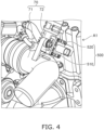
- Fig. 4 shows a part A1 of the engine 1 shown in Fig. 3 in an enlarged manner.
- the outlet portion 40, the blow-by gas mixing joint 70, and a heating device 500 of the blow-by gas treatment device 100 are provided outside the head cover 4 of the engine 1.
- the outlet portion 40 of the blow-by gas treatment device 100 protrudes outward from and is fixed to the upper surface portion 4A of the head cover 4.
- the heating device 500 is provided in the sub pipe 72 of the blow-by gas mixing joint 70.
- the heating device 500 has a heat storage portion 510 that is provided near a connection position connecting with the main pipe 71 in the sub pipe 72 and an electric heater 520 that is provided in the heat storage portion 510.
- the heat storage portion 510 plays a role of storing heat generated by the electric heater 520 and efficiently conducting the heat to the connection position between the sub pipe 72 and the main pipe 71.
- the heat storage portion 510 may be integrally provided with the blow-by gas mixing joint 70.
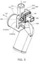
- Fig. 5 and Fig. 6 are perspective views showing a structural example of the blow-by gas mixing joint and the heating device of the present embodiment.
- Fig. 5 shows a perspective view seen from a side of the heating device 500
- Fig. 6 shows a perspective view seen from a side opposite to the heating device 500.
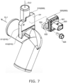
- Fig. 7 is an exploded perspective view showing the structural example of the blow-by gas mixing joint and the heating device of the present embodiment.
- An axial direction CL1 of the main pipe 71 of the blow-by gas mixing joint 70 is orthogonal to an axial direction CL2 of the sub pipe 72.
- the heat storage portion 510 of the heating device 500 has a first part 511 that is in contact with the outer surface of the sub pipe 72 and a second part 512 that extends from the first part 511 up to the outer surface of the main pipe 71.
- the first part 511 as the heat storage portion 510 may be provided to be in contact with at least half of the circumference of the outer surface of the sub pipe 72 when seen in the extension direction (axial direction CL2) of the sub pipe 72.
- the second part 512 that extends from the first part 511 may be provided to be in contact with at least half of the circumference of the outer surface of the main pipe 71 when seen in the extension direction (axial direction CL1) of the main pipe 71. That is, the heat storage portion 510 is provided to be wrapped by halves of the circumferences of the outer surfaces of the main pipe 71 and the sub pipe 72, respectively, at the connection position between the main pipe 71 and the sub pipe 72 of the blow-by gas mixing joint 70.
- a flat first surface FP is provided in the first part 511 of the heat storage portion 510, and the electric heater 520 is installed on this first surface FP.
- the electric heater 520 has a chassis 521 where a heating element is accommodated, an installation piece 522 that extends from the chassis 521, and a connector connection portion 523 for connecting a connector that supplies power (not shown) to the heating element.
- the electric heater 520 is fastened to the first surface FP by, for example, passing a bolt 525 through a hole 524 provided in the installation piece 522. This makes the electric heater 520 surface-connected to the flat first surface FP of the first part 511, whereby it is possible to stably fix the electric heater 520 and to efficiently conduct heat generated by the electric heater 520 to the first part 511.
- the electric heater 520 preferably has a positive temperature coefficient (PTC) heater.
- the PTC heater has positive temperature characteristics, and a self-control of the temperature is thus performed. This eliminates a need to provide a separate control portion for the electric heater 520 and makes it possible to simplify the device configuration.
- the PTC heater is accommodated in the chassis 521 and receives power through the connector (not shown) connected to the connector connection portion 523.
- the use of the electric heater 520 makes it possible to perform immediate heating by conducting electricity even when the engine is in a low-temperature state and rapidly suppresses freezing or condensation in the blow-by gas mixing joint 70.
- Fig. 8 is a cross-sectional view showing a structural example of the blow-by gas mixing joint of the present embodiment.
- Fig. 8 shows a cross-sectional view of the blow-by gas mixing joint cut in the extension direction at the central position of the sub pipe 72.
- the heat storage portion 510 is provided to project toward both sides from the sub pipe 72 at near the connecting part of the sub pipe 72 with the main pipe 71 in the blow-by gas mixing joint 70 and extends up to the main pipe 71.
- a part toward the sub pipe 72 from a connection position JP between the sub pipe 72 and the main pipe 71 is the first part 511
- a part toward the main pipe 71 is the second part 512.
- the electric heater 520 is installed in such a heat storage portion 510, whereby it is possible to conduct and store the heat generated by the electric heater 520 to and in the heat storage portion 510 and to transmit the heat from the sub pipe 72 through the main pipe 71. That is, when the heat storage portion 510 is provided, the heat capacity increases, and it becomes easy to maintain an appropriate temperature at the time of heating the main pipe 71 or the sub pipe 72 compared with a case where the main pipe 71 or the sub pipe 72 is directly heated.
- the gas G separated from the blow-by gas BG with the separation portion 330 shown in Fig. 2 passes through the through hole 680 in the outlet installation portion 700, and the gas G that has passed through the through hole 680 is led to the pressure regulating valve 350.
- the pressure regulating valve 350 opens. In such a case, the gas G led to the pressure regulating valve 350 is led to the intake system of the engine 1 through the pipe 41.
- the blow-by gas mixing joint 70 of the blow-by gas treatment device 100 is provided to protrude outward on the upper surface portion 4A of the head cover 4 as shown in Fig. 3 .
- the blow-by gas BG and the gas G separated from the blow-by gas BG contain water vapor. Therefore, when the engine 1 is in a low-temperature state, the water vapor that is contained in the gas G is frozen or condensed in the blow-by gas mixing joint 70, whereby there is a concern that the sub pipe 72 may be blocked. In such a case, there is a concern that the pipe 41 from the outlet portion 40 of the blow-by gas treatment device through the intake system of the engine and a gas channel that reaches the blow-by gas mixing joint 70 may be blocked.
- the heat storage portion 510 has the first part 511 that is in contact with the outer surface of the sub pipe 72 and the second part 512 that extends from the first part 511 up to the outer surface of the main pipe 71 as shown in Fig. 5 and Fig. 6 , and it is thus possible to conduct heat that has been generated by the heating device 500 and stored in the heat storage portion 510 to the sub pipe 72 with the first part 511 and to the main pipe 71 with the second part 512. This makes it possible to efficiently heat the connecting part between the sub pipe 72 and the main pipe 71 in the blow-by gas mixing joint 70.
- the first part 511 as the heat storage portion 510 is in contact with at least half of the circumference of the outer surface of the sub pipe 72
- the second part 512 is in contact with at least half of the circumference of the outer surface of the main pipe 71, whereby it is possible to conduct heat from the heat storage portion 510 to a wide range in the connecting part between the sub pipe 72 and the main pipe 71.
- the configuration in which heat is stored in the heat storage portion 510 and the heat is conducted to the sub pipe 72 and the main pipe 71 and the configuration in which the PTC heater is included as the electric heater 520 make it possible to stably conduct heat at a temperature self-controlled with the PTC heater.
- Fig. 9 and Fig. 10 are perspective view showing a configurational example of a first different embodiment of the present invention.
- Fig. 9 shows a perspective view seen from a side of the heating device 500
- Fig. 10 shows a perspective view seen from a side opposite to the heating device 500.
- the first different embodiment of the present invention is a configuration in which a cooling water flow path 400 that leads cooling water of the engine 1 is further provided.
- the cooling water flow path 400 is provided on a side opposite to the heating device 500 on the sub pipe 72. That is, the heating device 500 is provided on one side of the outer surface of the sub pipe 72, and the cooling water flow path 400 is provided on the other side.
- the cooling water flow path 400 is, for example, a metal pipe having a circular cross-sectional shape for passing the cooling water through.
- the cooling water flow path 400 has an upstream side channel 461, a downstream side channel 462, and a heat exchange member 380.
- One end portion of the upstream side channel 461 of the cooling water flow path 400 is connected to an exhaust gas recirculation device 80 (refer to Fig. 3 ).
- the exhaust gas recirculation device 80 has an EGR cooler and an EGR valve and recirculates a part of exhaust that flows in the intake system of the engine 1 as an exhaust recirculation gas to the intake system of the engine 1.
- one end portion of the upstream side channel 461 is connected to a water jacket (not shown) provided in the EGR valve of the exhaust gas recirculation device 80, draws out a part of the cooling water that flows in the water jacket of the EGR valve, and leads the cooling water to the other end portion of the upstream side channel 461.
- the cooling water being used is, for example, a long life coolant (LLC) that cools the cylinder block 2 and the cylinder head 3, which are shown in Fig. 2 , and the like and reaches a temperature of approximately 70°C to 80°C when the warm-up operation of the engine 1 has been completed.
- LLC long life coolant
- the other end portion of the upstream side channel 461 is connected to one end portion of the heat exchange member 380.
- the heat exchange member 380 is, for example, a tubular metal member and is provided as a linear member.
- the heat exchange member 380 is provided to form a mechanically and thermally integral structure with the sub pipe 72 of the blow-by gas mixing joint 70.
- the heat of the cooling water that passes through the cooling water flow path 400 can be efficiently conducted to the gas G that passes through the sub pipe 72 of the blow-by gas mixing joint 70. This makes it possible to heat the blow-by gas mixing joint 70 from both sides with the heat of the cooling water that flow through the cooling water flow path 400 together with heat from the heating device 500 and makes it possible to more reliably prevent the freezing or condensation of the water vapor that is contained in the gas G at low temperatures.
- the engine 1 includes a suction-type cooling fan (one example of a fan) on the front portion side of the engine 1.
- the cooling fan When the engine 1 operates, the cooling fan generates a cooling air WD toward the back of the engine 1 to cool the engine 1. If the cooling air WD generated by the cooling fan cools the warmed cooling water that passes through the upstream side channel 461, it becomes difficult for the cooling water to warm the gas G that passes through the inside of the sub pipe 72 of the blow-by gas mixing joint 70 through the heat exchange member 380. Therefore, there is a concern that it may be impossible to reliably suppress the water vapor that is contained in the gas G being frozen or condensed in the blow-by gas mixing joint 70.
- the cooling water flow path 400 is disposed at a position at which the air that is generated by the cooling fan of the engine 1 is avoided to prevent the cooling water that passes through the cooling water flow path 400 from being cooled by the cooling air WD from the cooling fan.
- a disposition shape example of the upstream side channel 461 is devised as described below.
- the upstream side channel 461 is disposed at a position at which the cooling air WD that is generated by the cooling fan is avoided near a region from the outlet portion 40 through the heat exchange member 380.
- the upstream side channel 461 is disposed on the downstream side of the cooling air WD with respect to a different part (for example, the heating device 500) so that the cooling air WD from the cooling fan does not directly hit the upstream side channel 461.
- the cooling water is capable of efficiently warming the gas G that passes through the inside of the sub pipe 72 of the blow-by gas mixing joint 70 through the heat exchange member 380, and it is possible to more reliably suppress the water vapor that is contained in the gas G being frozen or condensed in the blow-by gas mixing joint 70.
- the heat exchange member 380 itself in the cooling water flow path 400 is disposed at a position at which the cooling air WD that is generated by the cooling fan is avoided near the sub pipe 72 of the blow-by gas mixing joint 70.
- the heat exchange member 380 is disposed on the back side of the sub pipe 72, that is, disposed on the downstream side of the cooling air WD with respect to the sub pipe 72. Therefore, the flow of the cooling air WD is blocked by the sub pipe 72. In addition, the cooling air WD directly hitting the heat exchange member 380 is prevented.
- Fig. 11 is a schematic cross-sectional view showing a configurational example of a second different embodiment of the present invention.
- the second different embodiment of the present invention is a configuration in which at least a part of a thickness gradual increase part 721 provided in the sub pipe 72 is used as the heat storage portion 510. That is, the sub pipe 72 has the gradual increase part 721 that gradually increases in thickness from a far position toward a close position to the connection position.
- the gradual increase part 721 may be a part in which the thickness of the sub pipe 72 increases in a tapered shape or a part in which the thickness of the sub pipe 72 increases stepwise.
- Fig. 11 shows an example where the thickness of the sub pipe 72 increases in a tapered shape.
- the heat storage portion 510 includes at least a part of this gradual increase part 721.
- the electric heater 520 is installed on the outside of the gradual increase part 721 of the sub pipe 72.
- the thickness gradual increase part 721 in the sub pipe 72 is used as the heat storage portion 510, it is possible to store heat from the electric heater 520 in the gradual increase part 721 and efficiently conduct the heat to the connection position between the sub pipe 72 and the main pipe 71.
- the gradual increase part 721 is a part in which the thickness gradually increases toward the inside of the tube in the sub pipe 72, there is only a small part being exposed to the outside of the heat storage portion 510, and the gradual increase part 721 is thus less likely to be affected by heat dissipation due to an external air. Therefore, it is possible to efficiently conduct the stored heat to the gas G that flows in the sub pipe 72.
Landscapes
- Engineering & Computer Science (AREA)
- Mechanical Engineering (AREA)
- General Engineering & Computer Science (AREA)
- Chemical & Material Sciences (AREA)
- Combustion & Propulsion (AREA)
- Lubrication Details And Ventilation Of Internal Combustion Engines (AREA)
Abstract
A blow-by gas treatment device is provided, which is capable of more reliably suppressing water vapor that is contained in a gas separated from a blow-by gas being frozen or condensed, and an engine including the blow-by gas treatment device. The blow-by gas treatment device includes a mixing joint 70 having a main pipe 71 into which a new intake is introduced and a sub pipe 72 that introduces a gas, obtained by separating the blow-by gas into an oil and the gas, into the main pipe 71, and a heating device 500 that is provided in the sub pipe 72 of the mixing joint 70, wherein the heating device 500 has a heat storage portion 510 that is provided near a connection position connecting with the main pipe 71 in the sub pipe 72 and an electric heater 520 that is provided in the heat storage portion 510.
Description
- The present invention relates to a blow-by gas treatment device that is mounted in an internal combustion engine, such as a diesel engine, and separates a blow-by gas into an oil and a gas to supply the gas to an intake system of the engine, and an engine provided with a blow-by gas treatment device.
- A blow-by gas treatment device that separates a blow-by gas that is generated in an engine into an oil and a gas, such as an unburned gas and supplies the gas separated from the blow-by gas to an intake system of the engine is provided in, for example, a head cover of a diesel engine. The gas separated from the blow-by gas is sent to a mixing joint through a pipe and mixed with a new intake in the mixing joint. After that, the gas and the new intake that have been mixed with each other are supplied to the intake system of the engine.
- This kind of mixing joint is provided not inside the head cover of the engine but provided in a state of being exposed to the outside of the engine. Incidentally, the gas separated from the blow-by gas contains water vapor. Therefore, when the engine is placed in a low-temperature state, the water vapor that is contained in the gas separated from the blow-by gas may be frozen or condensed in the mixing joint.
- In such a case, there is a concern that a gas channel from the mixing joint through the intake system of the engine may be blocked by frozen or condensed moisture. When the gas channel is blocked, the internal pressure of the engine increases, and there is a concern that, for example, an oil seal provided in a crankcase may be damaged or rolled up and oil leakage may occur. In addition, when the gas channel is blocked, the internal pressure of the engine increases, and there is a concern that an oil gauge may fall out from an oil gauge guide and oil leakage may occur. Furthermore, when the gas channel is blocked, the internal pressure of the engine increases, and there is a concern that a turbocharger may absorb oil from the inside of the head cover.
- In contrast,
PTL 1 discloses a gas reflux device equipped with a warming mechanism. The warming mechanism described inPTL 1 has a conduit that allows cooling water of an engine to pass therethrough, and is capable of warming a reflux passage portion where a blow-by gas passage is connected to an intake passage. The blow-by gas reflux device described inPTL 1 is capable of warming the reflux passage portion with the cooling water of the engine that passes through the warming mechanism even when cooled down in a state of being exposed to the outside in extreme cold, and is thus capable of suppressing moisture in a blow-by gas from being frozen. - PTL 1:
Japanese Patent Application Publication No. 2020-97910 - However, the warming mechanism of the blow-by gas reflux device described in
PTL 1 is in a state of being exposed to the outside on the engine. The cooling water that passes through the warming mechanism is directly exposed to a cooling air that is generated by a cooling fan of the engine. Therefore, the temperature of the cooling water lowers. - As described above, there is a room for improvement in terms of more reliably suppressing moisture in the blow-by gas from being frozen or condensed in the blow-by gas treatment device.
- The present invention has been made in consideration of the above-described circumstance, and an object of the present invention is to provide a blow-by gas treatment device capable of more reliably suppressing water vapor that is contained in a gas separated from a blow-by gas from being frozen or condensed, and an engine including the blow-by gas treatment device. Solution to Problem
- A first aspect of the present invention is a blow-by gas treatment device treating a blow-by gas that is generated in an engine, the device including a mixing joint having a main pipe into which a new intake is introduced and a sub pipe that introduces a gas, obtained by separating the blow-by gas into an oil and the gas, into the main pipe, and a heating device that is provided in the sub pipe of the mixing joint, wherein the heating device has a heat storage portion that is provided near a connection position connecting with the main pipe in the sub pipe and an electric heater that is provided in the heat storage portion.
- According to the first aspect of the present invention, since the heat storage portion is provided near the connection position connecting with the main pipe in the sub pipe, it is possible to store heat generated by the electric heater in the heat storage portion and to efficiently conduct the heat from the heat storage portion to the connection position between the sub pipe and the main pipe. This heat makes it possible to more reliably suppress water vapor that is contained in a gas in the mixing joint being frozen or condensed.
- A second aspect of the present invention is the blow-by gas treatment device according to the first aspect of the present invention, wherein the sub pipe has a gradual increase part that gradually increases in thickness thereof from a far position toward a close position relative to the connection position, and the heat storage portion includes at least a part of the gradual increase part.
- According to the second aspect of the present invention, since at least a part of the thickness gradual increase part in the sub pipe is used as the heat storage portion, it is possible to store heat from the electric heater in the gradual increase part and efficiently conduct the heat to the connection position between the sub pipe and the main pipe.
- A third aspect of the present invention is the blow-by gas treatment device according to the first or second aspect of the present invention, wherein the heat storage portion has a first part that is in contact with an outer surface of the sub pipe and a second part that extends from the first part up to an outer surface of the main pipe.
- According to the third aspect of the present invention, since the heat storage part is provided from the part in contact with the outer surface of the sub pipe (first part) up to the outer surface of the main pipe (second part), it is possible to conduct the stored heat to the sub pipe by the first part and conduct the stored heat to the main pipe by the second part.
- A fourth aspect of the present invention is the blow-by gas treatment device according to the third aspect of the present invention, wherein the second part is in contact with at least half of a circumference of the outer surface of the main pipe in an extension direction of the main pipe.
- According to the fourth aspect of the present invention, since the second part is provided to be in contact with at least half of the circumference of the outer surface of the main pipe, it is possible to efficiently conduct the heat generated by the electric heater from the second part to the main pipe.
- A fifth aspect of the present invention is the blow-by gas treatment device according to the third aspect of the present invention, wherein the first part has a flat first surface, and the electric heater is installed on the first surface.
- According to the fifth aspect of the present invention, the electric heater is surface-connected to the flat first surface of the first part, whereby it is possible to efficiently conduct the heat generated by the electric heater to the first part.
- A sixth aspect of the present invention is the blow-by gas treatment device according to the third aspect of the present invention, wherein the first part and the second part are integrally provided with the mixing joint.
- According to the sixth aspect of the present invention, since the first part and the second part are integrally provided with the mixing joint, there is no need to connect a heat storage part to the mixing joint as a separate body, and it is possible to simplify manufacturing steps.
- A seventh aspect of the present invention is the blow-by gas treatment device according to any one of the first to sixth aspects of the present invention, wherein the heat storage portion is in contact with at least half of a circumference of the outer surface of the sub pipe in an extension direction of the sub pipe.
- According to the seventh aspect of the present invention, since the heat storage portion is provided to be in contact with at least half of the circumference of the outer surface of the sub pipe, it is possible to efficiently conduct the heat generated by the electric heater from the heat storage portion to the sub pipe.
- An eighth aspect of the present invention is the blow-by gas treatment device according to any one of the first to seventh aspects of the present invention, the device further including a cooling water flow path through which cooling water of the engine is led and heat is conducted to the gas that flows through the sub pipe.
- According to the eighth aspect of the present invention, the cooling water that passes through the cooling water flow path efficiently conducts heat to the gas that has been separated from the blow-by gas and passes through the sub pipe of the mixing joint, and the mixing joint is heated from both sides with the heat together with heat from the heating device, whereby it is possible to more reliably suppress the water vapor that is contained in the gas in the mixing joint being frozen or condensed.
- A ninth aspect of the present invention is the blow-by gas treatment device according to the eighth aspect of the present invention, wherein the cooling water flow path is disposed at a position where a wind that is generated by a fan of the engine is avoided.
- According to the ninth aspect of the present invention, the temperature of the cooling water that passes through the cooling water flow path being lowered by the wind that is generated by the fan of the engine is suppressed. Therefore, the cooling water that passes through the cooling water flow path efficiently conducts heat to the gas that has been separated from the blow-by gas and passes through the sub pipe of the mixing joint through a heat exchange member, and it is possible to more reliably suppress the water vapor that is contained in the gas in the mixing joint being frozen or condensed.
- A tenth aspect of the present invention is the blow-by gas treatment device according to any one of the first to ninth aspects of the present invention, wherein the electric heater has a positive temperature coefficient (PTC) heater.
- According to the tenth aspect of the present invention, a self-control of the temperature is performed by the positive temperature characteristics of the PTC heater, there is no need to provide a separate control portion for the electric heater, and it is possible to simplify the device configuration.
- An eleventh aspect of the present invention is an engine including a blow-by gas treatment device treating a blow-by gas that is generated in the engine, wherein the blow-by gas treatment device includes a mixing joint having a main pipe into which a new intake is introduced and a sub pipe that introduces a gas, obtained by separating the blow-by gas into an oil and the gas, into the main pipe, and a heating device that is provided in the sub pipe of the mixing joint, and wherein the heating device has a heat storage portion that is provided near a connection position connecting with the main pipe in the sub pipe and an electric heater that is provided in the heat storage portion.
- According to the eleventh aspect of the present invention, since the heat storage portion is provided near the connection position connecting with the main pipe in the sub pipe, it is possible to store heat generated by the electric heater in the heat storage portion and to efficiently conduct the heat from the heat storage portion to the connection portion between the sub pipe and the main pipe. This heat makes it possible to more reliably suppress water vapor that is contained in a gas in the mixing joint being frozen or condensed.
- According to the present invention, it is possible to provide a blow-by gas treatment device capable of more reliably suppressing water vapor that is contained in a gas separated from a blow-by gas being frozen or condensed and an engine including the blow-by gas treatment device.
-
- [
Fig. 1 ]
Fig. 1 is a cross-sectional view showing an engine including a blow-by gas treatment device according to an embodiment of the present invention. - [
Fig. 2 ]
Fig. 2 is a cross-sectional view showing a structural example of the blow-by gas treatment device according to the present embodiment in an X-Z plane. - [
Fig. 3] Fig. 3 is a perspective view of the engine including the blow-by gas treatment device according to the present embodiment seen from diagonally above. - [
Fig. 4] Fig. 4 is a perspective view of the engine including the blow-by gas treatment device according to the present embodiment seen from diagonally above. - [
Fig. 5] Fig. 5 is a perspective view showing a structural example of a blow-by gas mixing joint and a heating device of the present embodiment. - [
Fig. 6 ]
Fig. 6 is a perspective view showing a structural example of the blow-by gas mixing joint and the heating device of the present embodiment. - [
Fig. 7 ]
Fig. 7 is a perspective view showing a structural example of the blow-by gas mixing joint and the heating device of the present embodiment. - [
Fig. 8 ]
Fig. 8 is a cross-sectional view showing a structural example of the blow-by gas mixing joint of the present embodiment. - [
Fig. 9 ]
Fig. 9 is a perspective view showing a configurational example of a first different embodiment of the present invention. - [
Fig. 10 ]
Fig. 10 is a perspective view showing a configurational example of the first different embodiment of the present invention. - [
Fig. 11 ]
Fig. 11 is a schematic cross-sectional view showing a configurational example of a second different embodiment of the present invention. - Hereinafter, embodiments of the present invention will be described with reference to the drawings.
- The embodiments to be described below are specific suitable examples of the present invention, and a variety of technically preferable limitations are thus attached thereto. However, the scope of the present invention is not limited to these aspects unless the present invention is described to be particularly limited in the following description. In addition, in each of the drawings, the same components will be given the same reference sign and will not be described in detail as appropriate.
-
Fig. 1 is a cross-sectional view showing an engine including a blow-by gas treatment device according to an embodiment of the present invention. - An
engine 1 shown inFig. 1 is an internal combustion engine and is, for example, an industrial diesel engine. Theengine 1 is, for example, a multi-cylinder engine such as a turbocharger-attached supercharged high-output three-cylinder engine or four-cylinder engine. Theengine 1 is mounted in, for example, industrial machinery such as construction machinery or agricultural machinery. In addition, theengine 1 may configure a hybrid drive device by combining a charging power supply battery for driving and an electric motor for driving. - The
engine 1 includes acylinder block 2, acylinder head 3, ahead cover 4, anoil pan 7, and a blow-bygas treatment device 100. Thecylinder head 3 is assembled on thecylinder block 2. Thehead cover 4 is assembled on thecylinder head 3. Thecylinder block 2 has acylinder 5 in the upper portion and acrankcase 6 in the lower portion. Theoil pan 7 is disposed in the lower portion of thecrankcase 6. Apiston 8 is disposed in thecylinder 5. Acrankshaft 9 is disposed to penetrate thecrankcase 6. Thepiston 8 is coupled with thecrankshaft 9 through a connectingrod 10. - As shown in
Fig. 1 , thecylinder 5 has a valvetrain cam chamber 11. A valvetrain cam shaft 12 is accommodated in the valvetrain cam chamber 11. Atappet 13 is vertically movable along atappet guide hole 14. The lower portion of thetappet 13 is on the valvetrain cam shaft 12. Apush rod 15 passes through aninsertion hole 16. Arocker arm 17 is disposed in thehead cover 4. The upper end portion of thepush rod 15 abuts on therocker arm 17. - The
rocker arm 17 is biased toward the upper end portion of thepush rod 15 by aspring 18. Anintake valve 19 and anexhaust valve 20 vertically move by power conducted by the rotation of the valvetrain cam shaft 12 through thepush rod 15 and therocker arm 17 and open and close an intake port and an exhaust port, respectively. - As shown in
Fig. 1 , for example, anoil outflow hole 21 is provided in thetappet 13. Anoil drop hole 22 is provided from the valvetrain cam chamber 11 through thecrankcase 6. Therefore, theinsertion hole 16, the inside of thetappet 13, theoil outflow hole 21, the valvetrain cam chamber 11, and theoil drop hole 22 configure anoil return channel 99. Theoil return channel 99 is capable of returning an oil in thehead cover 4 to theoil pan 7 through the inside of thecrankcase 6. Each cylinder in thecylinder head 3 is connected to anintake passage 30 and anexhaust passage 31. - As shown in
Fig. 1 , there are cases where a blow-by gas BG is generated in any of a compression stroke and a combustion stroke of theengine 1. The blow-by gas BG is a gas that flows into thecrankcase 6 through a gap between thepiston 8 and thecylinder 5 shown inFig. 1 and contains a mist of an unburned fuel component, a combusted gas component, an oil, or the like. The blow-by gas BG that has leaked into thecrankcase 6 from the gap between thecylinder 5 and thepiston 8 rises in thehead cover 4 through, for example, the above-describedoil return channel 99. That is, when leaking into thecrankcase 6 from the gap between thecylinder 5 and thepiston 8, the blow-by gas BG intrudes into thehead cover 4 through, for example, theoil drop hole 22, the valvetrain cam chamber 11, theoil outflow hole 21 in thetappet 13, and theinsertion hole 16 in theoil return channel 99 as a blow-by gas passage channel. The above-describedoil return channel 99 is one example of the blow-by gas passage channel. The blow-by gas passage channel is not limited to the above-describedoil return channel 99 alone. - As shown in
Fig. 1 , the blow-bygas treatment device 100 is provided in thehead cover 4. The blow-bygas treatment device 100 plays a role of separating the blow-by gas BG into an oil OL (refer toFig. 2 ) and a gas (treated gas) G from which the mist of the oil OL has been separated (refer toFig. 2 ). For example, the gas G that is contained in the blow-by gas BG is sent to apipe 41 connected to an external intake system of thehead cover 4 through the blow-bygas treatment device 100. The gas G that is contained in the blow-by gas BG is, for example, an unburned gas component or combusted gas component from which the oil OL and the mist of the oil OL have been removed from the blow-by gas BG. The oil (lubricant component) OL is collected into theoil pan 7 through, for example, thehead cover 4, the inside of thecylinder head 3, and theoil return channel 99. - A connecting
tube 50T in anintake pipe 50 shown inFig. 1 and thepipe 41 are connected to each other through a blow-by gas mixing joint (one example of a mixing joint) 70. When a new intake AR is sucked into theintake pipe 50, the new intake AR passes through anair cleaner 52 and the connectingtube 50T and enters amain pipe 71 of the blow-by gas mixing joint 70. On the other hand, the gas G obtained by separating the oil OL from the blow-by gas BG with the blow-bygas treatment device 100 enters asub pipe 72 of the blow-by gas mixing joint 70 from anoutlet portion 40 of the blow-bygas treatment device 100 through thepipe 41. This makes the new intake AR and the gas G mixed together in the blow-by gas mixing joint 70 and turn into a sucked air B. - On the other hand, exhaust from the
exhaust passage 31 is supplied to aturbine 62 of aturbocharger 60 and thereby rotates theturbine 62 and acompressor 61 at a high speed. The mixed sucked air B is supplied to and compressed in thecompressor 61 of theturbocharger 60. A compressed sucked air C is supercharged into theintake passage 30 of the intake system. - Next, a structural example of the blow-by gas treatment device according to the present embodiment will be described with reference to drawings.
-
Fig. 2 is a cross-sectional view showing the structural example of the blow-by gas treatment device according to the present embodiment in an X-Z plane. - Here, an X direction shown in
Fig. 1 andFig. 2 is a front and back direction of theengine 1 shown inFig. 1 , that is, the width direction of thecrankshaft 9. An Y direction is the right and left direction of theengine 1. A Z direction is the up and down direction of theengine 1. The X, Y, and Z directions are orthogonal to one another. - As shown in
Fig. 1 andFig. 2 , the blow-bygas treatment device 100 is also referred to as a breather device or a breather and has amain structure portion 101, theoutlet portion 40, and the blow-by gas mixing joint 70. Themain structure portion 101 is disposed in thehead cover 4. Theoutlet portion 40 and the blow-by gas mixing joint 70 are provided to be exposed to the outside of thehead cover 4. Themain structure portion 101 is capable of separating the blow-by gas BG into the oil OL and the gas G and guiding the oil OL and the gas G with separate channels. - As shown in
Fig. 2 , themain structure portion 101 is provided in thehead cover 4. Theoutlet portion 40 is provided to protrude upward from thehead cover 4. Furthermore, theoutlet portion 40 is disposed at, for example, a substantially central position CP in the front and back direction, which is the X direction, of themain structure portion 101 as shown inFig. 2 . A detailed structural example of theoutlet portion 40 will be described after a detailed structural example of themain structure portion 101 is described. - First, the structural example of the
main structure portion 101 of the blow-bygas treatment device 100 will be described with reference toFig. 1 andFig. 2 . - As shown in
Fig. 1 andFig. 2 , themain structure portion 101 is accommodated in thehead cover 4. Specifically, thehead cover 4 has anupper surface portion 4A, afront surface portion 4B, aback surface portion 4C, and right and leftsurface portions 4D. Themain structure portion 101 is disposed in a space surrounded by theupper surface portion 4A, thefront surface portion 4B, theback surface portion 4C, and the right and leftsurface portions 4D. As shown inFig. 2 , themain structure portion 101 incorporates and guides the blow-by gas BG and separates the oil OL and the gas G that are contained in the blow-by gas BG from the blow-by gas BG. In addition, themain structure portion 101 guides the oil OL and the gas G with separate channels to prevent the oil OL and the gas G separated from the blow-by gas BG from leaking to the outside of theengine 1. In order for that, thehead cover 4 is held in thecylinder head 3 in a state where the inside of thehead cover 4 remains airtight with respect to the outside of thehead cover 4. This makes the blow-by gas BG and the oil OL and the gas G separated from the blow-by gas BG kept from leaking to the outside of theengine 1. - As shown in
Fig. 2 , themain structure portion 101 schematically has a first blow-bygas incorporation portion 111, a second blow-bygas incorporation portion 112, aseparation portion 330, a first oilguide groove portion 151, a second oilguide groove portion 152, afirst oil drain 161, and asecond oil drain 162. The first oilguide groove portion 151 and the second oilguide groove portion 152 are each one example of "oil guide portion." Thefirst oil drain 161 and thesecond oil drain 162 are each one example of "oil drain." - The
main structure portion 101 has apartition wall portion 200, aguide wall portion 203, and aguide plate 295 to configure the above-described components as shown inFig. 2 . Thepartition wall portion 200 is disposed in an X-Y plane, that is, horizontally, in thehead cover 4, and partitions alower portion region 4P andupper portion regions head cover 4. Therefore, thelower portion region 4P and theupper portion regions - As shown in
Fig. 2 , theguide wall portion 203 reliably guides only the treated gas G, that is, the gas G obtained by separating the mist of the oil OL from the blow-by gas BG, to theoutlet portion 40. Theguide wall portion 203 is disposed between thepartition wall portion 200 and theupper surface portion 4A of thehead cover 4 and partitions theupper portion region 4Q and theupper portion region 4R. Theupper portion region 4Q and theupper portion region 4R are independent spaces from each other. - Next, the first blow-by
gas incorporation portion 111 and the second blow-bygas incorporation portion 112 will be described with reference toFig. 2 . - The first blow-by
gas incorporation portion 111 and the second blow-bygas incorporation portion 112 are holes formed by thepartition wall portion 200 and theguide plate 295 and incorporate the blow-by gas BG. Thepartition wall portion 200 is divided into a first guidelower surface portion 231 side and a second guidelower surface portion 232 side across theseparation portion 330 as the center. The first blow-bygas incorporation portion 111 is provided at a position closer to thefront surface portion 4B (that is, on the front side of the engine 1) and incorporates the blow-by gas BG from the front side. In addition, the second blow-bygas incorporation portion 112 is provided at a position closer to theback surface portion 4C (that is, on the back side of the engine 1) and incorporates the blow-by gas BG from the back side. - The
guide plate 295 shown inFig. 2 has a portion separated from thepartition wall portion 200 to face the first guidelower surface portion 231 and the second guidelower surface portion 232 and is disposed along the X-Y plane. - As shown in
Fig. 1 , when the blow-by gas BG that has risen in thecrankcase 6 reaches thelower portion region 4P of thehead cover 4 shown inFig. 2 , the blow-by gas BG passes through the first blow-bygas incorporation portion 111, is incorporated between the first guidelower surface portion 231 of thepartition wall portion 200 and theguide plate 295, and is guided toward theseparation portion 330. Alternatively, the blow-by gas BG passes through the second blow-bygas incorporation portion 112, is incorporated between the second guidelower surface portion 232 and theguide plate 295, and is guided toward theseparation portion 330. In addition, the blow-by gas BG reaches animpactor 120 of theseparation portion 330 that is present at a central position RP in the X direction, which is the front and back direction, like arrows shown inFig. 2 . - Next, the
separation portion 330 will be described with reference toFig. 2 . - The
separation portion 330 shown inFig. 2 is also referred to as an impactor-type separator, has theimpactor 120, afilter 130, and acollision plate 133, and is provided between the first blow-bygas incorporation portion 111 and the second blow-bygas incorporation portion 112 in the front and back direction of theengine 1. More specifically, theseparation portion 330 is provided at the central portion between thefirst oil drain 161 and thesecond oil drain 162 in the front and back direction of theengine 1, that is, at the central position RP. - The
impactor 120 has a function of a nozzle or an orifice. The axial direction of adiaphragm hole 121 in theimpactor 120 is along the vertical direction or the up and down direction, which is the Z direction, that is, a vertical diaphragm hole. Theimpactor 120 is a flow rate increase operation portion capable of increasing the flow rate of the blow-by gas BG by passing the blow-by gas BG upward along thediaphragm hole 121. Theimpactor 120 is disposed at the central position RP in the X direction of thepartition wall portion 200. This makes the blow-by gas BG that is incorporated by the first blow-bygas incorporation portion 111 and the blow-by gas BG that is incorporated by the second blow-bygas incorporation portion 112 equally guided to theimpactor 120. Theimpactor 120 increases the flow rate of the blow-by gas BG that flows through thediaphragm hole 121 and then leads the blow-by gas BG to thefilter 130. - As shown in
Fig. 2 , thefilter 130 is replaceably installed on thepartition wall portion 200. Thefilter 130 is a member for improving the performance of separating the oil OL from the blow-by gas BG (that is, the oil OL separation performance) and is made of a material, for example, glass wool or steel wool. However, the material of thefilter 130 is not particularly limited. Thefilter 130 is disposed between thecollision plate 133 and theimpactor 120. That is, thefilter 130 has theimpactor 120 as the flow rate increase operation portion disposed on the lower surface thereof. Thefilter 130 has thecollision plate 133 disposed on the upper surface thereof. - The
collision plate 133 is, for example, a metal plate and extends in the horizontal direction. Thecollision plate 133 separates the blow-by gas BG into the oil OL and the gas G that does not contain the mist of the oil OL by causing the blow-by gas BG to collide with thecollision plate 133 at an increased flow rate through thefilter 130. The blow-by gas BG that flows at an increased flow rate is caused to collide with thecollision plate 133 while a foreign matter is removed through thefilter 130 and is thereby separated into the oil OL and the gas G that does not contain the mist of the oil OL. In addition, the gas G separated from the blow-by gas BG with theseparation portion 330 is discharged from thefilter 130. - As described above, the
guide wall portion 203 is provided between thepartition wall portion 200 and theupper surface portion 4A of thehead cover 4. Therefore, the gas G that does not contain the mist of the oil OL discharged from thefilter 130 is guided with theguide wall portion 203, passes through apassage 135 in theupper portion region 4Q, and is led to theoutlet portion 40. Theguide wall portion 203 is disposed in thehead cover 4 and is thereby capable of guiding the gas G separated with theseparation portion 330 to theoutlet portion 40. - On the other hand, the oil OL separated from the blow-by gas BG with the
separation portion 330 passes through thefilter 130, falls down, and drops on the upper surface of theimpactor 120. The oil OL that has dropped on the upper surface of theimpactor 120 flows along the upper surface of theimpactor 120 and flows toward the first oilguide groove portion 151 and the second oilguide groove portion 152. - The
separation portion 330 is positioned at the central position RP in the X direction shown inFig. 2 and plays a role of a gathering portion capable of gathering the blow-by gas BG toward the central portion in the X direction from the front side and the back side of theengine 1. Theseparation portion 330 is present at the central position RP in the X direction of thehead cover 4 as described above and is thus capable of gathering the blow-by gas BG to the central portion from the front side and the back side in the X direction in thehead cover 4 and separating the blow-by gas BG into the oil OL and the gas G that does not contain the mist of the oil OL. - Next, the first oil
guide groove portion 151 and the second oilguide groove portion 152 will be described with reference toFig. 2 . - The first oil
guide groove portion 151 shown inFig. 2 exhibits a groove shape, is provided from thefront surface portion 4B of thehead cover 4 up to the vicinity of thefilter 130 and is inclined downward from thefilter 130 toward thefront surface portion 4B of thehead cover 4. Similarly, the second oilguide groove portion 152 exhibits a groove shape, is provided from theback surface portion 4C of thehead cover 4 up to the vicinity of thefilter 130 and is inclined downward from thefilter 130 toward theback surface portion 4C of thehead cover 4. The first oilguide groove portion 151 and the second oilguide groove portion 152 guide the oil OL separated from the blow-by gas BG with theseparation portion 330. The first oilguide groove portion 151 is a specific structural example of "first oil guide portion" and is capable of guiding the oil OL that is discharged from thefilter 130 forward in an X1 direction when theengine 1 ofFig. 1 is inclined forward and leading the oil OL to thefirst oil drain 161 on the front side. Similarly, the second oilguide groove portion 152 is a specific structural example of "second oil guide portion" and is capable of guiding the oil OL that is discharged from thefilter 130 backward in an X2 direction when theengine 1 ofFig. 1 is inclined backward and leading the oil OL to thesecond oil drain 162 on the back side. - The first oil
guide groove portion 151 and the second oilguide groove portion 152 may be connected to each other. In this case, in one oil guide groove portion, a part provided toward the front side of theengine 1 from thefilter 130 is referred to as the first oilguide groove portion 151, and a part provided toward the back side of theengine 1 from thefilter 130 is referred to as the second oilguide groove portion 152. - Next, the
first oil drain 161 and thesecond oil drain 162 will be described with reference toFig. 2 . - The
first oil drain 161 is provided on the front side of theengine 1 and exhibits, for example, a tubular shape. Thefirst oil drain 161 is provided downward, which is a Z1 direction, in thehead cover 4 at a front position of the first guidelower surface portion 231 of thepartition wall portion 200. Thefirst oil drain 161 has a check valve, temporarily stores the oil OL guided by the first oilguide groove portion 151, and discharges the oil OL into theengine 1. Similarly, thesecond oil drain 162 is provided on the back side of theengine 1 and exhibits, for example, a tubular shape. Thesecond oil drain 162 is provided downward, which is the Z1 direction, in thehead cover 4 at a back position of the second guidelower surface portion 232 of thepartition wall portion 200. Thesecond oil drain 162 has a check valve, temporarily stores the oil OL guided by the second oilguide groove portion 152, and discharges the oil OL into theengine 1. - Therefore, when the
engine 1 is inclined forward, the oil OL separated from the blow-by gas BG with theseparation portion 330 is guided in the X1 direction by the first oilguide groove portion 151, temporarily stored in thefirst oil drain 161, and discharged in the Z1 direction through thefirst oil drain 161. Similarly, when theengine 1 is inclined backward, the oil OL separated from the blow-by gas BG with theseparation portion 330 is guided in the X2 direction by the second oilguide groove portion 152, temporarily stored in thesecond oil drain 162, and discharged in the Z1 direction through thesecond oil drain 162. In thehead cover 4, the oil OL discharged from thefirst oil drain 161 and thesecond oil drain 162 is collected into theoil pan 7 from, for example, thehead cover 4 shown inFig. 1 through the above-describedoil return channel 99. Alternatively, it is also possible to collect the discharged oil OL into, for example, an oil container, not shown. This makes the oil OL that is discharged from thefirst oil drain 161 and thesecond oil drain 162 discharged into theengine 1 and prevents the oil OL from leaking to the outside of theengine 1. - Next, a structural example of the
outlet portion 40 of the blow-bygas treatment device 100 will be described with reference toFig. 2 - As described already, the
outlet portion 40 shown inFig. 2 is provided to protrude in the Z direction from thehead cover 4. Specifically, theoutlet portion 40 is provided to protrude outward from theupper surface portion 4A of thehead cover 4. Theoutlet portion 40 is disposed at, for example, the substantially central position CP in the front and back direction, which is the X direction, of themain structure portion 101 of thehead cover 4. - The
outlet portion 40 has a pressure regulating valve (diaphragm) 350 and acontainer body 750 as shown inFig. 2 and adjusts the pressure of the gas G at, for example, the substantially central position CP of theengine 1 to send only the gas G led from themain structure portion 101 to thepipe 41 of the intake system of theengine 1. That is, theoutlet portion 40 is capable of returning the gas G separated from the blow-by gas BG with theseparation portion 330 to the intake system of theengine 1 through thepipe 41 and combusting the gas G again. This makes it possible to improve the environmental performance of theengine 1 by preventing the gas G separated from the blow-by gas BG from being discharged to the outside of theengine 1. - The
pressure regulating valve 350 suppresses the inflow of the new intake AR into theengine 1 through the blow-by gas mixing joint 70 and thepipe 41 of the intake system while adjusting the pressure between the inside of theengine 1 and the intake system of the engine 1 (refer toFig. 1 ). - As shown in
Fig. 2 , thecontainer body 750 is indirectly fixed to theupper surface portion 4A of thehead cover 4 through anoutlet installation portion 700 and holds thepressure regulating valve 350. Thecontainer body 750 may be directly fixed to theupper surface portion 4A of thehead cover 4 without theoutlet installation portion 700. Alternatively, theoutlet installation portion 700 may be a part of thehead cover 4 or is formed around a through hole forgas discharge 680 provided in thehead cover 4 to rise toward the outside from theupper surface portion 4A of thehead cover 4. - The through hole for
gas discharge 680 is provided in a circular shape to penetrate theupper surface portion 4A of thehead cover 4 along the Z direction. That is, the central axis of the through hole forgas discharge 680 is along the Z direction. The throughhole 680 allows the gas G separated from the blow-by gas BG with theseparation portion 330 to pass through. - The
container body 750 is also referred to as a spacer or the like and is installed on theoutlet installation portion 700. Thecontainer body 750 is capable of temporarily storing the gas G that comes up from the inside of thehead cover 4 through the throughhole 680 of theoutlet installation portion 700 and supplying the gas G to the intake system side of theengine 1 shown inFig. 1 through thepipe 41. Thecontainer body 750 has agas flow path 42. Thegas flow path 42 passes through the throughhole 680 and leads the gas G that has further passed through thepressure regulating valve 350 to the intake system of theengine 1 through thepipe 41. - Next, a structural example of the
engine 1 and the blow-bygas treatment device 100 according to the present embodiment will be described in detail with reference toFig. 3 . -
Fig. 3 andFig. 4 are perspective views of the engine including the blow-by gas treatment device according to the present embodiment seen from diagonally above. -
Fig. 4 shows a part A1 of theengine 1 shown inFig. 3 in an enlarged manner. - As shown in
Fig. 3 andFig. 4 , theoutlet portion 40, the blow-by gas mixing joint 70, and aheating device 500 of the blow-bygas treatment device 100 are provided outside thehead cover 4 of theengine 1. Theoutlet portion 40 of the blow-bygas treatment device 100 protrudes outward from and is fixed to theupper surface portion 4A of thehead cover 4. - As shown in
Fig. 3 andFig. 4 , theheating device 500 is provided in thesub pipe 72 of the blow-by gas mixing joint 70. Theheating device 500 has aheat storage portion 510 that is provided near a connection position connecting with themain pipe 71 in thesub pipe 72 and anelectric heater 520 that is provided in theheat storage portion 510. Theheat storage portion 510 plays a role of storing heat generated by theelectric heater 520 and efficiently conducting the heat to the connection position between thesub pipe 72 and themain pipe 71. Theheat storage portion 510 may be integrally provided with the blow-by gas mixing joint 70. Therefore, there is no need to connect theheat storage portion 510 to the blow-by gas mixing joint 70 as a separate body, and theheat storage portion 510 and the blow-by gas mixing joint 70 are formed of the same material, which makes it possible to continuously transmit heat from theheat storage portion 510 up to the blow-by gas mixing joint 70. -
Fig. 5 andFig. 6 are perspective views showing a structural example of the blow-by gas mixing joint and the heating device of the present embodiment.Fig. 5 shows a perspective view seen from a side of theheating device 500, andFig. 6 shows a perspective view seen from a side opposite to theheating device 500. -
Fig. 7 is an exploded perspective view showing the structural example of the blow-by gas mixing joint and the heating device of the present embodiment. - An axial direction CL1 of the
main pipe 71 of the blow-by gas mixing joint 70 is orthogonal to an axial direction CL2 of thesub pipe 72. Theheat storage portion 510 of theheating device 500 has afirst part 511 that is in contact with the outer surface of thesub pipe 72 and asecond part 512 that extends from thefirst part 511 up to the outer surface of themain pipe 71. Thefirst part 511 as theheat storage portion 510 may be provided to be in contact with at least half of the circumference of the outer surface of thesub pipe 72 when seen in the extension direction (axial direction CL2) of thesub pipe 72. In addition, thesecond part 512 that extends from thefirst part 511 may be provided to be in contact with at least half of the circumference of the outer surface of themain pipe 71 when seen in the extension direction (axial direction CL1) of themain pipe 71. That is, theheat storage portion 510 is provided to be wrapped by halves of the circumferences of the outer surfaces of themain pipe 71 and thesub pipe 72, respectively, at the connection position between themain pipe 71 and thesub pipe 72 of the blow-by gas mixing joint 70. - In addition, as shown in
Fig. 7 , a flat first surface FP is provided in thefirst part 511 of theheat storage portion 510, and theelectric heater 520 is installed on this first surface FP. Theelectric heater 520 has achassis 521 where a heating element is accommodated, aninstallation piece 522 that extends from thechassis 521, and aconnector connection portion 523 for connecting a connector that supplies power (not shown) to the heating element. Theelectric heater 520 is fastened to the first surface FP by, for example, passing abolt 525 through ahole 524 provided in theinstallation piece 522. This makes theelectric heater 520 surface-connected to the flat first surface FP of thefirst part 511, whereby it is possible to stably fix theelectric heater 520 and to efficiently conduct heat generated by theelectric heater 520 to thefirst part 511. - The
electric heater 520 preferably has a positive temperature coefficient (PTC) heater. The PTC heater has positive temperature characteristics, and a self-control of the temperature is thus performed. This eliminates a need to provide a separate control portion for theelectric heater 520 and makes it possible to simplify the device configuration. The PTC heater is accommodated in thechassis 521 and receives power through the connector (not shown) connected to theconnector connection portion 523. The use of theelectric heater 520 makes it possible to perform immediate heating by conducting electricity even when the engine is in a low-temperature state and rapidly suppresses freezing or condensation in the blow-by gas mixing joint 70. -
Fig. 8 is a cross-sectional view showing a structural example of the blow-by gas mixing joint of the present embodiment.Fig. 8 shows a cross-sectional view of the blow-by gas mixing joint cut in the extension direction at the central position of thesub pipe 72. Theheat storage portion 510 is provided to project toward both sides from thesub pipe 72 at near the connecting part of thesub pipe 72 with themain pipe 71 in the blow-by gas mixing joint 70 and extends up to themain pipe 71. In theheat storage portion 510, a part toward thesub pipe 72 from a connection position JP between thesub pipe 72 and themain pipe 71 is thefirst part 511, and a part toward themain pipe 71 is thesecond part 512. - The
electric heater 520 is installed in such aheat storage portion 510, whereby it is possible to conduct and store the heat generated by theelectric heater 520 to and in theheat storage portion 510 and to transmit the heat from thesub pipe 72 through themain pipe 71. That is, when theheat storage portion 510 is provided, the heat capacity increases, and it becomes easy to maintain an appropriate temperature at the time of heating themain pipe 71 or thesub pipe 72 compared with a case where themain pipe 71 or thesub pipe 72 is directly heated. - Next, a freezing or condensation prevention treatment of the gas G that flows in the
sub pipe 72 of the blow-by gas mixing joint 70 will be described. - First, the flow of the gas G separated from the blow-by gas BG with the
separation portion 330 shown inFig. 2 will be described. The gas G separated from the blow-by gas BG with theseparation portion 330 shown inFig. 2 passes through the throughhole 680 in theoutlet installation portion 700, and the gas G that has passed through the throughhole 680 is led to thepressure regulating valve 350. In addition, when the pressure in theengine 1 increases to a predetermined pressure or higher or the pressure of the intake system of theengine 1 decreases to lower than a predetermined pressure, thepressure regulating valve 350 opens. In such a case, the gas G led to thepressure regulating valve 350 is led to the intake system of theengine 1 through thepipe 41. - Here, the blow-by
gas mixing joint 70 of the blow-bygas treatment device 100 is provided to protrude outward on theupper surface portion 4A of thehead cover 4 as shown inFig. 3 . Incidentally, the blow-by gas BG and the gas G separated from the blow-by gas BG contain water vapor. Therefore, when theengine 1 is in a low-temperature state, the water vapor that is contained in the gas G is frozen or condensed in the blow-by gas mixing joint 70, whereby there is a concern that thesub pipe 72 may be blocked. In such a case, there is a concern that thepipe 41 from theoutlet portion 40 of the blow-by gas treatment device through the intake system of the engine and a gas channel that reaches the blow-by gas mixing joint 70 may be blocked. When the gas channel is blocked, the internal pressure of the engine increases, and there is a concern that, for example, an oil seal provided in a crankcase may be damaged or rolled up and oil leakage may occur. In addition, when the gas channel is blocked, the internal pressure of the engine increases, and there is a concern that an oil gauge may fall out from an oil gauge guide and oil leakage may occur. Furthermore, when the gas channel is blocked, the internal pressure of the engine increases, and there is a concern that a turbocharger may absorb oil from the inside of the head cover. - In order to prevent such blocking of the gas channel, in the blow-by
gas treatment device 100 according to the present embodiment and theengine 1 including the blow-bygas treatment device 100, an effort shown inFig. 3 has been implemented. That is, heat is generated by theelectric heater 520 in theheating device 500, and this heat is stored in theheat storage portion 510 and transmitted to thesub pipe 72 and themain pipe 71. When electricity is conducted to theelectric heater 520 at the time of starting theengine 1, it is possible to increase the temperature of the gas G that flows in thesub pipe 72 even before the warm-up operation of theengine 1 is completed by conducting heat to the gas G that flows in thesub pipe 72. - The
heat storage portion 510 has thefirst part 511 that is in contact with the outer surface of thesub pipe 72 and thesecond part 512 that extends from thefirst part 511 up to the outer surface of themain pipe 71 as shown inFig. 5 andFig. 6 , and it is thus possible to conduct heat that has been generated by theheating device 500 and stored in theheat storage portion 510 to thesub pipe 72 with thefirst part 511 and to themain pipe 71 with thesecond part 512. This makes it possible to efficiently heat the connecting part between thesub pipe 72 and themain pipe 71 in the blow-by gas mixing joint 70. - Furthermore, the
first part 511 as theheat storage portion 510 is in contact with at least half of the circumference of the outer surface of thesub pipe 72, and thesecond part 512 is in contact with at least half of the circumference of the outer surface of themain pipe 71, whereby it is possible to conduct heat from theheat storage portion 510 to a wide range in the connecting part between thesub pipe 72 and themain pipe 71. In addition, the configuration in which heat is stored in theheat storage portion 510 and the heat is conducted to thesub pipe 72 and themain pipe 71 and the configuration in which the PTC heater is included as theelectric heater 520 make it possible to stably conduct heat at a temperature self-controlled with the PTC heater. -
Fig. 9 andFig. 10 are perspective view showing a configurational example of a first different embodiment of the present invention.Fig. 9 shows a perspective view seen from a side of theheating device 500, andFig. 10 shows a perspective view seen from a side opposite to theheating device 500. - As shown in
Fig. 9 andFig. 10 , the first different embodiment of the present invention is a configuration in which a coolingwater flow path 400 that leads cooling water of theengine 1 is further provided. The coolingwater flow path 400 is provided on a side opposite to theheating device 500 on thesub pipe 72. That is, theheating device 500 is provided on one side of the outer surface of thesub pipe 72, and the coolingwater flow path 400 is provided on the other side. - The cooling
water flow path 400 is, for example, a metal pipe having a circular cross-sectional shape for passing the cooling water through. The coolingwater flow path 400 has anupstream side channel 461, adownstream side channel 462, and aheat exchange member 380. One end portion of theupstream side channel 461 of the coolingwater flow path 400 is connected to an exhaust gas recirculation device 80 (refer toFig. 3 ). - The exhaust
gas recirculation device 80 has an EGR cooler and an EGR valve and recirculates a part of exhaust that flows in the intake system of theengine 1 as an exhaust recirculation gas to the intake system of theengine 1. Specifically, one end portion of theupstream side channel 461 is connected to a water jacket (not shown) provided in the EGR valve of the exhaustgas recirculation device 80, draws out a part of the cooling water that flows in the water jacket of the EGR valve, and leads the cooling water to the other end portion of theupstream side channel 461. The cooling water being used is, for example, a long life coolant (LLC) that cools thecylinder block 2 and thecylinder head 3, which are shown inFig. 2 , and the like and reaches a temperature of approximately 70°C to 80°C when the warm-up operation of theengine 1 has been completed. - As shown in
Fig. 9 andFig. 10 , the other end portion of theupstream side channel 461 is connected to one end portion of theheat exchange member 380. Theheat exchange member 380 is, for example, a tubular metal member and is provided as a linear member. Theheat exchange member 380 is provided to form a mechanically and thermally integral structure with thesub pipe 72 of the blow-by gas mixing joint 70. - When such a cooling
water flow path 400 is provided, the heat of the cooling water that passes through the coolingwater flow path 400 can be efficiently conducted to the gas G that passes through thesub pipe 72 of the blow-by gas mixing joint 70. This makes it possible to heat the blow-by gas mixing joint 70 from both sides with the heat of the cooling water that flow through the coolingwater flow path 400 together with heat from theheating device 500 and makes it possible to more reliably prevent the freezing or condensation of the water vapor that is contained in the gas G at low temperatures. - Here, the
engine 1 includes a suction-type cooling fan (one example of a fan) on the front portion side of theengine 1. When theengine 1 operates, the cooling fan generates a cooling air WD toward the back of theengine 1 to cool theengine 1. If the cooling air WD generated by the cooling fan cools the warmed cooling water that passes through theupstream side channel 461, it becomes difficult for the cooling water to warm the gas G that passes through the inside of thesub pipe 72 of the blow-by gas mixing joint 70 through theheat exchange member 380. Therefore, there is a concern that it may be impossible to reliably suppress the water vapor that is contained in the gas G being frozen or condensed in the blow-by gas mixing joint 70. - Therefore, in the present embodiment, the cooling
water flow path 400 is disposed at a position at which the air that is generated by the cooling fan of theengine 1 is avoided to prevent the cooling water that passes through the coolingwater flow path 400 from being cooled by the cooling air WD from the cooling fan. Specifically, a disposition shape example of theupstream side channel 461 is devised as described below. Theupstream side channel 461 is disposed at a position at which the cooling air WD that is generated by the cooling fan is avoided near a region from theoutlet portion 40 through theheat exchange member 380. For example, theupstream side channel 461 is disposed on the downstream side of the cooling air WD with respect to a different part (for example, the heating device 500) so that the cooling air WD from the cooling fan does not directly hit theupstream side channel 461. - This prevents the cooling air WD from directly hitting the
upstream side channel 461 and suppresses the warmed cooling water that passes through theupstream side channel 461 being cooled by the cooling air WD. That is, it is possible to prevent the temperature of cooling water from being decreased by the cooling air WD by suppressing the occurrence of a phenomenon in which the cooling air WD cools the warmed cooling water that passes through theupstream side channel 461. In addition, the cooling water is capable of efficiently warming the gas G that passes through the inside of thesub pipe 72 of the blow-by gas mixing joint 70 through theheat exchange member 380, and it is possible to more reliably suppress the water vapor that is contained in the gas G being frozen or condensed in the blow-by gas mixing joint 70. - Furthermore, the
heat exchange member 380 itself in the coolingwater flow path 400 is disposed at a position at which the cooling air WD that is generated by the cooling fan is avoided near thesub pipe 72 of the blow-by gas mixing joint 70. Specifically, theheat exchange member 380 is disposed on the back side of thesub pipe 72, that is, disposed on the downstream side of the cooling air WD with respect to thesub pipe 72. Therefore, the flow of the cooling air WD is blocked by thesub pipe 72. In addition, the cooling air WD directly hitting theheat exchange member 380 is prevented. This makes it possible for the cooling water to efficiently warm the gas G that passes through the inside of thesub pipe 72 of the blow-by gas mixing joint 70 through theheat exchange member 380 and makes it possible to more reliably suppress the water vapor that is contained in the gas G being frozen or condensed in the blow-by gas mixing joint 70. -
Fig. 11 is a schematic cross-sectional view showing a configurational example of a second different embodiment of the present invention. - As shown in
Fig. 11 , the second different embodiment of the present invention is a configuration in which at least a part of a thicknessgradual increase part 721 provided in thesub pipe 72 is used as theheat storage portion 510. That is, thesub pipe 72 has thegradual increase part 721 that gradually increases in thickness from a far position toward a close position to the connection position. Thegradual increase part 721 may be a part in which the thickness of thesub pipe 72 increases in a tapered shape or a part in which the thickness of thesub pipe 72 increases stepwise.Fig. 11 shows an example where the thickness of thesub pipe 72 increases in a tapered shape. Theheat storage portion 510 includes at least a part of thisgradual increase part 721. Theelectric heater 520 is installed on the outside of thegradual increase part 721 of thesub pipe 72. - According to the present embodiment, since at least a part of the thickness
gradual increase part 721 in thesub pipe 72 is used as theheat storage portion 510, it is possible to store heat from theelectric heater 520 in thegradual increase part 721 and efficiently conduct the heat to the connection position between thesub pipe 72 and themain pipe 71. In addition, since thegradual increase part 721 is a part in which the thickness gradually increases toward the inside of the tube in thesub pipe 72, there is only a small part being exposed to the outside of theheat storage portion 510, and thegradual increase part 721 is thus less likely to be affected by heat dissipation due to an external air. Therefore, it is possible to efficiently conduct the stored heat to the gas G that flows in thesub pipe 72. - Hitherto, the embodiments of the present invention have been described. However, the present invention is not limited to the above-described embodiments and can be changed in a variety of manners without departing from the claims. The configurations of the above-described embodiments can be partially omitted or arbitrarily combined in a different manner from what has been described above.
-
- 1
- Engine
- 2
- Cylinder block
- 3
- Cylinder head
- 4
- Head cover
- 4A
- Upper surface portion
- 4B
- Front surface portion
- 4C
- Back surface portion
- 4D
- Right and left surface portions
- 4P
- Lower surface region
- 4Q
- Upper surface region
- 4R
- Upper surface region
- 5
- Cylinder
- 6
- Crankcase
- 7
- Oil pan
- 8
- Piston
- 9
- Crankshaft
- 10
- Connecting rod
- 11
- Valve train cam chamber
- 12
- Valve train cam shaft
- 13
- Tappet
- 14
- Tappet guide hole
- 15
- Push rod
- 16
- Insertion hole
- 17
- Rocker arm
- 18
- Spring
- 19
- Intake valve
- 20
- Exhaust valve
- 21
- Oil outflow hole
- 22
- Oil drop hole
- 30
- Intake passage
- 31
- Exhaust passage
- 40
- Outlet portion
- 41
- Pipe
- 42
- Gas flow path
- 50
- Intake pipe
- 50T
- Connecting tube
- 52
- Air cleaner
- 60
- Turbocharger
- 61
- Compressor
- 62
- Turbine
- 70
- Blow-by gas mixing joint
- 71
- Main pipe
- 72
- Sub pipe
- 80
- Exhaust gas recirculation device
- 99
- Oil return channel
- 100
- Blow-by gas treatment device
- 101
- Main structure portion
- 111
- First blow-by gas incorporation portion
- 112
- Second blow-by gas incorporation portion
- 120
- Impactor
- 121
- Diaphragm hole
- 130
- Filter
- 133
- Collision plate
- 135
- Passage
- 151
- First oil guide groove portion
- 152
- Second oil guide groove portion
- 161
- First oil drain
- 162
- Second oil drain
- 200
- Partition wall portion
- 203
- Guide wall portion
- 231
- First guide lower surface portion
- 232
- Second guide lower surface portion
- 295
- Guide plate
- 330
- Separation portion
- 350
- Pressure regulating valve
- 380
- Heat exchange member
- 400
- Cooling water flow path
- 461
- Upstream side channel
- 462
- Downstream side channel
- 500
- Heating device
- 510
- Heat storage portion
- 511
- First part
- 512
- Second part
- 520
- Electric heater
- 521
- Chassis
- 522
- Installation piece
- 523
- Connector connection portion
- 524
- Hole
- 525
- Bolt
- 680
- Through hole
- 700
- Outlet installation portion
- 721
- Gradual increase part
- 750
- Container body
- AR
- New intake
- B
- Sucked air
- BG
- Blow-by gas
- C
- Sucked air
- CL1
- Axial direction
- CL2
- Axial direction
- FP
- First surface
- G
- Gas
- JP
- Connection position
- OL
- Oil
- RP
- Central position
- WD
- Cooling air
Claims (11)
- A blow-by gas treatment device treating a blow-by gas that is generated in an engine, the device comprising:a mixing joint having a main pipe into which a new intake is introduced and a sub pipe that introduces a gas, obtained by separating the blow-by gas into an oil and the gas, into the main pipe; anda heating device that is provided in the sub pipe of the mixing joint, whereinthe heating device has a heat storage portion that is provided near a connection position connecting with the main pipe in the sub pipe and an electric heater that is provided in the heat storage portion.
- The blow-by gas treatment device according to Claim 1, whereinthe sub pipe has a gradual increase part that gradually increases in thickness thereof from a far position toward a close position relative to the connection position, andthe heat storage portion includes at least a part of the gradual increase part.
- The blow-by gas treatment device according to Claim 1,
wherein the heat storage portion has a first part that is in contact with an outer surface of the sub pipe and a second part that extends from the first part up to an outer surface of the main pipe. - The blow-by gas treatment device according to Claim 3,
wherein the second part is in contact with at least half of a circumference of the outer surface of the main pipe in an extension direction of the main pipe. - The blow-by gas treatment device according to Claim 3, whereinthe first part has a flat first surface, andthe electric heater is installed on the first surface.
- The blow-by gas treatment device according to Claim 3,
wherein the first part and the second part are integrally provided with the mixing joint. - The blow-by gas treatment device according to Claim 1,
wherein the heat storage portion is in contact with at least half of a circumference of the outer surface of the sub pipe in an extension direction of the sub pipe. - The blow-by gas treatment device according to Claim 1, further comprising:a cooling water flow path through which cooling water of the engine is led and heat is conducted to the gas that flows through the sub pipe.
- The blow-by gas treatment device according to Claim 8,
wherein the cooling water flow path is disposed at a position where a wind that is generated by a fan of the engine is avoided. - The blow-by gas treatment device according to Claim 1,
wherein the electric heater has a positive temperature coefficient (PTC) heater. - An engine comprising a blow-by gas treatment device treating a blow-by gas that is generated in the engine, whereinthe blow-by gas treatment device includesa mixing joint having a main pipe into which a new intake is introduced and a sub pipe that introduces a gas, obtained by separating the blow-by gas into an oil and the gas, into the main pipe, anda heating device that is provided in the sub pipe of the mixing joint, and whereinthe heating device has a heat storage portion that is provided near a connection position connecting with the main pipe in the sub pipe and an electric heater that is provided in the heat storage portion.
Applications Claiming Priority (2)
| Application Number | Priority Date | Filing Date | Title |
|---|---|---|---|
| JP2022191149A JP7613824B2 (en) | 2022-11-30 | 2022-11-30 | BLOW-BY GAS TREATMENT DEVICE AND ENGINE EQUIPPED WITH BLOW-BY GAS TREATMENT DEVICE |
| PCT/JP2023/031199 WO2024116507A1 (en) | 2022-11-30 | 2023-08-29 | Blow-by gas treatment device and engine provided with blow-by gas treatment device |
Publications (1)
| Publication Number | Publication Date |
|---|---|
| EP4549708A1 true EP4549708A1 (en) | 2025-05-07 |
Family
ID=91323327
Family Applications (1)
| Application Number | Title | Priority Date | Filing Date |
|---|---|---|---|
| EP23897167.5A Pending EP4549708A1 (en) | 2022-11-30 | 2023-08-29 | Blow-by gas treatment device and engine provided with blow-by gas treatment device |
Country Status (4)
| Country | Link |
|---|---|
| EP (1) | EP4549708A1 (en) |
| JP (1) | JP7613824B2 (en) |
| CN (1) | CN119677939A (en) |
| WO (1) | WO2024116507A1 (en) |
Family Cites Families (10)
| Publication number | Priority date | Publication date | Assignee | Title |
|---|---|---|---|---|
| JPH06269275A (en) * | 1993-03-18 | 1994-09-27 | Sunstar Inc | Culture device and method of culture |
| US6062206A (en) * | 1998-03-19 | 2000-05-16 | Phillips & Temro Industries Inc. | PCV heater and method for manufacturing same |
| JP2001336412A (en) * | 2000-05-24 | 2001-12-07 | Aichi Mach Ind Co Ltd | Blow-by gas passage |
| JP2002156088A (en) * | 2000-11-20 | 2002-05-31 | Pacific Ind Co Ltd | Union with heater and manufacturing method therefor |
| JP2014159746A (en) * | 2013-02-19 | 2014-09-04 | Daimler Ag | Positive crankcase ventilation system |
| JP2017044143A (en) * | 2015-08-26 | 2017-03-02 | ヤンマー株式会社 | Engine device |
| JP7092652B2 (en) | 2018-12-18 | 2022-06-28 | 株式会社クボタ | Blow-by gas recirculation device |
| JP2022011330A (en) * | 2020-06-30 | 2022-01-17 | 株式会社クボタ | Intake system for engine |
| JP7421033B2 (en) * | 2020-09-29 | 2024-01-24 | 株式会社クボタ | A blow-by gas treatment device and an engine equipped with a blow-by gas treatment device |
| JP2022061558A (en) * | 2020-10-07 | 2022-04-19 | 株式会社クボタ | Engine with blow-by gas treatment and blow-by gas treatment |
-
2022
- 2022-11-30 JP JP2022191149A patent/JP7613824B2/en active Active
-
2023
- 2023-08-29 EP EP23897167.5A patent/EP4549708A1/en active Pending
- 2023-08-29 CN CN202380057892.6A patent/CN119677939A/en active Pending
- 2023-08-29 WO PCT/JP2023/031199 patent/WO2024116507A1/en not_active Ceased
Also Published As
| Publication number | Publication date |
|---|---|
| JP2024078669A (en) | 2024-06-11 |
| CN119677939A (en) | 2025-03-21 |
| WO2024116507A1 (en) | 2024-06-06 |
| JP7613824B2 (en) | 2025-01-15 |
Similar Documents
| Publication | Publication Date | Title |
|---|---|---|
| KR102355836B1 (en) | Engine device | |
| JP2016000963A (en) | Oil cooling system of engine with turbocharger | |
| CN118742714A (en) | internal combustion engine | |
| US10184444B2 (en) | Method for improving the cold start capacity of an internal combustion engine, and crankcase ventilating device for this purpose | |
| US9470187B2 (en) | EGR heat exchanger with continuous deaeration | |
| JP7421033B2 (en) | A blow-by gas treatment device and an engine equipped with a blow-by gas treatment device | |
| EP4549708A1 (en) | Blow-by gas treatment device and engine provided with blow-by gas treatment device | |
| US10323614B2 (en) | Supercharged engine | |
| JP7385091B2 (en) | A blow-by gas treatment device and an engine equipped with a blow-by gas treatment device | |
| EP4350131B1 (en) | Temperature raising mechanism for blow-by gas treatment device and engine provided with temperature raising mechanism for blow-by gas treatment device | |
| US11635006B2 (en) | Blow-by gas recirculation device | |
| JP2017198093A (en) | Blow-by gas processing device | |
| US20250347236A1 (en) | Engine | |
| US11549460B2 (en) | Water cooled engine | |
| KR101184465B1 (en) | Turbo-Charger for compress a Blow-by Gas of an engine | |
| US20250347237A1 (en) | Engine | |
| JP5942453B2 (en) | Intake device for vehicle engine | |
| US20250354506A1 (en) | Engine | |
| US20250320828A1 (en) | Engine | |
| JP2022061558A (en) | Engine with blow-by gas treatment and blow-by gas treatment | |
| CN218934530U (en) | Engine, engine assembly and vehicle | |
| CN120140052B (en) | Cylinder cover assembly and engine | |
| JP2019210822A (en) | Internal combustion engine | |
| JP6344404B2 (en) | Engine intake cooling system | |
| EP3647558A1 (en) | Engine equipped with supercharger |
Legal Events
| Date | Code | Title | Description |
|---|---|---|---|
| STAA | Information on the status of an ep patent application or granted ep patent |
Free format text: STATUS: THE INTERNATIONAL PUBLICATION HAS BEEN MADE |
|
| PUAI | Public reference made under article 153(3) epc to a published international application that has entered the european phase |
Free format text: ORIGINAL CODE: 0009012 |
|
| STAA | Information on the status of an ep patent application or granted ep patent |
Free format text: STATUS: REQUEST FOR EXAMINATION WAS MADE |
|
| 17P | Request for examination filed |
Effective date: 20250131 |
|
| AK | Designated contracting states |
Kind code of ref document: A1 Designated state(s): AL AT BE BG CH CY CZ DE DK EE ES FI FR GB GR HR HU IE IS IT LI LT LU LV MC ME MK MT NL NO PL PT RO RS SE SI SK SM TR |
|
| DAV | Request for validation of the european patent (deleted) | ||
| DAX | Request for extension of the european patent (deleted) |