EP4549684A1 - Modular area delimiting unit and method of fabrication thereof, and corresponding area delimiting system - Google Patents
Modular area delimiting unit and method of fabrication thereof, and corresponding area delimiting system Download PDFInfo
- Publication number
- EP4549684A1 EP4549684A1 EP24209454.8A EP24209454A EP4549684A1 EP 4549684 A1 EP4549684 A1 EP 4549684A1 EP 24209454 A EP24209454 A EP 24209454A EP 4549684 A1 EP4549684 A1 EP 4549684A1
- Authority
- EP
- European Patent Office
- Prior art keywords
- plinth
- post
- segment
- reinforcement
- casing
- Prior art date
- Legal status (The legal status is an assumption and is not a legal conclusion. Google has not performed a legal analysis and makes no representation as to the accuracy of the status listed.)
- Pending
Links
Images






Classifications
-
- E—FIXED CONSTRUCTIONS
- E04—BUILDING
- E04H—BUILDINGS OR LIKE STRUCTURES FOR PARTICULAR PURPOSES; SWIMMING OR SPLASH BATHS OR POOLS; MASTS; FENCING; TENTS OR CANOPIES, IN GENERAL
- E04H17/00—Fencing, e.g. fences, enclosures, corrals
- E04H17/14—Fences constructed of rigid elements, e.g. with additional wire fillings or with posts
- E04H17/1413—Post-and-rail fences, e.g. without vertical cross-members
- E04H17/1447—Details of connections between rails and posts
- E04H17/1452—Details of connections between rails and posts the ends of the rails are fixed on the lateral sides of the posts
- E04H17/1456—Details of connections between rails and posts the ends of the rails are fixed on the lateral sides of the posts the ends of the rails being located in vertical channels extending along a substantial portion of the length of the post
-
- E—FIXED CONSTRUCTIONS
- E04—BUILDING
- E04H—BUILDINGS OR LIKE STRUCTURES FOR PARTICULAR PURPOSES; SWIMMING OR SPLASH BATHS OR POOLS; MASTS; FENCING; TENTS OR CANOPIES, IN GENERAL
- E04H17/00—Fencing, e.g. fences, enclosures, corrals
- E04H17/14—Fences constructed of rigid elements, e.g. with additional wire fillings or with posts
- E04H17/16—Fences constructed of rigid elements, e.g. with additional wire fillings or with posts using prefabricated panel-like elements, e.g. wired frames
- E04H17/1602—Using wooden, plastic or composite-material panel-like elements
-
- E—FIXED CONSTRUCTIONS
- E04—BUILDING
- E04H—BUILDINGS OR LIKE STRUCTURES FOR PARTICULAR PURPOSES; SWIMMING OR SPLASH BATHS OR POOLS; MASTS; FENCING; TENTS OR CANOPIES, IN GENERAL
- E04H17/00—Fencing, e.g. fences, enclosures, corrals
- E04H17/14—Fences constructed of rigid elements, e.g. with additional wire fillings or with posts
- E04H17/16—Fences constructed of rigid elements, e.g. with additional wire fillings or with posts using prefabricated panel-like elements, e.g. wired frames
- E04H17/168—Fences constructed of rigid elements, e.g. with additional wire fillings or with posts using prefabricated panel-like elements, e.g. wired frames using panels fitted in grooves of posts
-
- E—FIXED CONSTRUCTIONS
- E04—BUILDING
- E04H—BUILDINGS OR LIKE STRUCTURES FOR PARTICULAR PURPOSES; SWIMMING OR SPLASH BATHS OR POOLS; MASTS; FENCING; TENTS OR CANOPIES, IN GENERAL
- E04H17/00—Fencing, e.g. fences, enclosures, corrals
- E04H17/14—Fences constructed of rigid elements, e.g. with additional wire fillings or with posts
- E04H17/20—Posts therefor
Definitions
- the present invention relates to modular fencing of areas.
- the invention relates to a modular unit, an area delimiting system and a method of fabrication thereof.
- the patent application RO135078A2 discloses a modular fence system made of prefabricated components, panels, posts, foundation, a method of fabrication the panels and a method of mounting the fence for the purpose of delimiting and protecting a yard or a house.
- the modular fence disclosed in the above application is formed by prefabricated elements comprising panels fixed between prefabricated posts which, in turn, are fixed by prefabricated concrete foundations fixed in the ground, the visible faces of the posts being covered with decorative protective elements.
- the prefabricated posts comprise a resistant metal structure of the pipe-stops-base type and protective elements for the metal structure, while the prefabricated module is made of concrete and includes metal elements necessary to mount the posts.
- Patent JP6862022 discloses a fence foundation, a fence, a method of constructing a fence, and a formwork.
- the foundation of the fence is divided into a multitude of foundation blocks, and adjacent foundation blocks are connected to each other by shear resistance portions provided on opposite side faces.
- the formwork shall have a flat top surface along the longitudinal direction and shall be constructed so that it can be freely attached backwards and forwards.
- the technical problem solved by the invention is to provide a new way of modular fencing that is simple to realize, does not involve the use of special tools and devices and has a reduced execution time.
- a modular area delimiting unit configured to be placed on an underground foundation, The modular unit comprises:
- Each post segment comprises:
- Each post includes:
- Each post is configured to be fixed to the base with a perforated cover-type fastener, made of the respective sandwich-type recyclable material, placed between the base and the post, said perforated cover-type fastener comprising correspondingly placed holes for threaded metal rods configured to allow passage of the threaded metal rods, said perforated cover-type fastener being mounted to the base by means of fastening screws.
- the panel comprises one or more panel casings essentially rectangular parallelepiped in shape:
- an area delimiting system comprising at least two modular area delimiting units, wherein the adjacent delimiting units have one of the two posts in common.
- the modular unit configured to be placed on an underground foundation 1 comprises: threaded metal rods 2 by means of which it is fixed to a base 3; two posts 5.1, 5.2; and a panel 6 which is mounted between the two posts 5.1 and 5.2.
- the threaded metal rods 2 according to the invention are adapted to be fixed in the underground foundation 1 by means of a chemical anchoring system, each threaded metal rod 2 having a threaded portion 2.1 whose end is protruding out of the underground foundation 1.
- the number of threaded metal rods 2 used is an even number which is calculated according to the cross-sectional size of the post.
- rods/post are required for posts with cross-sectional sides between 300 and 500mm.
- 6 rods/post are required for posts with cross-sectional sides between 500 and 800mm.
- the base 3 is formed of a flat metal structure comprising base holes 3.1 correspondingly placed to the threaded metal rods 2, the base holes 3.1 being configured to allow the threaded metal rods 2 to pass through.
- the base 3 is fixed to the underground foundation 1 as shown in Figure 2.1 , by means of nuts 4 on said threaded metal rods 2, which pass through the base holes 3.1.
- the base 3 comprises a flat metal structure made of steel pipe with anticorrosive treatment.
- Each of the two posts 5.1, 5.2 comprises a plurality of mechanically vertically assembled post segments 5.1n, 5.2n, each post 5.1, 5.2 having a total post volume VST.
- Figure 3.1 shows a post 5.1 according to the invention, which, in a preferred example, has the shape of a rectangular parallelepiped.
- each post segment 5.1n, 5.2n comprises: a post segment casing 5.1n.1, 5.2n.1; a post segment reinforcement 10.1n, 10.2n; and a post segment core 9.1n, 9.2n of polystyrene.
- the advantage of using the post segment core 9.1n, 9.2n of polystyrene is that it contributes to reducing the weight of the post 5.1, 5.2.
- the post segment casing 5.1n.1, 5.2n.1 is essentially shaped as a right-angled prism with an even number of edges and is made of said sandwich-type recyclable material as shown in Figure 3.2 , having at least one sliding channel 5.1n.1.C, 5.2n.1. Cover the entire height of the respective post segment casing 5.1n.1, 5.2n.1 , thereby forming a sliding channel of each post segment 5.1n, 5.2n having continuity over the entire height of the post resulting from the assembly of post segments 5.1n, 5.2n.
- the sandwich-type recyclable material eliminates the need for finishing steps with various types of plaster and the need for finishing tools.
- the sandwich-type material ensures a short construction time of the modular delimiting unit and an increased strength to environmental conditions, contributing to the increased lifetime of the modular delimiting unit.
- the post segment casing 5.1n.1, 5.2n.1 comprises one or two post segment casing parts.
- Figure 3.3 shows an example in which the post segment casing 5.1n.1 of post 5.1 comprises two parts of post segment casing 5.1n.1.1, 5.1n.1.1.2 joined together and mechanically fastened.
- the aforementioned vertical mechanically assembly of the aforementioned post segments 5.1n, 5.2n is realized by means of mechanical joining elements 12 with rivets or self-drilling screws, as shown in Figure 3.2 .
- Each post segment 5.1n, 5.2n according to the invention comprises post segment reinforcement 10.1n, 10.2n having the same shape as the shape of the post segment casing 5.1n.1, 5.2n.1, the post segment reinforcement 10.1n, 10.2n, placed inside the post segment casing 5.1n, 5.2n.1 , parallel to the faces of the latter, at a distance d1 from the faces of the post segment casing 5.1n.1, the distance d1 being provided by means of post outer spacers 8.2n.1, 8.2n.2 located between the post segment reinforcement 10.1n and the post segment casing 5.1n.1 forming a volume v1 between the post segment reinforcement 10.1n, 10.2n and the post segment casing 5.1n.1, 5.2n.1 , the volume v1 to be filled with a filler material 14, as will be seen below.
- the post segment casings 5.1n.1, 5.1n.2 provide strength to the static pressure generated by the filler material 14.
- Each post segment 5.1n, 5.2n according to the invention comprises the post segment core 9.1n, 9.2n of polystyrene placed inside the post segment reinforcement 5.1n, 5.2n parallel to the faces of the latter, at a distance d2 from the faces of the post segment reinforcement 5.1n, 5.2n.2n, the distance d2 being provided by means of post inner spacers - not shown graphically, located between the post segment core 9.1n, 9.2n and the post segment reinforcement 10.1n, 10.2n, and forming a volume v2 between the post segment core 9.1n, 9.2n and the post segment reinforcement 10.1n, 10.2n which will be filled with the filler material 14.
- the volume v1 together with the volume v 2 forms the total volume of filler material VbST of the post.
- Said total volume of filler material VbST of the post is between 25% and 50% of the total post volume VST, thereby realizing an economy of filler material.
- the post segment core 9.1n is formed - in an example, of two sub-segments 9.1n.1, 9.1n.2, configured to be vertically joined together by a x-type fastener 13.1.
- Each post 5.1, 5.2 comprises:
- the posts 5.1, 5.2, according to the invention, are fastened to the base 3 with a perforated cover-type fastener 13.3, made of said sandwich-type recyclable material, placed between the base 3 and the posts 5.1, 5.2.
- Said perforated cover-type fastener 13.3 is provided with holes correspondingly placed to the threaded metal rods 2, said holes configured to allow the threaded metal rods 2 to pass through, being mounted on the base 3 by means of fastening screws 13.3.2 as shown in Figure 5 .
- Each panel casing 6.1 has two sliding elements 6.1.E1, 6.1.E2 corresponding to the sliding channels 5.1.1.C, 5.2.1.C of the two posts 5.1, 5.2, the two sliding elements 6.1.E1LFGL, 6.1.E2LFGL being located on two opposite parallel side faces of the panel casing 6.1 over the entire height of the panel casing 6.1.
- the panel casing 6.1 is formed of two panel casing parts 6.1.1, 6.1.2 joined together and stiffened by means of frame-type stiffening elements 13.4.1 following the contour line of the shape of the panel 6.
- the rectangular shape of the frame-type stiffening element 13.4.1 is supported by angled stiffeners 13.4.1.1 and transverse elements 13.4.1.2, as shown in Figures 6.1 and 6.2 .
- the panel casing 6.1 comprises two panel casing parts 6.1.1, 6.1.2 and a frame-type stiffening element 13.4.1 joined together by means of a plurality of mechanical fixing elements, as shown in Figure 6.1 .
- the panel casing 6.1 is formed by two panel casing parts 6.1.1, 6.1.2 and a frame-type stiffening element 13.4.1 provided with two sliding elements 6.1.E1, 6.1.E2 corresponding to the sliding channels 5.1n.1.1C, 5.2n.1.C of the two posts, the two sliding elements 6.1.E1, 6.1.E2 being located on the two opposite parallel side faces of the panel casing 6.1, over the whole height of the panel casing 6.1, as shown in Figure 6.2 .
- the post segment reinforcement 10.1n, 10.2n comprises a vertical bar 10.1n1, 10.2n1 corresponding to each edge of the post segment casing 5.1n.1, 5.2n.1, each two adjacent vertical bars 10.1n1, 10.2n1 being connected to each other by horizontal stiffening bars 10.1 n2, 10.2n2.
- the flat metal structure of the base 3 is - in a preferred variant - a frame comprising on the inside two metal guide elements 3.2 parallel to two opposite sides of the frame, the two metal guide elements 3.2 forming together with the said opposite sides of the frame two parallel base guiding channels CG.
- the post segment reinforcement 10.1n, 10.2n further comprises a flat metal mounting structure 10.1n3, 10.2n3 formed by horizontal stiffening bars 10.1n2, 10.2n2, having the same size and shape as the corresponding portion of the frame of the flat metal structure of the base 3, said flat metal mounting structure 10.1n3, 10.2n3 placed parallel to the flat metal structure of the base 3, and forming two parallel reinforcement guiding channels CG together with the respective opposite sides of the flat metal mounting structure 10.1n3, 10.2n3.
- the parallel base guiding channels CG and the parallel reinforcement guiding channels CG are parallel to each other at a distance d5 from the base 3.
- the arrangement of the post segment reinforcement 10.1n, 10.2n to the base 3 is adjustable and is accomplished by mechanical means 13.7 comprising sliding head screws.
- the reinforcement guiding channels CG are placed correspondingly to the base guiding channels CG, such that the sliding-head screws are configured to slide horizontally in the two parallel base guiding channels CG and in the two parallel reinforcement guiding channels CG, respectively.
- the screw is provided with nuts that allow the modular unit components, which in this case are the post segment reinforcement 10.1n, 10.2n and the base 3, to be fixed in the desired position.
- the advantage of using sliding-head screws allows the modular unit's components to be fixed in the desired position.
- each post segment 5.1n, 5.2n is in the range of 60-70 cm.
- this height will be achieved according to the constructive needs of the area of delimitation, which may require a height of the post segment, for example 50 cm, or another height adapted to the technical conditions imposed by the overall height of the post.
- This embodiment of the invention may be combined with any of the embodiments of posts 5.1, 5.2, base 3 and panel 6.
- the modular area delimiting unit further comprises a plinth 7, as shown in Figure 7.1 .
- the plinth 7 comprises two or more plinth segments 7n mechanically assembled horizontally.
- the plinth segments 7n adjacent to the posts 5.1, 5.2 are fixed to the posts 5.1, 5.2 as follows: the first plinth segment 7n is mechanically fixed to the first adjacent post 5.1; the second plinth segment 7n is mechanically fixed to the first plinth segment 7n.... the last plinth segment 7n is mechanically fixed to the second adjacent post 5.2.
- the plinth segments 7n are mechanically assembled vertically between base 3 and panel 6.
- each plinth segment 7n comprises: a plinth segment casing 7n.1, 7n.2, a plinth segment reinforcement 10.3n, plinth mechanical means 10.3n4, a plinth segment core 9.3n of polystyrene and a plinth cover 13.6.
- the volume v3 together with the volume v4 forms the total volume of filler material of the plinth VbSO.
- the respective total volume of filler material of the plinth VbSO shall be between 25% and 50% of the total volume of the plinth VSO.
- the above-mentioned horizontal mechanical assembling is realized by means of mechanical joining elements 12, of the rivet or self-drilling screws type.
- the embodiment of the invention comprising the plinth has, in turn, a plurality of sub-variants.
- the plinth segment reinforcement 10.3n is made of welded mesh.
- the plinth segment casing 7n.1, 7n.2 comprises two identical plinth segment casing parts 7n.1.1, 7n.1.2, 7n.2.1, 7n.2.2, each made of the respective sandwich type recyclable material.
- the plinth segment casing parts 7n.1.1, 7n.1.2, 7n.2.1, 7n.2.2 are joined and mechanically fastened together.
- the plinth segment reinforcement 10.3n comprises a horizontal bar of the plinth reinforcement 10.3n1 corresponding to each edge of the plinth segment casing 7n.1, 7n.2, each two adjacent horizontal bars of the plinth reinforcement 10.3n1 being connected to each other by stiffening bars 10.3n.
- This embodiment has the advantage of the disassembled character of the plinth 7, the reason for which it is used in situations where it is necessary to disassemble the existing plinth 7.
- the flat metal structure of the base 3 is a frame comprising on the inside two metal guide elements 3.2 parallel to two of the opposite sides of the frame, the two metal guide elements 3.2 forming two parallel base guiding channels CG correspondingly placed to the base guiding channels together with said opposite sides of the frame.
- the plinth segment reinforcement 10.3n further comprises a flat metal mounting structure of the plinth reinforcement 10.3n3, formed by stiffening bars of the plinth reinforcement 10.3n2.
- the flat metal structure for mounting the plinth reinforcement 10.3n3 has the same size and shape as the corresponding portion of the frame of the flat metal structure of the base 3, said flat metal structure for mounting the plinth reinforcement 10.3n3 being placed parallel to the flat metal structure of the base 3 and forming two parallel plinth reinforcement guiding channels CG together with the respective opposite sides of the flat metal structure for mounting the plinth reinforcement 10.3n3.
- the parallel base guiding channels and the parallel reinforcement guiding channels are parallel to each other at a distance d5 from the base 3.
- the plinth mechanical means 10.3n4 comprise sliding head screws which are configured to slide horizontally in the two parallel base guiding channels CG correspondingly placed to the base guiding channels CG and the two parallel plinth reinforcement guiding channels CG thereby allowing the adjustable mounting of the plinth reinforcement 10.3n on the base 3.
- the sandwich type recyclable material is composed of a low density polyethylene substrate fixed in full adhesion between two aluminum sheets with characteristics selected from the list below:
- the filler material 14 is chosen from concrete, lightweight concrete, aggregates or polyurethane foam. Aggregates within the meaning of the invention include mixtures of sand, gravel, crushed stone, slag and recycled concrete, which are typically used in construction.
- the use of polyurethane foam and aggregate is particularly advantageous when it is intended that the delimiting unit should be easily disassemble.
- the embodiments of the invention are used in which the post segment reinforcement 10.1n, 10.2n each comprise a vertical bar of the post segment reinforcement.
- an area delimiting system comprising at least two modular area delimiting units according to any example of the post, panel and plinth, wherein the adjacent delimiting units have one of the two posts 5.1 or 5.2, in common.
- the post 5.1 and/or the post 5.2 is/are common to adjacent modular units.
- the post 5.1 or 5.2 is a corner post configured for mounting two panels side by side at an angle with the corresponding sliding channels 5.1n.1.C for post 5.1 and 5.2n.1.C for post 5.2, respectively, located on two adjacent faces of the respective post.
- the post 5.1 or 5.2 is the end post, which terminates the delimiting system and has a single sliding channel, i.e. 5.1n.1.C for post 5.1 and 5.2n.1.C for post 5.2, respectively.
- the first step is the fabrication and mounting of the metal rods 2.
- the metal rods 2 are cut, the threaded portions 2.1 are made for each metal rod 2, then are fixed vertically in the underground foundation 1 by chemical anchoring, with the threaded portion 2.1 protruding out of the underground foundation 1.
- the chemical anchoring systems used for fastening threaded metal rods 2 can be resin anchor systems, i.e. any of the known systems: capsule systems and injection systems. Both systems comprise two compartments, one filled with a resin and the other with a hardener.
- Chemical anchors are used for fastening threaded metal rods 2 into the underground foundation 1.
- the applied loads are transferred into the underground foundation 1 by the fixing process between anchor, rod and foundation.
- the installation procedure comprises two parts - the chemical anchor containing the resin in capsule, cartridge or foil form and the threaded metal rod 2.
- a mesh, plastic or metal sieve can be inserted as a third component of the chemical anchoring system.
- Chemical anchors minimize the introduction of stress into the foundation material 1 due to the absence of expansion forces.
- the second step involves the fabrication and mounting of the base 3.
- the components of the flat metal structure of the base 3 are cut and welded, whereupon the base 3 is drilled so that the position of the base holes 3.1 corresponds to the position of the threaded metal rods 2. Then, positioning the base 3 so that the threaded metal rods 2 pass through the base holes 3.1 and fastening the base 3 by threading the nuts 4 onto the threaded portions 2.1 of the respective threaded metal rods 2.
- the third step is the fabrication and mounting of the two posts 5.1, 5.2.
- each post segment reinforcement 10.1n, 10.2n and each post segment 5.1n, 5.2n is carried out in the following sub-steps.
- two post core sub-segments 9.1n.1, 9.1n.2, 9.2n.1, 9.2n.2 of polystyrene are cut, said sub-segments are joined vertically through the x type fastener 13.1 and are bonded with polyurethane foam to form the post core 9.1n, 9.2n.
- each post core sub-segment 9.1n.1, 9.1n.2 inside each post segment reinforcement 10.1n, 10.2n, parallel to the faces of the latter, at a distance d2 from the faces of the post reinforcement 10.1, 10.2, is achieved by means of the post inner spacers.
- each of the post segment reinforcements 10.1n and 10.2n is placed and joined vertically by fixing the adjacent post segment cores 9.1n, 9.2n with polyurethane foam.
- each post segment casing 5.1n.1, 5.2n.1 is cut whereupon is milled and bended as follows:
- Each post segment casing 5.1n.1, 5.2n.1 is milled and bent over its full height on milling lines for configuring the post shape 5.1n.1.LFCONF, 5.2n.1.LFCONF and on milling lines for configuring said at least one post sliding channel 5.1n.1.LFGL, 5. 2n.1.LFGL.
- the number and positioning of the milling lines for configuring the post shape 5.1n.1 .LFCONF, 5.2n.1.LFCONF and the distance between them correspond to the right-angled prism configuration, and the number and positioning of the milling lines for configuring the post sliding channel 5.1n.1.LFGL, 5.2n.1.LFGL and the distance between them correspond to the respective sliding channels 5.1n.1.C, 5.2n.1C.
- Milling the sandwich type material on the milling lines is intended to allow the sandwich type material to bend in the directions of the post edges to create the desired configuration of the post shape 5.1, 5.2.
- each post segment casing 5.1n.1, 5.2n.1 is formed by bending on the milling lines for configuring the post shape 5.1n.1.LFCONF, 5.2n.1.LFCONF and on the milling lines for configuring said at least one post sliding channel 5.1n.1.LFGL, 5. 2n.1.LFGL.
- the posts 5.1, 5.2 have a parallelepiped shape, and the number and positioning of the milling lines 5.1n.1.LFCONF for configuring the shape thereof and the angle of the milling lines of 90 degrees are sized accordingly.
- Figure 12 shows a middle post with the size of 210.4 x 140 cm, whose shape is configured on the appropriately sized milling lines.
- Figure 13 shows an end post with the size of 198.4 x 140 cm, whose shape is configured on the appropriately sized milling lines.
- the post segment casings 5.1n.1, 5.2n.1 are placed and mechanically fastened to the corresponding perforated cover type fasteners 13.3 around the respective post segment reinforcements 10.1n, 10.2n., parallel to the faces of the latter, at a distance d1 from the faces of the respective post segment casing 5.1n.1, 5.2n.1 by means of the post outer spacers 8.2n.1, 8.2n.2, as shown in Figure 5 .
- the fourth step is the fabrication and mounting the panel 6.
- the panel casing 6.1 is cut and then mill and bend it on the milling lines for configuring the shape of the panel 6.1.LFCONF and on the milling lines for configuring the sliding elements of the panel 6.1.E1 LFGL corresponding to at least one sliding channel of the two posts 5.1 n.1.C., 5.2n.1.C, as shown in Figure 6.3 .
- the panel stiffening elements 13.4 are made by cutting, milling, bending and placing them inside the panel casing 6.1 to stiffen the panel 6.
- each panel 6 is assembled by sliding the two sliding elements 6.1.E1LFGL, 6.1.E2LFGL on the sliding channels 5.1n.1.C., 5.2n.1.C and fixed to the two posts 5.1, 5.2.
- the fifth step is the filling step with filler material.
- the concrete is poured both mechanized with a static pump and manually.
- Filling with concrete 14 is done in steps so as not to overload the casings. As soon as the concrete begins to harden, a new layer may be poured so that it is completely filled to the highest level.
- the sandwich recyclable material is covered by the protective film from factory.
- plastic film is used for additional protection.
- the top post covers 13.2 are made of sandwich type recyclable material, milled and bent, and are installed on the open surfaces where the concrete has been inserted Figure 7.1 .
- each post segment reinforcement 10.1n, 10.2n is made of welded mesh
- the manufacture of each post segment reinforcement 10.1n, 10.2n of each post segment 5.1n, 5.2n is carried out by bending and welding the metal mesh.
- the vertical positioning and joining of the post segment reinforcements 10.1n, 10.2n comprises fastening the plurality of stiffening bars 11 on the edges of the post segment reinforcements 10.1n, 10.2n.
- the mechanical fastening of the post segment reinforcement 10.1n, 10.2n on the base 3 comprises fastening each concrete stiffening bar 11 to the threaded portion 2.1 of the threaded metal rod 2 adjacent to the respective concrete stiffening bar 11.
- step 2 a frame of horizontal metal bars and two metal guide elements 3.2 parallel to two of the opposite sides of the frame are cut and welded, the two metal guide elements 3.2 forming together with the said opposite sides of the frame two parallel base guiding channels CG.
- step 3 the manufacture of the post segment reinforcement 10.1n, 10.2n comprises the steps of cutting and welding vertical bars 10.1n1, 10.2n1 connected to each other by horizontal stiffening bars 10.1n2, 10.2n2.
- the mounting of the post segment reinforcement 10.1n, 10.2n on base 3 is carried out by means of sliding-head screws.
- the positioning of the post segment reinforcement 10.1n, 10.2n on the base 3 is carried out by means of sliding-head screws provided with one nut on each flat metal mounting structure, respectively on the rectangular flat metal mounting structure of the post segment reinforcement 10.1n3, 10.2n3 and on the flat metal structure of the base 3, which allow the fastening of the post segment reinforcement 10.1n3, 10.2n3 after adjusting it to the appropriate position.
- the method of fabrication the modular area delimiting unit described above further comprises fabrication and mounting a plinth 7.
- the metal rods 2 corresponding to the plinth 7 are fabricated and assembled.
- the metal rods 2 are cut with the respective threaded portions 2.1, whereupon the underground foundation 1 is drilled and the metal rods 2 are fixed vertically by chemical anchoring in the foundation 1, corresponding to the dimensions of the plinth 7, with the threaded portion 2.1 protruding out of the underground foundation 1.
- the drilling and reinforcement of the base 3 corresponding to the plinth 7 is carried out, as shown in Figure 11.2 .
- the base 3 is drilled so that the base holes 3.1 are placed corresponding to the threaded metal rods 2 placed corresponding to the dimensions of the plinth 7.
- each plinth segment 7.1, 7.2 is manufactured.
- the plinth segment casing 7n.1, 7n.2 is cut, milled and bend to full height, in plinth configuration milling lines 7n.1.LFCONF.
- the plinth segment reinforcement 10.3n is manufactured and then the polystyrene plinth core 9.3 is fixed inside the plinth segment reinforcement 10.3n parallel to the faces of the plinth segment reinforcement 10.3n at a distance d4 from the faces of the plinth segment reinforcement 10.3n, the distance d4 being provided by means of the inner plinth spacers 8.3.
- the plinth segments 7n are assembled.
- the plinth segment reinforcement 10.3n is mechanically fixed to base 3.
- the plinth segment casing 7n.1, 7n.2 is placed and mechanically fastened for each plinth segment 7n on the corresponding perforated type cap fasteners 13.3 around the respective plinth segment reinforcements 10.3n parallel to the faces of the latter, at a distance d4 from the faces of the plinth segment casing 7n.1, 7n.2 by means of the plinth outer spacers 8.4.
- the plinth 7 is made by horizontally joining the plinth segments 7n.
- the volume v3 formed between the plinth reinforcement 10.3n and the plinth segment casing 7n.1, 7n.2, as well as the volume v4, formed between the plinth core 9.3n and the plinth reinforcement 10.3, is filled with filler material 14.
- the plinth covers 13.6 are made of sandwich-type recyclable material, milled and bent, and mounted on the open surfaces as shown in figure 7.1 .
- the method further comprises: In sub-step 3.1, the plinth segment reinforcement 10.3n is fabricated by bending and welding its metal mesh, whereupon the polystyrene plinth core 9.3 is fixed inside the plinth segment reinforcement 10.3n parallel to the faces of the latter at distance d4.
- plinth segment casing 7n.1.1, 7n.1.2, 7n2.1, 7n2.2 is cut, then each part is milled and bend to full height, in plinth configuration milling lines 7n.1.LFCONF.
- sub-step 3.2 of the third step the parts of the plinth segment casing 7n.1.1, 7n.1.2, 7n2.1, 7n2.2 are placed and mechanically fastened on the corresponding perforated cover type fasteners 13.3, around the respective plinth segment reinforcements 10.3n parallel to the faces of the latter, at a distance d4 from the faces of the plinth segment casing 7n.1.1, 7n.1.2, 7n2.1, 7n2.2, the distance d4 being ensured by means of the plinth outer spacers 8.4.
- sub-step 3.3 of the third step the filling of volumes v3 and v4 of plinth 7 is carried out with concrete.
- the manufacture of the plinth segment reinforcement 10.3n is carried out as follows: As shown in figures 15 and 16 , first the horizontal bars of the plinth reinforcement 10.3n1 are cut and weld corresponding to each edge of the plinth segment casing 7n.1, 7n.2, each two adjacent horizontal bars of the plinth reinforcement 10.3n1 being connected to each other by stiffening bars 10.3n2, so that the stiffening bars 10.3n2 form a flat metal structure for mounting the plinth reinforcement 10.3n3, having the same size and shape as the flat metal structure of the base 3.
- the mechanical attachment of the plinth to the post is achieved by means of supports 13.8 which are mounted to the post with self-drilling screws, pop rivets or other suitable mechanical fastening systems.
- the flat metal structure for mounting the plinth reinforcement 10.3n3 is placed parallel to the flat metal structure of the base 3 at a distance d5 from the base 3, so as to form two parallel guiding channels CG for plinth reinforcement together with the respective opposite sides of the flat metal structure for mounting the plinth reinforcement 10.3n3.
- the plinth reinforcement 10.3n3 is then mounted on the base 3 by means of sliding head screws configured to slide horizontally in the two parallel guiding channels CG of the base and in the two parallel guiding channels CG of the plinth reinforcement thus allowing the adjustable mounting of the plinth reinforcement 10.3n on the base 3.
- Each sliding head bolt is provided with a nut on each flat metal mounting structure, respectively on the rectangular flat metal mounting structure of the plinth segment reinforcement 10.3n and on the flat metal structure of the base 3, which allow the fastening of the plinth reinforcement 10.3n3 on the base 3 after adjusting it to the appropriate position.
Landscapes
- Engineering & Computer Science (AREA)
- Architecture (AREA)
- Civil Engineering (AREA)
- Structural Engineering (AREA)
- Life Sciences & Earth Sciences (AREA)
- Chemical & Material Sciences (AREA)
- Composite Materials (AREA)
- Wood Science & Technology (AREA)
- Reinforcement Elements For Buildings (AREA)
- Rod-Shaped Construction Members (AREA)
Abstract
Description
- The present invention relates to modular fencing of areas. In particular, the invention relates to a modular unit, an area delimiting system and a method of fabrication thereof.
- Several ways of modular fencing are known in the state of the art.
- The patent application
RO135078A2 - The modular fence disclosed in the above application is formed by prefabricated elements comprising panels fixed between prefabricated posts which, in turn, are fixed by prefabricated concrete foundations fixed in the ground, the visible faces of the posts being covered with decorative protective elements.
- The prefabricated posts comprise a resistant metal structure of the pipe-stops-base type and protective elements for the metal structure, while the prefabricated module is made of concrete and includes metal elements necessary to mount the posts.
- Patent
JP6862022 - The foundation of the fence is divided into a multitude of foundation blocks, and adjacent foundation blocks are connected to each other by shear resistance portions provided on opposite side faces.
- The formwork shall have a flat top surface along the longitudinal direction and shall be constructed so that it can be freely attached backwards and forwards.
- The known modular fencing methods have the following disadvantages:
- The assembly of component parts is carried out by complicated methods involving shuttering-striking operations and special fasteners to secure them, which require complex tools, wherein the materials and tools together generate high costs,
- Time-consuming processes for fabrication the components due to the use of a large amount of concrete, requiring a long time for hardening and additional steps for finishing, also involving costly materials of the coating type, finishing plaster, paint or decorative plaster.
- The technical problem solved by the invention is to provide a new way of modular fencing that is simple to realize, does not involve the use of special tools and devices and has a reduced execution time.
- A modular area delimiting unit configured to be placed on an underground foundation,
The modular unit comprises: - a. vertical threaded metal rods, adapted to be fixed into the underground foundation by means of a chemical anchoring system, each threaded metal rod having a threaded portion protruding outside the underground foundation,
- b. a base formed of a flat metal structure comprising base holes correspondingly placed to the threaded metal rods, the base holes being configured to allow the threaded metal rods to pass through, the base being configured to be secured to the underground foundation by means of nuts on the respective threaded portions of the threaded metal rods
- c. two posts, each post comprising a plurality of mechanically vertically assembled post segments, each post having a total post volume VST,
- d. a panel fixed between the two posts.
- Each post segment comprises:
- a post segment casing of substantially right-angled prismatic shape with an even number of edges, made of a sandwich-type recyclable material, having at least one sliding channel running the full height of the post segment casing,
- a post segment reinforcement having the same shape as the shape of the post segment casing, the post segment reinforcement being placed inside the post segment casing, parallel to the faces of the latter at a distance d1 from the faces of the post segment casing, the distance d1 being provided by means of post outer spacers located between the post segment reinforcement and the post segment casing, forming a volume v1 between the post segment reinforcement and the post segment casing,
- a post segment core of polystyrene placed inside the post segment reinforcement, parallel to the faces of the post segment reinforcement at a distance d2 from the faces of the post segment reinforcement, the distance d2 being provided by means of post inner spacers located between the post segment core and the post segment reinforcement, forming a volume v2 between the post segment core and the post segment reinforcement.
- Each post includes:
- a post cover made of said sandwich-type recyclable material placed on top of the posts,
- mechanical means configured to fix the post segment reinforcement to the base.
- Each post is configured to be fixed to the base with a perforated cover-type fastener, made of the respective sandwich-type recyclable material, placed between the base and the post, said perforated cover-type fastener comprising correspondingly placed holes for threaded metal rods configured to allow passage of the threaded metal rods, said perforated cover-type fastener being mounted to the base by means of fastening screws.
- The panel comprises one or more panel casings essentially rectangular parallelepiped in shape:
- each panel casing is made of the respective sandwich-type recyclable material,
- each panel casing having two sliding elements corresponding to the sliding channels of the two posts, the two sliding elements being situated on two opposite parallel side faces of the panel casing over the full height of the panel casing,
- each panel casing being stiffened on the inside with panel casing stiffening element.
- The volume v1 and the volume v2 are configured to be filled with a filler material such that they form a total post filler material volume = v1+v2 of between 25% and 50% of the total post volume VST.
- In the second aspect of the invention there is disclosed an area delimiting system comprising at least two modular area delimiting units, wherein the adjacent delimiting units have one of the two posts in common.
- In the third aspect of the invention there is disclosed a method of fabrication a modular area delimiting unit comprising the following steps:
-
STEP 1 Fabrication and mounting of said threaded metal rods:- Cutting said threaded metal rods and forming the respective threaded portions,
- Drilling into the underground foundation and vertically fastening said threaded metal rods into it by chemical anchoring, with the threaded portion protruding outside the underground foundation,
-
STEP 2 Fabrication and mounting the base:- Cutting and welding of the components of the flat metal structure of the base,
- Drilling the base so that the position of the base holes corresponds to the position of the threaded metal rods fixed in the underground foundation,
- Positioning the base so that the threaded metal rods pass through the base holes,
- Fastening the base by threading the nuts onto the threaded portions of the respective threaded metal rods,
-
STEP 3 Fabrication and mounting of the two posts:- Fabrication of each post segment reinforcement of each post segment,
- Cutting and fastening of each polystyrene post segment core of each post segment inside each post segment reinforcement parallel to the faces of the latter at a distance d2 from the faces of the post segment reinforcement by means of the post inner spacers,
- Vertical positioning and joining the post segment reinforcements adjacent to the plurality of post segments and fixing the polystyrene post segment cores with polyurethane foam,
- Cutting of each post segment casing of each post segment,
- Vertical milling and bending of each post segment casing on milling lines for configuring the shape of the post and on milling lines for configuring said post sliding channel, the number, the positioning of the milling lines for configuring the shape of the post and the distance between them corresponding to the right-angled prism configuration, the number, the positioning of the milling lines for configuring said post sliding channel, and the distance between them corresponding to at least one sliding channel,
- Positioning the perforated cover-type fastener for each of the two post segment casings so that the positioning holes correspond to the threaded metal rods and fastening it to the base by means of the fastening screws,
- Mechanically fastening of the post segment reinforcement to the base,
- Vertical positioning and mechanically fastening of the post segment casings of the plurality of post segment on the corresponding perforated cover-type fasteners around the respective post segment reinforcement, parallel to the faces of the latter, at a distance d1 from the faces of the post segment casings by means of the post outer spacers,
-
STEP 4 Fabrication and mounting the panel- Cutting the panel casing,
- Milling and bending the panel casing on the milling lines for configuring the panel shape and on the milling lines for configuring the panel sliding elements corresponding to the sliding channels of the posts,
- Cutting, milling, bending and positioning the panel casing stiffening elements and positioning inside the panel casing,
- Configuring the shape of the panel and the two sliding elements,
- Mounting and fastening each panel by sliding the two sliding elements corresponding to the sliding channels of the posts,
- Cutting, milling, bending and positioning the panel casing stiffening elements and positioning them inside the panel casing,
- Configuring the shape of the panel and the two sliding elements,
- Mounting and fastening each panel by sliding the two sliding elements onto the corresponding sliding channels of the posts.
- STEP 5 Filling each post with filler material:
- Filling the volume v1 and the volume v2 with filler material,
- Mounting and fastening the post covers.
- The main advantages of using the invention are the following:
- a simpler process than at the state of the art, excluding the shuttering-striking and finishing steps and the need to use tools for shuttering-striking and finishing,
- the fabrication in the shad/factory of the components of the modular unit and, therefore, of the delimitation system allows:
- a high precision of execution compared to the state of the art situation where at least part of the components are made on site,
- time-saving assembling of the delimiting system,
- reduction of residues left after assembling
- increased lifetime of the modular unit and therefore of the delimiting system due to the strength to the environmental conditions of the sandwich-type material components,
- considerably reducing the amount of filler material used and hence the time needed to cure them, where appropriate and/or by eliminating the shuttering-striking and finishing steps, where appropriate,
- the recyclability of the sandwich-type material, in particular the low-density polyethylene substrate fixed in full adhesion between two sheets of aluminum, helps to reduce greenhouse gas emissions in the atmosphere and save the community energy costs in the long term.
-
-
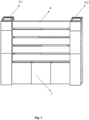
Fig. 1 shows a perspective view of the modular fencing unit made of 2 posts, a plinth and a panel -
Fig. 2.1 shows a cross-section of the foundation and the base -
Fig. 2.2 shows a top view of the base -
Fig. 3.1 shows a perspective view of a post -
Fig. 3.2 shows a perspective view of a post segment -
Fig. 3.3 shows a perspective view of two parts of post segment casing -
Fig. 4 shows a perspective view of a post, a post segment core and a post segment reinforcement -
Fig. 5 shows a cross-section of the foundation, base and post -
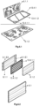
Fig. 6.1 shows a panel made of two parts of panel casing and a frame-type stiffening element -
Fig. 6.2 shows a panel made of two parts of panel casing and a frame-type stiffening element -
Fig. 6.3 shows a panel made from a single panel casing -
Fig. 7.1 shows a post and a plinth -
Fig. 7.2 shows a plinth segment comprising two parts of plinth casing, plinth reinforcement and polystyrene plinth core -
Fig. 8 shows a perspective view of a middle post -
Fig. 9 shows a perspective and top view of a corner post -
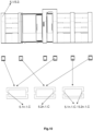
Fig. 10 shows a perspective view of a fencing system and a top view of the corner and middle posts of the system -
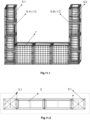
Fig. 11.1 shows a perspective view of the plinth and the two posts of the modular unit -
Fig. 11.2 shows a top view of the base, the plinth and the two posts -
Fig. 12 shows the shape configuration of a middle post on milling lines -
Fig. 13 shows the shape configuration of a corner post on milling lines -
Fig. 14 shows a perspective view of a post segment, according to an embodiment. For ease of representation, the core of the post segment is not shown -
Fig. 15 shows a perspective view of a plinth, according to an embodiment. For ease of representation, the core of the post segment is not shown -
Fig.16 shows a perspective view of the plinth casing, according to the embodiment shown in -
Fig. 15 . For ease of representation, the post segment core is not shown - With reference to
Figure 1 andFigure 2.1 , in a first aspect of the invention, the modular unit configured to be placed on anunderground foundation 1 comprises: threadedmetal rods 2 by means of which it is fixed to abase 3; two posts 5.1, 5.2; and apanel 6 which is mounted between the two posts 5.1 and 5.2. - The threaded
metal rods 2 according to the invention, as shown inFigure 2.1 , are adapted to be fixed in theunderground foundation 1 by means of a chemical anchoring system, each threadedmetal rod 2 having a threaded portion 2.1 whose end is protruding out of theunderground foundation 1. - The number of threaded
metal rods 2 used is an even number which is calculated according to the cross-sectional size of the post. - In a preferred example, 4 rods/post are required for posts with cross-sectional sides between 300 and 500mm.
- In another preferred example of the post, 6 rods/post are required for posts with cross-sectional sides between 500 and 800mm.
- The
base 3 according to the invention, as shown inFigure 2.1 and Figure 2.2 , is formed of a flat metal structure comprising base holes 3.1 correspondingly placed to the threadedmetal rods 2, the base holes 3.1 being configured to allow the threadedmetal rods 2 to pass through. Thebase 3 is fixed to theunderground foundation 1 as shown inFigure 2.1 , by means ofnuts 4 on said threadedmetal rods 2, which pass through the base holes 3.1. - The
base 3 comprises a flat metal structure made of steel pipe with anticorrosive treatment. - Each of the two posts 5.1, 5.2 comprises a plurality of mechanically vertically assembled post segments 5.1n, 5.2n, each post 5.1, 5.2 having a total post volume VST.
-
Figure 3.1 shows a post 5.1 according to the invention, which, in a preferred example, has the shape of a rectangular parallelepiped. - According to the invention, each post segment 5.1n, 5.2n comprises: a post segment casing 5.1n.1, 5.2n.1; a post segment reinforcement 10.1n, 10.2n; and a post segment core 9.1n, 9.2n of polystyrene.
- The advantage of using the post segment core 9.1n, 9.2n of polystyrene is that it contributes to reducing the weight of the post 5.1, 5.2.
- The post segment casing 5.1n.1, 5.2n.1 is essentially shaped as a right-angled prism with an even number of edges and is made of said sandwich-type recyclable material as shown in
Figure 3.2 , having at least one sliding channel 5.1n.1.C, 5.2n.1. Cover the entire height of the respective post segment casing 5.1n.1, 5.2n.1 , thereby forming a sliding channel of each post segment 5.1n, 5.2n having continuity over the entire height of the post resulting from the assembly of post segments 5.1n, 5.2n. - The sandwich-type recyclable material eliminates the need for finishing steps with various types of plaster and the need for finishing tools. Thus, the sandwich-type material ensures a short construction time of the modular delimiting unit and an increased strength to environmental conditions, contributing to the increased lifetime of the modular delimiting unit.
- The post segment casing 5.1n.1, 5.2n.1 comprises one or two post segment casing parts.
Figure 3.3 shows an example in which the post segment casing 5.1n.1 of post 5.1 comprises two parts of post segment casing 5.1n.1.1, 5.1n.1.1.2 joined together and mechanically fastened. - According to the invention, the aforementioned vertical mechanically assembly of the aforementioned post segments 5.1n, 5.2n is realized by means of mechanical joining
elements 12 with rivets or self-drilling screws, as shown inFigure 3.2 . - Each post segment 5.1n, 5.2n according to the invention, as shown in
Figure 4 for post 5.1, comprises post segment reinforcement 10.1n, 10.2n having the same shape as the shape of the post segment casing 5.1n.1, 5.2n.1, the post segment reinforcement 10.1n, 10.2n, placed inside the post segment casing 5.1n, 5.2n.1 , parallel to the faces of the latter, at a distance d1 from the faces of the post segment casing 5.1n.1, the distance d1 being provided by means of post outer spacers 8.2n.1, 8.2n.2 located between the post segment reinforcement 10.1n and the post segment casing 5.1n.1 forming a volume v1 between the post segment reinforcement 10.1n, 10.2n and the post segment casing 5.1n.1, 5.2n.1 , the volume v1 to be filled with afiller material 14, as will be seen below. - The post segment casings 5.1n.1, 5.1n.2 provide strength to the static pressure generated by the
filler material 14. - Each post segment 5.1n, 5.2n according to the invention, as represented in
Figure 4 for post 5.1, comprises the post segment core 9.1n, 9.2n of polystyrene placed inside the post segment reinforcement 5.1n, 5.2n parallel to the faces of the latter, at a distance d2 from the faces of the post segment reinforcement 5.1n, 5.2n.2n, the distance d2 being provided by means of post inner spacers - not shown graphically, located between the post segment core 9.1n, 9.2n and the post segment reinforcement 10.1n, 10.2n, and forming a volume v2 between the post segment core 9.1n, 9.2n and the post segment reinforcement 10.1n, 10.2n which will be filled with thefiller material 14. - The volume v1 together with the
volume v 2 forms the total volume of filler material VbST of the post. Said total volume of filler material VbST of the post is between 25% and 50% of the total post volume VST, thereby realizing an economy of filler material. - The post segment core 9.1n, as shown in
Figure 4 for post 5.1, is formed - in an example, of two sub-segments 9.1n.1, 9.1n.2, configured to be vertically joined together by a x-type fastener 13.1. - Each post 5.1, 5.2 comprises:
- a post cover 13.2.1, 13.2.2 made of said sandwich-type recyclable material, arranged on top of posts 5.1, 5.2 - as shown in
Figure 7.1 for post 5.1, and - mechanical means 13.7 configured for fixing the post segment reinforcement 10.1n, 10.2n on said
base 3. - The posts 5.1, 5.2, according to the invention, are fastened to the
base 3 with a perforated cover-type fastener 13.3, made of said sandwich-type recyclable material, placed between thebase 3 and the posts 5.1, 5.2. Said perforated cover-type fastener 13.3 is provided with holes correspondingly placed to the threadedmetal rods 2, said holes configured to allow the threadedmetal rods 2 to pass through, being mounted on thebase 3 by means of fastening screws 13.3.2 as shown inFigure 5 . - The
panel 6, according to the invention, comprises one or more panel casings 6.1 having substantially rectangular parallelepiped shape and being made of said sandwich-type recyclable material. The panel casing 6.1 are identical or different, depending on the technical requirements, being stiffened by means of panel stiffening elements 13.4. - Each panel casing 6.1, according to the invention, has two sliding elements 6.1.E1, 6.1.E2 corresponding to the sliding channels 5.1.1.C, 5.2.1.C of the two posts 5.1, 5.2, the two sliding elements 6.1.E1LFGL, 6.1.E2LFGL being located on two opposite parallel side faces of the panel casing 6.1 over the entire height of the panel casing 6.1.
- Each panel casing 6.1 according to the invention is stiffened on the inside with panel casing stiffening elements 13.4.
- In an example of the
panel 6, which can be combined with any of the post embodiments, the panel casing 6.1 is formed of two panel casing parts 6.1.1, 6.1.2 joined together and stiffened by means of frame-type stiffening elements 13.4.1 following the contour line of the shape of thepanel 6. The rectangular shape of the frame-type stiffening element 13.4.1 is supported by angled stiffeners 13.4.1.1 and transverse elements 13.4.1.2, as shown inFigures 6.1 and 6.2 . In another example of thepanel 6, which can be combined with any of the post embodiments, the panel casing 6.1 comprises two panel casing parts 6.1.1, 6.1.2 and a frame-type stiffening element 13.4.1 joined together by means of a plurality of mechanical fixing elements, as shown inFigure 6.1 . - In another example of the
panel 6, which can be combined with any of the post embodiments, the panel casing 6.1 is formed by two panel casing parts 6.1.1, 6.1.2 and a frame-type stiffening element 13.4.1 provided with two sliding elements 6.1.E1, 6.1.E2 corresponding to the sliding channels 5.1n.1.1C, 5.2n.1.C of the two posts, the two sliding elements 6.1.E1, 6.1.E2 being located on the two opposite parallel side faces of the panel casing 6.1, over the whole height of the panel casing 6.1, as shown inFigure 6.2 . - In another example of panel, which can be combined with any of the post embodiments, the panel casing 6.1 is made in one part, as shown in
Figure 6.3 . In this case the two parts of panel casing 6.1.1, 6.1.2 form a common body and are provided with two types of stiffeners: end stiffeners, placed on the sides of the panel to support the sliding elements 6.1.E1, 6.1.E2 by means of which the panel is mounted on the sliding channels 5.1n.1.C, 5.2n.1.C of the two posts fixed to them by means of intermediate stiffening members 13.4.2 placed inside the panel. - In a first embodiment of the invention, the post segment reinforcement 10.1n, 10.2n is made of welded mesh.
- The attachment of the post segment reinforcement 10.1n, 10.2n to the
base 3 is made by means of mechanical means 13.7 comprising a plurality of concrete iron bars 11 arranged over the entire height of the post, placed vertically on the edges of each post segment reinforcement 10.1n, 10.2n, between the post segment casing 5.1n.1, 5.1n.2 and the post segment reinforcement 10.1n, 10.2n, eachconcrete iron bar 11 being mechanically fixed, for example by clamps, to the threaded portion of the adjacent threadedmetal rod 2, as shown inFigure 5 . In a second embodiment of the invention, alternative to the first embodiment, as shown inFig. 14 , the post segment reinforcement 10.1n, 10.2n comprises a vertical bar 10.1n1, 10.2n1 corresponding to each edge of the post segment casing 5.1n.1, 5.2n.1, each two adjacent vertical bars 10.1n1, 10.2n1 being connected to each other by horizontal stiffening bars 10.1 n2, 10.2n2. - This embodiment has the advantage of the disassembled character of the posts 5.1, 5.2, the reason for which it is used in situations where it is necessary to disassemble the existing posts 5.1,5.2.
- For the second embodiment of the invention, the flat metal structure of the
base 3 is - in a preferred variant - a frame comprising on the inside two metal guide elements 3.2 parallel to two opposite sides of the frame, the two metal guide elements 3.2 forming together with the said opposite sides of the frame two parallel base guiding channels CG. The post segment reinforcement 10.1n, 10.2n further comprises a flat metal mounting structure 10.1n3, 10.2n3 formed by horizontal stiffening bars 10.1n2, 10.2n2, having the same size and shape as the corresponding portion of the frame of the flat metal structure of thebase 3, said flat metal mounting structure 10.1n3, 10.2n3 placed parallel to the flat metal structure of thebase 3, and forming two parallel reinforcement guiding channels CG together with the respective opposite sides of the flat metal mounting structure 10.1n3, 10.2n3. The parallel base guiding channels CG and the parallel reinforcement guiding channels CG are parallel to each other at a distance d5 from thebase 3. - In this preferred embodiment, the arrangement of the post segment reinforcement 10.1n, 10.2n to the
base 3 is adjustable and is accomplished by mechanical means 13.7 comprising sliding head screws. The reinforcement guiding channels CG are placed correspondingly to the base guiding channels CG, such that the sliding-head screws are configured to slide horizontally in the two parallel base guiding channels CG and in the two parallel reinforcement guiding channels CG, respectively. - The screw is provided with nuts that allow the modular unit components, which in this case are the post segment reinforcement 10.1n, 10.2n and the
base 3, to be fixed in the desired position. The advantage of using sliding-head screws allows the modular unit's components to be fixed in the desired position. - In a further embodiment of the invention, the height of each post segment 5.1n, 5.2n is in the range of 60-70 cm.
- The skilled person will understand, however, that this height will be achieved according to the constructive needs of the area of delimitation, which may require a height of the post segment, for example 50 cm, or another height adapted to the technical conditions imposed by the overall height of the post.
- This embodiment of the invention may be combined with any of the embodiments of posts 5.1, 5.2,
base 3 andpanel 6. - In a further embodiment of the invention, which can be combined with any of the embodiments of the posts 5.1, 5.2, the
base 3 and thepanel 6, the modular area delimiting unit further comprises aplinth 7, as shown inFigure 7.1 . - The
plinth 7 comprises two ormore plinth segments 7n mechanically assembled horizontally. Theplinth segments 7n adjacent to the posts 5.1, 5.2 are fixed to the posts 5.1, 5.2 as follows: thefirst plinth segment 7n is mechanically fixed to the first adjacent post 5.1; thesecond plinth segment 7n is mechanically fixed to thefirst plinth segment 7n.... thelast plinth segment 7n is mechanically fixed to the second adjacent post 5.2. Theplinth segments 7n are mechanically assembled vertically betweenbase 3 andpanel 6. - According to this embodiment of the invention, each
plinth segment 7n comprises: a plinth segment casing 7n.1, 7n.2, a plinth segment reinforcement 10.3n, plinth mechanical means 10.3n4, a plinth segment core 9.3n of polystyrene and a plinth cover 13.6. - The plinth segment casing 7n.1, 7n.2 is essentially rectangular parallelepiped shaped and made of said sandwich-type recyclable material.
- As shown in
Figure 7.2 , the plinth segment reinforcement 10.3n having the same shape as the plinth segment casing 7n.1, 7n.2, is placed inside the plinth segment casing 7n.1, 7n.2, parallel to the faces of the latter at a distance d3 from the faces of the plinth segment casing 7n.1, 7n.2, the distance d3 being provided by means of a plurality of plinth outer spacers 8.4 located between the plinth segment reinforcement 10.3n and the plinth segment casing 7n.1, 7n.2, forming a volume v3 between the plinth segment reinforcement 10.3n and the plinth segment casing 7n.1, 7n.2, which will be filled with thefiller material 14. - The attachment of the plinth segment reinforcement 10.3n to the
base 3 is accomplished with the plinth mechanical means 10.3n4, configured for attachment of the plinth segment reinforcement 10.3n to thebase 3, as shown inFigure 15 . - As represented in
Figure 7.2 , the plinth segment core 9.3n made of polystyrene is placed inside the plinth segment reinforcement 10.3n, parallel to the faces of the latter at a distance d4 relative to the faces of the plinth segment reinforcement 10.3n, the distance d4 being provided by means of a plurality of plinth inner spacers 8.3 located between the plinth segment core 9.3n and the plinth segment reinforcement 10.3n, forming a volume v4 between the plinth segment core 9.3n and the plinth segment reinforcement 10.3n which will be filled with thefiller material 14. - The plinth cover 13.6 made of said sandwich-type recyclable material is arranged at the top of the
plinth 7, as shown inFigure 7.1 . - The volume v3 together with the volume v4 forms the total volume of filler material of the plinth VbSO. The respective total volume of filler material of the plinth VbSO shall be between 25% and 50% of the total volume of the plinth VSO.
- In an example of the plinth, which can be combined with any of the post and panel embodiments, the above-mentioned horizontal mechanical assembling is realized by means of mechanical joining
elements 12, of the rivet or self-drilling screws type. - The embodiment of the invention comprising the plinth has, in turn, a plurality of sub-variants.
- In a first sub-variant of the embodiment of the invention wherein the delimiting unit comprises the plinth, the plinth segment reinforcement 10.3n is made of welded mesh.
- The plinth segment casing 7n.1, 7n.2 comprises two identical plinth segment casing parts 7n.1.1, 7n.1.2, 7n.2.1, 7n.2.2, each made of the respective sandwich type recyclable material. The plinth segment casing parts 7n.1.1, 7n.1.2, 7n.2.1, 7n.2.2 are joined and mechanically fastened together.
- In a second sub-variant of the embodiment of the invention wherein the delimiting unit comprises the plinth, - alternative to the first sub-variant as shown in
figures 15 and 16 , the plinth segment reinforcement 10.3n comprises a horizontal bar of the plinth reinforcement 10.3n1 corresponding to each edge of the plinth segment casing 7n.1, 7n.2, each two adjacent horizontal bars of the plinth reinforcement 10.3n1 being connected to each other by stiffening bars 10.3n. - This embodiment has the advantage of the disassembled character of the
plinth 7, the reason for which it is used in situations where it is necessary to disassemble the existingplinth 7. - For the second sub-variant of the embodiment of the invention wherein the delimiting unit comprises the base - in a preferred embodiment - the flat metal structure of the
base 3 is a frame comprising on the inside two metal guide elements 3.2 parallel to two of the opposite sides of the frame, the two metal guide elements 3.2 forming two parallel base guiding channels CG correspondingly placed to the base guiding channels together with said opposite sides of the frame. - As shown in
figures 15 and 16 , the plinth segment reinforcement 10.3n further comprises a flat metal mounting structure of the plinth reinforcement 10.3n3, formed by stiffening bars of the plinth reinforcement 10.3n2. The flat metal structure for mounting the plinth reinforcement 10.3n3 has the same size and shape as the corresponding portion of the frame of the flat metal structure of thebase 3, said flat metal structure for mounting the plinth reinforcement 10.3n3 being placed parallel to the flat metal structure of thebase 3 and forming two parallel plinth reinforcement guiding channels CG together with the respective opposite sides of the flat metal structure for mounting the plinth reinforcement 10.3n3. The parallel base guiding channels and the parallel reinforcement guiding channels are parallel to each other at a distance d5 from thebase 3. - As shown in
figures 15 and 16 , the plinth mechanical means 10.3n4 comprise sliding head screws which are configured to slide horizontally in the two parallel base guiding channels CG correspondingly placed to the base guiding channels CG and the two parallel plinth reinforcement guiding channels CG thereby allowing the adjustable mounting of the plinth reinforcement 10.3n on thebase 3. - In any of the embodiments of posts 5.1, 5.2,
panel 6,base 3 andplinth 7, the sandwich type recyclable material is composed of a low density polyethylene substrate fixed in full adhesion between two aluminum sheets with characteristics selected from the list below: - (i) the thickness of polyethylene substrate is selected between 2 mm, 3 mm or 5 mm and each aluminum sheet is 0.5 mm thick,
- (ii) the thickness of polyethylene substrate is selected between 2.2 mm or 3.2 mm and each aluminum sheet is 0.4 mm thick,
- (iii) the thickness of polyethylene substrate is selected from 1.4 mm, 2.4 mm or 3.4 mm and each aluminum sheet is 0.3 mm thick,
- (iv) the thickness of polyethylene substrate is selected from the range 1.7 mm - 5.7 mm, and each aluminum sheet has a thickness selected from 0.15 mm or 0.2 mm.
- In any of the embodiments of the posts 5.1, 5.2,
panel 6,base 3 andplinth 7, and the kind of sandwich type recyclable material from which they are made, thefiller material 14 is chosen from concrete, lightweight concrete, aggregates or polyurethane foam. Aggregates within the meaning of the invention include mixtures of sand, gravel, crushed stone, slag and recycled concrete, which are typically used in construction. - The use of concrete or lightweight concrete is particularly advantageous when a very good mechanical strength of the delimiting unit is sought, and the disassembled character of the delimiting unit is not important. Preferably, the embodiments of the invention in which the post segment reinforcement 10.1n, 10.2n and the plinth segment reinforcement 10.3n are made of welded mesh are used in these situations.
- The use of polyurethane foam and aggregate is particularly advantageous when it is intended that the delimiting unit should be easily disassemble. Preferably, in these situations, the embodiments of the invention are used in which the post segment reinforcement 10.1n, 10.2n each comprise a vertical bar of the post segment reinforcement.
- In a second aspect of the invention, an area delimiting system comprising at least two modular area delimiting units according to any example of the post, panel and plinth is provided, wherein the adjacent delimiting units have one of the two posts 5.1 or 5.2, in common.
- In an example of the system, as shown in
Figure 8 , the post 5.1 and/or the post 5.2 is/are common to adjacent modular units. - In a further example of the system, as shown in
Figure 9 , the post 5.1 or 5.2 is a corner post configured for mounting two panels side by side at an angle with the corresponding sliding channels 5.1n.1.C for post 5.1 and 5.2n.1.C for post 5.2, respectively, located on two adjacent faces of the respective post. - In another example of the system, as shown in
Figure 10 , the post 5.1 or 5.2 is the end post, which terminates the delimiting system and has a single sliding channel, i.e. 5.1n.1.C for post 5.1 and 5.2n.1.C for post 5.2, respectively. - In a third aspect of the invention there is provided a method of delimiting an area using the modular unit according to examples, which do not disclose the
plinth 7, the method comprising a plurality of steps as follows:
The first step is the fabrication and mounting of themetal rods 2. - The
metal rods 2 are cut, the threaded portions 2.1 are made for eachmetal rod 2, then are fixed vertically in theunderground foundation 1 by chemical anchoring, with the threaded portion 2.1 protruding out of theunderground foundation 1. - The chemical anchoring systems used for fastening threaded
metal rods 2 can be resin anchor systems, i.e. any of the known systems: capsule systems and injection systems. Both systems comprise two compartments, one filled with a resin and the other with a hardener. - Chemical anchors, according to the invention, are used for fastening threaded
metal rods 2 into theunderground foundation 1. The applied loads are transferred into theunderground foundation 1 by the fixing process between anchor, rod and foundation. The installation procedure comprises two parts - the chemical anchor containing the resin in capsule, cartridge or foil form and the threadedmetal rod 2. - In the case of foundations with voids, a mesh, plastic or metal sieve can be inserted as a third component of the chemical anchoring system.
- Chemical anchors minimize the introduction of stress into the
foundation material 1 due to the absence of expansion forces. - The second step involves the fabrication and mounting of the
base 3. - In this step, the components of the flat metal structure of the
base 3 are cut and welded, whereupon thebase 3 is drilled so that the position of the base holes 3.1 corresponds to the position of the threadedmetal rods 2. Then, positioning thebase 3 so that the threadedmetal rods 2 pass through the base holes 3.1 and fastening thebase 3 by threading thenuts 4 onto the threaded portions 2.1 of the respective threadedmetal rods 2. - If the existing
foundation 1 has irregularities resulting in level differences between the installedbase 3 andfoundation 1, then a layer of concrete for under- pouring or screed is poured to occlude any existing voids between thebase 3 and thefoundation 1. - The third step is the fabrication and mounting of the two posts 5.1, 5.2.
- The fabrication of each post segment reinforcement 10.1n, 10.2n and each post segment 5.1n, 5.2n is carried out in the following sub-steps.
- Initially, two post core sub-segments 9.1n.1, 9.1n.2, 9.2n.1, 9.2n.2 of polystyrene are cut, said sub-segments are joined vertically through the x type fastener 13.1 and are bonded with polyurethane foam to form the post core 9.1n, 9.2n.
- The fastening of each post core sub-segment 9.1n.1, 9.1n.2 inside each post segment reinforcement 10.1n, 10.2n, parallel to the faces of the latter, at a distance d2 from the faces of the post reinforcement 10.1, 10.2, is achieved by means of the post inner spacers.
- Then, each of the post segment reinforcements 10.1n and 10.2n is placed and joined vertically by fixing the adjacent post segment cores 9.1n, 9.2n with polyurethane foam.
- Then each post segment casing 5.1n.1, 5.2n.1 is cut whereupon is milled and bended as follows:
Each post segment casing 5.1n.1, 5.2n.1 is milled and bent over its full height on milling lines for configuring the post shape 5.1n.1.LFCONF, 5.2n.1.LFCONF and on milling lines for configuring said at least one post sliding channel 5.1n.1.LFGL, 5. 2n.1.LFGL. - The number and positioning of the milling lines for configuring the post shape 5.1n.1 .LFCONF, 5.2n.1.LFCONF and the distance between them correspond to the right-angled prism configuration, and the number and positioning of the milling lines for configuring the post sliding channel 5.1n.1.LFGL, 5.2n.1.LFGL and the distance between them correspond to the respective sliding channels 5.1n.1.C, 5.2n.1C.
- Milling the sandwich type material on the milling lines is intended to allow the sandwich type material to bend in the directions of the post edges to create the desired configuration of the post shape 5.1, 5.2.
- Thereafter, each post segment casing 5.1n.1, 5.2n.1 is formed by bending on the milling lines for configuring the post shape 5.1n.1.LFCONF, 5.2n.1.LFCONF and on the milling lines for configuring said at least one post sliding channel 5.1n.1.LFGL, 5. 2n.1.LFGL.
- As shown in
Figures 12 and13 , in an example of posts 5.1, 5.2, which can be combined with any of the embodiments of posts 5.1, 5.2,panel 6,base 3, and the kind of sandwich-type recyclable material from which they are made, the posts 5.1,5.2 have a parallelepiped shape, and the number and positioning of the milling lines 5.1n.1.LFCONF for configuring the shape thereof and the angle of the milling lines of 90 degrees are sized accordingly. - Thus,
Figure 12 shows a middle post with the size of 210.4 x 140 cm, whose shape is configured on the appropriately sized milling lines. -
Figure 13 shows an end post with the size of 198.4 x 140 cm, whose shape is configured on the appropriately sized milling lines. - At the end of this sub-step, the perforated cover type fastener 13.3 is placed for each of the two post segment casings 5.1n.1, 5.2n.1, so that the positioning holes 13.3.1 correspond to the threaded
metal rods 2 and the perforated cover type fastener 13.3 is fixed to thebase 3 by the fastening screws 13.3.2. - In the next sub-step, the post segment casings 5.1n.1, 5.2n.1 are placed and mechanically fastened to the corresponding perforated cover type fasteners 13.3 around the respective post segment reinforcements 10.1n, 10.2n., parallel to the faces of the latter, at a distance d1 from the faces of the respective post segment casing 5.1n.1, 5.2n.1 by means of the post outer spacers 8.2n.1, 8.2n.2, as shown in
Figure 5 . - The fourth step is the fabrication and mounting the
panel 6. - The panel casing 6.1 is cut and then mill and bend it on the milling lines for configuring the shape of the panel 6.1.LFCONF and on the milling lines for configuring the sliding elements of the panel 6.1.E1 LFGL corresponding to at least one sliding channel of the two posts 5.1 n.1.C., 5.2n.1.C, as shown in
Figure 6.3 . - The panel stiffening elements 13.4 are made by cutting, milling, bending and placing them inside the panel casing 6.1 to stiffen the
panel 6. - The shape of
panel 6 and the two sliding elements 6.1.E1LFGL, 6.1.E2LFGL is configured. Next, eachpanel 6 is assembled by sliding the two sliding elements 6.1.E1LFGL, 6.1.E2LFGL on the sliding channels 5.1n.1.C., 5.2n.1.C and fixed to the two posts 5.1, 5.2. - The fifth step is the filling step with filler material.
- In an example, where the casting material is concrete, the concrete is poured both mechanized with a static pump and manually.
- Filling with
concrete 14 is done in steps so as not to overload the casings. As soon as the concrete begins to harden, a new layer may be poured so that it is completely filled to the highest level. - Throughout the operations, the sandwich recyclable material is covered by the protective film from factory. When pouring
concrete 14 plastic film is used for additional protection. - The top post covers 13.2 are made of sandwich type recyclable material, milled and bent, and are installed on the open surfaces where the concrete has been inserted
Figure 7.1 . - In the aforementioned example of the posts 5.1,5.2 , as shown in
Figure 5 , the 12 mm diameter concrete stiffening bars 11 attached to the 4 mm diameter welded mesh reinforcement are fastened with metal collars to the threadedmetal rod 2 anchored in thefoundation 1. In order to access the fastenings from the inside, manhole covers 15 are created on the side faces, fixed in rivets. - For embodiments of the invention in which the post segment reinforcement 10.1n, 10.2n is made of welded mesh, in an embodiment of the method, in
step 3, the manufacture of each post segment reinforcement 10.1n, 10.2n of each post segment 5.1n, 5.2n is carried out by bending and welding the metal mesh. - The vertical positioning and joining of the post segment reinforcements 10.1n, 10.2n comprises fastening the plurality of stiffening bars 11 on the edges of the post segment reinforcements 10.1n, 10.2n.
- The mechanical fastening of the post segment reinforcement 10.1n, 10.2n on the
base 3 comprises fastening eachconcrete stiffening bar 11 to the threaded portion 2.1 of the threadedmetal rod 2 adjacent to the respectiveconcrete stiffening bar 11. - In an example, corresponding to the embodiments of the delimiting unit in which the post segment reinforcement 10.1n, 10.2n each comprise a vertical bar of the post segment reinforcement, in step 2 a frame of horizontal metal bars and two metal guide elements 3.2 parallel to two of the opposite sides of the frame are cut and welded, the two metal guide elements 3.2 forming together with the said opposite sides of the frame two parallel base guiding channels CG.
- In the same above-mentioned example, in
step 3 the manufacture of the post segment reinforcement 10.1n, 10.2n comprises the steps of cutting and welding vertical bars 10.1n1, 10.2n1 connected to each other by horizontal stiffening bars 10.1n2, 10.2n2. - The mounting of the post segment reinforcement 10.1n, 10.2n on
base 3 is carried out by means of sliding-head screws. The positioning of the post segment reinforcement 10.1n, 10.2n on thebase 3 is carried out by means of sliding-head screws provided with one nut on each flat metal mounting structure, respectively on the rectangular flat metal mounting structure of the post segment reinforcement 10.1n3, 10.2n3 and on the flat metal structure of thebase 3, which allow the fastening of the post segment reinforcement 10.1n3, 10.2n3 after adjusting it to the appropriate position. - In an embodiment of the method, as shown in
Figure 11.1 , the method of fabrication the modular area delimiting unit described above further comprises fabrication and mounting aplinth 7. - In the first step, the
metal rods 2 corresponding to theplinth 7 are fabricated and assembled. Themetal rods 2 are cut with the respective threaded portions 2.1, whereupon theunderground foundation 1 is drilled and themetal rods 2 are fixed vertically by chemical anchoring in thefoundation 1, corresponding to the dimensions of theplinth 7, with the threaded portion 2.1 protruding out of theunderground foundation 1. - In the second step the drilling and reinforcement of the
base 3 corresponding to theplinth 7 is carried out, as shown inFigure 11.2 . Thebase 3 is drilled so that the base holes 3.1 are placed corresponding to the threadedmetal rods 2 placed corresponding to the dimensions of theplinth 7. - The threaded
metal rods 2 are placed in the base holes 3.1 and thebase 3 is secured to theunderground foundation 1 by threading thenuts 4 onto the respective threaded portions 2.1. In sub-step 3.1 of the third step, each plinth segment 7.1, 7.2 is manufactured. - The plinth segment casing 7n.1, 7n.2 is cut, milled and bend to full height, in plinth configuration milling lines 7n.1.LFCONF.
- The plinth segment reinforcement 10.3n is manufactured and then the polystyrene plinth core 9.3 is fixed inside the plinth segment reinforcement 10.3n parallel to the faces of the plinth segment reinforcement 10.3n at a distance d4 from the faces of the plinth segment reinforcement 10.3n, the distance d4 being provided by means of the inner plinth spacers 8.3. In sub-step 3.2 of the third step the
plinth segments 7n are assembled. The plinth segment reinforcement 10.3n is mechanically fixed tobase 3. Then the plinth segment casing 7n.1, 7n.2 is placed and mechanically fastened for eachplinth segment 7n on the corresponding perforated type cap fasteners 13.3 around the respective plinth segment reinforcements 10.3n parallel to the faces of the latter, at a distance d4 from the faces of the plinth segment casing 7n.1, 7n.2 by means of the plinth outer spacers 8.4. - The
plinth 7 is made by horizontally joining theplinth segments 7n. - In sub-step 3.3 of the third step, the volume v3 formed between the plinth reinforcement 10.3n and the plinth segment casing 7n.1, 7n.2, as well as the volume v4, formed between the plinth core 9.3n and the plinth reinforcement 10.3, is filled with
filler material 14. - Once the casting of the
filler material 14 has been completed and a minimum of 12 hours has elapsed, the systems securing the position of the casings, i.e. the foil and/or other protective materials, can be removed. The plinth covers 13.6 are made of sandwich-type recyclable material, milled and bent, and mounted on the open surfaces as shown infigure 7.1 . - In another preferred example of the method of fabrication the modular area delimiting unit, wherein the delimiting unit comprises the
plinth 7 having a plinth segment reinforcement 10.3n of welded mesh and the plinth segment casing 7n.1, 7n.2 is made of two casing parts 7n.1.1, 7n.1.2, 7n2.1, 7n2.2, the method further comprises:
In sub-step 3.1, the plinth segment reinforcement 10.3n is fabricated by bending and welding its metal mesh, whereupon the polystyrene plinth core 9.3 is fixed inside the plinth segment reinforcement 10.3n parallel to the faces of the latter at distance d4. - Each of the two identical parts of plinth segment casing 7n.1.1, 7n.1.2, 7n2.1, 7n2.2 is cut, then each part is milled and bend to full height, in plinth configuration milling lines 7n.1.LFCONF.
- In sub-step 3.2 of the third step, the parts of the plinth segment casing 7n.1.1, 7n.1.2, 7n2.1, 7n2.2 are placed and mechanically fastened on the corresponding perforated cover type fasteners 13.3, around the respective plinth segment reinforcements 10.3n parallel to the faces of the latter, at a distance d4 from the faces of the plinth segment casing 7n.1.1, 7n.1.2, 7n2.1, 7n2.2, the distance d4 being ensured by means of the plinth outer spacers 8.4.
- In sub-step 3.3 of the third step the filling of volumes v3 and v4 of
plinth 7 is carried out with concrete. - In another preferred embodiment of the method of fabrication the modular area delimiting unit, with reference to
figures 15 and 16 , wherein the delimiting unit comprises theplinth 7, in sub-step 3.1, the manufacture of the plinth segment reinforcement 10.3n is carried out as follows: As shown infigures 15 and 16 , first the horizontal bars of the plinth reinforcement 10.3n1 are cut and weld corresponding to each edge of the plinth segment casing 7n.1, 7n.2, each two adjacent horizontal bars of the plinth reinforcement 10.3n1 being connected to each other by stiffening bars 10.3n2, so that the stiffening bars 10.3n2 form a flat metal structure for mounting the plinth reinforcement 10.3n3, having the same size and shape as the flat metal structure of thebase 3. - In this embodiment, as shown in
figure 15 , the mechanical attachment of the plinth to the post is achieved by means of supports 13.8 which are mounted to the post with self-drilling screws, pop rivets or other suitable mechanical fastening systems. - In the embodiment shown in
figure 16 , the flat metal structure for mounting the plinth reinforcement 10.3n3 is placed parallel to the flat metal structure of thebase 3 at a distance d5 from thebase 3, so as to form two parallel guiding channels CG for plinth reinforcement together with the respective opposite sides of the flat metal structure for mounting the plinth reinforcement 10.3n3. - The plinth reinforcement 10.3n3 is then mounted on the
base 3 by means of sliding head screws configured to slide horizontally in the two parallel guiding channels CG of the base and in the two parallel guiding channels CG of the plinth reinforcement thus allowing the adjustable mounting of the plinth reinforcement 10.3n on thebase 3. Each sliding head bolt is provided with a nut on each flat metal mounting structure, respectively on the rectangular flat metal mounting structure of the plinth segment reinforcement 10.3n and on the flat metal structure of thebase 3, which allow the fastening of the plinth reinforcement 10.3n3 on thebase 3 after adjusting it to the appropriate position. - The person skilled in the art will understand that other types of systems can be used which allow the horizontal sliding of the post segment reinforcement 10.1n, 10.2n or the plinth reinforcement 10.3n3 on the
base 3 and their adjustable mounting, such as: roller sliding systems, gliders with fastening fins or similar. - The person skilled in the art will understand that there may be several possible embodiments of the posts 5.1,5.2 and its sub-components, the
panel 6, theplinth 7 as well as modular systems covered by the present invention, by combining examples and embodiments according to the configuration of the surface to be bounded and the angle between the sides of the polygonal surface to be bounded. -
- 1 underground foundation
- 2 threaded metal rods
2.1. threaded portion of threaded metal rod - 3 base
- 3.1 base holes
- 3.2 metallic elements
- 4 base fastening nut
- posts
- 5.1, 5.2 posts
- 5.1n, 5.2n post segments
- 5.1n.1 post segment casing for the first post
- 5.1n.1.1 first post segment casing part for the first post
- 5.1n.1.2 second post segment casing part for the first post
- 5.1n.1.C sliding channel of the post casing for the first post
- 5.1n.1.LFCONF milling lines for configuring the first post shape
- 5.1n.1.LFGL milling lines for configuring the sliding channel of the first post
- 5.2n.1 post segment casing for each segment of the second post not shown graphically
- 5.2n.1.C sliding channel of the post casing for the second post
- 5.2n.1.LFCONF milling lines for configuring the second post shape
- 5.2n.1.LFGL milling lines for configuring the sliding channel for the second post
- 5.1n.1 post segment casing for the first post
- 6 panel
6.1 panel casings- 6.1.1 first part of panel casing
- 6.1. 2 second part of panel casing
- 6.1.E1 a first joining element of the panel casing
- 6.1 E2 a second joining element of the panel casing
- 6.1.LFCONF milling lines for configuring the panel shape
- 6.1.E1LFGL, 6.1.E2LFGL milling lines for configuring the sliding elements of the panel
- 7 plinth
- 7n plinth segments
- 7n.1 plinth segment casing for the first plinth segment
- 7n.1.1 first part of plinth segment casing
- 7n.1.2 second part of the plinth casing of the first plinth segment
- 7n.1.LFCONF milling line for plinth configuration
- 7n.2 plinth segment casing for a second plinth segment
- 7n.2.1 first casing part of the first plinth segment
- 7n.2.2 second casing part of the first plinth segment
- 7n.2.LFCONF milling line for plinth configuration
- spacers
- 8.2n.1 outer spacers for the first post
- 8.2n.2 outer spacers for the second post
- 8.3 inner plinth spacers
- 8.4 plinth outer spacers
- polystyrene core
- 9.1, 9.2 polystyrene post core
9.1n; 9.2n polystyrene post segment core- 9.1n.1 first post core sub-segment for the first post
- 9.1n.2 second post core sub-segment for the first post
- 9.2n.1 first post-core sub-segment for the second post - not shown in the drawings
- 9.2n.2 second post core sub-segment for the second post - not shown in the drawings
- 9.3. polystyrene plinth core
9.3n polystyrene plinth segment core
- 9.1, 9.2 polystyrene post core
- welded mesh reinforcement
- 10.1, 10.2 reinforcements for first and second posts
- 10.1n post segment reinforcement for the first post
- 10.1n1 vertical bar of post segment reinforcement for the first post
- 10.1n2 horizontal stiffening bar of post segment reinforcement for the first post
- 10.1n3 rectangular flat metal structure for mounting the post segment reinforcement for the first post
- 10.2n post segment reinforcement for the second post, not shown in the drawings
- 10.2n1 vertical bar of post segment reinforcement for the second post
- 10.2n2 horizontal stiffening bars of the post segment reinforcement for the second post
- 10.2n3 rectangular flat metal structure for mounting the post segment reinforcement for the second post
- 10.1n post segment reinforcement for the first post
- 10.3 plinth reinforcement
10.3n plinth segment reinforcement- 10.3n1 horizontal bar of plinth segment reinforcement
- 10.3n2 stiffening bar for segment reinforcement
- 10.3n3 rectangular flat metal structure for mounting the plinth segment reinforcement
- 10.3n4 plinth mechanical means configured for attachment of the plinth segment reinforcement to the base
- 10.1, 10.2 reinforcements for first and second posts
- 11 concrete iron bars
- 12 elements for mechanically joining fastening of post segments fasteners and reinforcements
- 13.1 fasteners type x
- 13.2 post top cover type fasteners
- 13.2.1.top post cover for the first post
- 13.2.2. top post cover for second post
- 13.3 perforated cover type fasteners
- 13.3.1 positioning holes
- 13.3.2. screws for fastening the perforated cover type fastener,
- 13.4 panel casing stiffening elements
- 13.4.1 frame-type stiffening element
- 13.4.1.1 angled stiffener
- 13.4.1.2 transversal element
- 13.4.2 intermediate stiffening element
- 13.4.1 frame-type stiffening element
- 13.5 frame type fasteners between the two plinth casing parts
- 13.6 plinth cover
- 13.7 mechanical means for attaching the post segment reinforcement or the plinth segment reinforcement on the base
- 13.8. supports for fastening the plinth to the post
- CG - base guiding channels, reinforcement guiding channels, post guiding channels and plinth guiding channels
- 14 concrete filler material
- 15 post manhole cover
- distances not graphically shown
d1, d2, d3, d4, d5 - volumes not graphically shown
- v, v2, v3,v4
- VST total volume of the post
- VbST total concrete volume of the post
- VSO total volume of the plinth
- VbSO total concrete volume of the plinth
Claims (15)
- A modular area delimiting unit, configured to sit on an underground foundation (1), characterized in that the modular area delimiting unit comprises:a. vertical threaded metal rods (2), adapted to be fixed in the underground foundation (1) by means of a chemical anchoring system, each threaded metal rod having a threaded portion (2.1) protruding outside the underground foundation (1),b. a base (3) formed of a flat metal structure, comprising base holes (3.1), which are positioned accordingly to the threaded metal rods (2), the base holes (3.1) being configured to allow the threaded metal rods (2) to pass through, the base (3) being configured to be fixed on the underground foundation (1) by means of nuts (4) on said threaded portions (2.1) of the threaded metal rods (2),c. two posts (5.1, 5.2), each post (5.1, 5.2) comprising a plurality of post segments (5.1n, 5.2n), which are mechanically assembled in the vertical direction, each post (5.1, 5.2) having a total post volume VST,d. a panel (6) fixed between the two posts (5.1, 5.2),and in that each post segment (5.1n, 5.2n ) comprises:- a post segment casing (5.1n.1, 5.2n.1) essentially in the shape of a right-angled prism with an even number of edges, made of a sandwich type recyclable material, having at least one sliding channel (5.1n.1.C, 5.2n.1.C) running the full height of the respective post segment casing (5.1n.1, 5.2n.1),- a post segment reinforcement (10.1n, 10.2n) having the same shape as the post segment casing (5.1n.1, 5.2n.1), the post segment reinforcement (10.1n, 10.2n) being positioned inside the post segment casing (5.1n.1, 5.2n.1), parallel to the faces of the latter at a distance d1 from the faces of the post segment casing (5.1n.1, 5.2n.1), the distance d1 being provided by means of post outer spacers (8.2n.1, 8.2n.2) located between the post segment reinforcement (10.1n, 10.2n) and the post segment casing (5.1n.1, 5.2n.1), forming a volume v1 between the post segment reinforcement (10.1n, 10.2n) and the post segment casing (5.1n.1, 5.2n.1),- a post segment core (9.1n, 9.2n) of polystyrene, placed inside the post segment reinforcement (10.1n, 10.2n), parallel to the faces of the latter at a distance d2 from the faces of the post segment reinforcement (10.1n, 10.2n), the distance d2 being provided by means of post inner spacers located between the post segment core (9.1n, 9.2n) and the post segment reinforcement (10.1n, 10.2n), forming a volume v2 between the post segment core (9.1n, 9.2n) and the post segment reinforcement (10.1n, 10.2n),and in that each post (5.1, 5.2) comprises:- a post cover (13.2.1, 13.2.2) made of said sandwich-type recyclable material, placed on top of the posts (5.1, 5.2),- mechanical means (13.7) configured for fixing the post segment reinforcement (10.1n, 10.2n) to the base (3),and in that each post (5.1, 5.2) is configured to be fixed to the base (3) with a perforated cover-type fastener (13.3) made of said sandwich-type recyclable material, placed between the base (3) and the post (5.1, 5.2),said perforated cover-type fastener (13.3) comprising holes placed correspondingly to threaded metal rods (2) and configured to allow the passage of threaded metal rods (2), said perforated cover-type fastener (13.3) being mounted on the base (3) by means of fastening screws (13.3.2),and in that the panel (6) comprises one or more panel casing (6.1) having the shape of an essentially rectangular parallelepiped:- each panel casing (6.1) is made of said sandwich-type recyclable material,- each panel casing (6.1) having two sliding elements (6.1.E1, 6.1.E2) corresponding to the sliding channels (5.1.1.C, 5.2.1.C) of the two posts (5.1, 5.2), said two sliding elements (6.1.E1LFGL, 6.1.E2LFGL) being situated on two opposite parallel sides of the panel casing (6.1) over the entire its height,- each panel casing (6.1) being internally stiffened with panel casing stiffening elements (13.4)and in that the volume v1 and the volume v2 are configured to be filled with a filler material (14) so as to form a total volume of post filler material (VbST) = v1+v2 of between 25% and 50% of the total post volume (VST).
- The modular area delimiting unit according to claim 1,
wherein:- the post segment reinforcement (10.1n, 10.2n) is made of welded mesh and wherein:- said mechanical means (13.7) comprise a plurality of concrete iron bars (11) arranged over the entire height of the posts (5.1, 5.2), placed vertically on the edges of each post segment reinforcement (10.1n, 10.2n) between the post segment casing (5.1n.1, 5.2n.1) and the post segment reinforcement (10.1n, 10.2n), and each concrete iron bar (11) is configured to be mechanically fixed to the threaded portion of the adjacent threaded metal rod (2). - The modular area delimiting unit according to claim 1
wherein- the post segment reinforcement (10.1n, 10.2n) comprises one vertical bar of the post segment reinforcement (10.1n1, 10.2n1) corresponding to each edge of the post segment casing (5.1n.1, 5.2n.1), each two adjacent vertical bars of the post segment reinforcement (10.1n1, 10.2n1) being connected to each other by horizontal stiffening bars (10.1n2, 10.2n2). - The modular area delimiting unit according to claim 3, wherein- the flat metal structure of the base (3) is a frame comprising on the inside two metal guiding elements (3.2) parallel to two opposite sides of the frame, said two metal guide elements (3.2) forming two parallel post guiding channels CG together with said opposite sides of the frame,- the post segment reinforcement (10.1n, 10.2n) further comprising a flat metal mounting structure (10.1n3, 10.2n3) formed by horizontal stiffening bars (10.1n2, 10.2n2) having the same size and shape as the frame of the flat metal structure of the base (3), said flat metal mounting structure (10.1n3, 10.2n3) placed parallel to the flat metal structure of said base (3) at a distance d5 from the base (3), and forming two parallel reinforcement guiding channels CG together with the respective opposite sides of the flat metal mounting structure (10.1n3, 10.2n3),- the mechanical means (13.7) comprise sliding-head screws configured to slide horizontally in said two parallel base guiding channels CG and in said two parallel reinforcement guiding channels CG, respectively, thereby enabling the adjustable mounting of the post segment reinforcement (10.1n, 10.2n) on the base (3).
- The modular area delimiting unit according to any one of the preceding claims, wherein the height of each post segment (5.1n, 5.2n) is in the range of 60-70 cm.
- The modular area delimiting unit according to any one of the previous claims, further comprising a plinth (7) comprising two or more plinth segments (7n) which are mechanically assembled in the horizontal direction, said plinth (7) having a total plinth volume (VSO), whereinthe plinth segments (7n) adjacent to the posts (5.1, 5.2) are fixed to them,and whereinthe plinth segments (7n) are mechanically assembled between the base (3) and the panel (6),and whereineach plinth segment (7n) comprises:- a plinth segment casing (7n.1, 7n.2) of substantially rectangular parallelepiped shape, made of said sandwich-type recyclable material- a plinth segment reinforcement (10.3n) having the same shape as the plinth segment casing (7n.1, 7n.2), positioned inside the plinth segment casing (7n.1, 7n.2), parallel to the faces of the latter at a distance d3 from the faces of the plinth segment casing (7n.1, 7n.2), said distance d3 being provided by means of a plurality of plinth outer spacers (8.4) located between the plinth segment reinforcement (10.3n) and the plinth segment casing (7n.1, 7n.2), forming a volume v3 between the plinth segment reinforcement (10.3n) and the plinth segment casing (7n.1, 7n.2),- plinth mechanical means (10.3n4) configured for fixing the plinth segment reinforcement (10.3n) on said base (3)- a plinth segment core (9.3n) of polystyrene, positioned inside the plinth segment reinforcement (10.3n), parallel to the faces of the latter at a distance d4 from the faces of the plinth segment reinforcement (10.3n), said distance d4 being provided by means of a plurality of plinth inner spacers (8.3) located between the plinth segment core (9.3n) and the plinth segment reinforcement (10.3n), forming a volume v4 between the plinth segment core (9.3n) and the plinth segment reinforcement (10.3n),- a plinth cover (13.6) made of said sandwich-type recyclable material, arranged at the top of the plinth (7),and whereinsaid volume v3 and said volume v4 are configured to be filled with filler material (14) so as to form a total volume of plinth filler material (VbSO) = v3+v4 of between 25% and 50% of the plinth total volume (VSO).
- The modular area delimiting unit according to claim 6, wherein- the plinth segment reinforcement (10.3n) is made of welded mesh,- the plinth segment casing (7n.1, 7n.2) comprises two identical parts of plinth segment casing (7n.1.1, 7n.1.2, 7n.2.1, 7n.2.2), each of which made of said sandwich-type recyclable material, said two parts of plinth segment casing (7n.1.1, 7n.1.2, 7n.2.1, 7n.2.2) being mechanically joined and fastened together.
- The modular area delimiting unit according to claim 6, wherein- the plinth segment reinforcement (10.3n) comprises one horizontal bar of the plinth reinforcement (10.3n1) corresponding to each edge of the plinth segment casing (7n.1, 7n.2), each two adjacent horizontal bars of the plinth reinforcement (1 0.3n1) being connected to each other by stiffening bars (10.3n2).
- The modular area delimiting unit according to any one of the previous claims, wherein said sandwich-type recyclable material comprises a low density polyethylene substrate fixed in full adhesion between two aluminum sheets having characteristics selected from the list below:(v) the thickness of polyethylene substrate is selected from 2 mm, 3 mm or 5 mm and each aluminum sheet is 0.5 mm thick,(vi) the thickness of polyethylene substrate is selected from 2.2 mm or 3.2 mm and each aluminum sheet is 0.4 mm thick,(vii)the thickness of polyethylene substrate is selected from 1.4 mm, 2.4 mm or 3.4 mm and each aluminum sheet is 0.3 mm thick,(viii)the thickness of polyethylene substrate is selected from the range 1.7 mm - 5.7 mm, and each aluminum sheet has a thickness selected from 0.15 mm or 0.2 mm.
- The modular area delimiting unit according to any one of the previous claims, wherein the filler material (14) is selected from concrete, lightweight concrete, aggregate or polyurethane foam.
- An area delimiting system comprising at least two modular area delimiting units according to any one of the previous claims, wherein the adjacent delimiting units have in common one of the two posts (5.1, 5.2).
- A method of fabrication the modular area delimiting unit according to claims 1 to 5 and 9 - 10,
characterized in that it comprises the following steps:STEP 1 Fabrication and mounting of said threaded metal rods (2):- Cutting said threaded metal rods (2) and forming the respective threaded portions (2.1),- Drilling into the underground foundation (1) and vertically fastening therein said threaded metal rods (2) by chemical anchoring, with the threaded portion (2.1) protruding outside the underground foundation (1),STEP 2 Fabrication and mounting the base (3):- Cutting and welding the components of the flat metal structure of the base (3),- Drilling the base (3) so that the position of the base holes (3.1) corresponds to the position of the threaded metal rods (2) fixed in the underground foundation (1),- Positioning the base (3) so that the threaded metal rods (2) pass through the base holes (3.1),- Fastening the base (3) by threading the nuts (4) onto the threaded portions (2.1) of the respective threaded metal rods (2),STEP 3 Fabrication and mounting of the two posts (5.1, 5.2):- Fabrication of each post segment reinforcement (10.1n, 10.2n) of each post segment (5.1n, 5.2n),- Cutting and fastening of each polystyrene post segment core (9.1n, 9.2n) of each post segment (5.1n, 5.2n) inside each post segment reinforcement (10.1n, 10.2n) parallel to the faces of the latter at a distance d2 from the faces of the post segment reinforcement (10.1n, 10.2n) by means of the post inner spacers,- Vertical positioning and joining the post segment reinforcements (10.1n, 10.2n) adjacent to the plurality of post segments (5.1n, 5.2n) and fixing the polystyrene post segment cores (9.1n, 9.2n) with polyurethane foam,- Cutting of each post segment casing (5.1n.1, 5.2n.1) of each post segment (5.1n, 5.2n),- Vertical milling and bending of each post segment casing (5.1n.1, 5.2n.1) on milling lines for configuring the shape of the post (5.1n.1.LFCONF, 5.2n.1.LFCONF) and on milling lines for configuring said post sliding channel (5.1n.1.LFGL, 5.2n.1.LFGL), the number, the positioning of the milling lines for configuring the shape of the post (5.1n.1.LFCONF, 5.2n.1.LFCONF) and the distance between them corresponding to the right-angled prism configuration, the number, the positioning of the milling lines for configuring said post sliding channel (5.1n.1.LFGL, 5.2n.1.LFGL), and the distance between them corresponding to the at least one sliding channel (5.1n.1.C, 5.2n.1.C),- Positioning the perforated cover-type fastener (13.3) for each of the two post segment casings (5.1n.1, 5.2n.1) so that the positioning holes (13.3.1) correspond to the threaded metal rods (2) and fastening it to the base (3) by means of the fastening screws (13.3.2),- Mechanically fastening of the post segment reinforcement (10.1n, 10.2n) to the base (3),- Vertical positioning and mechanically fastening of the post segment casings (5.1n.1, 5.2n.1) of the plurality of post segment (5.1n, 5.2n) on the corresponding perforated cover-type fasteners (13.3) around the respective post segment reinforcement (10.1n, 10.2n), parallel to the faces of the latter, at a distance d1 from the faces of the post segment casings (5.1n.1, 5.2n.1) by means of the outer post spacers (8.2n.1 , 8.2n.2),STEP 4 Fabrication and mounting the panel (6)- Cutting the panel casing (6.1),- Milling and bending the panel casing (6.1) on the milling lines for configuring the panel shape (6.1.LFCONF) and on the milling lines for configuring the panel sliding elements (6.1.ELFGL) corresponding to the sliding channels (5.1n.1.C., 5.2n.1.C) of the posts,- Cutting, milling, bending and positioning the panel casing stiffening elements (13.4) and positioning them inside the panel casing (6.1),- Configuring the shape of the panel (6.1) and of the two sliding elements (6.1.E1LFGL, 6.1.E2LFGL),- Mounting and fastening each panel (6) by sliding the two sliding elements (6.1.E1LFGL, 6.1.E2LFGL) corresponding to the sliding channels (5.1n.1.C., 5.2n.1.C) of the posts,- Cutting, milling, bending and positioning the panel casing stiffening elements and positioning them inside the panel casing,- Configuring the shape of the panel and of the two sliding elements,- Mounting and fastening each panel by sliding the two sliding elements onto the corresponding sliding channels of the posts.STEP 5 Filling each post (5.1, 5.2) with filler material:- Filling the volume v1 and the volume v2 with filler material (14),- Mounting and fastening the post covers (13.2). - The method of fabrication the modular area delimiting unit according to claim 12 wherein: In STEP 3 - Fabrication of each post segment reinforcement (10.1n, 10.2n) of each post segment (5.1n, 5.2n) is accomplished by bending and welding the metal mesh,- The vertical positioning and joining of the post segment reinforcements (10.1n, 10.2n) comprise fastening the plurality of stiffening bars (11) on the edges of the post segment reinforcements (10.1n, 10.2n),- The mechanically fastening of the post segment reinforcement (10.1n, 10.2n) to the base (3) comprises fastening each concrete iron bar (11) to the threaded portion (2.1) of the threaded metal rod (2) adjacent to the respective concrete iron bar (11).
- The method of fabrication the modular area delimiting unit according to claim 12 or 13, wherein a plinth (7) is further fabricated and assembled by the following sub-steps:In STEP 1 - SUB-STEP 1 - Fabrication and mounting of threaded metal rods (2) corresponding to the plinth (7):- Cutting the threaded metal rods (2) and forming the respective threaded portions (2.1),- Drilling the underground foundation (1) and vertical fastening of the threaded metal rods (2) into it by means of chemical anchoring corresponding to the dimensions of the plinth (7), with the threaded portion (2.1) protruding outside the underground foundation (1),In STEP 2 - Drilling and mounting the base (3) corresponding to the plinth (7):- Drilling the base (3) so that the base holes (3.1) are placed corresponding to the threaded metal rods (2) placed corresponding to the dimensions of the plinth (7);- Positioning the threaded metal rods (2) in the base holes (3.1) and fastening the base (3) to the underground foundation (1) by threading nuts (4) onto the respective threaded portions (2.1),STEP 3 - SUB-STEP 3.1. Fabrication of each plinth segment (7n):- Cutting the plinth segment casing (7n.1, 7n.2)- Milling and bending each part of plinth segment casing (7n.1, 7n.2), on full height, on plinth configuration milling lines (7n.1.LFCONF),- Fabrication of plinth segment reinforcement (10.3n),- Fastening the polystyrene plinth segment core (9.3n) inside the plinth segment reinforcement (10.3n) parallel to the faces of the latter at a distance d4 from the faces of the plinth segment reinforcement (10.3n), the distance d4 being provided by means of the plinth inner spacers (8.3),STEP 3 - SUB-STEP 3.2. Assembling the plinth segments (7n):- Mechanically fastening of the plinth segment reinforcement (10.3n) to the base (3),- Positioning and mechanically fastening of the plinth segment casing (7n.1., 7n.2) on the corresponding perforated cover-type fasteners (13.3), around the respective plinth segment reinforcements (10.3n) parallel to the faces of the latter, at a distance d4 from the faces of the plinth segment casing (7n.1, 7n.2), the distance d4 being provided by means of the plinth outer spacers (8.4),- Horizontal joining of plinth segments (7n.1, 7n.2),STEP 3 - SUB-STEP 3.3. Filling the plinth with filler material (7)- Filling the volumes v3 and v4 with filler material (14),- Mounting and fastening the plinth covers (13.6).
- The method of fabrication the modular area delimiting unit according to claim 14, wherein:In STEP 3 - SUB-STEP 3.1. Fabrication of each plinth segment (7n):- Cutting of the plinth segment casing (7n.1 , 7n.2) is accomplished by cutting the two identical parts of plinth segment casings (7n.1.1, 7n.1.2; 7n2.1, 7n2.2) and milling and bending each one to its full height on the plinth configuration milling lines (7n.1.LFCONF),- Fabrication of the plinth segment reinforcement (10.3n) by bending and welding the metal mesh,In SUB-STEP 3.2. Assembling of plinth segments (7n):- Positioning and mechanically fastening of the plinth segment casing (7n.1., 7n.2.) is achieved by positioning and mechanically fastening of the plinth segment casing parts.
andIn SUB-STEP 3.3. Filling the plinth with filler material (7)
The filling of the volumes v3 and v4 with filler material (14) is carried out by cutting out the two identical parts of plinth segment shells (7n.1.1, 7n.1.2; 7n2.1, 7n2.2) and milling and bending each one over its full height on plinth configuration milling lines (7n.1.LFCONF),- Fabrication of the plinth segment reinforcement (10.3n) by bending and welding the metal mesh,In SUB-STEP 3.2. Assembly of plinth segments (7n):- Positioning and mechanically fastening of the plinth segment casing (7n.1., 7n.2.) is accomplished by positioning and mechanically fastening of the plinth segment casing parts, andIn SUB-STEP 3.3. Filling the plinth with filler material (7)- Filling the volumes v3 and v4 with filler material (14) is accomplished with concrete.
Applications Claiming Priority (1)
| Application Number | Priority Date | Filing Date | Title |
|---|---|---|---|
| ROA202300627A RO137963A0 (en) | 2023-10-30 | 2023-10-30 | Modular unit, surface delimiting system and method for making them |
Publications (1)
| Publication Number | Publication Date |
|---|---|
| EP4549684A1 true EP4549684A1 (en) | 2025-05-07 |
Family
ID=89983946
Family Applications (1)
| Application Number | Title | Priority Date | Filing Date |
|---|---|---|---|
| EP24209454.8A Pending EP4549684A1 (en) | 2023-10-30 | 2024-10-29 | Modular area delimiting unit and method of fabrication thereof, and corresponding area delimiting system |
Country Status (2)
| Country | Link |
|---|---|
| EP (1) | EP4549684A1 (en) |
| RO (1) | RO137963A0 (en) |
Citations (7)
| Publication number | Priority date | Publication date | Assignee | Title |
|---|---|---|---|---|
| CN101906900A (en) * | 2010-08-06 | 2010-12-08 | 天津市津科智博科技发展有限公司 | Fence structure |
| WO2014164537A1 (en) * | 2013-03-11 | 2014-10-09 | Dickerson Michael Albert | Custom lightweight wall or fence |
| US20150275542A1 (en) * | 2006-01-31 | 2015-10-01 | Kevin P. Kelly | Modular Wall System |
| GB2554506A (en) * | 2016-07-11 | 2018-04-04 | Modular Innovations Pty Ltd | Improved panel and post systems |
| CN212583433U (en) * | 2020-05-14 | 2021-02-23 | 中国水利水电第八工程局有限公司 | Prefabricated enclosure foundation and connection structure of prefabricated enclosure foundation and enclosure upright column |
| JP6862022B1 (en) | 2020-09-01 | 2021-04-21 | 株式会社コンクレタス | Fence foundation, fence, fence construction method and formwork |
| RO135078A2 (en) | 2019-12-18 | 2021-06-30 | Bruno Christian Albert | Modular fence system made of prefabricated components |
-
2023
- 2023-10-30 RO ROA202300627A patent/RO137963A0/en unknown
-
2024
- 2024-10-29 EP EP24209454.8A patent/EP4549684A1/en active Pending
Patent Citations (7)
| Publication number | Priority date | Publication date | Assignee | Title |
|---|---|---|---|---|
| US20150275542A1 (en) * | 2006-01-31 | 2015-10-01 | Kevin P. Kelly | Modular Wall System |
| CN101906900A (en) * | 2010-08-06 | 2010-12-08 | 天津市津科智博科技发展有限公司 | Fence structure |
| WO2014164537A1 (en) * | 2013-03-11 | 2014-10-09 | Dickerson Michael Albert | Custom lightweight wall or fence |
| GB2554506A (en) * | 2016-07-11 | 2018-04-04 | Modular Innovations Pty Ltd | Improved panel and post systems |
| RO135078A2 (en) | 2019-12-18 | 2021-06-30 | Bruno Christian Albert | Modular fence system made of prefabricated components |
| CN212583433U (en) * | 2020-05-14 | 2021-02-23 | 中国水利水电第八工程局有限公司 | Prefabricated enclosure foundation and connection structure of prefabricated enclosure foundation and enclosure upright column |
| JP6862022B1 (en) | 2020-09-01 | 2021-04-21 | 株式会社コンクレタス | Fence foundation, fence, fence construction method and formwork |
Also Published As
| Publication number | Publication date |
|---|---|
| RO137963A0 (en) | 2024-02-28 |
Similar Documents
| Publication | Publication Date | Title |
|---|---|---|
| AU2017203291B2 (en) | Stronger wall system | |
| US6301851B1 (en) | Apparatus and method for forming precast modular units and method for constructing precast modular structure | |
| US20030005650A1 (en) | Composite retaining wall and construction method for underground structure | |
| US12398561B2 (en) | Systems and methods for coupling prefabricated panels together and reinforcing frame structure | |
| KR101672924B1 (en) | Fire proof reinforced panel using high strength steel plate and construction method of the same | |
| US5724782A (en) | System and method for constructing buildings (and other structures) capable of withstanding substantial natural forces | |
| TW588138B (en) | Wall panel | |
| KR102496473B1 (en) | Seismic Resistant Structure Attaching A External PC Wall Panel Having Anchor Through Hole And Construction Method Thereof | |
| CN111851857B (en) | Single-sided prefabricated concrete steel wire grid insulation board wall and construction method thereof | |
| US10934709B2 (en) | Prefabricated self-supporting module for making building structures, more particularly swimming pools | |
| JP2001207529A (en) | Structure of steel building | |
| KR101908943B1 (en) | RC WALL STRUCTURE FOR TOP-DOWN AND METHOD FOR CONSTRUCTING THE STRUCTUREa | |
| AU2020200564A1 (en) | Integrated formwork method for concrete structures | |
| US7146775B2 (en) | Wall system | |
| JPH0444541A (en) | Steel frame-reinforced concrete structure and building | |
| JP7781155B2 (en) | Reinforced modular steel and concrete structure | |
| JP2691208B2 (en) | Steel wall formwork panel and steel wall formwork for nuclear facility building | |
| KR200234163Y1 (en) | Construction structure of pillar for building structure | |
| DE29714310U1 (en) | Precast concrete wall equipment | |
| KR102256173B1 (en) | Seismic and Thermal Reinforcing Structure and Construction Method Thereof | |
| JP2802612B2 (en) | Underwater formwork method | |
| JPH0633515A (en) | Frame construction method for prestressed steel pipe concrete structure | |
| JPH03501280A (en) | Method of constructing concrete columns for platforms or similar structures and column parts for similar uses | |
| JP3153468B2 (en) | Construction method of concrete structure | |
| JP2003161041A (en) | Seismic reinforcement structure of existing building and its construction method |
Legal Events
| Date | Code | Title | Description |
|---|---|---|---|
| PUAI | Public reference made under article 153(3) epc to a published international application that has entered the european phase |
Free format text: ORIGINAL CODE: 0009012 |
|
| STAA | Information on the status of an ep patent application or granted ep patent |
Free format text: STATUS: THE APPLICATION HAS BEEN PUBLISHED |
|
| AK | Designated contracting states |
Kind code of ref document: A1 Designated state(s): AL AT BE BG CH CY CZ DE DK EE ES FI FR GB GR HR HU IE IS IT LI LT LU LV MC ME MK MT NL NO PL PT RO RS SE SI SK SM TR |
|
| STAA | Information on the status of an ep patent application or granted ep patent |
Free format text: STATUS: REQUEST FOR EXAMINATION WAS MADE |
|
| 17P | Request for examination filed |
Effective date: 20251107 |
|
| GRAP | Despatch of communication of intention to grant a patent |
Free format text: ORIGINAL CODE: EPIDOSNIGR1 |
|
| STAA | Information on the status of an ep patent application or granted ep patent |
Free format text: STATUS: GRANT OF PATENT IS INTENDED |
|
| RIC1 | Information provided on ipc code assigned before grant |
Ipc: E04H 17/14 20060101AFI20260310BHEP Ipc: E01F 8/00 20060101ALI20260310BHEP Ipc: E04H 17/16 20060101ALI20260310BHEP Ipc: E04H 17/20 20060101ALI20260310BHEP |
|
| INTG | Intention to grant announced |
Effective date: 20260320 |