EP4549641A1 - Air-jet loom - Google Patents
Air-jet loom Download PDFInfo
- Publication number
- EP4549641A1 EP4549641A1 EP24206586.0A EP24206586A EP4549641A1 EP 4549641 A1 EP4549641 A1 EP 4549641A1 EP 24206586 A EP24206586 A EP 24206586A EP 4549641 A1 EP4549641 A1 EP 4549641A1
- Authority
- EP
- European Patent Office
- Prior art keywords
- weft
- air
- nozzles
- assist
- controller
- Prior art date
- Legal status (The legal status is an assumption and is not a legal conclusion. Google has not performed a legal analysis and makes no representation as to the accuracy of the status listed.)
- Pending
Links
Images


Classifications
-
- D—TEXTILES; PAPER
- D03—WEAVING
- D03D—WOVEN FABRICS; METHODS OF WEAVING; LOOMS
- D03D47/00—Looms in which bulk supply of weft does not pass through shed, e.g. shuttleless looms, gripper shuttle looms, dummy shuttle looms
- D03D47/28—Looms in which bulk supply of weft does not pass through shed, e.g. shuttleless looms, gripper shuttle looms, dummy shuttle looms wherein the weft itself is projected into the shed
- D03D47/30—Looms in which bulk supply of weft does not pass through shed, e.g. shuttleless looms, gripper shuttle looms, dummy shuttle looms wherein the weft itself is projected into the shed by gas jet
- D03D47/3026—Air supply systems
- D03D47/3033—Controlling the air supply
- D03D47/304—Controlling of the air supply to the auxiliary nozzles
-
- D—TEXTILES; PAPER
- D03—WEAVING
- D03D—WOVEN FABRICS; METHODS OF WEAVING; LOOMS
- D03D47/00—Looms in which bulk supply of weft does not pass through shed, e.g. shuttleless looms, gripper shuttle looms, dummy shuttle looms
- D03D47/28—Looms in which bulk supply of weft does not pass through shed, e.g. shuttleless looms, gripper shuttle looms, dummy shuttle looms wherein the weft itself is projected into the shed
- D03D47/30—Looms in which bulk supply of weft does not pass through shed, e.g. shuttleless looms, gripper shuttle looms, dummy shuttle looms wherein the weft itself is projected into the shed by gas jet
- D03D47/3066—Control or handling of the weft at or after arrival
- D03D47/3073—Detection means therefor
-
- D—TEXTILES; PAPER
- D03—WEAVING
- D03D—WOVEN FABRICS; METHODS OF WEAVING; LOOMS
- D03D47/00—Looms in which bulk supply of weft does not pass through shed, e.g. shuttleless looms, gripper shuttle looms, dummy shuttle looms
- D03D47/28—Looms in which bulk supply of weft does not pass through shed, e.g. shuttleless looms, gripper shuttle looms, dummy shuttle looms wherein the weft itself is projected into the shed
- D03D47/30—Looms in which bulk supply of weft does not pass through shed, e.g. shuttleless looms, gripper shuttle looms, dummy shuttle looms wherein the weft itself is projected into the shed by gas jet
- D03D47/3066—Control or handling of the weft at or after arrival
- D03D47/308—Stretching or holding the weft
-
- D—TEXTILES; PAPER
- D03—WEAVING
- D03D—WOVEN FABRICS; METHODS OF WEAVING; LOOMS
- D03D47/00—Looms in which bulk supply of weft does not pass through shed, e.g. shuttleless looms, gripper shuttle looms, dummy shuttle looms
- D03D47/34—Handling the weft between bulk storage and weft-inserting means
- D03D47/36—Measuring and cutting the weft
- D03D47/361—Drum-type weft feeding devices
- D03D47/362—Drum-type weft feeding devices with yarn retaining devices, e.g. stopping pins
Definitions
- the present disclosure relates to an air-jet loom.
- Japanese National Phase Laid-Open Patent Publication No. 2014-500914 describes an air-jet loom including a weft insertion device and a controller.
- the weft insertion device repeatedly performs a weft insertion operation that emits air from a main nozzle and sub-nozzles to propel a weft and insert the weft into a warp shed.
- the direction in which the weft flies when the weft is propelled and inserted into the warp shed is referred to as a weft insertion direction.
- the sub-nozzles are arranged next to one another in the weft insertion direction.
- the controller controls the emission of air from the main nozzle and the sub-nozzles.
- a controller controls the sub-nozzles so that the sub-nozzles emit air sequentially starting from those located at the upstream side in the weft insertion direction. Further, the controller emits air so that one of the sub-nozzles emits air at the same time as when the sub-nozzle that is located at the most downstream side in the weft insertion direction emits air. In other words, one of the sub-nozzles emits air twice during each weft insertion operation.
- the speed of the flying weft be increased or slack of the weft be reduced to assist the weft insertion operation.
- the air emission time of one or more sub-nozzles may be lengthened.
- the number of times air is emitted may be increased in one or more sub-nozzles. However, this will increase the number of times a valve opens and closes to emit air from a sub-nozzle and thereby shorten the life of the valve.
- One general aspect of the present disclosure is an air-jet loom including a weft insertion device configured to unwind a weft wound around a drum by moving a weft holding pin backward and configured to repeatedly perform a weft insertion operation that emits air from a main nozzle and sub-nozzles to propel the unwound weft through an in-reed passage and insert the unwound weft into a warp shed, and a controller configured to control the emission of air from the main nozzle and the sub-nozzles.
- the weft flies when propelled and inserted into the warp shed in a direction referred to as a weft insertion direction in which the sub-nozzles are arranged next to each other.
- the controller is configured to execute relay control during each weft insertion operation so that the sub-nozzles emit air sequentially starting from those located at an upstream side in the weft insertion direction.
- One or more assist nozzles separate from the sub-nozzles, are arranged within a weaving width and are configured to emit air that applies a driving force to the weft in the weft insertion direction.
- the emission of air from the one or more assist nozzles is controlled by the controller.
- the controller is configured to allow for execution of assist control that emits air from the one or more assist nozzles in addition to the execution of the relay control during each weft insertion operation.
- Exemplary embodiments may have different forms, and are not limited to the examples described. However, the examples described are thorough and complete, and convey the full scope of the disclosure to one of ordinary skill in the art.
- weft insertion direction X the direction in which a weft Y flies when the weft Y is inserted into a warp shed.
- an air-jet loom 1 includes a weft insertion device 10, one or more assist nozzles 15b, a final position arrival time sensor 40, a balloon sensor 19, a state detection sensor 45, a middle position arrival time sensor 41, and a controller 16.
- the air-jet loom 1 of the present embodiment includes multiple, specifically, three, assist nozzles 15b.
- the balloon sensor 19 corresponds to a weft detector in the present embodiment.
- the weft insertion device 10 includes weft insertion nozzles 11, a yarn feeder 12, a weft length measurement-storage device 13, a reed 14, sub-nozzles 15a, a brake 23, and the controller 16.
- the yarn feeder 12 is located at the upstream side of the weft insertion nozzles 11 in the weft insertion direction X.
- the weft length measurement-storage device 13 includes a winding arm (not shown) that rotates to draw the weft Y from the yarn feeder 12 and wind the weft Y around a drum 17 for storage.
- the weft insertion nozzles 11 include a tandem nozzle 21, which withdraws the weft Y from the drum 17, and a main nozzle 22, which inserts the weft Y into an in-reed passage 14a of the reed 14.
- the tandem nozzle 21, the brake 23, the weft length measurement-storage device 13, and the yarn feeder 12 are fixed to, for example, a coupling member such as a frame (not shown) of the air-jet loom 1 or a bracket coupled to the floor surface.
- the main nozzle 22, the sub-nozzles 15a, the three assist nozzles 15b, and the reed 14 are arranged on a sleigh 24.
- Fig. 2 shows one of the sub-nozzles 15a and one of the three assist nozzles 15b.
- the main nozzle 22, the sub-nozzles 15a, the three assist nozzles 15b, and the reed 14 are moved back and forth integrally with the sleigh 24 in the forward and rearward directions of the air-jet loom 1.
- the sub-nozzles 15a and the assist nozzles 15b are each fixed by a support block 25 to the sleigh 24.
- the sub-nozzles 15a and the three assist nozzles 15b are located within a weaving width TL (refer to Fig. 1 ). As the sleigh 24 moves back and forth, the sub-nozzles 15a and the assist nozzles 15b moved into and out of a warp shed between layers of warps T within the weaving width TL.
- the brake 23 is located at the downstream side of the drum 17 in the weft insertion direction X.
- the brake 23 brakes the flying weft Y before the insertion of the weft Y ends.
- the brake 23 brakes the weft Y that flies at a high speed to lower the flying speed of the weft Y. This lowers the flying speed of the weft Y before the weft holding pin 18 engages the weft Y. Consequently, the impact on the weft Y is reduced when the weft holding pin 18 engages the weft Y.
- the weft holding pin 18 engages the weft Y when the leading end of the weft Y reaches a final position Pw, which is the insertion terminal end.
- the main nozzle 22 is connected by a pipe 22a to a main valve 22v.
- the main valve 22v is connected by a pipe 22b to a main air tank 26.
- the tandem nozzle 21 is connected by a pipe 21a to a tandem valve 21v.
- the tandem valve 21v is connected by a pipe 21b to the main air tank 26, which is shared with the main valve 22v.
- the tandem valve 21v may be connected to an air tank that is separate from the main air tank 26.
- the main air tank 26 is connected to an air compressor 31, which is installed in a weaving factory.
- the main air tank 26 is supplied with compressed air from the air compressor 31.
- the main nozzle 22 When the main valve 22v is open, the main nozzle 22 emits compressed air. When the main valve 22v is closed, the main nozzle 22 does not emit air. The emission of compressed air from the main nozzle 22 is started and stopped by opening and closing the main valve 22v.
- the tandem valve 21v When the tandem valve 21v is open, the tandem nozzle 21 emits compressed air. When the tandem valve 21v is closed, the tandem nozzle 21 does not emit air. The emission of compressed air from the tandem nozzle 21 is started and stopped by opening and closing the tandem valve 21v.
- the assist nozzles 15b are located within the weaving width TL at the upstream side in the weft insertion direction X.
- the phrase of "within the weaving width TL at the upstream side in the weft insertion direction X" refers to region TLa that extends from the center TLc of the weaving width TL to the upstream weaving end Tle in the weft insertion direction X.
- the assist nozzles 15b are arranged between the four sub-nozzles 15a that are located at the most upstream side in the weft insertion direction X.
- the two sub-nozzles 15a are connected by corresponding sub-pipes 33a to the same sub-valve 32a.
- the weft insertion device 10 includes eighteen sub-pipes 33a.
- the three assist nozzles 15b are connected by corresponding assist pipes 33b to the same assist valve 32b.
- the weft insertion device 10 includes three assist pipes 33b.
- the sub-valves 32a and the assist valve 32b are connected to the same sub-air tank 34.
- the assist valve 32b may be connected to an air tank that is separate from the sub-air tank 34.
- each sub-valve 32a When each sub-valve 32a is open, the corresponding sub-nozzles 15a emit air. The sub-nozzles 15a emit air that applies a driving force to the weft Y in the weft insertion direction X. When each sub-valve 32a is closed, the corresponding sub-nozzles 15a do not emit air. The emission of air from each sub-nozzle 15a is started and stopped by opening and closing the corresponding sub-valve 32a.
- the assist nozzles 15b When the assist valve 32b is open, the assist nozzles 15b emit air.
- the assist nozzles 15b emit air that applies a driving force to the weft Y in the weft insertion direction X.
- the air-jet loom 1 includes the assist nozzles 15b, which are separate from the sub-nozzles 15a, to emit air and apply a driving force to the weft Y in the weft insertion direction X.
- the assist nozzles 15b When the assist valve 32b is closed, the assist nozzles 15b do not emit air. The emission of air from each assist nozzle 15b is started and stopped by opening and closing the assist valve 32b.
- the emission of air from the main nozzle 22 and the sub-nozzles 15a propels the weft Y through the in-reed passage 14a and inserts the weft Y into the warp shed.
- the weft insertion device 10 performs a weft insertion operation that emits air from the main nozzle 22 and the sub-nozzles 15a, which propels the unwound weft Y through the in-reed passage 14a of the reed 14, and inserts the weft Y into the warp shed.
- the weft insertion device 10 repetitively performs such a weft insertion operation.
- the controller 16 sends actuation signals to the main valve 22v and the tandem valve 21v. Further, during insertion of the weft Y, the controller 16 sends an actuation signal to each sub-valve 32a. As a result, the compressed air emitted from the main nozzle 22 acts to start propelling the weft Y, and the compressed air emitted from the sub-nozzles 15a propels the weft Y to the final position Pw.
- the final position arrival time sensor 40 is positioned to face a downstream region of the in-reed passage 14a in the weft insertion direction X.
- the final position arrival time sensor 40 is located outside the weaving width TL.
- the final position arrival time sensor 40 is arranged so that when the weft Y is in a correctly inserted state, the leading end of the weft Y, which has a length corresponding to an n number of windings around the drum 17, is located at the detection position of the final position arrival time sensor 40.
- the final position arrival time sensor 40 is electrically connected to the controller 16.
- the final position arrival time sensor 40 outputs a weft detection signal when detecting the leading end of the weft Y.
- the weft detection signal indicates that the weft Y has reached the final position Pw.
- the controller 16 Based on the weft detection signal output by the final position arrival time sensor 40, the controller 16 recognizes a final position arrival time Tw at which the leading end of the weft Y reaches the detection position of the final position arrival time sensor 40.
- the final position arrival time sensor 40 detects the final position arrival time Tw at which the leading end of the inserted weft Y reaches the final position Pw.
- the final position arrival time sensor 40 outputs the weft detection signal to the controller 16 so that the controller 16 recognizes the final position arrival time Tw.
- the balloon sensor 19 detects the weft Y unwound from the drum 17.
- the balloon sensor 19, which is a weft detector detects information related to the flying motion of the weft Y before the weft Y reaches the final position Pw.
- the balloon sensor 19 is included in the weft length measurement-storage device 13.
- the balloon sensor 19 is located near the drum 17.
- the balloon sensor 19 is electrically connected to the controller 16.
- the balloon sensor 19 When detecting the weft Y unwound from the drum 17, the balloon sensor 19 sends a weft unwinding signal to the controller 16. When receiving the weft unwinding signal for a preset n number of times, the controller 16 returns the weft holding pin 18 to the position where it was located prior to the unwinding of the weft Y. This engages the weft holding pin 18 with the weft Y unwound from the drum 17 and ends the weft insertion.
- the state detection sensor 45 detects the state of the weft Y supplied from the yarn feeder 12.
- the state detection sensor 45 is located between the yarn feeder 12 and the drum 17 in the weft insertion direction X. More specifically, the state detection sensor 45 is located at the upstream side of the drum 17 in the weft insertion direction X.
- the weft Y is inserted into the warp shed downstream from the drum 17 in the weft insertion direction X.
- the state detection sensor 45 detects the state of the weft Y prior to weft insertion. In other words, the state detection sensor 45 detects information related to the flying motion of the weft Y before the weft Y reaches the final position Pw.
- the state of the weft Y that the state detection sensor 45 detects is a yarn parameter related to at least one of yarn mass, yarn diameter, yarn density, yarn surface structure, yarn fluffing, and yarn material.
- the state of the weft Y affects the propulsion of the weft Y when the weft Y flies during weft insertion.
- the state detection sensor 45 is electrically connected to the controller 16. When detecting the state of the weft Y prior to weft insertion, the state detection sensor 45 sends a state detection signal to the controller 16. Based on the state detection signal, the controller 16 recognizes the state of the weft Y.
- the middle position arrival time sensor 41 is positioned at the upstream side of the final position arrival time sensor 40 in the weft insertion direction X facing the in-reed passage 14a within the weaving width TL.
- the middle position arrival time sensor 41 is located at the upstream side of the center TLc of the weaving width TL in the weft insertion direction X.
- the middle position arrival time sensor 41 is arranged so that the detection position of the middle position arrival time sensor 41 is where the leading end of the weft Y is located when the inserted weft Y is still shorter than the length corresponding to the n number of windings stored around the drum 17.
- the middle position arrival time sensor 41 detects information related to the flying motion of the weft Y before the weft Y reaches the final position Pw.
- the middle position arrival time sensor 41 is electrically connected to the controller 16. When detecting the leading end of the weft Y, the middle position arrival time sensor 41 outputs a weft detection signal. Based on the weft detection signal output by the middle position arrival time sensor 41, the controller 16 recognizes a middle position arrival time Ti at which the leading end of the weft Y reaches the middle position arrival time sensor 41. Thus, the middle position arrival time sensor 41 detects the middle position arrival time Ti at which the leading end of the inserted weft Y reached a predetermined position Pi that is located at an upstream side of the final position Pw in the weft insertion direction X.
- the controller 16 includes a processor and storage.
- the processor is, for example, a central processing unit (CPU), a graphics processing unit (GPU), or a digital signal processor (DSP).
- the storage includes a random-access memory (RAM) and a read-only memory (ROM).
- the storage stores program codes or instructions configured to have the processor execute a process.
- the storage, or a computer readable medium includes any type of medium that is accessible by a general-purpose computer or a dedicated computer.
- the controller 16 may be configured by a hardware circuit such as an application specific integrated circuit (ASIC) or a field programmable gate array (FPGA).
- ASIC application specific integrated circuit
- FPGA field programmable gate array
- the controller 16, which is processing circuitry may be one or more processors running on computer programs, one or more hardware circuits such as ASICs, FPGAs, or the like, or a combination of these elements.
- the controller 16 executes relay control so that the sub-nozzles 15a sequentially emit air starting from those located at the upstream side in the weft insertion direction X.
- the sub-nozzles 15a are nozzles that emit air during the relay control.
- the controller 16 emits air from the nozzle groups in the order of: the first nozzle group, the second nozzle group, the third nozzle group, the fourth nozzle group, the fifth nozzle group, the sixth nozzle group, the seventh nozzle group, the eighth nozzle group, and the ninth nozzle group.
- the controller 16 for example, starts emitting air from the main nozzle 22 and starts emitting air from the two sub-nozzles 15a of the first nozzle group simultaneously.
- the controller 16 may start emitting air from the main nozzle 22 and then start emitting air from the two sub-nozzles 15a of the first nozzle group.
- the controller 16 emits air from the main nozzle 22 and the sub-nozzles 15a based on the final position arrival time Tw acquired from the final position arrival time sensor 40. For example, the controller 16 adjusts a propelling condition C so that the final position arrival time Tw, which is the detection result acquired from the final position arrival time sensor 40, becomes close to a target value.
- the controller 16 sets the propelling condition C to increase the propelling speed of the weft Y so that the final position arrival time Tw will be advanced in the next weft insertion and be closer to the target time.
- the controller 16 sets the propelling condition C to decrease the propelling speed of the weft Y so that the final position arrival time Tw will be delayed in the next weft insertion and be closer to the target time.
- the storage of the controller 16 stores multiple conditions that can be used as the propelling condition C.
- the timing at which air is emitted from the main nozzle 22 and the sub-nozzles 15a is different in each condition. These conditions differ from one another in the flying speed of the weft Y and are set in advance based on experiments and the like.
- the controller 16 controls the emission of air from the main nozzle 22 and the sub-nozzles 15a in accordance with the propelling condition C.
- the controller 16 sets the propelling condition C based on the final position arrival time Tw to optimize the final position arrival time Tw during the next insertion of the weft Y.
- the valve open time of the main nozzle 22 is predetermined and fixed to be the same in all of the propelling conditions C stored in the storage of the controller 16.
- the valve open time of the sub-nozzles 15a is predetermined and fixed to be the same time in all of the propelling conditions C stored in the storage of the controller 16. In at least one of the propelling conditions C stored in the storage of the controller 16, the valve open time of the main nozzle 22 may differ from that of the other propelling conditions C. In at least one of the propelling conditions C stored in the storage of the controller 16, the valve open time of the sub-nozzles 15a may differ from that of the other propelling conditions C.
- the controller 16 is configured to execute assist control that emits air from one or more assist nozzles 15b during weft insertion.
- the controller 16 emits air from the three assist nozzles 15b.
- the three assist nozzles 15b are nozzles that emit air during the assist control.
- the assist control is executed to assist the weft insertion operation.
- the assist control of the present embodiment is executed to increase the flying speed of the weft Y when there is a delay in the flying motion of the weft Y during weft insertion.
- the relay control and the assist control are both executed in cycles in which the flying motion of the weft Y is delayed, and only the relay cycle is executed in cycles in which the flying motion of the weft Y is not delayed.
- the controller 16 emits air from the assist nozzles 15b in addition to emitting air from the main nozzle 22 and the sub-nozzles 15a.
- the timing at which the assist control starts emitting air from the assist nozzles 15b may, for example, differ from the timing at which the relay control starts emitting air from the main nozzle 22 and the sub-nozzles 15a.
- Time T1 is when the weft holding pin 18 moves backward to start unwinding the weft Y from the drum 17.
- Time M1 is when the main nozzle 22 starts emitting air.
- Times E2s, E3s, and E4s are when the sub-nozzles 15a of the second nozzle group, the third nozzle group, and the fourth nozzle group start emitting air.
- Time M2 is when the main nozzle 22 stops emitting air.
- Times E1e, E2e, and E3e are when the sub-nozzles 15a of the first nozzle group, the second nozzle group, and the third nozzle group stop emitting air. The time at which the sub-nozzles 15a of the fourth nozzle group stop emitting air is not shown.
- Line D1 indicate one example of the flying motion of the weft Y.
- time T2 is when the controller 16 determines whether the time point at which the weft unwinding signal from the balloon sensor 19 received by the controller 16 the predetermined number of times is later than the predetermined time point.
- time T2 is when the controller 16 infers whether there is a delay in the flying motion of the weft Y based on the detection result acquired from the balloon sensor 19, which is the weft detector.
- the controller 16 infers that there is a delay in the flying motion of the weft Y.
- Time T3 is when the assist valve 32b opens; that is, when the three assist nozzles 15b start emitting air.
- Time T4 is when the assist valve 32b closes, that is, when the three assist nozzles 15b stop emitting air.
- the controller 16 is configured to execute assist control that emits air from the assist nozzles 15b in addition to the relay control during each weft insertion operation.
- the controller 16 executes the assist control when inferring that the flying motion of the weft Y is delayed. More specifically, when the flying motion of the weft Y is delayed, the controller 16 emits air from the three assist nozzles 15b through the assist control in addition to emitting air from the main nozzle 22 and the sub-nozzles 15a through the relay control.
- the air-jet loom 1 includes the one or more assist nozzles 15b, which are separate from the sub-nozzles 15a, within the weaving width TL to emit air that applies a driving force to the weft Y in the weft insertion direction X.
- the controller 16 controls the emission of air from the one or more assist nozzles 15b.
- the controller 16 is configured to execute assist control that emits air from the one or more assist nozzles 15b during weft insertion.
- This configuration emits air from the one or more assist nozzles 15b, which are separate from the sub-nozzles 15a that emit air during the relay control.
- the weft insertion operation is assisted without lengthening the air emission time of the sub-nozzles 15a or increasing frequency of air emission from the sub-nozzles 15a.
- the controller 16 infers whether there is a delay in the flying motion of the weft Y based on the detection result acquired from the balloon sensor 19, which is the weft detector.
- the controller 16 executes the assist control when inferring that there is a delay in the flying motion of the weft Y.
- air is emitted from the assist nozzles 15b.
- air is emitted from the assist nozzles 15b to increase the flying speed of the weft Y. This assists the weft insertion operation without lengthening the air emission time of the sub-nozzles 15a or increasing frequency of air emission from the sub-nozzles 15a.
- the weft detector is the balloon sensor 19 that detects the weft Y unwound from the drum 17.
- the controller 16 can infer whether there is a delay in the flying motion of the weft Y from the detection result of the balloon sensor 19 used to propel the weft Y. This allows the controller 16 to infer whether there is a delay in the flying motion of the weft Y without increasing components.
- the assist nozzles 15b are located within the weaving width TL at the upstream side in the weft insertion direction X. In comparison with when air is emitted from the assist nozzles 15b within the weaving width TL at the downstream side in the weft insertion direction X, the range over which air acts on the weft Y is greater and the flying speed of the weft Y increased by the assist nozzles 15b is higher when air is emitted from the assist nozzles 15b within the weaving width TL at the upstream side in the weft insertion direction X.
- the assist nozzles 15b are located within the weaving width TL only at the upstream side in the weft insertion direction X.
- the weaving width TL is changed at the downstream side in the weft insertion direction X using the upstream side in the weft insertion direction X as a reference.
- the assist nozzles 15b in the present embodiment are located within the weaving width TL only at the upstream side in the weft insertion direction X.
- the positions of the assist nozzles 15b do not have to be adjusted when the weaving width TL is changed.
- the stretch nozzle 51 is connected to a stretch valve 52 by a stretch pipe 53.
- the stretch valve 52 is connected to a stretch air tank 54.
- the stretch valve 52 When the stretch valve 52 is open, the stretch nozzle 51 emits air.
- the stretch valve 52 When the stretch valve 52 is closed, the stretch nozzle 51 does not emit air. The emission of air from the stretch nozzle 51 is started and stopped by opening and closing the stretch valve 52.
- the stretch nozzle 51 emits air toward the part of the weft Y located at the downstream side in the weft insertion direction X.
- the air emitted from the stretch nozzle 51 stretches the downstream part of the weft Y in the weft insertion direction X and reduces slack of the weft Y.
- the controller 16 executes relay control during each weft insertion operation.
- the relay control is executed in the same manner as the first embodiment and thus will not be described.
- the controller 16 executes assist control that emits air from the assist nozzles 15b in addition to the relay control during each weft insertion operation.
- the assist nozzles 15b are nozzles that emit air during the assist control.
- the assist control is executed to assist the weft insertion operation.
- the assist control in the present embodiment is executed after the weft Y reaches the final position Pw to reduce slack of the weft Y at the upstream side in the weft insertion direction X.
- the assist nozzles 15b are located within the weaving width TL at the upstream side in the weft insertion direction X.
- the controller 16 executes the assist control after the weft Y reaches the final position Pw. More specifically, the controller 16 emits air from the assist nozzles 15b after the weft Y reaches the final position Pw. Thus, after the leading end of the weft Y reaches the final position Pw, the assist nozzles 15b emit air toward the upstream part of the weft Y in the weft insertion direction X.
- lines E5, E6, E7, E8, and E9 respectively indicate air emission of the fifth nozzle group, the sixth nozzle group, the seventh nozzle group, the eighth nozzle group, and the ninth nozzle group.
- Time E9e is when the ninth nozzle group stops emitting air.
- Line S indicates air emission of the stretch nozzle 51.
- Time Ss is when the stretch valve 52 opens, that is, when the stretch nozzle 51 starts emitting air.
- Fig. 5B is a timing chart showing the air emission timing of the three assist nozzles 15b.
- time T3 is when the three assist nozzles 15b start emitting air.
- time T3 coincides with time Ss. More specifically, the stretch nozzle 51 starts emitting air and the three assist nozzles 15b start emitting air simultaneously.
- Time T4 is when the three assist nozzles 15b stop emitting air.
- time T4 coincides with time E9e. More specifically, the two sub-nozzles 15a of the ninth nozzle group, which is located within the weaving width TL at the most downstream side in the weft insertion direction X, stop emitting air and the three assist nozzles 15b stop emitting air simultaneously.
- the controller 16 executes assist control, which emits air from the three assist nozzles 15b, in addition to relay control during each weft insertion operation.
- the controller 16 of the present embodiment executes assist control after the leading end of the weft Y reaches the final position Pw.
- the three assist nozzles 15b emit air that stretches the weft Y in the weft insertion direction X and reduces slack of the weft Y.
- the assist nozzles 15b are located within the weaving width TL at the upstream side in the weft insertion direction X.
- the controller 16 executes assist control after the leading end of the weft Y reaches the final position Pw.
- the assist nozzles 15b emit air after the leading end of the weft Y reaches the final position Pw.
- the assist nozzles 15b emit air to stretch the weft Y in the weft insertion direction X and reduce slack of the weft Y. This allows slack of the weft Y to be reduced without lengthening the air emission time of the sub-nozzles 15a or increasing the frequency of air emission from the sub-nozzles 15a.
- the air-jet loom 1 includes the tensioner 50.
- the tensioner 50 includes the stretch nozzle 51 that is arranged at the downstream side of the final position Pw in the weft insertion direction X and emits air toward the weft Y.
- the controller 16 controls the emission of air from the stretch nozzle 51.
- the controller 16 starts emitting air from the stretch nozzle 51 and starts emitting air from the assist nozzles 15b simultaneously.
- the air emitted from the assist nozzles 15b and the air emitted from the stretch nozzle 51 both stretch the weft Y simultaneously. This further reduces slack of the weft Y.
- the time at which the assist nozzles 15b start emitting air is matched with that of another nozzle. This facilitates control of the timing for starting air emission.
- the controller 16 stops emitting air from the sub-nozzles 15a that are located within the weaving width TL at the most downstream side in the weft insertion direction X and stops emitting air from the assist nozzles 15b simultaneously.
- the air emission time of one or more sub-nozzles 15a located within the weaving width TL at the upstream side in the weft insertion direction X may be lengthened.
- the one or more sub-nozzles 15a located within the weaving width TL at the upstream side in the weft insertion direction X will have to continuously emit air from immediately after weft insertion starts to after the leading end of the weft Y reaches the final position Pw. This increases the amount of air emitted from the one or more sub-nozzles 15a located within the weaving width TL at the upstream side in the weft insertion direction X.
- the sub-nozzles 15a located within the weaving width TL at the upstream side in the weft insertion direction X emits air only immediately after weft insertion. This decreases the amount of air emitted from the sub-nozzles 15a located within the weaving width TL at the upstream side in the weft insertion direction X.
- the controller 16 may infer whether there is a delay in the flying motion of the weft Y based on the detection result acquired from the middle position arrival time sensor 41.
- the middle position arrival time sensor 41 corresponds to a weft detector that detects information related to the flying motion of the weft Y before the weft Y reaches the final position Pw.
- air is emitted from each of the main nozzle 22, the sub-nozzles 15a, and the one or more assist nozzles 15b.
- the controller 16 infers whether there is a delay in the flying motion of the weft Y based on the detection result acquired from the middle position arrival time sensor 41, which is the weft detector.
- the controller 16 executes assist control that emits air from the assist nozzles 15b.
- the weft detector is the middle position arrival time sensor 41 that detects the middle position arrival time Ti at which the leading end of the inserted weft Y reaches the predetermined position Pi located at the upstream side of the final position Pw in the weft insertion direction X.
- the middle position arrival time sensor 41 which detects the leading end of the inserted weft Y, allows the position of the weft Y in the weft insertion direction X to be detected with further accuracy.
- the controller 16 can infer a delay in the flying motion of the weft Y with higher accuracy.
- the state detection sensor 45 may be omitted from the air-jet loom 1.
- the controller 16 may infer whether there is a delay in the flying motion of the weft Y based on the detection result acquired from the state detection sensor 45.
- the state detection sensor 45 corresponds to a weft detector that detects information related to the flying motion of the weft Y before the weft Y reaches the final position Pw.
- air is emitted from each of the main nozzle 22, the sub-nozzles 15a, and the more or more assist nozzles 15b.
- the example illustrated in Figs. 6A and 6B differs from the example illustrated in Figs. 3A and Fig. 3B in the air emission timing of the assist nozzles 15b.
- the controller 16 infers whether there is a delay in the flying motion of the weft Y based on the detection result acquired from the state detection sensor 45, which is the weft detector.
- the controller 16 executes assist control that emits air from the assist nozzles 15b. More specifically, the controller 16 emits air from the assist nozzles 15b when a delay in the flying motion of the weft Y can be expected.
- the weft detector is the state detection sensor 45 that detects the state of the weft prior to weft insertion.
- the flying speed of the inserted weft Y varies in accordance with the state of the weft Y.
- a delay in the state of the weft Y may be inferred from the state of the weft Y.
- the controller 16 can infer a delay in the flying motion of the weft Y with higher accuracy.
- the middle position arrival time sensor 41 may be omitted from the air-jet loom 1.
- At least one of the state detection sensor 45 and the middle position arrival time sensor 41 may be omitted from the air-jet loom 1 in the above embodiments.
- the middle position arrival time sensor 41 may be located at a position corresponding to the center TLc of the weaving width TL or at a position located at the downstream side of the center TLc of the weaving width TL in the weft insertion direction X.
- the positions of the assist nozzles 15b may be changed.
- the assist nozzles 15b may be located within the weaving width TL at the downstream side in the weft insertion direction X or be located within the weaving width TL at the center TLc in the weft insertion direction X.
- the phrase of "within the weaving width TL at the downstream side in the weft insertion direction X" refers to a region that extends from the center TLc of the weaving width TL to the downstream weaving end in the weft insertion direction X.
- the assist nozzles 15b may be located at two or more of the upstream side, the center TLc, and the downstream side within the weaving width TL in the weft insertion direction X.
- the quantity of the sub-nozzles 15a in the weft insertion device 10 may be changed as long as there are two or more.
- the quantity of the assist nozzles 15b in the weft insertion device 10 may be changed.
- the quantity of the groups of sub-nozzles 15a in the weft insertion device 10 may be changed.
- the quantity of the sub-nozzles 15a included in each group may be changed.
- the assist nozzles 15b may be divided into groups. In this case, each group may include any quantity of the assist nozzles 15b.
- the quantity of the sub-valves 32a may be changed in accordance with the quantity of the sub-nozzles 15a.
- the quantity of assist valves 32b may be changed in accordance with the quantity of the assist nozzles 15b.
- the controller 16 does not have to start emitting air from the stretch nozzle 51 and the assist nozzles 15b simultaneously.
- the assist nozzles 15b may start emitting air at the same time as when another nozzle starts or stops emitting air.
- the assist nozzles 15b may start emitting air at a time that differs from when another nozzle starts or stops emitting air.
- the controller 16 does not have to stop emitting air from the assist nozzles 15b simultaneously with when stopping the emission of air from the sub-nozzles 15a located within the weaving width TL at the most downstream side in the weft insertion direction X.
- the assist nozzles 15b may stop emitting air at the same time as when another nozzle starts or stops emitting air.
- the assist nozzle 15b may stop emitting air at a time that differs from when another nozzle starts or stops emitting air.
- the controller 16 may stop emitting air from the assist nozzles 15b at the same time as when stopping emitting air from the stretch nozzle 51.
- the controller 16 may execute the assist control that increases the flying speed of the weft Y together with the assist control that reduces slack of the weft Y.
- the controller 16 executes the assist control that increases the flying speed of the weft Y and the assist control that reduces slack of the weft Y.
- the controller 16 executes the relay control and the assist control that reduces slack of the weft Y, but does not execute the assist control that increases the flying speed of the weft Y.
- the one or more assist nozzles 15b emitting air during the assist control that increases the speed of the flying weft Y may be the same as or differ from the one or more assist nozzles 15b emitting air during the assist control that reduces slack of the weft Y
Landscapes
- Engineering & Computer Science (AREA)
- Textile Engineering (AREA)
- Looms (AREA)
Abstract
Description
- The present disclosure relates to an air-jet loom.
-
Japanese National Phase Laid-Open Patent Publication No. 2014-500914 - In the air-jet loom described in
Japanese Laid-Open Patent Publication No. 6-108345 - During the weft insertion operation, if the weft flies at a low speed, the time at which the leading end of the weft reaches its final position will be later than the expected time. In this case, if the warp shed is closed before the weft reaches the final position, the transfer of the weft may result in a failure that stops the loom. In another case, after the leading end of the weft reaches the final position, the upstream side of the weft in the weft insertion direction may become loose. If the warp shed is closed when the weft is loose, that is, when the weft is not fully stretched, a streaked pattern may form in the woven fabric. This will result in the woven fabric being a defective product. Thus, it is preferred that the speed of the flying weft be increased or slack of the weft be reduced to assist the weft insertion operation.
- To assist the weft insertion operation, for example, the air emission time of one or more sub-nozzles may be lengthened. However, when a relatively long air emission time length has already been set for the sub-nozzles to increase the weft transportation capacity, it may be difficult to further lengthen the air emission time. As another example for assisting the weft insertion operation, the number of times air is emitted may be increased in one or more sub-nozzles. However, this will increase the number of times a valve opens and closes to emit air from a sub-nozzle and thereby shorten the life of the valve.
- This Summary is provided to introduce a selection of concepts in a simplified form that are further described below in the Detailed Description. This Summary is not intended to identify key features or essential features of the claimed subject matter, nor is it intended to be used as an aid in determining the scope of the claimed subject matter.
- One general aspect of the present disclosure is an air-jet loom including a weft insertion device configured to unwind a weft wound around a drum by moving a weft holding pin backward and configured to repeatedly perform a weft insertion operation that emits air from a main nozzle and sub-nozzles to propel the unwound weft through an in-reed passage and insert the unwound weft into a warp shed, and a controller configured to control the emission of air from the main nozzle and the sub-nozzles. The weft flies when propelled and inserted into the warp shed in a direction referred to as a weft insertion direction in which the sub-nozzles are arranged next to each other. The controller is configured to execute relay control during each weft insertion operation so that the sub-nozzles emit air sequentially starting from those located at an upstream side in the weft insertion direction. One or more assist nozzles, separate from the sub-nozzles, are arranged within a weaving width and are configured to emit air that applies a driving force to the weft in the weft insertion direction. The emission of air from the one or more assist nozzles is controlled by the controller. The controller is configured to allow for execution of assist control that emits air from the one or more assist nozzles in addition to the execution of the relay control during each weft insertion operation.
- Other features and aspects will be apparent from the following detailed description, the drawings, and the claims.
-
-
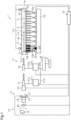
Fig. 1 is a schematic diagram showing an air-jet loom in accordance with a first embodiment. -
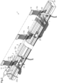
Fig. 2 is a perspective view showing the air-jet loom ofFig. 1 . -
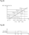
Fig. 3A is a timing chart showing opening and closing timings of a main valve and sub-valves in the air-jet loom ofFig. 1 . -
Fig. 3B is a timing chart showing opening and closing timings of an assist valve in the air-jet loom ofFig. 1 . -
Fig. 4 is a schematic diagram showing an air-jet loom in accordance with a second embodiment. -
Fig. 5A is a timing chart showing opening and closing timings of a main valve, sub-valves, and a stretch valve in the air-jet loom ofFig. 4 . -
Fig. 5B is a timing chart showing opening and closing timings of an assist valve in the air-jet loom ofFig. 4 . -
Fig. 6A is a timing chart showing opening and closing timings of a main valve and sub-valves in a modified example. -
Fig. 6B is a timing chart showing opening and closing timings of an assist valve in a modified example. - Throughout the drawings and the detailed description, the same reference numerals refer to the same elements. The drawings may not be to scale, and the relative size, proportions, and depiction of elements in the drawings may be exaggerated for clarity, illustration, and convenience.
- This description provides a comprehensive understanding of the methods, apparatuses, and/or systems described. Modifications and equivalents of the methods, apparatuses, and/or systems described are apparent to one of ordinary skill in the art. Sequences of operations are exemplary, and may be changed as apparent to one of ordinary skill in the art, with the exception of operations necessarily occurring in a certain order. Descriptions of functions and constructions that are well known to one of ordinary skill in the art may be omitted.
- Exemplary embodiments may have different forms, and are not limited to the examples described. However, the examples described are thorough and complete, and convey the full scope of the disclosure to one of ordinary skill in the art.
- In this specification, "at least one of A and B" should be understood to mean "only A, only B, or both A and B."
- A first embodiment of the present disclosure will now be described with reference to the drawings. In the description hereafter, the direction in which a weft Y flies when the weft Y is inserted into a warp shed is referred to as the weft insertion direction X.
- As shown in
Fig. 1 , an air-jet loom 1 includes aweft insertion device 10, one ormore assist nozzles 15b, a final positionarrival time sensor 40, a balloon sensor 19, astate detection sensor 45, a middle positionarrival time sensor 41, and acontroller 16. The air-jet loom 1 of the present embodiment includes multiple, specifically, three,assist nozzles 15b. The balloon sensor 19 corresponds to a weft detector in the present embodiment. - As shown in
Fig. 1 , theweft insertion device 10 includesweft insertion nozzles 11, ayarn feeder 12, a weft length measurement-storage device 13, areed 14, sub-nozzles 15a, abrake 23, and thecontroller 16. - The
yarn feeder 12 is located at the upstream side of theweft insertion nozzles 11 in the weft insertion direction X. The weft length measurement-storage device 13 includes a winding arm (not shown) that rotates to draw the weft Y from theyarn feeder 12 and wind the weft Y around a drum 17 for storage. Theweft insertion nozzles 11 include atandem nozzle 21, which withdraws the weft Y from the drum 17, and amain nozzle 22, which inserts the weft Y into an in-reed passage 14a of thereed 14. Thetandem nozzle 21, thebrake 23, the weft length measurement-storage device 13, and theyarn feeder 12 are fixed to, for example, a coupling member such as a frame (not shown) of the air-jet loom 1 or a bracket coupled to the floor surface. - As shown in
Fig. 2 , themain nozzle 22, the sub-nozzles 15a, the three assistnozzles 15b, and thereed 14 are arranged on asleigh 24.Fig. 2 shows one of the sub-nozzles 15a and one of the three assistnozzles 15b. Themain nozzle 22, the sub-nozzles 15a, the three assistnozzles 15b, and thereed 14 are moved back and forth integrally with thesleigh 24 in the forward and rearward directions of the air-jet loom 1. The sub-nozzles 15a and theassist nozzles 15b are each fixed by asupport block 25 to thesleigh 24. The sub-nozzles 15a and the three assistnozzles 15b are located within a weaving width TL (refer toFig. 1 ). As thesleigh 24 moves back and forth, the sub-nozzles 15a and theassist nozzles 15b moved into and out of a warp shed between layers of warps T within the weaving width TL. - The
reed 14 includesreed blades 14c, each having aguide recess 14b, arranged in the weft insertion direction X. The in-reed passage 14a extends through the guide recesses 14b of thereed blades 14c. - A cutting device (not shown) for cutting the weft Y is arranged between the
main nozzle 22 and the in-reed passage 14a. Thus, if anassist nozzle 15b were to be arranged outside the weaving width TL, for example, between themain nozzle 15b and the in-reed passage 14a, themain nozzle 22 would have to be distanced from the in-reed passage 14a to provide space for arrangement of the assist nozzle 15. If the distance between themain nozzle 22 and the in-reed passage 14a were to be increased, the amount of air consumed by themain nozzle 14 would have to be increased. In this respect, theassist nozzles 15b are arranged within the weaving width TL. Thus, themain nozzle 22 does not have to be distanced from the in-reed passage 14a. - As shown in
Fig. 1 , the weft length measurement-storage device 13 includes aweft holding pin 18. Theweft holding pin 18 is located near the drum 17. Theweft holding pin 18 is electrically connected to thecontroller 16. - The
weft insertion device 10 moves theweft holding pin 18 backward to unwind the weft Y, which is wound around the drum 17. More specifically, when the rotational angle of the air-jet loom 1 becomes a preset angle, theweft holding pin 18 moves backward and unwinds the weft Y from the drum 17. The time at which theweft holding pin 18 unwinds the weft Y is referred to as the weft insertion initiation time. - The
controller 16 then returns theweft holding pin 18 to the position where it was located prior to the unwinding of the weft Y. Theweft holding pin 18 engages the weft Y unwound from the drum 17 and ends the weft insertion. The time at which theweft holding pin 18 engages the weft Y is set in accordance with the number of windings required for the weft Y wound around and stored on the drum 17 to have the length corresponding to the weaving width TL. - The
brake 23 is located at the downstream side of the drum 17 in the weft insertion direction X. Thebrake 23 brakes the flying weft Y before the insertion of the weft Y ends. Thebrake 23 brakes the weft Y that flies at a high speed to lower the flying speed of the weft Y. This lowers the flying speed of the weft Y before theweft holding pin 18 engages the weft Y. Consequently, the impact on the weft Y is reduced when theweft holding pin 18 engages the weft Y. Theweft holding pin 18 engages the weft Y when the leading end of the weft Y reaches a final position Pw, which is the insertion terminal end. - The
main nozzle 22 is connected by apipe 22a to amain valve 22v. Themain valve 22v is connected by apipe 22b to amain air tank 26. Thetandem nozzle 21 is connected by apipe 21a to atandem valve 21v. Thetandem valve 21v is connected by apipe 21b to themain air tank 26, which is shared with themain valve 22v. Thetandem valve 21v may be connected to an air tank that is separate from themain air tank 26. Themain air tank 26 is connected to anair compressor 31, which is installed in a weaving factory. Themain air tank 26 is supplied with compressed air from theair compressor 31. - When the
main valve 22v is open, themain nozzle 22 emits compressed air. When themain valve 22v is closed, themain nozzle 22 does not emit air. The emission of compressed air from themain nozzle 22 is started and stopped by opening and closing themain valve 22v. When thetandem valve 21v is open, thetandem nozzle 21 emits compressed air. When thetandem valve 21v is closed, thetandem nozzle 21 does not emit air. The emission of compressed air from thetandem nozzle 21 is started and stopped by opening and closing thetandem valve 21v. - The sub-nozzles 15a and the three assist
nozzles 15b are arranged within the weaving width TL in the weft insertion direction X. InFig. 1 , for the sake of simplicity, the sub-nozzles 15a are represented by white boxes and theassist nozzles 15b are represented by black boxes. The sub-nozzles 15a are, for example, divided into nine nozzle groups. Each nozzle group includes two adjacent ones of the sub-nozzles 15a. In the description hereafter, the nine nozzle groups will be referred to, in order from the upstream side to the downstream side in the weft insertion direction X, as the first nozzle group, the second nozzle group, the third nozzle group, the fourth nozzle group, the fifth nozzle group, the sixth nozzle group, the seventh nozzle group, the eighth nozzle group, and the ninth nozzle group. The threeassist nozzles 15b include a first assist nozzle, a second assist nozzle, and a third assist nozzle. The first assist nozzle is located between the two sub-nozzles 15a of the first nozzle group. The second assist nozzle is located between the first nozzle group and the second nozzle group. The third assist nozzle is located between the two sub-nozzles 15a of the second nozzle group. - The assist nozzles 15b are located within the weaving width TL at the upstream side in the weft insertion direction X. The phrase of "within the weaving width TL at the upstream side in the weft insertion direction X" refers to region TLa that extends from the center TLc of the weaving width TL to the upstream weaving end Tle in the weft insertion direction X. In the present embodiment, the
assist nozzles 15b are arranged between the foursub-nozzles 15a that are located at the most upstream side in the weft insertion direction X. Thus, a repetitive pattern of one sub-nozzle 15a followed by oneassist nozzle 15b forms three sets of the sub-nozzle 15a and theassist nozzle 15b from the upstream side in the weft insertion direction X. The region at the downstream side of these sets in the weft insertion direction X includes all of the other sub-nozzles 15a. In the air-jet loom 1 of the present embodiment, theassist nozzles 15b are located within the weaving width TL only at the upstream side in the weft insertion direction X. - A sub-valve 32a is connected to each of the first to ninth nozzle groups. Thus, the
weft insertion device 10 includes nine sub-valves 32a. The threeassist nozzles 15b are connected to anassist valve 32b. Thus, theweft insertion device 10 includes oneassist valve 32b. InFig. 1 , for the sake of simplicity, the sub-valves 32a are represented by white boxes, and theassist valve 32b is represented by a black box. - In each of the first to ninth nozzle groups, the two sub-nozzles 15a are connected by corresponding sub-pipes 33a to the same sub-valve 32a. Thus, the
weft insertion device 10 includes eighteen sub-pipes 33a. The threeassist nozzles 15b are connected by correspondingassist pipes 33b to thesame assist valve 32b. Thus, theweft insertion device 10 includes three assistpipes 33b. The sub-valves 32a and theassist valve 32b are connected to the samesub-air tank 34. Theassist valve 32b may be connected to an air tank that is separate from thesub-air tank 34. - When each sub-valve 32a is open, the corresponding sub-nozzles 15a emit air. The sub-nozzles 15a emit air that applies a driving force to the weft Y in the weft insertion direction X. When each sub-valve 32a is closed, the corresponding sub-nozzles 15a do not emit air. The emission of air from each sub-nozzle 15a is started and stopped by opening and closing the corresponding sub-valve 32a.
- When the
assist valve 32b is open, theassist nozzles 15b emit air. The assist nozzles 15b emit air that applies a driving force to the weft Y in the weft insertion direction X. Thus, the air-jet loom 1 includes theassist nozzles 15b, which are separate from the sub-nozzles 15a, to emit air and apply a driving force to the weft Y in the weft insertion direction X. When theassist valve 32b is closed, theassist nozzles 15b do not emit air. The emission of air from each assistnozzle 15b is started and stopped by opening and closing theassist valve 32b. - The
main valve 22v, thetandem valve 21v, the sub-valves 32a, and the three assistvalves 32b are electrically connected to thecontroller 16. Thecontroller 16 controls and actuates themain valve 22v, the sub-valves 32a, and the three assistvalves 32b to emit air from themain nozzle 22, the sub-nozzles 15a, and the three assistnozzles 15b. Thus, thecontroller 16 controls the emission of air from themain nozzle 22, the sub-nozzles 15a, and the three assistnozzles 15b. - The emission of air from the
main nozzle 22 and the sub-nozzles 15a propels the weft Y through the in-reed passage 14a and inserts the weft Y into the warp shed. Theweft insertion device 10 performs a weft insertion operation that emits air from themain nozzle 22 and the sub-nozzles 15a, which propels the unwound weft Y through the in-reed passage 14a of thereed 14, and inserts the weft Y into the warp shed. Theweft insertion device 10 repetitively performs such a weft insertion operation. - More specifically, during insertion of the weft Y, the
controller 16 sends actuation signals to themain valve 22v and thetandem valve 21v. Further, during insertion of the weft Y, thecontroller 16 sends an actuation signal to each sub-valve 32a. As a result, the compressed air emitted from themain nozzle 22 acts to start propelling the weft Y, and the compressed air emitted from the sub-nozzles 15a propels the weft Y to the final position Pw. - The final position
arrival time sensor 40 is positioned to face a downstream region of the in-reed passage 14a in the weft insertion direction X. The final positionarrival time sensor 40 is located outside the weaving width TL. The final positionarrival time sensor 40 is arranged so that when the weft Y is in a correctly inserted state, the leading end of the weft Y, which has a length corresponding to an n number of windings around the drum 17, is located at the detection position of the final positionarrival time sensor 40. The final positionarrival time sensor 40 is electrically connected to thecontroller 16. The final positionarrival time sensor 40 outputs a weft detection signal when detecting the leading end of the weft Y. The weft detection signal indicates that the weft Y has reached the final position Pw. Based on the weft detection signal output by the final positionarrival time sensor 40, thecontroller 16 recognizes a final position arrival time Tw at which the leading end of the weft Y reaches the detection position of the final positionarrival time sensor 40. Thus, the final positionarrival time sensor 40 detects the final position arrival time Tw at which the leading end of the inserted weft Y reaches the final position Pw. The final positionarrival time sensor 40 outputs the weft detection signal to thecontroller 16 so that thecontroller 16 recognizes the final position arrival time Tw. - The balloon sensor 19 detects the weft Y unwound from the drum 17. Thus, the balloon sensor 19, which is a weft detector, detects information related to the flying motion of the weft Y before the weft Y reaches the final position Pw. The balloon sensor 19 is included in the weft length measurement-
storage device 13. The balloon sensor 19 is located near the drum 17. The balloon sensor 19 is electrically connected to thecontroller 16. - When detecting the weft Y unwound from the drum 17, the balloon sensor 19 sends a weft unwinding signal to the
controller 16. When receiving the weft unwinding signal for a preset n number of times, thecontroller 16 returns theweft holding pin 18 to the position where it was located prior to the unwinding of the weft Y. This engages theweft holding pin 18 with the weft Y unwound from the drum 17 and ends the weft insertion. - The
state detection sensor 45 detects the state of the weft Y supplied from theyarn feeder 12. Thestate detection sensor 45 is located between theyarn feeder 12 and the drum 17 in the weft insertion direction X. More specifically, thestate detection sensor 45 is located at the upstream side of the drum 17 in the weft insertion direction X. The weft Y is inserted into the warp shed downstream from the drum 17 in the weft insertion direction X. Thus, thestate detection sensor 45 detects the state of the weft Y prior to weft insertion. In other words, thestate detection sensor 45 detects information related to the flying motion of the weft Y before the weft Y reaches the final position Pw. - The state of the weft Y that the
state detection sensor 45 detects is a yarn parameter related to at least one of yarn mass, yarn diameter, yarn density, yarn surface structure, yarn fluffing, and yarn material. The state of the weft Y affects the propulsion of the weft Y when the weft Y flies during weft insertion. - The
state detection sensor 45 is electrically connected to thecontroller 16. When detecting the state of the weft Y prior to weft insertion, thestate detection sensor 45 sends a state detection signal to thecontroller 16. Based on the state detection signal, thecontroller 16 recognizes the state of the weft Y. - The middle position
arrival time sensor 41 is positioned at the upstream side of the final positionarrival time sensor 40 in the weft insertion direction X facing the in-reed passage 14a within the weaving width TL. In the present embodiment, the middle positionarrival time sensor 41 is located at the upstream side of the center TLc of the weaving width TL in the weft insertion direction X. The middle positionarrival time sensor 41 is arranged so that the detection position of the middle positionarrival time sensor 41 is where the leading end of the weft Y is located when the inserted weft Y is still shorter than the length corresponding to the n number of windings stored around the drum 17. Thus, the middle positionarrival time sensor 41 detects information related to the flying motion of the weft Y before the weft Y reaches the final position Pw. - The middle position
arrival time sensor 41 is electrically connected to thecontroller 16. When detecting the leading end of the weft Y, the middle positionarrival time sensor 41 outputs a weft detection signal. Based on the weft detection signal output by the middle positionarrival time sensor 41, thecontroller 16 recognizes a middle position arrival time Ti at which the leading end of the weft Y reaches the middle positionarrival time sensor 41. Thus, the middle positionarrival time sensor 41 detects the middle position arrival time Ti at which the leading end of the inserted weft Y reached a predetermined position Pi that is located at an upstream side of the final position Pw in the weft insertion direction X. - The
controller 16 includes a processor and storage. The processor is, for example, a central processing unit (CPU), a graphics processing unit (GPU), or a digital signal processor (DSP). The storage includes a random-access memory (RAM) and a read-only memory (ROM). The storage stores program codes or instructions configured to have the processor execute a process. The storage, or a computer readable medium, includes any type of medium that is accessible by a general-purpose computer or a dedicated computer. Thecontroller 16 may be configured by a hardware circuit such as an application specific integrated circuit (ASIC) or a field programmable gate array (FPGA). Thecontroller 16, which is processing circuitry, may be one or more processors running on computer programs, one or more hardware circuits such as ASICs, FPGAs, or the like, or a combination of these elements. - During each weft insertion operation, the
controller 16 executes relay control so that the sub-nozzles 15a sequentially emit air starting from those located at the upstream side in the weft insertion direction X. Thus, the sub-nozzles 15a are nozzles that emit air during the relay control. - In the relay control of the present embodiment, the
controller 16 emits air from the nozzle groups in the order of: the first nozzle group, the second nozzle group, the third nozzle group, the fourth nozzle group, the fifth nozzle group, the sixth nozzle group, the seventh nozzle group, the eighth nozzle group, and the ninth nozzle group. Thecontroller 16, for example, starts emitting air from themain nozzle 22 and starts emitting air from the two sub-nozzles 15a of the first nozzle group simultaneously. Thecontroller 16 may start emitting air from themain nozzle 22 and then start emitting air from the two sub-nozzles 15a of the first nozzle group. - In the present embodiment, the
controller 16 emits air from themain nozzle 22 and the sub-nozzles 15a based on the final position arrival time Tw acquired from the final positionarrival time sensor 40. For example, thecontroller 16 adjusts a propelling condition C so that the final position arrival time Tw, which is the detection result acquired from the final positionarrival time sensor 40, becomes close to a target value. - When, for example, the final position arrival time Tw detected by the final position
arrival time sensor 40 is later than the target time, thecontroller 16 sets the propelling condition C to increase the propelling speed of the weft Y so that the final position arrival time Tw will be advanced in the next weft insertion and be closer to the target time. When, for example, the final position arrival time Tw detected by the final positionarrival time sensor 40 is earlier than the target time, thecontroller 16 sets the propelling condition C to decrease the propelling speed of the weft Y so that the final position arrival time Tw will be delayed in the next weft insertion and be closer to the target time. - The storage of the
controller 16 stores multiple conditions that can be used as the propelling condition C. The timing at which air is emitted from themain nozzle 22 and the sub-nozzles 15a is different in each condition. These conditions differ from one another in the flying speed of the weft Y and are set in advance based on experiments and the like. Thecontroller 16 controls the emission of air from themain nozzle 22 and the sub-nozzles 15a in accordance with the propelling condition C. Thecontroller 16 sets the propelling condition C based on the final position arrival time Tw to optimize the final position arrival time Tw during the next insertion of the weft Y. - The valve open time of the
main nozzle 22 is predetermined and fixed to be the same in all of the propelling conditions C stored in the storage of thecontroller 16. The valve open time of the sub-nozzles 15a is predetermined and fixed to be the same time in all of the propelling conditions C stored in the storage of thecontroller 16. In at least one of the propelling conditions C stored in the storage of thecontroller 16, the valve open time of themain nozzle 22 may differ from that of the other propelling conditions C. In at least one of the propelling conditions C stored in the storage of thecontroller 16, the valve open time of the sub-nozzles 15a may differ from that of the other propelling conditions C. - In addition to the relay control, the
controller 16 is configured to execute assist control that emits air from one ormore assist nozzles 15b during weft insertion. In the assist control of the present embodiment, thecontroller 16 emits air from the three assistnozzles 15b. Thus, the three assistnozzles 15b are nozzles that emit air during the assist control. The assist control is executed to assist the weft insertion operation. The assist control of the present embodiment is executed to increase the flying speed of the weft Y when there is a delay in the flying motion of the weft Y during weft insertion. - In the present embodiment, the
controller 16 infers a delay in the flying motion of the weft Y based on the detection result acquired from the balloon sensor 19, which is a weft detector. More specifically, thecontroller 16 determines whether the time point at which the weft unwinding signal from the balloon sensor 19 is received a predetermined number of times is later than a predetermined time point. The predetermined number of times is set as the number of times required for the leading end of the weft Y to reach a predetermined position set at the upstream side of the final positionarrival time sensor 40 in the weft insertion direction X. In this case, the predetermined time point is set as the time point at which leading edge of the inserted weft Y reaches the predetermined position without a delay. Thus, thecontroller 16 infers whether there is a delay in the flying motion of the weft Y by determining whether the time point at which the weft unwinding signal from the balloon sensor 19 is received the predetermined number of times is later than the predetermined time point. Thecontroller 16 infers that the flying motion of the weft Y is delayed when the time point at which the weft unwinding signal from the balloon sensor 19 is received the predetermined number of times is later than the predetermined time point. - Based on the delay inference result, the
controller 16 determines whether to execute the assist control. Thecontroller 16 executes the assist control when inferring that there is a delay in the flying motion of the weft Y. More specifically, thecontroller 16 emits air from theassist nozzles 15b when inferring that there is a delay in the flying motion of the weft Y. Thecontroller 16 does not execute the assist control when inferring that there is no delay in the flying motion of the weft Y. More specifically, thecontroller 16 does not emit air from theassist nozzles 15b when inferring that there is no delay in the flying motion of the weft Y. Thus, when the weft insertion operation is performed in cycles, the relay control and the assist control are both executed in cycles in which the flying motion of the weft Y is delayed, and only the relay cycle is executed in cycles in which the flying motion of the weft Y is not delayed. - When the flying motion of the weft Y is delayed, the
controller 16 emits air from theassist nozzles 15b in addition to emitting air from themain nozzle 22 and the sub-nozzles 15a. The timing at which the assist control starts emitting air from theassist nozzles 15b may, for example, differ from the timing at which the relay control starts emitting air from themain nozzle 22 and the sub-nozzles 15a. - The operation of the above embodiment will now be described.
-
Fig. 3A is a timing chart of the relay control showing one example of the opening and closing timing of each of themain valve 22v and the sub-valves 32a, that is, the air emission timing of each of themain nozzle 22 and the sub-nozzles 15a.Fig. 3B is a timing chart of the assist control showing one example of the opening and closing timing of theassist valve 32b, that is, the air emission timing of the three assistnozzles 15b.Figs. 3A and Fig. 3B show the air emission timing of themain nozzle 22, the sub-nozzles 15a, and the three assistnozzles 15b during a single weft insertion operation. - In
Fig. 3A , line M indicates air emission of themain nozzle 22. Lines E1, E2, E3, and E4 respectively indicate air emission of the first nozzle group, the second nozzle group, the third nozzle group, and the fourth nozzle group.Fig. 3A does not show the air emission of the fifth to ninth nozzle groups. - Time T1 is when the
weft holding pin 18 moves backward to start unwinding the weft Y from the drum 17. Time M1 is when themain nozzle 22 starts emitting air. Times E2s, E3s, and E4s are when the sub-nozzles 15a of the second nozzle group, the third nozzle group, and the fourth nozzle group start emitting air. Time M2 is when themain nozzle 22 stops emitting air. Times E1e, E2e, and E3e are when the sub-nozzles 15a of the first nozzle group, the second nozzle group, and the third nozzle group stop emitting air. The time at which the sub-nozzles 15a of the fourth nozzle group stop emitting air is not shown. Line D1 indicate one example of the flying motion of the weft Y. - Referring to
Fig. 3B , time T2 is when thecontroller 16 determines whether the time point at which the weft unwinding signal from the balloon sensor 19 received by thecontroller 16 the predetermined number of times is later than the predetermined time point. Thus, time T2 is when thecontroller 16 infers whether there is a delay in the flying motion of the weft Y based on the detection result acquired from the balloon sensor 19, which is the weft detector. At time T2, when the time point at which the weft unwinding signal from the balloon sensor 19 is received the predetermined number of times is later than the predetermined time point, thecontroller 16 infers that there is a delay in the flying motion of the weft Y. When inferring that there is a delay in the flying motion of the weft Y, thecontroller 16 executes assist control and emits air from theassist nozzles 15b. Time T3 is when theassist valve 32b opens; that is, when the three assistnozzles 15b start emitting air. Time T4 is when theassist valve 32b closes, that is, when the three assistnozzles 15b stop emitting air. - The
controller 16 is configured to execute assist control that emits air from theassist nozzles 15b in addition to the relay control during each weft insertion operation. In the present embodiment, thecontroller 16 executes the assist control when inferring that the flying motion of the weft Y is delayed. More specifically, when the flying motion of the weft Y is delayed, thecontroller 16 emits air from the three assistnozzles 15b through the assist control in addition to emitting air from themain nozzle 22 and the sub-nozzles 15a through the relay control. Thus, compared with when only the relay control is executed and the assist control is not executed, the air emitted from the three assistnozzles 15b when the relay control and the assist control are executed acts on the weft Y so that the weft Y flies at a higher speed. - The above embodiment has the advantages described below.
- (1-1) The air-jet loom 1 includes the one or
more assist nozzles 15b, which are separate from the sub-nozzles 15a, within the weaving width TL to emit air that applies a driving force to the weft Y in the weft insertion direction X. Thecontroller 16 controls the emission of air from the one ormore assist nozzles 15b. In addition to the relay control, thecontroller 16 is configured to execute assist control that emits air from the one ormore assist nozzles 15b during weft insertion. - This configuration emits air from the one or
more assist nozzles 15b, which are separate from the sub-nozzles 15a that emit air during the relay control. As a result, the weft insertion operation is assisted without lengthening the air emission time of the sub-nozzles 15a or increasing frequency of air emission from the sub-nozzles 15a. - (1-2) The
controller 16 infers whether there is a delay in the flying motion of the weft Y based on the detection result acquired from the balloon sensor 19, which is the weft detector. Thecontroller 16 executes the assist control when inferring that there is a delay in the flying motion of the weft Y. With this configuration, when thecontroller 16 infers that there is a delay in the flying motion of the weft Y, air is emitted from theassist nozzles 15b. Thus, when there is a delay in the flying motion of the weft Y, air is emitted from theassist nozzles 15b to increase the flying speed of the weft Y. This assists the weft insertion operation without lengthening the air emission time of the sub-nozzles 15a or increasing frequency of air emission from the sub-nozzles 15a. - (1-3) The weft detector is the balloon sensor 19 that detects the weft Y unwound from the drum 17. Thus, the
controller 16 can infer whether there is a delay in the flying motion of the weft Y from the detection result of the balloon sensor 19 used to propel the weft Y. This allows thecontroller 16 to infer whether there is a delay in the flying motion of the weft Y without increasing components. - (1-4) The assist nozzles 15b are located within the weaving width TL at the upstream side in the weft insertion direction X. In comparison with when air is emitted from the
assist nozzles 15b within the weaving width TL at the downstream side in the weft insertion direction X, the range over which air acts on the weft Y is greater and the flying speed of the weft Y increased by theassist nozzles 15b is higher when air is emitted from theassist nozzles 15b within the weaving width TL at the upstream side in the weft insertion direction X. - (1-5) In the air-jet loom 1, the
assist nozzles 15b are located within the weaving width TL only at the upstream side in the weft insertion direction X. In the air-jet loom 1, the weaving width TL is changed at the downstream side in the weft insertion direction X using the upstream side in the weft insertion direction X as a reference. When changing the weaving width TL, if theassist nozzles 15b are located within the weaving width TL at the downstream side in the weft insertion direction X, the positions of theassist nozzles 15b will have to be adjusted in accordance with the weaving width TL. In this respect, theassist nozzles 15b in the present embodiment are located within the weaving width TL only at the upstream side in the weft insertion direction X. Thus, the positions of theassist nozzles 15b do not have to be adjusted when the weaving width TL is changed. - A second embodiment of the present disclosure will now be described with reference to the drawings. Elements of the air-jet loom 1 that have been described in the first embodiment will not be described below.
- As shown in
Fig. 4 , the air-jet loom 1 includes atensioner 50 that applies tension to the weft Y. Thetensioner 50 includes astretch nozzle 51. Thestretch nozzle 51 is located at the downstream side of the final position Pw in the weft insertion direction X. Thestretch nozzle 51 is located at the downstream side of the final positionarrival time sensor 40 in the weft insertion direction X. Thestretch nozzle 51 is arranged on thesleigh 24. Thestretch nozzle 51 is moved back and forth integrally with thesleigh 24 in the forward and rearward directions of the air-jet loom 1. - The
stretch nozzle 51 is connected to astretch valve 52 by astretch pipe 53. Thestretch valve 52 is connected to astretch air tank 54. When thestretch valve 52 is open, thestretch nozzle 51 emits air. When thestretch valve 52 is closed, thestretch nozzle 51 does not emit air. The emission of air from thestretch nozzle 51 is started and stopped by opening and closing thestretch valve 52. - The
stretch valve 52 is electrically connected to thecontroller 16. Thecontroller 16 controls and actuates thestretch valve 52 to emit air from thestretch nozzle 51. Thus, thecontroller 16 controls the emission of air from thestretch nozzle 51. Thecontroller 16 emits air from thestretch nozzle 51 after the leading end of the weft Y reaches the final position Pw. Thecontroller 16, for example, starts emitting air from thestretch nozzle 51 before the leading end of the weft Y reaches a position corresponding to thestretch nozzle 51 in the weft insertion direction X. - After the leading end of the weft Y reaches the final position Pw, the
stretch nozzle 51 emits air toward the part of the weft Y located at the downstream side in the weft insertion direction X. The air emitted from thestretch nozzle 51 stretches the downstream part of the weft Y in the weft insertion direction X and reduces slack of the weft Y. - The
controller 16 executes relay control during each weft insertion operation. The relay control is executed in the same manner as the first embodiment and thus will not be described. Thecontroller 16 executes assist control that emits air from theassist nozzles 15b in addition to the relay control during each weft insertion operation. Thus, theassist nozzles 15b are nozzles that emit air during the assist control. The assist control is executed to assist the weft insertion operation. The assist control in the present embodiment is executed after the weft Y reaches the final position Pw to reduce slack of the weft Y at the upstream side in the weft insertion direction X. - In the present embodiment, the
assist nozzles 15b are located within the weaving width TL at the upstream side in the weft insertion direction X. In the present embodiment, thecontroller 16 executes the assist control after the weft Y reaches the final position Pw. More specifically, thecontroller 16 emits air from theassist nozzles 15b after the weft Y reaches the final position Pw. Thus, after the leading end of the weft Y reaches the final position Pw, theassist nozzles 15b emit air toward the upstream part of the weft Y in the weft insertion direction X. - The operation of the above embodiment will now be described.
- In
Fig. 5A , lines E5, E6, E7, E8, and E9 respectively indicate air emission of the fifth nozzle group, the sixth nozzle group, the seventh nozzle group, the eighth nozzle group, and the ninth nozzle group. Time E9e is when the ninth nozzle group stops emitting air. Line S indicates air emission of thestretch nozzle 51. Time Ss is when thestretch valve 52 opens, that is, when thestretch nozzle 51 starts emitting air. -
Fig. 5B is a timing chart showing the air emission timing of the three assistnozzles 15b. As described above, time T3 is when the three assistnozzles 15b start emitting air. In the present embodiment, time T3 coincides with time Ss. More specifically, thestretch nozzle 51 starts emitting air and the three assistnozzles 15b start emitting air simultaneously. Time T4 is when the three assistnozzles 15b stop emitting air. In the present embodiment, time T4 coincides with time E9e. More specifically, the two sub-nozzles 15a of the ninth nozzle group, which is located within the weaving width TL at the most downstream side in the weft insertion direction X, stop emitting air and the three assistnozzles 15b stop emitting air simultaneously. - The
controller 16 executes assist control, which emits air from the three assistnozzles 15b, in addition to relay control during each weft insertion operation. Thecontroller 16 of the present embodiment executes assist control after the leading end of the weft Y reaches the final position Pw. Thus, after the leading end of the weft Y reaches the final position Pw, the three assistnozzles 15b emit air that stretches the weft Y in the weft insertion direction X and reduces slack of the weft Y. - In addition to advantages (1-1) and (1-5) of the first embodiment, the above embodiment has the advantages described below.
- (2-1) The assist nozzles 15b are located within the weaving width TL at the upstream side in the weft insertion direction X. The
controller 16 executes assist control after the leading end of the weft Y reaches the final position Pw. With this configuration, theassist nozzles 15b emit air after the leading end of the weft Y reaches the final position Pw. Thus, after the leading end of the weft Y reaches the final position Pw, theassist nozzles 15b emit air to stretch the weft Y in the weft insertion direction X and reduce slack of the weft Y. This allows slack of the weft Y to be reduced without lengthening the air emission time of the sub-nozzles 15a or increasing the frequency of air emission from the sub-nozzles 15a. - Further, the
assist nozzles 15b are located within the weaving width TL at the upstream side in the weft insertion direction X. This allows theassist nozzles 15b to emit air toward the part of the weft Y that may become loose, that is, the part located within the weaving width TL at the upstream side in the weft insertion direction X. Thus, slack of the weft Y is reduced effectively. - (2-2) The air-jet loom 1 includes the
tensioner 50. Thetensioner 50 includes thestretch nozzle 51 that is arranged at the downstream side of the final position Pw in the weft insertion direction X and emits air toward the weft Y. Thecontroller 16 controls the emission of air from thestretch nozzle 51. Thecontroller 16 starts emitting air from thestretch nozzle 51 and starts emitting air from theassist nozzles 15b simultaneously. - With this configuration, the air emitted from the
assist nozzles 15b and the air emitted from thestretch nozzle 51 both stretch the weft Y simultaneously. This further reduces slack of the weft Y. The time at which theassist nozzles 15b start emitting air is matched with that of another nozzle. This facilitates control of the timing for starting air emission. - (2-3) The
controller 16 stops emitting air from the sub-nozzles 15a that are located within the weaving width TL at the most downstream side in the weft insertion direction X and stops emitting air from theassist nozzles 15b simultaneously. - This configuration lessens damages that may be inflicted to the weft Y in comparison with when the sub-nozzles 15a located within the weaving width TL at the most downstream side in the weft insertion direction X stops emitting air as the
assist nozzles 15b continue to emit air afterwards. Further, the time at which theassist nozzles 15b stop emitting air is matched with that of another nozzle. This facilitates control of the timing for stopping air emission. - (2-4) To reduce slack of the weft Y, the air emission time of one or more sub-nozzles 15a located within the weaving width TL at the upstream side in the weft insertion direction X may be lengthened. In this case, however, the one or more sub-nozzles 15a located within the weaving width TL at the upstream side in the weft insertion direction X will have to continuously emit air from immediately after weft insertion starts to after the leading end of the weft Y reaches the final position Pw. This increases the amount of air emitted from the one or more sub-nozzles 15a located within the weaving width TL at the upstream side in the weft insertion direction X. In this respect, in the present embodiment, the sub-nozzles 15a located within the weaving width TL at the upstream side in the weft insertion direction X emits air only immediately after weft insertion. This decreases the amount of air emitted from the sub-nozzles 15a located within the weaving width TL at the upstream side in the weft insertion direction X.
- The above embodiments may be modified as described below. The above embodiments and the following modified example can be combined as long as there is no technical contradiction.
- In the first embodiment, the
controller 16 may infer whether there is a delay in the flying motion of the weft Y based on the detection result acquired from the middle positionarrival time sensor 41. In this case, the middle positionarrival time sensor 41 corresponds to a weft detector that detects information related to the flying motion of the weft Y before the weft Y reaches the final position Pw. In this modified example, in the same manner as the example illustrated inFigs. 3A and 3B , air is emitted from each of themain nozzle 22, the sub-nozzles 15a, and the one ormore assist nozzles 15b. In this modified example, at time T2 shown inFig. 3B , thecontroller 16 infers whether there is a delay in the flying motion of the weft Y based on the detection result acquired from the middle positionarrival time sensor 41, which is the weft detector. When thecontroller 16 infers that there is a delay in the flying motion of the weft Y at time T2, thecontroller 16 executes assist control that emits air from theassist nozzles 15b. - In addition to advantages (1-1), (1-2), (1-4), and (1-5) of the first embodiment, the above modified example has the advantage described below.
- The weft detector is the middle position
arrival time sensor 41 that detects the middle position arrival time Ti at which the leading end of the inserted weft Y reaches the predetermined position Pi located at the upstream side of the final position Pw in the weft insertion direction X. The middle positionarrival time sensor 41, which detects the leading end of the inserted weft Y, allows the position of the weft Y in the weft insertion direction X to be detected with further accuracy. Thus, thecontroller 16 can infer a delay in the flying motion of the weft Y with higher accuracy. - In the above modified example, the
state detection sensor 45 may be omitted from the air-jet loom 1. - In the first embodiment, the
controller 16 may infer whether there is a delay in the flying motion of the weft Y based on the detection result acquired from thestate detection sensor 45. In this case, thestate detection sensor 45 corresponds to a weft detector that detects information related to the flying motion of the weft Y before the weft Y reaches the final position Pw. In this modified example, as illustrated inFigs. 6A and 6B , air is emitted from each of themain nozzle 22, the sub-nozzles 15a, and the more ormore assist nozzles 15b. The example illustrated inFigs. 6A and 6B differs from the example illustrated inFigs. 3A and Fig. 3B in the air emission timing of theassist nozzles 15b. In this modified example, at time T2 shown inFig. 6B , thecontroller 16 infers whether there is a delay in the flying motion of the weft Y based on the detection result acquired from thestate detection sensor 45, which is the weft detector. When thecontroller 16 infers at time T2 that there is a delay in the flying motion of the weft Y, thecontroller 16 executes assist control that emits air from theassist nozzles 15b. More specifically, thecontroller 16 emits air from theassist nozzles 15b when a delay in the flying motion of the weft Y can be expected. - In addition to advantages (1-1), (1-2), (1-4), and (1-5) of the first embodiment, the above modified example has the advantage described below.
- The weft detector is the
state detection sensor 45 that detects the state of the weft prior to weft insertion. The flying speed of the inserted weft Y varies in accordance with the state of the weft Y. A delay in the state of the weft Y may be inferred from the state of the weft Y. Thus, thecontroller 16 can infer a delay in the flying motion of the weft Y with higher accuracy. - In the above modified example, the middle position
arrival time sensor 41 may be omitted from the air-jet loom 1. - At least one of the
state detection sensor 45 and the middle positionarrival time sensor 41 may be omitted from the air-jet loom 1 in the above embodiments. - The middle position
arrival time sensor 41 may be located at a position corresponding to the center TLc of the weaving width TL or at a position located at the downstream side of the center TLc of the weaving width TL in the weft insertion direction X. - In the first embodiment, the positions of the
assist nozzles 15b may be changed. For example, theassist nozzles 15b may be located within the weaving width TL at the downstream side in the weft insertion direction X or be located within the weaving width TL at the center TLc in the weft insertion direction X. The phrase of "within the weaving width TL at the downstream side in the weft insertion direction X" refers to a region that extends from the center TLc of the weaving width TL to the downstream weaving end in the weft insertion direction X. The assist nozzles 15b may be located at two or more of the upstream side, the center TLc, and the downstream side within the weaving width TL in the weft insertion direction X. - In each of the above embodiments, the quantity of the sub-nozzles 15a in the
weft insertion device 10 may be changed as long as there are two or more. The quantity of theassist nozzles 15b in theweft insertion device 10 may be changed. The quantity of the groups of sub-nozzles 15a in theweft insertion device 10 may be changed. The quantity of the sub-nozzles 15a included in each group may be changed. When theweft insertion device 10 includes theassist nozzles 15b, theassist nozzles 15b may be divided into groups. In this case, each group may include any quantity of theassist nozzles 15b. The quantity of the sub-valves 32a may be changed in accordance with the quantity of the sub-nozzles 15a. The quantity ofassist valves 32b may be changed in accordance with the quantity of theassist nozzles 15b. - In the second embodiment, the
controller 16 does not have to start emitting air from thestretch nozzle 51 and theassist nozzles 15b simultaneously. The assist nozzles 15b may start emitting air at the same time as when another nozzle starts or stops emitting air. Alternatively, theassist nozzles 15b may start emitting air at a time that differs from when another nozzle starts or stops emitting air. - In the second embodiment, the
controller 16 does not have to stop emitting air from theassist nozzles 15b simultaneously with when stopping the emission of air from the sub-nozzles 15a located within the weaving width TL at the most downstream side in the weft insertion direction X. The assist nozzles 15b may stop emitting air at the same time as when another nozzle starts or stops emitting air. Alternatively, theassist nozzle 15b may stop emitting air at a time that differs from when another nozzle starts or stops emitting air. For example, thecontroller 16 may stop emitting air from theassist nozzles 15b at the same time as when stopping emitting air from thestretch nozzle 51. - During each weft insertion operation, in addition to the relay control, the
controller 16 may execute the assist control that increases the flying speed of the weft Y together with the assist control that reduces slack of the weft Y. When inferring that there is a delay in the flying motion of the weft Y, thecontroller 16 executes the assist control that increases the flying speed of the weft Y and the assist control that reduces slack of the weft Y. When inferring that there is no delay in the flying motion of the weft Y or that a delay cannot be expected, thecontroller 16 executes the relay control and the assist control that reduces slack of the weft Y, but does not execute the assist control that increases the flying speed of the weft Y. In this case, the one ormore assist nozzles 15b emitting air during the assist control that increases the speed of the flying weft Y may be the same as or differ from the one ormore assist nozzles 15b emitting air during the assist control that reduces slack of the weft Y
Claims (10)
- An air-jet loom (1), characterized by:a weft insertion device (10) configured to unwind a weft (Y) wound around a drum (17) by moving a weft holding pin (18) backward and configured to repeatedly perform a weft insertion operation that emits air from a main nozzle (22) and sub-nozzles (15a) to propel the unwound weft (Y) through an in-reed passage (14a) and insert the unwound weft (Y) into a warp shed; anda controller (16) configured to control the emission of air from the main nozzle (22) and the sub-nozzles (15a), whereinthe weft (Y) flies when propelled and inserted into the warp shed in a direction referred to as a weft insertion direction (X) in which the sub-nozzles (15a) are arranged next to each other,the controller (16) is configured to execute relay control during each weft insertion operation so that the sub-nozzles (15a) emit air sequentially starting from those located at an upstream side in the weft insertion direction (X),one or more assist nozzles (15b), separate from the sub-nozzles (15a), are arranged within a weaving width (TL) and are configured to emit air that applies a driving force to the weft (Y) in the weft insertion direction (X), the emission of air from the one or more assist nozzles (15b) being controlled by the controller (16), andthe controller (16) is configured to allow for execution of assist control that emits air from the one or more assist nozzles (16) in addition to the execution of the relay control during each weft insertion operation.
- The air-jet loom (1) according to claim 1, further characterized by:a weft detector configured to detect information related to a flying motion of the weft (Y) before the weft (Y) reaches a final position (Pw),wherein the controller (16) is configured to infer whether there is a delay in the flying motion of the weft (Y) based on a detection result acquired from the weft detector, and the controller (16) is configured to execute the assist control when inferring that there is a delay in the flying motion.
- The air-jet loom (1) according to claim 2, characterized in that the weft detector is a balloon sensor (19) that detects the weft (Y) unwound from the drum (17).
- The air-jet loom (1) according to claim 2, characterized in that the weft detector is a state detection sensor (45) that detects a state of the weft (Y) before each weft insertion operation.
- The air-jet loom (1) according to claim 2, characterized in that the weft detector is a middle position arrival time sensor (41) that detects a middle position arrival time (Ti) at which a leading end of the inserted weft (Y) reaches a predetermined position (Pi) located at an upstream side of the final position (Pw) in the weft insertion direction (X).
- The air-jet loom (1) according to any one of claims 2 to 5, characterized in that the one or more assist nozzles (15b) are located at an upstream side of the weaving width (TL) in the weft insertion direction (X).
- The air-jet loom (1) according to claim 6, characterized in that the one or more assist nozzles (15b) are located only at the upstream side of the weaving width (TL) in the weft insertion direction (X).
- The air-jet loom (1) according to claim 1, further characterized in that:the one or more assist nozzles (15b) are located at an upstream side of the weaving width (TL) in the weft insertion direction (X); andthe controller (16) is configured to execute the assist control after the leading end of the weft (Y) reaches a final position (Pw).
- The air-jet loom (1) according to claim 8, further characterized by:a tensioner (50) including a stretch nozzle (51) arranged at a downstream side of the final position (Pw) in the weft insertion direction (X) and configured to emit air toward the weft (Y), the emission of air from the stretch nozzle (51) being controlled by the controller (16), andthe controller (16) being configured to start emitting air from the stretch nozzle (51) and start emitting air from the one or more assist nozzles (15b) simultaneously.
- The air-jet loom (1) according to claim 8 or 9, characterized in that the controller (16) is configured to stop emitting air from one of the sub-nozzles (15a) that is located at a most downstream side of the weaving width (TL) in the weft insertion direction (X) and stop emitting air from the one or more assist nozzles (15b) simultaneously.
Applications Claiming Priority (2)
| Application Number | Priority Date | Filing Date | Title |
|---|---|---|---|
| JP2023187790 | 2023-11-01 | ||
| JP2024111688A JP2025076270A (en) | 2023-11-01 | 2024-07-11 | Air Jet Loom |
Publications (1)
| Publication Number | Publication Date |
|---|---|
| EP4549641A1 true EP4549641A1 (en) | 2025-05-07 |
Family
ID=93150200
Family Applications (1)
| Application Number | Title | Priority Date | Filing Date |
|---|---|---|---|
| EP24206586.0A Pending EP4549641A1 (en) | 2023-11-01 | 2024-10-15 | Air-jet loom |
Country Status (2)
| Country | Link |
|---|---|
| EP (1) | EP4549641A1 (en) |
| CN (1) | CN119932793A (en) |
Citations (6)
| Publication number | Priority date | Publication date | Assignee | Title |
|---|---|---|---|---|
| US4532964A (en) * | 1982-12-24 | 1985-08-06 | Gebruder Sulzer Aktiengesellschaft | Method of operating an air nozzle weaving machine |
| US4759392A (en) * | 1986-03-20 | 1988-07-26 | Picanol N.V. | Method and apparatus for the control of auxiliary nozzles for inserting weft threads in weaving looms |
| JPH06108345A (en) | 1992-05-21 | 1994-04-19 | Lindauer Dornier Gmbh | Method of pneumatically inserting weft in air nozzle loom |
| JP2014500914A (en) | 2010-11-25 | 2014-01-16 | ウステル・テヒノロジーズ・アクチエンゲゼルシヤフト | Method and apparatus for controlling a jet loom |
| JP2016172937A (en) * | 2015-03-17 | 2016-09-29 | 株式会社豊田自動織機 | Weft insertion control method in air-jet machine and weft insertion device in air-jet machine |
| EP4019678A1 (en) * | 2020-12-08 | 2022-06-29 | Kabushiki Kaisha Toyota Jidoshokki | Air-jet loom with weft-insertion control apparatus |
-
2024
- 2024-10-15 EP EP24206586.0A patent/EP4549641A1/en active Pending
- 2024-10-30 CN CN202411527627.2A patent/CN119932793A/en active Pending
Patent Citations (6)
| Publication number | Priority date | Publication date | Assignee | Title |
|---|---|---|---|---|
| US4532964A (en) * | 1982-12-24 | 1985-08-06 | Gebruder Sulzer Aktiengesellschaft | Method of operating an air nozzle weaving machine |
| US4759392A (en) * | 1986-03-20 | 1988-07-26 | Picanol N.V. | Method and apparatus for the control of auxiliary nozzles for inserting weft threads in weaving looms |
| JPH06108345A (en) | 1992-05-21 | 1994-04-19 | Lindauer Dornier Gmbh | Method of pneumatically inserting weft in air nozzle loom |
| JP2014500914A (en) | 2010-11-25 | 2014-01-16 | ウステル・テヒノロジーズ・アクチエンゲゼルシヤフト | Method and apparatus for controlling a jet loom |
| JP2016172937A (en) * | 2015-03-17 | 2016-09-29 | 株式会社豊田自動織機 | Weft insertion control method in air-jet machine and weft insertion device in air-jet machine |
| EP4019678A1 (en) * | 2020-12-08 | 2022-06-29 | Kabushiki Kaisha Toyota Jidoshokki | Air-jet loom with weft-insertion control apparatus |
Also Published As
| Publication number | Publication date |
|---|---|
| CN119932793A (en) | 2025-05-06 |
Similar Documents
| Publication | Publication Date | Title |
|---|---|---|
| EP3156529B1 (en) | Air jet loom with weft insertion control device | |
| EP3144422B1 (en) | Method for monitoring weft traveling condition in air jet loom | |
| EP3404132B1 (en) | Weft detecting device for air-jet loom | |
| CN104630976A (en) | Air-jet loom with weft yarn detector | |
| JP2008190108A (en) | Method and apparatus for insertion of weft thread in weaving machine | |
| EP3323920B1 (en) | Weft traveling condition detection apparatus in air jet loom | |
| JP7415904B2 (en) | Air jet loom weft insertion control device | |
| US4532964A (en) | Method of operating an air nozzle weaving machine | |
| JP2025076270A (en) | Air Jet Loom | |
| CN108350627B (en) | Method for inserting weft threads | |
| CN101198733B (en) | Method for introducing weft threads | |
| CN119932793A (en) | Air jet loom | |
| JP6994377B2 (en) | Weaving diagnostic method for air jet looms | |
| EP3819413B1 (en) | Air jet loom | |
| JP6787141B2 (en) | Weaving diagnostic method for air jet looms and weft diagnostic device for air jet looms | |
| JP2003221747A (en) | Control method for electric lug assembly device of fluid jet loom | |
| JP2879924B2 (en) | Jet loom weft insertion method and control device | |
| EP4474546A1 (en) | Information display device of air jet loom | |
| JP3355111B2 (en) | Weft insertion device for fluid jet loom | |
| JP2006063498A (en) | Control method of weft brake device and weft brake device | |
| CN101603233A (en) | The method of operating of the weft yarn withdrawing device in the control fluid jet type weaving machine | |
| JPH0734353A (en) | Jet loom | |
| JPH0734352A (en) | Jet loom | |
| JPH01192850A (en) | Weft-inserting method in shuttle-free weaving machine | |
| JP2001234450A (en) | Weft insertion method and apparatus for fluid jet loom |
Legal Events
| Date | Code | Title | Description |
|---|---|---|---|
| PUAI | Public reference made under article 153(3) epc to a published international application that has entered the european phase |
Free format text: ORIGINAL CODE: 0009012 |
|
| STAA | Information on the status of an ep patent application or granted ep patent |
Free format text: STATUS: REQUEST FOR EXAMINATION WAS MADE |
|
| 17P | Request for examination filed |
Effective date: 20241015 |
|
| AK | Designated contracting states |
Kind code of ref document: A1 Designated state(s): AL AT BE BG CH CY CZ DE DK EE ES FI FR GB GR HR HU IE IS IT LI LT LU LV MC ME MK MT NL NO PL PT RO RS SE SI SK SM TR |
|
| RIC1 | Information provided on ipc code assigned before grant |
Ipc: D03D 47/30 20060101AFI20251204BHEP Ipc: D03D 47/36 20060101ALI20251204BHEP |
|
| GRAP | Despatch of communication of intention to grant a patent |
Free format text: ORIGINAL CODE: EPIDOSNIGR1 |
|
| STAA | Information on the status of an ep patent application or granted ep patent |
Free format text: STATUS: GRANT OF PATENT IS INTENDED |
|
| INTG | Intention to grant announced |
Effective date: 20260205 |
|
| GRAS | Grant fee paid |
Free format text: ORIGINAL CODE: EPIDOSNIGR3 |
|
| GRAA | (expected) grant |
Free format text: ORIGINAL CODE: 0009210 |
|
| STAA | Information on the status of an ep patent application or granted ep patent |
Free format text: STATUS: THE PATENT HAS BEEN GRANTED |