EP4549624A1 - System and method for alternately performing urea electrolysis-based hydrogen production and carbon reduction, and application system - Google Patents
System and method for alternately performing urea electrolysis-based hydrogen production and carbon reduction, and application system Download PDFInfo
- Publication number
- EP4549624A1 EP4549624A1 EP23829893.9A EP23829893A EP4549624A1 EP 4549624 A1 EP4549624 A1 EP 4549624A1 EP 23829893 A EP23829893 A EP 23829893A EP 4549624 A1 EP4549624 A1 EP 4549624A1
- Authority
- EP
- European Patent Office
- Prior art keywords
- electrode
- carbon dioxide
- outlet
- urea
- electrode chamber
- Prior art date
- Legal status (The legal status is an assumption and is not a legal conclusion. Google has not performed a legal analysis and makes no representation as to the accuracy of the status listed.)
- Pending
Links
Images

Classifications
-
- C—CHEMISTRY; METALLURGY
- C25—ELECTROLYTIC OR ELECTROPHORETIC PROCESSES; APPARATUS THEREFOR
- C25B—ELECTROLYTIC OR ELECTROPHORETIC PROCESSES FOR THE PRODUCTION OF COMPOUNDS OR NON-METALS; APPARATUS THEREFOR
- C25B1/00—Electrolytic production of inorganic compounds or non-metals
- C25B1/01—Products
- C25B1/02—Hydrogen or oxygen
- C25B1/04—Hydrogen or oxygen by electrolysis of water
-
- C—CHEMISTRY; METALLURGY
- C25—ELECTROLYTIC OR ELECTROPHORETIC PROCESSES; APPARATUS THEREFOR
- C25B—ELECTROLYTIC OR ELECTROPHORETIC PROCESSES FOR THE PRODUCTION OF COMPOUNDS OR NON-METALS; APPARATUS THEREFOR
- C25B1/00—Electrolytic production of inorganic compounds or non-metals
- C25B1/01—Products
-
- C—CHEMISTRY; METALLURGY
- C25—ELECTROLYTIC OR ELECTROPHORETIC PROCESSES; APPARATUS THEREFOR
- C25B—ELECTROLYTIC OR ELECTROPHORETIC PROCESSES FOR THE PRODUCTION OF COMPOUNDS OR NON-METALS; APPARATUS THEREFOR
- C25B11/00—Electrodes; Manufacture thereof not otherwise provided for
- C25B11/04—Electrodes; Manufacture thereof not otherwise provided for characterised by the material
- C25B11/051—Electrodes formed of electrocatalysts on a substrate or carrier
- C25B11/052—Electrodes comprising one or more electrocatalytic coatings on a substrate
-
- C—CHEMISTRY; METALLURGY
- C25—ELECTROLYTIC OR ELECTROPHORETIC PROCESSES; APPARATUS THEREFOR
- C25B—ELECTROLYTIC OR ELECTROPHORETIC PROCESSES FOR THE PRODUCTION OF COMPOUNDS OR NON-METALS; APPARATUS THEREFOR
- C25B11/00—Electrodes; Manufacture thereof not otherwise provided for
- C25B11/04—Electrodes; Manufacture thereof not otherwise provided for characterised by the material
- C25B11/051—Electrodes formed of electrocatalysts on a substrate or carrier
- C25B11/073—Electrodes formed of electrocatalysts on a substrate or carrier characterised by the electrocatalyst material
- C25B11/091—Electrodes formed of electrocatalysts on a substrate or carrier characterised by the electrocatalyst material consisting of at least one catalytic element and at least one catalytic compound; consisting of two or more catalytic elements or catalytic compounds
-
- C—CHEMISTRY; METALLURGY
- C25—ELECTROLYTIC OR ELECTROPHORETIC PROCESSES; APPARATUS THEREFOR
- C25B—ELECTROLYTIC OR ELECTROPHORETIC PROCESSES FOR THE PRODUCTION OF COMPOUNDS OR NON-METALS; APPARATUS THEREFOR
- C25B3/00—Electrolytic production of organic compounds
- C25B3/01—Products
- C25B3/07—Oxygen containing compounds
-
- C—CHEMISTRY; METALLURGY
- C25—ELECTROLYTIC OR ELECTROPHORETIC PROCESSES; APPARATUS THEREFOR
- C25B—ELECTROLYTIC OR ELECTROPHORETIC PROCESSES FOR THE PRODUCTION OF COMPOUNDS OR NON-METALS; APPARATUS THEREFOR
- C25B3/00—Electrolytic production of organic compounds
- C25B3/20—Processes
- C25B3/25—Reduction
- C25B3/26—Reduction of carbon dioxide
-
- C—CHEMISTRY; METALLURGY
- C25—ELECTROLYTIC OR ELECTROPHORETIC PROCESSES; APPARATUS THEREFOR
- C25B—ELECTROLYTIC OR ELECTROPHORETIC PROCESSES FOR THE PRODUCTION OF COMPOUNDS OR NON-METALS; APPARATUS THEREFOR
- C25B9/00—Cells or assemblies of cells; Constructional parts of cells; Assemblies of constructional parts, e.g. electrode-diaphragm assemblies; Process-related cell features
- C25B9/17—Cells comprising dimensionally-stable non-movable electrodes; Assemblies of constructional parts thereof
- C25B9/19—Cells comprising dimensionally-stable non-movable electrodes; Assemblies of constructional parts thereof with diaphragms
- C25B9/21—Cells comprising dimensionally-stable non-movable electrodes; Assemblies of constructional parts thereof with diaphragms two or more diaphragms
Definitions
- This disclosure relates to the technical field of hydrogen production and carbon dioxide utilization, specifically to a system and method for alternately performing urea electrolysis-based hydrogen production and carbon reduction, and an application system.
- water electrolysis-based hydrogen production is the only technological approach that can achieve industrial green hydrogen production, which is of great significance for achieving the dual carbon goal.
- Urea as an electrolyte additive, can theoretically reduce the theoretical energy consumption of electrolysis-based hydrogen production (only 1/5 of direct electrolysis of water).
- urea can be obtained from industrial waste or human and animal urine, with the additional effect of purifying wastewater while obtaining hydrogen, making it a good way to reduce hydrogen production costs.
- an electrolysis-based hydrogen system adding urea as an electrolyte has the following problems: carbon dioxide generated at the anode is easily converted to carbonate in an alkaline environment, which tends to form carbonate crystals and cause separator clogging, which affects the performance of the electrolysis-based hydrogen production, resulting in higher voltages, lower lifetimes, and so on; and carbon dioxide depletion of alkaline ions results in additional costs.
- carbon dioxide generated at the anode is easily converted to carbonate in an alkaline environment, which tends to form carbonate crystals and cause separator clogging, which affects the performance of the electrolysis-based hydrogen production, resulting in higher voltages, lower lifetimes, and so on
- carbon dioxide depletion of alkaline ions results in additional costs.
- even if carbon dioxide is not converted into carbonate its emission may cause pollution; cross-separator mixing of carbon dioxide with hydrogen can result in reduced hydrogen quality, leading to increased subsequent purification costs. Therefore, there is a need to solve the problem of carbon dioxide generated in
- a first electrode chamber can produce a hydrogen evolution reaction of water
- a second electrode chamber and a third electrode chamber can alternately produce the oxidation reaction of urea and reduction reaction of carbon dioxide, so that the carbon dioxide produced from urea electrolysis can be converted in time during the reaction, reducing the mixing pollution of carbon dioxide on the product hydrogen, improving the efficiency of electrolysis-based hydrogen production, and reducing the overall cost of the process.
- carbon dioxide is reduced to form valuable products, avoiding the release of carbon dioxide, and achieving the purpose of zero carbon emission.
- a system for alternately performing urea electrolysis-based hydrogen production and carbon reduction including a housing, a first electrode chamber, a second electrode chamber and a third electrode chamber;
- a first electrode chamber can produce the hydrogen evolution reaction of water
- a second electrode chamber and a third electrode chamber can alternately produce the urea oxidation reaction and reduction reaction of carbon dioxide, so that the carbon dioxide produced from urea electrolysis can be converted in time during the reaction, reducing the mixing pollution of carbon dioxide on the product hydrogen, improving the efficiency of electrolysis-based hydrogen production, and reducing the overall cost of the process.
- carbon dioxide is reduced to form valuable products, avoiding the release of carbon dioxide, and achieving the purpose of zero carbon emission.
- an alkaline aqueous solution is provided in the first electrode chamber; in the second electrode chamber and the third electrode chamber, an alkaline urea solution is provided in the electrode chamber that produces the oxidation reaction of urea, and a CO 2 -saturated bicarbonate solution is provided in the electrode chamber that produces the reduction reaction of carbon dioxide.
- the second electrode chamber is further provided with a second gas inlet
- the third electrode chamber is further provided with a third gas inlet; and all of the alkaline aqueous solution, the alkaline urea solution and the CO 2 -saturated bicarbonate solution are circulated.
- the alkaline aqueous solution is a 20-30 wt% potassium hydroxide solution
- the alkaline urea solution is a mixed solution of potassium hydroxide, urea, and water, and the contents of potassium hydroxide and urea in the mixed solution are 20-30 wt% and 1-10 wt%, respectively
- the pH of the CO 2 -saturated bicarbonate solution is 7-11
- the concentration of bicarbonate in the CO 2 -saturated bicarbonate solution is 0.1-1 M
- the bicarbonate is sodium bicarbonate or potassium bicarbonate.
- the first electrode is a conductive substrate having a surface provided with a loading layer; the conductive substrate is a metal plate or a porous plate; the material of the loading layer is one or an alloy of two or more of Pt, Ru, Rh, Ir, Ni, Co, Fe, Zn, and Ti.
- the first separator and the second separator are both porous separators or anion exchange membranes with OH - conductivity;
- the porous separator is a Zirfon membrane;
- the anion exchange membrane is a polyarylether membrane, a polyethylene membrane, a polystyrene membrane, a polytetrafluoroethylene membrane, or a polyphenyl membrane modified with a cationic group;
- the cationic group is a polyalkylammonium, imidazolium, pyridinium, or piperidinium salt.
- the second electrode and the third electrode are both reticulated conductive substrates loaded with an active catalytic layer on the surface;
- the reticulated conductive substrate is a metal material or a carbon material;
- the material of the active catalytic layer includes a first active component and a second active component;
- the first active component is a component having electrocatalytic activity for the reduction of carbon dioxide and the second active component is a component having electrocatalytic activity for the oxidation of urea.
- the first active component is one or an alloy of two or more of Cu, Pb, Hg, Tl, In, Sn, Cd, and Bi; and the second active component is one or an alloy of two or more of Pt, Ru, Rh, Ir, Ni, Co, Fe, Zn, and Ti.
- a method for alternately performing urea electrolysis-based hydrogen production and carbon reduction including:
- switching to the second duty cycle is performed when the pressure in the second electrode chamber is increased by 5-10% during the first duty cycle; and switching to the first duty cycle is performed when the pressure in the third electrode chamber is increased by 5-10% in the second duty cycle.
- a system for urea electrolysis-based hydrogen production and carbon reduction including the system for alternately performing urea electrolysis-based hydrogen production and carbon reduction as described above, an external power supply, an alkaline aqueous solution reservoir, an alkaline urea solution reservoir, and a product reservoir; wherein the first gas outlet is in communication with a hydrogen storage tank or a hydrogen line; the first inlet is in communication with an outlet of the alkaline aqueous solution reservoir; the first outlet is in communication with an inlet of the alkaline aqueous solution reservoir; the external power supply includes at least one positive electrode and at least two negative electrodes.
- the first electrode and the third electrode are respectively connected to one negative electrode, and the second electrode is connected to the positive electrode;
- the second inlet is in communication with an outlet of the alkaline urea solution reservoir, and the second outlet is in communication with an inlet of the alkaline urea solution reservoir;
- the third inlet is in communication with the outlet of the alkaline aqueous solution reservoir or the outlet of the lye reservoir, and the third outlet is in communication with an inlet of the product reservoir;
- the third gas outlet is in communication with a nitrogen/carbon dioxide gas separator, and a carbon dioxide outlet of the nitrogen/carbon dioxide gas separator is in communication with the third gas inlet;
- the third gas inlet is in communication with an exogenous carbon dioxide line.
- the first electrode and second electrode are respectively connected to one negative electrode, and the third electrode is connected to the positive electrode;
- the third inlet is in communication with the outlet of the alkaline urea solution reservoir, and the third outlet is in communication with the inlet of the alkaline urea solution reservoir;
- the second inlet is in communication with the outlet of the alkaline aqueous solution reservoir or the outlet of the lye reservoir, and the second outlet is in communication with the inlet of the product reservoir;
- the second gas outlet is in communication with the nitrogen/carbon dioxide gas separator, and the carbon dioxide outlet of the nitrogen/carbon dioxide gas separator is in communication with the second gas inlet; and the second gas inlet is in communication with the exogenous carbon dioxide line.
- circulation pumps are installed on the communication line between the first inlet and the outlet of the alkaline aqueous solution reservoir, the communication line between the first outlet and the outlet of the alkaline aqueous solution reservoir, the communication line between the second inlet and the outlet of the alkaline urea solution reservoir, the communication line between the second outlet and the inlet of the alkaline urea solution reservoir, the communication line between the third inlet and the outlet of the alkaline aqueous solution reservoir or the outlet of the lye reservoir, and the communication line between the third outlet and the inlet of the product reservoir.
- circulation pumps are installed on the communication line between the first inlet and the outlet of the alkaline aqueous solution reservoir, the communication line between the first outlet and the outlet of the alkaline aqueous solution reservoir, the communication line between the third inlet and the outlet of the alkaline urea solution reservoir, the communication line between the third outlet and the inlet of the alkaline urea solution reservoir, the communication line between the second inlet and the outlet of the alkaline aqueous solution reservoir or the outlet of the lye reservoir, and the communication line between the second outlet and the inlet of the product reservoir.
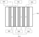
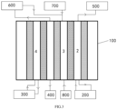
- FIG. 1 is a simple structural schematic diagram of a system for performing urea electrolysis-based hydrogen production and carbon reduction according to an embodiment of the present disclosure.
- the system for alternately performing urea electrolysis-based hydrogen production and carbon reduction includes a housing 1, a first electrode chamber 2, a second electrode chamber 3, and a third electrode chamber 4.
- a first electrode 5, a first separator 6, a second electrode 7, a second separator 8, and a third electrode 9 are successively arranged in the housing 1.
- a space is left between the adjacent two of the first electrode 5, the first separator 6, the second electrode 7, the second separator 8, and the third electrode 9.
- the first electrode chamber 2 is a closed cavity formed by the first electrode 5, the first separator 6, and an inner wall of the housing 1, and is used for producing a hydrogen evolution reaction.
- the first electrode chamber 2 is provided with a first gas outlet, a first inlet, and a first outlet.
- the second electrode chamber 3 is a closed cavity formed by the first separator 6, the second separator 8, and an inner wall of the housing 1.
- the second electrode 7 is provided in the second electrode chamber 3.
- the second electrode chamber 3 is provided with a second gas outlet, a second inlet and a second outlet.
- the third electrode chamber 4 is a closed cavity formed by the second separator 8, the third electrode 9, and the inner wall of the housing 1.
- the second electrode chamber 3 is provided with a third gas outlet, a third inlet, and a third outlet.
- the third electrode chamber 4 and the second electrode chamber 2 can alternately produce the oxidation reaction of urea and the reduction reaction of carbon dioxide.
- a first electrode chamber can produce a hydrogen evolution reaction of water
- a second electrode chamber and a third electrode chamber can alternately produce an oxidation reaction of urea and a reduction reaction of carbon dioxide, so that the carbon dioxide produced from urea electrolysis can be converted in time during the reaction, reducing the mixing pollution of carbon dioxide on the product hydrogen, improving the efficiency of electrolysis-based hydrogen production, and reducing the overall cost of the process.
- carbon dioxide is reduced to form valuable products, avoiding the release of carbon dioxide, achieving the purpose of zero carbon emission.
- the first electrode and the third electrode may be proximate to an inner wall of the housing proximate thereto. In other embodiments of the present disclosure, the first and third electrodes may also be spaced apart from their immediately adjacent housings (as shown in FIG. 1 ).
- the first electrode 5, the first separator 6, the second electrode 7, the second separator 8, and the third electrode 9 can all be welded to the inner wall of the housing 3 or connected to the inner wall of the housing 1 by means of sealing rings, bolts or the like, as long as it is ensured that the first electrode chamber, the second electrode chamber and the third electrode chamber are all closed chambers.
- the shape of the housing 1 is not limited, and the housing 1 may have a cuboid shape, a cube shape, a cylindrical shape, or the like.
- the material of the housing is also not limited and may be a metal material such as stainless steel or a corrosion-resistant plastic material such as PTEF.
- the first electrode 5, the first separator 6, the second electrode 7, the second separator 8, and the third electrode 9 may be arranged parallel to each other, or may be inclined at different angles to each other, so long as the first electrode and the first separator and the housing can constitute the first electrode chamber, the first separator and the second separator and the housing can constitute the second electrode chamber, and the second separator and the third electrode and the housing can constitute the third electrode chamber.
- the housing has a cuboid shape, a cube shape. All the first electrode 5, the first separator 6, the second electrode 7, the second separator 8, and the third electrode 9 are arranged in parallel and perpendicular to the top and bottom of the housing.
- the first electrode chamber 2 is provided with an aqueous alkaline solution, preferably a 20-30 wt% potassium hydroxide solution.
- an alkaline urea solution is provided in the electrode chamber that produces the oxidation reaction of urea
- a CO 2 -saturated bicarbonate solution is provided in the electrode chamber that produces the reduction reaction of carbon dioxide.
- the alkaline urea solution is a mixed solution of potassium hydroxide, urea, and water, and the contents of potassium hydroxide and urea in the mixed solution are 20-30 wt% and 1-10 wt%, respectively.
- the pH of the CO 2 -saturated bicarbonate solution is 7-11, preferably 9-10, in order to increase the selectivity of carbon dioxide reduction over HER.
- the concentration of bicarbonate in the CO 2 -saturated bicarbonate solution is 0.1-1 M, and the bicarbonate is sodium bicarbonate or potassium bicarbonate.
- a second gas inlet is further provided in the second electrode chamber 3 and a third gas inlet is further provided in the third electrode chamber 4 in order to allow the introduction of exogenous carbon dioxide or/and the generated carbon dioxide in the mixed gas after the reduction reaction of carbon dioxide.
- the alkaline aqueous solution, alkaline urea solution and CO 2 -saturated bicarbonate solution all circulate, which can promote gas-liquid mixing and mass transfer within each electrode chamber, and improve the reaction kinetic rate.
- the first inlet is in communication with the outlet of the alkaline aqueous solution reservoir 200 via a first line; the first outlet is in communication with the inlet of the alkaline aqueous solution reservoir 200 via a second line; the second inlet is in communication with the outlet of the alkaline urea solution reservoir 300 and the outlet of the alkaline aqueous solution reservoir 200 or the outlet of the lye reservoir 800 via a third line and a fourth line, respectively; the second outlet is in communication with the inlet of the alkaline urea solution reservoir 300 and the inlet of the product reservoir 400 via a fifth line and a sixth line, respectively; the third inlet is communicated with the outlet of the alkaline urea solution reservoir 300 and the outlet of the alkaline aqueous solution reservoir 200 or the outlet of the
- a circulation pump and a valve are installed on each line (as shown in FIGs. 2 and 3 , in which the circulation pump and the valve are not shown).
- the circulation of the alkaline aqueous solution in the first electrode chamber, the circulation of the alkaline urea solution in the second electrode chamber or the third electrode chamber that produces the oxidation reaction of urea, and the circulation of CO 2 -saturated bicarbonate solution in the third chamber or second electrode chamber that produces the reduction reaction of carbon dioxide can be controlled by controlling the on/off of valves on different communication lines.
- the alkaline aqueous solution reservoir may be shared with the alkaline aqueous solution reservoir in communication with the first inlet of the first electrode chamber that produces the hydrogen evolution reaction.
- the lye reservoir may be another separately provided potassium hydroxide solution reservoir.
- the alkaline aqueous solution reservoir shall be regularly supplied with water to maintain a certain alkaline concentration.
- the carbon dioxide generated at the third electrode or the second electrode (or the carbon dioxide generated at the third electrode or the second electrode and the carbon dioxide inputted from an external source) is allowed to react with the circulating alkaline solution entering the third electrode chamber or the second electrode chamber that produces the reduction reaction of carbon dioxide to reach saturation, and then the electrification reaction is started.
- the preparation of the alkaline urea solution in the alkaline urea solution reservoir can include introducing the potassium hydroxide solution in the potassium hydroxide solution reservoir and the urea solution in the urea solution reservoir respectively into the alkaline urea solution reservoir in a proportion and mixing uniformly.
- the potassium hydroxide solution reservoir can be shared with the alkaline aqueous solution reservoir of the first electrode chamber that produces the hydrogen evolution reaction.
- the first gas outlet, the first inlet and the first outlet are provided on the housing 1 corresponding to the first electrode chamber 2, for example, the first gas outlet and the first inlet are provided on the top of the housing 1 and the first outlet is provided on the bottom of the housing 1.
- the second gas inlet, the second gas outlet, the second inlet, and the second outlet are all provided on the housing 1 corresponding to the second electrode chamber 3.
- the third gas inlet, the third gas outlet, the third inlet, and the third outlet are all provided on the housing 1 corresponding to the third electrode chamber 4.
- the second gas inlet, the second gas outlet, the second inlet, the third gas inlet, the third gas outlet, and the third inlet are all provided at the top of the housing 1, and the second outlet and the third outlet are provided at the bottom of the housing 1.
- the first electrode 5 is a conductive substrate having a surface provided with a loading layer.
- the conductive substrate may be a metal plate, such as a copper plate, a stainless-steel plate, etc.
- the conductive substrate may be a porous plate, such as a metal foam or a carbon material, wherein the metal foam may be nickel foam, copper foam, iron-nickel foam, nickel-molybdenum foam, etc. and the carbon material may be graphite, activated carbon, etc.
- the material of the loading layer is one or an alloy of two or more of P, Ru, Rh, Ir, Ni, Co, Fe, Zn, and Ti.
- the conductive substrate has a thickness of 100-500 micrometers, and the loading layer has a thickness of 5-100 nanometers.
- the method for preparing a conductive substrate having a surface provided with a loading layer includes: providing the material of the loading layer on the conductive substrate by means of electrodeposition, impregnation, etc. and the specific forming method, process conditions, etc. are conventional techniques in the art and are not the focus of the embodiments of the present disclosure.
- the electrochemical reaction of the first electrode surface is as follows: 6H 2 O+6e - ⁇ 3H 2 +6OH - .
- the first electrode is connected to an external power supply.
- both the first separator 6 and the second separator 8 may be selected to be a porous separator, such as a commercial Zirfon membrane (polysulfone loaded with 85 wt% ZrO 2 nanoparticles) or the like. In other embodiments of the present disclosure, both the first separator 6 and the second separator 8 may be selected as anion exchange membranes having OH - conductivity.
- the anion exchange membrane may be selected from a polyarylether membrane, a polyethylene membrane, a polystyrene membrane, a polytetrafluoroethylene membrane, or a polyphenyl membrane modified with a cationic group, wherein the cationic group may be selected from a polyalkyl ammonium salt, an imidazolium salt, a pyridinium salt, or a piperidinium salt, for example, the polyalkyl ammonium salt may be selected from a trialkyl quaternary ammonium salt, a trimethyl quaternary ammonium salt, etc.
- the method of preparing an anion exchange membrane having OH - conductivity includes: monomer polymerization (a monomer modified with a cationic group is directly polymerized with a structural group.
- monomer polymerization a monomer modified with a cationic group is directly polymerized with a structural group.
- QAPPT quaternary ammonium poly(N-methyl-piperidine-co-p-terphenyl)
- the second electrode 7 and the third electrode 9 are both reticulated conductive substrates loaded with an active catalytic layer on the surface.
- the reticulated conductive substrate can be selected from metal materials such as stainless steel and copper, and can also be selected from carbon materials such as graphite and activated carbon; the surface mesh diameter of the reticulated conductive substrate is 0.5-1 mm, and the surface porosity is more than 80%, which facilitates the passage of gas.
- the material of the active catalytic layer includes a first active component and a second active component.
- the first active component is a component having electrocatalytic activity for the reduction of carbon dioxide, such as one or an alloy of two or more of Cu, Pb, Hg, Tl, In, Sn, Cd, and Bi.
- the second active component is a component having electrocatalytic activity for the oxidation of urea, such as one or an alloy of two or more of Pt, Ru, Rh, Ir, Ni, Co, Fe, Zn, and Ti.
- the second electrode and the third electrode have the activity of catalyzing the oxidation of urea and catalyzing the reduction of carbon dioxide simultaneously by using the active catalytic layer of multiple active components.
- the reticulated conductive substrate has a thickness of 100-500 microns; and the thickness of the active catalytic layer is 5-100 nm.
- the method of preparing a reticulated conductive substrate loaded with an active catalytic layer on the surface includes: providing the material of the catalytically active layer on the reticulated conductive substrate by means of electrodeposition, impregnation, etc. and the specific forming method, process conditions, etc. are conventional techniques in the art and are not the focus of the embodiments of the present disclosure.
- the second/third electrode is connected to the positive electrode of the external power supply.
- the electrochemical reaction at the second/third electrode surface is as follows: CO(NH 2 ) 2 +6OH - ⁇ N 2 +5H 2 O+CO 2 +6e - .
- the second electrode/third electrode is connected to the negative electrode of the external power supply, and the electrochemical reactions at the surface are as follows: CO 2 +H 2 O+2e - ⁇ HCOOH+OH - ; CO 2 +3H 2 O+4e - ⁇ HCHO+4OH - ; and CO 2 +3H 2 O+6e - ⁇ CH 3 OH+2OH - .
- valves may be installed at each of the gas outlet, the gas inlet, the liquid inlet, and the liquid outlet as needed.
- the working principle of the system for alternately performing urea electrolysis-based hydrogen production and carbon reduction according to the embodiments of the present disclosure is as follows:
- the first gas outlet is in communication with the hydrogen storage tank 500 or the hydrogen line;
- the first inlet is in communication with the outlet of the alkaline aqueous solution reservoir 200;
- the first outlet is in communication with the inlet of the alkaline aqueous solution reservoir 200;
- a circulation pump is further installed on each communication line between the first inlet, the first outlet, and the alkaline aqueous solution reservoir 200.
- the alkaline aqueous solution enters the first electrode chamber 2 and circulates in the first electrode chamber 2.
- the first electrode 5 and the third electrode 9 are both connected to the negative electrode of the external power supply.
- the second electrode 7 is connected to the positive electrode of the external power supply.
- the second gas inlet and the second gas outlet are closed.
- the second inlet is in communication with the outlet of the alkaline urea solution reservoir 300 and the second outlet is in communication with the inlet of the alkaline urea solution 300.
- the third gas outlet is in communication with a nitrogen/carbon dioxide gas separator 600, and the third gas inlet may be closed without ventilation or is connected to an exogenous carbon dioxide line 700 from thermal power plants, chemical plants, steelmaking, and other waste gas capture systems, or/and is in communication with a carbon dioxide outlet connected to the nitrogen/carbon dioxide gas separator 600.
- the third inlet is in communication with the outlet of the alkaline aqueous solution reservoir 200, and the third outlet is in communication with the inlet of the product reservoir 400.
- a circulation pump is mounted on each communication line between the second inlet, the second outlet, and the alkaline aqueous solution reservoir 200.
- Circulation pumps are mounted on the communication line between the third inlet and the alkaline urea solution reservoir 300, and the communication line between the third outlet and the inlet of the product reservoir 400.
- the alkaline urea aqueous solution enters the second electrode chamber and circulates in the second electrode chamber 3.
- the alkaline aqueous solution enters the third electrode chamber 4, and circulates in the third electrode chamber 4.
- the electrolytic alkaline aqueous solution in the first electrode chamber 2 is electrolyzed to produce a hydrogen evolution reaction.
- the generated hydrogen is collected via a hydrogen storage tank 500 or is used via a hydrogen line.
- OH - enters the second electrode chamber 3 via the first separator 6.
- the second electrode chamber 3 produces the oxidation reaction of urea.
- the generated carbon dioxide enters the third electrode chamber 4 via the second separator 8.
- the third electrode 9 is initially unpowered, so that the carbon dioxide generated in the oxidation reaction of urea in the second electrode chamber (or the carbon dioxide generated by the carbon dioxide generated in the oxidation reaction of urea in the second electrode chamber and the carbon dioxide imported from an external source; or carbon dioxide produced by the carbon dioxide produced in the oxidation reaction of urea in the second electrode chamber and carbon dioxide obtained after separation and purification of the gases after the reduction reaction of carbon dioxide in the third electrode chamber; or carbon dioxide produced by the carbon dioxide produced in the oxidation reaction of urea in the second electrode chamber, carbon dioxide obtained after separation and purification of the gas after the reduction reaction of carbon dioxide in the third electrode chamber, and carbon dioxide imported from an external source) reacts with the circulating alkaline liquid entering the third electrode chamber 4 to reach saturation, so as to ensure that there is a CO 2 -saturated bicarbonate solution available for the reduction reaction of carbon dioxide in the third electrode chamber 4.
- the third electrode 9 is powered for the reaction, and the third electrode chamber 4 produces the reduction reaction of carbon dioxide.
- the carbon dioxide from the second electrode chamber 3 or the carbon dioxide from the second electrode chamber 3 and the exogenous carbon dioxide entering from the third gas inlet reacts with the CO 2 -saturated bicarbonate solution in the third electrode chamber 4 to convert the carbon dioxide into formic acid, methanol and formaldehyde, which are flow out of the third electrode chamber 4 via the third outlet and are collected via the product reservoir 400.
- a small amount of carbon dioxide which has not reacted completely and the nitrogen generated from the oxidation of urea in the second electrode chamber 3 enter the nitrogen/carbon dioxide gas separator 600 via the third gas outlet for separation.
- the separated carbon dioxide can be recycled back to the third electrode chamber 4 for reuse.
- the nitrogen is transported as a product.
- the nitrogen/carbon dioxide gas separator employs a membrane separator.
- the first electrode chamber produces a reaction at the first electrode surface: 2H 2 O+2e - ⁇ H 2 +2OH - ;
- the second electrode chamber produces a reaction at the second electrode surface: CO(NH 2 ) 2 +6OH - ⁇ N 2 +5H 2 O+CO 2 +6e - ;
- the third electrode chamber produces reactions at the third electrode surface: CO 2 +H 2 O+2e - ⁇ HCOOH+OH - ; CO 2 +3H 2 O+4e - ⁇ HCHO+4OH - ; and CO 2 +3H 2 O+6e - ⁇ CH 3 OH+2OH - .
- the first electrode 5 and the second electrode 7 are both connected to the negative electrode of the external power supply, and the third electrode 9 is connected to the positive electrode of the external power supply.
- the first electrode chamber 2 produces a hydrogen evolution reaction
- the second electrode chamber 3 produces a reduction reaction of carbon dioxide
- the third electrode chamber 4 produces an oxidation reaction of urea.
- the first electrode chamber produces a reaction at the first electrode surface: 2H 2 O+2e - ⁇ H 2 +2OH - ;
- the second electrode chamber produces reactions at the second electrode surface: CO 2 +H 2 O+2e - ⁇ HCOOH+OH - ; CO 2 +3H 2 O+4e - ⁇ HCHO+4OH - ; and CO 2 +3H 2 O+6e - ⁇ CH 3 OH+2OH;
- the third electrode chamber produces a reaction at the third electrode surface: CO(NH 2 ) 2 +6OH - ⁇ N 2 +5H 2 O+CO 2 +6e - .
- the first duty cycle and the second duty cycle alternate throughout the operation.
- the criteria for the end of the first duty cycle are: the carbon dioxide generated in the second electrode chamber 3 is absorbed by the lye in the third electrode chamber 4, while the concentration of carbon dioxide in the second electrode chamber 3 is controlled to prevent the first separator 6 and the second separator 8 from being blocked by carbonate.
- the criteria for determining that the first duty cycle needs to be switched to the second duty cycle is the pressure in the second electrode chamber 3 is increased by 5-10% (monitored by connecting a pressure gauge).
- the criteria for the end of the second duty cycle are: the carbon dioxide generated in the third electrode chamber 4 is absorbed by the lye in the second electrode chamber 3, while the carbon dioxide concentration in the third electrode chamber 4 is controlled to prevent the second separator 8 from being blocked by carbonate.
- the criteria for determining that the second duty cycle needs to be switched to the first duty cycle is the pressure in the third electrode chamber 4 is increased by 5-10% (monitored by connecting a pressure gauge).
- continuous urea consumption and timely conversion consumption of carbon dioxide in the electrolysis system are realized in time through the switching between the conversion reaction of carbon dioxide and the oxidation reaction of urea, so as to avoid the consumption of carbon dioxide to hydroxyl ions in the alkaline system of the first electrode chamber, reduce the fouling of the electrolysis separator (the first separator), and improve the efficiency of the electrolysis-based hydrogen production reaction.
- Carbon dioxide is reduced to form a valuable liquid product, which is beneficial for the next cycle to promote the equilibrium of the electrolysis reaction to move forward, reduce the mixing pollution of carbon dioxide to the product hydrogen while improving the overall reaction efficiency, and avoiding the release of carbon dioxide to achieve the goal of zero carbon emission.
- the system for urea electrolysis-based hydrogen production and carbon reduction according to the embodiment of the present disclosure includes a system 100 for alternately performing urea electrolysis-based hydrogen production and carbon reduction according to the embodiment of the present disclosure, an external power supply (not shown), an alkaline aqueous solution reservoir 200, an alkaline urea solution reservoir 300, and a product reservoir 400.
- the first gas outlet is in communication with a hydrogen storage tank 500 or a hydrogen line.
- the first inlet is in communication with an outlet of the alkaline aqueous solution reservoir 200.
- the first outlet is in communication with an inlet of the alkaline aqueous solution reservoir 200.
- the external power supply includes at least one positive electrode and at least two negative electrodes.
- the first electrode 5 and the third electrode 9 are respectively connected to one negative electrode, and the second electrode 7 is connected to the positive electrode;
- the second inlet is in communication with an outlet of the alkaline urea solution reservoir 300, and the second outlet is in communication with an inlet of the alkaline urea solution reservoir 300;
- the third inlet is in communication with the outlet of the alkaline aqueous solution reservoir 200 or the outlet of the lye reservoir 800, and the third outlet is in communication with an inlet of the product reservoir 400;
- the third gas outlet is in communication with a nitrogen/carbon dioxide gas separator 600, and a carbon dioxide outlet of the nitrogen/carbon dioxide gas separator 600 is in communication with the third gas inlet;
- the third gas inlet is in communication with an exogenous carbon dioxide line 700.
- the first electrode 5 and second electrode 7 are respectively connected to one negative electrode, and the third electrode 9 is connected to the positive electrode;
- the third inlet is in communication with the outlet of the alkaline urea solution reservoir 300, and the third outlet is in communication with the inlet of the alkaline urea solution reservoir 300;
- the second inlet is in communication with the outlet of the alkaline aqueous solution reservoir 200 or the outlet of the lye reservoir 800, and the second outlet is in communication with the inlet of the product reservoir 400;
- the second gas outlet is in communication with the nitrogen/carbon dioxide gas separator 600, and the carbon dioxide outlet of the nitrogen/carbon dioxide gas separator 600 is in communication with the second gas inlet; and the second gas inlet is in communication with the exogenous carbon dioxide line 700.
- the nitrogen/carbon dioxide gas separator employs a membrane separator.
- circulation pumps are installed on the communication line between the first inlet and the outlet of the alkaline aqueous solution reservoir 200, the communication line between the first outlet and the outlet of the alkaline aqueous solution reservoir 200, the communication line between the second inlet and the outlet of the alkaline urea solution reservoir 300, the communication line between the second outlet and the inlet of the alkaline urea solution reservoir 300, the communication line between the third inlet and the outlet of the alkaline aqueous solution reservoir 200 or the outlet of the lye reservoir 800, and the communication line between the third outlet and the inlet of the product reservoir 400.
- circulation pumps are installed on the communication line between the first inlet and the outlet of the alkaline aqueous solution reservoir 200, the communication line between the first outlet and the outlet of the alkaline aqueous solution reservoir 200, the communication line between the third inlet and the outlet of the alkaline urea solution reservoir 300, the communication line between the third outlet and the inlet of the alkaline urea solution reservoir 300, the communication line between the second inlet and the outlet of the alkaline aqueous solution reservoir 200 or the outlet of the lye reservoir 800, and the communication line between the second outlet and the inlet of the product reservoir 400.
- valves can be installed on each line according to needs, which is a conventional technique in the art and does not fall within the protection focus of the present disclosure.
- the operating principle of the system for urea electrolysis-based hydrogen production and carbon reduction according to the embodiments of the present disclosure is substantially the same as the operating principle of the system for alternately performing urea electrolysis-based hydrogen production and carbon reduction according to the embodiments of the present disclosure, and will not be described in detail herein.
- references to descriptions of the terms “one embodiment”, “some embodiments”, “example”, “specific examples”, or “some examples”, etc. mean that a particular feature, structure, material, or characteristic described in connection with the embodiment or example is included in at least one embodiment or example of the present disclosure.
- schematic representations of the terms above do not necessarily refer to the same embodiment or example.
- the particular features, structures, materials, or characteristics described may be combined in any suitable manner in any one or more embodiments or examples.
- the different embodiments or examples and the features of the different embodiments or examples described in this description can be integrated and combined by a person skilled in the art without contradicting each other.
Landscapes
- Chemical & Material Sciences (AREA)
- Organic Chemistry (AREA)
- Engineering & Computer Science (AREA)
- Chemical Kinetics & Catalysis (AREA)
- Electrochemistry (AREA)
- Materials Engineering (AREA)
- Metallurgy (AREA)
- Inorganic Chemistry (AREA)
- Electrolytic Production Of Non-Metals, Compounds, Apparatuses Therefor (AREA)
Abstract
Description
- This disclosure relates to the technical field of hydrogen production and carbon dioxide utilization, specifically to a system and method for alternately performing urea electrolysis-based hydrogen production and carbon reduction, and an application system.
- At present, water electrolysis-based hydrogen production is the only technological approach that can achieve industrial green hydrogen production, which is of great significance for achieving the dual carbon goal. In order to improve the cost competitiveness of green hydrogen produced by water electrolysis-based hydrogen production, it is necessary to further reduce the electricity consumption of water electrolysis-based hydrogen production. Urea, as an electrolyte additive, can theoretically reduce the theoretical energy consumption of electrolysis-based hydrogen production (only 1/5 of direct electrolysis of water). In addition, urea can be obtained from industrial waste or human and animal urine, with the additional effect of purifying wastewater while obtaining hydrogen, making it a good way to reduce hydrogen production costs.
- However, an electrolysis-based hydrogen system adding urea as an electrolyte has the following problems: carbon dioxide generated at the anode is easily converted to carbonate in an alkaline environment, which tends to form carbonate crystals and cause separator clogging, which affects the performance of the electrolysis-based hydrogen production, resulting in higher voltages, lower lifetimes, and so on; and carbon dioxide depletion of alkaline ions results in additional costs. In addition, even if carbon dioxide is not converted into carbonate, its emission may cause pollution; cross-separator mixing of carbon dioxide with hydrogen can result in reduced hydrogen quality, leading to increased subsequent purification costs. Therefore, there is a need to solve the problem of carbon dioxide generated in the process of urea electrolysis-based hydrogen production, avoiding the direct emission of carbon dioxide and pollution of hydrogen, as well as the consumption of alkaline ions and carbonate fouling caused by carbon dioxide.
- It is a good way to convert carbon dioxide into formic acid, methanol, and other liquid organic compounds through reduction reactions, which are further used as industrial raw materials or fuels in chemical production, fuel cell power generation, and other fields. However, the carbon dioxide conversion reaction will cause additional costs. Electrochemical reduction is a mild and efficient production method, but a suitable system needs to be designed to realize the coupling of urea electrolysis and carbon dioxide reduction.
- Thus, it is an objective of the present disclosure to provide a system for alternately performing urea electrolysis-based hydrogen production and carbon reduction, wherein a first electrode chamber can produce a hydrogen evolution reaction of water, and a second electrode chamber and a third electrode chamber can alternately produce the oxidation reaction of urea and reduction reaction of carbon dioxide, so that the carbon dioxide produced from urea electrolysis can be converted in time during the reaction, reducing the mixing pollution of carbon dioxide on the product hydrogen, improving the efficiency of electrolysis-based hydrogen production, and reducing the overall cost of the process. At the same time, through electrochemical reaction, carbon dioxide is reduced to form valuable products, avoiding the release of carbon dioxide, and achieving the purpose of zero carbon emission.
- It is another objective of the present disclosure to provide a method for alternately performing urea electrolysis-based hydrogen production and carbon reduction.
- It is yet another objective of the present disclosure to provide a system for alternately performing urea electrolysis-based hydrogen production and carbon reduction.
- In order to achieve the above objectives, proposed in an embodiment of a first aspect of the present disclosure is a system for alternately performing urea electrolysis-based hydrogen production and carbon reduction, including a housing, a first electrode chamber, a second electrode chamber and a third electrode chamber;
- a first electrode, a first separator, a second electrode, a second separator, and a third electrode are successively arranged in the housing, and a space is left between the adjacent two of the first electrode, the first separator, the second electrode, the second separator, and the third electrode;
- the first electrode chamber is a closed cavity formed by the first electrode, the first separator, and an inner wall of the housing, and is used for producing a hydrogen evolution reaction; the first electrode chamber is provided with a first gas outlet, a first inlet, and a first outlet;
- the second electrode chamber is a closed cavity formed by the first separator, the second separator, and an inner wall of the housing; the second electrode is provided in the second electrode chamber; the second electrode chamber is provided with a second gas outlet, a second inlet and a second outlet; and
- the third electrode chamber is a closed cavity formed by the second separator, the third electrode and the inner wall of the housing; the second electrode chamber is provided with a third gas outlet, a third inlet, and a third outlet; the third electrode chamber and the second electrode chamber can alternately produce the oxidation reaction of urea and the reduction reaction of carbon dioxide.
- In the system for alternately performing urea electrolysis-based hydrogen production and carbon reduction, a first electrode chamber can produce the hydrogen evolution reaction of water, and a second electrode chamber and a third electrode chamber can alternately produce the urea oxidation reaction and reduction reaction of carbon dioxide, so that the carbon dioxide produced from urea electrolysis can be converted in time during the reaction, reducing the mixing pollution of carbon dioxide on the product hydrogen, improving the efficiency of electrolysis-based hydrogen production, and reducing the overall cost of the process. At the same time, through electrochemical reaction, carbon dioxide is reduced to form valuable products, avoiding the release of carbon dioxide, and achieving the purpose of zero carbon emission.
- In some embodiments of the present disclosure, an alkaline aqueous solution is provided in the first electrode chamber; in the second electrode chamber and the third electrode chamber, an alkaline urea solution is provided in the electrode chamber that produces the oxidation reaction of urea, and a CO2-saturated bicarbonate solution is provided in the electrode chamber that produces the reduction reaction of carbon dioxide.
- In some embodiments of the present disclosure, the second electrode chamber is further provided with a second gas inlet, and the third electrode chamber is further provided with a third gas inlet; and all of the alkaline aqueous solution, the alkaline urea solution and the CO2-saturated bicarbonate solution are circulated.
- In some embodiments of the present disclosure, the alkaline aqueous solution is a 20-30 wt% potassium hydroxide solution; the alkaline urea solution is a mixed solution of potassium hydroxide, urea, and water, and the contents of potassium hydroxide and urea in the mixed solution are 20-30 wt% and 1-10 wt%, respectively; the pH of the CO2-saturated bicarbonate solution is 7-11; the concentration of bicarbonate in the CO2-saturated bicarbonate solution is 0.1-1 M, and the bicarbonate is sodium bicarbonate or potassium bicarbonate.
- In some embodiments of the present disclosure, the first electrode is a conductive substrate having a surface provided with a loading layer; the conductive substrate is a metal plate or a porous plate; the material of the loading layer is one or an alloy of two or more of Pt, Ru, Rh, Ir, Ni, Co, Fe, Zn, and Ti.
- In some embodiments of the present disclosure, the first separator and the second separator are both porous separators or anion exchange membranes with OH- conductivity; the porous separator is a Zirfon membrane; the anion exchange membrane is a polyarylether membrane, a polyethylene membrane, a polystyrene membrane, a polytetrafluoroethylene membrane, or a polyphenyl membrane modified with a cationic group; the cationic group is a polyalkylammonium, imidazolium, pyridinium, or piperidinium salt.
- In some embodiments of the present disclosure, the second electrode and the third electrode are both reticulated conductive substrates loaded with an active catalytic layer on the surface; the reticulated conductive substrate is a metal material or a carbon material; the material of the active catalytic layer includes a first active component and a second active component; the first active component is a component having electrocatalytic activity for the reduction of carbon dioxide and the second active component is a component having electrocatalytic activity for the oxidation of urea.
- In some embodiments of the present disclosure, the first active component is one or an alloy of two or more of Cu, Pb, Hg, Tl, In, Sn, Cd, and Bi; and the second active component is one or an alloy of two or more of Pt, Ru, Rh, Ir, Ni, Co, Fe, Zn, and Ti. In order to achieve the above objective, an embodiment of a second aspect of the present disclosure proposes a method for alternately performing urea electrolysis-based hydrogen production and carbon reduction, including:
- in a first duty cycle, connecting both the first electrode and the third electrode to the negative electrode of the external power supply, and connecting the second electrode to the positive electrode of the external power supply, wherein the first electrode chamber produces a hydrogen evolution reaction, the second electrode chamber produces an oxidation reaction of urea, and the third electrode chamber produces a reduction reaction of carbon dioxide;
- in a second duty cycle, connecting both the first electrode and the second electrode to the negative electrode of the external power supply, and connecting the third electrode to the positive electrode of the external power supply, wherein the first electrode chamber produces the hydrogen evolution reaction, the second electrode chamber produces the reduction reaction of carbon dioxide, and the third electrode chamber produces the oxidation reaction of urea;
- the first duty cycle and the second duty cycle are performed alternately; there are four sources of carbon dioxide that produces the reduction reaction of carbon dioxide during the first and second duty cycles:
- the first type, the carbon dioxide that produces the reduction reaction of carbon dioxide during the first and second duty cycles is the carbon dioxide produced by urea oxidation;
- the second type, the carbon dioxide that produces the reduction reaction of carbon dioxide during the first and second duty cycles is carbon dioxide produced by urea oxidation and carbon dioxide obtained after the separation and purification of the gases after the reduction reaction of carbon dioxide;
- the third type, the carbon dioxide that produces the reduction reaction of carbon dioxide during the first and second duty cycles is carbon dioxide produced by urea oxidation and exogenous carbon dioxide; and
- the fourth type, the carbon dioxide that produces the reduction reaction of carbon dioxide during the first and second duty cycles is carbon dioxide produced by urea oxidation, obtained after the separation and purification of the gases after the reduction reaction of carbon dioxide, and exogenous carbon dioxide.
- Advantageous effects of the method for alternately performing urea electrolysis-based hydrogen production and carbon reduction according to the embodiments of the present disclosure are substantially the same as those of the system for alternately performing urea electrolysis-based hydrogen production and carbon reduction according to the embodiments of the present disclosure, and will not be described in detail herein.
- In some embodiments of the present disclosure, switching to the second duty cycle is performed when the pressure in the second electrode chamber is increased by 5-10% during the first duty cycle; and switching to the first duty cycle is performed when the pressure in the third electrode chamber is increased by 5-10% in the second duty cycle.
- In order to achieve the above objective, proposed in an embodiment of a third aspect of the present disclosure is a system for urea electrolysis-based hydrogen production and carbon reduction including the system for alternately performing urea electrolysis-based hydrogen production and carbon reduction as described above, an external power supply, an alkaline aqueous solution reservoir, an alkaline urea solution reservoir, and a product reservoir; wherein the first gas outlet is in communication with a hydrogen storage tank or a hydrogen line; the first inlet is in communication with an outlet of the alkaline aqueous solution reservoir; the first outlet is in communication with an inlet of the alkaline aqueous solution reservoir; the external power supply includes at least one positive electrode and at least two negative electrodes.
- In some embodiments of the present disclosure, based on the oxidation reaction of urea producing in the second electrode chamber, and the reduction reaction of carbon dioxide producing in the third electrode chamber, the first electrode and the third electrode are respectively connected to one negative electrode, and the second electrode is connected to the positive electrode; the second inlet is in communication with an outlet of the alkaline urea solution reservoir, and the second outlet is in communication with an inlet of the alkaline urea solution reservoir; the third inlet is in communication with the outlet of the alkaline aqueous solution reservoir or the outlet of the lye reservoir, and the third outlet is in communication with an inlet of the product reservoir; the third gas outlet is in communication with a nitrogen/carbon dioxide gas separator, and a carbon dioxide outlet of the nitrogen/carbon dioxide gas separator is in communication with the third gas inlet; the third gas inlet is in communication with an exogenous carbon dioxide line.
- In some embodiments of the present disclosure, based on the reduction reaction of carbon dioxide producing in the second electrode chamber, and the oxidation reaction of urea producing in the third electrode chamber, the first electrode and second electrode are respectively connected to one negative electrode, and the third electrode is connected to the positive electrode; the third inlet is in communication with the outlet of the alkaline urea solution reservoir, and the third outlet is in communication with the inlet of the alkaline urea solution reservoir; the second inlet is in communication with the outlet of the alkaline aqueous solution reservoir or the outlet of the lye reservoir, and the second outlet is in communication with the inlet of the product reservoir; the second gas outlet is in communication with the nitrogen/carbon dioxide gas separator, and the carbon dioxide outlet of the nitrogen/carbon dioxide gas separator is in communication with the second gas inlet; and the second gas inlet is in communication with the exogenous carbon dioxide line.
- Advantageous effects of the system for performing urea electrolysis-based hydrogen production and carbon reduction according to the embodiments of the present disclosure are substantially the same as those of the system for alternately performing urea electrolysis-based hydrogen production and carbon reduction according to the embodiments of the present disclosure, and will not be described in detail herein.
- In some embodiments of the present disclosure, based on the oxidation reaction of urea producing in the second electrode chamber and the reduction reaction of carbon dioxide producing in the third electrode chamber, circulation pumps are installed on the communication line between the first inlet and the outlet of the alkaline aqueous solution reservoir, the communication line between the first outlet and the outlet of the alkaline aqueous solution reservoir, the communication line between the second inlet and the outlet of the alkaline urea solution reservoir, the communication line between the second outlet and the inlet of the alkaline urea solution reservoir, the communication line between the third inlet and the outlet of the alkaline aqueous solution reservoir or the outlet of the lye reservoir, and the communication line between the third outlet and the inlet of the product reservoir.
- In some embodiments of the present disclosure, based on the reduction reaction of carbon dioxide producing in the second electrode chamber and the oxidation reaction of urea producing in the third electrode chamber, circulation pumps are installed on the communication line between the first inlet and the outlet of the alkaline aqueous solution reservoir, the communication line between the first outlet and the outlet of the alkaline aqueous solution reservoir, the communication line between the third inlet and the outlet of the alkaline urea solution reservoir, the communication line between the third outlet and the inlet of the alkaline urea solution reservoir, the communication line between the second inlet and the outlet of the alkaline aqueous solution reservoir or the outlet of the lye reservoir, and the communication line between the second outlet and the inlet of the product reservoir.
- Additional aspects and advantages of the present disclosure will be set forth in part in the description which follows and, in part, will be obvious from the description, or may be learned by practice of the present disclosure.
- The foregoing and/or additional aspects and advantages of the present disclosure will become apparent and readily appreciated from the following description of the embodiments, taken in conjunction with the accompanying drawings of which:
-
FIG. 1 is a simple structural schematic diagram of a system for performing urea electrolysis-based hydrogen production and carbon reduction according to an embodiment of the present disclosure. -
FIG. 2 is a simple structural schematic diagram of a system for performing urea electrolysis-based hydrogen production and carbon reduction in a duty state (a second electrode chamber produces an oxidation reaction of urea and a third electrode chamber produces a reduction reaction of carbon dioxide) according to an embodiment of the present disclosure. -
FIG. 3 is a simple structural schematic diagram of a system for performing urea electrolysis-based hydrogen production and carbon reduction in a duty state (a second electrode chamber produces a reduction reaction of carbon dioxide and a third electrode chamber produces an oxidation reaction of urea) according to an embodiment of the present disclosure. - 1-housing; 2-first electrode chamber; 3-second electrode chamber; 4-third electrode chamber; 5-first electrode; 6-first separator; 7-second electrode; 8-second separator; 9-third electrode; 100-system for alternating urea electrolysis-based hydrogen production and carbon reduction; 200-alkaline aqueous solution reservoir; 300-alkaline urea solution reservoir; 400-product reservoir; 500-hydrogen storage tank; 600-nitrogen/carbon dioxide gas separator; 700-exogenous carbon dioxide line; 800-lye reservoir.
- Reference will now be made in detail to the embodiments of the present disclosure, examples of which are illustrated in the accompanying drawings. The embodiments described below with reference to the figures are exemplary and are intended to be illustrative of the present disclosure and are not to be construed as limiting the present disclosure.
- The materials and equipment referred to in the examples of this disclosure, unless otherwise specified, are commercially available materials and equipment; the methods referred to in the examples of the present disclosure, unless otherwise specified, are conventional experimental methods.
- A system for alternately performing urea electrolysis-based hydrogen production and carbon reduction, a method for alternately performing urea electrolysis-based hydrogen production and carbon reduction, and a system for urea electrolysis-based hydrogen production and carbon reduction according to embodiments of the present disclosure will be described below with reference to the accompanying drawings.
FIG. 1 is a simple structural schematic diagram of a system for performing urea electrolysis-based hydrogen production and carbon reduction according to an embodiment of the present disclosure. - As shown in
FIG. 1 , the system for alternately performing urea electrolysis-based hydrogen production and carbon reduction according to an embodiment of the present disclosure includes a housing 1, afirst electrode chamber 2, asecond electrode chamber 3, and athird electrode chamber 4. Afirst electrode 5, afirst separator 6, asecond electrode 7, asecond separator 8, and athird electrode 9 are successively arranged in the housing 1. A space is left between the adjacent two of thefirst electrode 5, thefirst separator 6, thesecond electrode 7, thesecond separator 8, and thethird electrode 9. Thefirst electrode chamber 2 is a closed cavity formed by thefirst electrode 5, thefirst separator 6, and an inner wall of the housing 1, and is used for producing a hydrogen evolution reaction. Thefirst electrode chamber 2 is provided with a first gas outlet, a first inlet, and a first outlet. Thesecond electrode chamber 3 is a closed cavity formed by thefirst separator 6, thesecond separator 8, and an inner wall of the housing 1. Thesecond electrode 7 is provided in thesecond electrode chamber 3. Thesecond electrode chamber 3 is provided with a second gas outlet, a second inlet and a second outlet. Thethird electrode chamber 4 is a closed cavity formed by thesecond separator 8, thethird electrode 9, and the inner wall of the housing 1. Thesecond electrode chamber 3 is provided with a third gas outlet, a third inlet, and a third outlet. Thethird electrode chamber 4 and thesecond electrode chamber 2 can alternately produce the oxidation reaction of urea and the reduction reaction of carbon dioxide. - In the system for alternately performing urea electrolysis-based hydrogen production and carbon reduction, a first electrode chamber can produce a hydrogen evolution reaction of water, and a second electrode chamber and a third electrode chamber can alternately produce an oxidation reaction of urea and a reduction reaction of carbon dioxide, so that the carbon dioxide produced from urea electrolysis can be converted in time during the reaction, reducing the mixing pollution of carbon dioxide on the product hydrogen, improving the efficiency of electrolysis-based hydrogen production, and reducing the overall cost of the process. At the same time, through electrochemical reaction, carbon dioxide is reduced to form valuable products, avoiding the release of carbon dioxide, achieving the purpose of zero carbon emission.
- In some embodiments of the present disclosure, the first electrode and the third electrode may be proximate to an inner wall of the housing proximate thereto. In other embodiments of the present disclosure, the first and third electrodes may also be spaced apart from their immediately adjacent housings (as shown in
FIG. 1 ). - In some embodiments, the
first electrode 5, thefirst separator 6, thesecond electrode 7, thesecond separator 8, and thethird electrode 9 can all be welded to the inner wall of thehousing 3 or connected to the inner wall of the housing 1 by means of sealing rings, bolts or the like, as long as it is ensured that the first electrode chamber, the second electrode chamber and the third electrode chamber are all closed chambers. - It should be noted that the shape of the housing 1 is not limited, and the housing 1 may have a cuboid shape, a cube shape, a cylindrical shape, or the like. The material of the housing is also not limited and may be a metal material such as stainless steel or a corrosion-resistant plastic material such as PTEF. The
first electrode 5, thefirst separator 6, thesecond electrode 7, thesecond separator 8, and thethird electrode 9 may be arranged parallel to each other, or may be inclined at different angles to each other, so long as the first electrode and the first separator and the housing can constitute the first electrode chamber, the first separator and the second separator and the housing can constitute the second electrode chamber, and the second separator and the third electrode and the housing can constitute the third electrode chamber. Preferably, in order to facilitate processing and mounting, the housing has a cuboid shape, a cube shape. All thefirst electrode 5, thefirst separator 6, thesecond electrode 7, thesecond separator 8, and thethird electrode 9 are arranged in parallel and perpendicular to the top and bottom of the housing. - In some embodiments, the
first electrode chamber 2 is provided with an aqueous alkaline solution, preferably a 20-30 wt% potassium hydroxide solution. In thesecond electrode chamber 3 and thethird electrode chamber 4, an alkaline urea solution is provided in the electrode chamber that produces the oxidation reaction of urea, and a CO2-saturated bicarbonate solution is provided in the electrode chamber that produces the reduction reaction of carbon dioxide. Preferably, the alkaline urea solution is a mixed solution of potassium hydroxide, urea, and water, and the contents of potassium hydroxide and urea in the mixed solution are 20-30 wt% and 1-10 wt%, respectively. The pH of the CO2-saturated bicarbonate solution is 7-11, preferably 9-10, in order to increase the selectivity of carbon dioxide reduction over HER. The concentration of bicarbonate in the CO2-saturated bicarbonate solution is 0.1-1 M, and the bicarbonate is sodium bicarbonate or potassium bicarbonate. - In some embodiments, a second gas inlet is further provided in the
second electrode chamber 3 and a third gas inlet is further provided in thethird electrode chamber 4 in order to allow the introduction of exogenous carbon dioxide or/and the generated carbon dioxide in the mixed gas after the reduction reaction of carbon dioxide. The alkaline aqueous solution, alkaline urea solution and CO2-saturated bicarbonate solution all circulate, which can promote gas-liquid mixing and mass transfer within each electrode chamber, and improve the reaction kinetic rate. For the purpose of achieving a homogeneous circulating flow of the alkaline aqueous solution, the alkaline urea solution and the CO2-saturated bicarbonate solution, one possible way is: in use, the first inlet is in communication with the outlet of the alkalineaqueous solution reservoir 200 via a first line; the first outlet is in communication with the inlet of the alkalineaqueous solution reservoir 200 via a second line; the second inlet is in communication with the outlet of the alkalineurea solution reservoir 300 and the outlet of the alkalineaqueous solution reservoir 200 or the outlet of thelye reservoir 800 via a third line and a fourth line, respectively; the second outlet is in communication with the inlet of the alkalineurea solution reservoir 300 and the inlet of theproduct reservoir 400 via a fifth line and a sixth line, respectively; the third inlet is communicated with the outlet of the alkalineurea solution reservoir 300 and the outlet of the alkalineaqueous solution reservoir 200 or the outlet of thelye reservoir 800 through a seventh line and an eighth line, respectively; and the third outlet is communicated with the inlet of the alkalineurea solution reservoir 300 and the inlet of theproduct reservoir 400 through a ninth line and a tenth line, respectively. In addition, a circulation pump and a valve are installed on each line (as shown inFIGs. 2 and3 , in which the circulation pump and the valve are not shown). Thus, whether the first electrode chamber produces the hydrogen evolution reaction, the second electrode chamber produces the oxidation reaction of urea, and the third electrode chamber produces the reduction reaction of carbon dioxide, or the first electrode chamber produces the hydrogen evolution reaction, the second electrode chamber produces the reduction reaction of carbon dioxide, and the third electrode chamber produces the oxidation reaction of urea, the circulation of the alkaline aqueous solution in the first electrode chamber, the circulation of the alkaline urea solution in the second electrode chamber or the third electrode chamber that produces the oxidation reaction of urea, and the circulation of CO2-saturated bicarbonate solution in the third chamber or second electrode chamber that produces the reduction reaction of carbon dioxide can be controlled by controlling the on/off of valves on different communication lines. Note that, when the third inlet of the third electrode chamber or the second inlet of the second electrode chamber that produces the reduction reaction of carbon dioxide is in communication with the alkaline aqueous solution reservoir, the alkaline aqueous solution reservoir may be shared with the alkaline aqueous solution reservoir in communication with the first inlet of the first electrode chamber that produces the hydrogen evolution reaction. When the third inlet of the third electrode chamber or the second inlet of the second electrode chamber that produces the reduction reaction of carbon dioxide is in communication with the lye reservoir, the lye reservoir may be another separately provided potassium hydroxide solution reservoir. The alkaline aqueous solution reservoir shall be regularly supplied with water to maintain a certain alkaline concentration. It should also be noted that in order to ensure that there is a sufficient CO2-saturated bicarbonate solution in the third electrode chamber or the second electrode chamber that produces the reduction reaction of carbon dioxide, it is necessary to mix the alkaline liquid and the carbon dioxide entering the third electrode chamber or the second electrode chamber that produces the reduction reaction of carbon dioxide with each other to reach a saturated state, which requires a non-current pre-reaction for a period of time in the initial stage of the reduction reaction of carbon dioxide in the third electrode chamber or the second electrode chamber that produces the reduction reaction of carbon dioxide. The carbon dioxide generated at the third electrode or the second electrode (or the carbon dioxide generated at the third electrode or the second electrode and the carbon dioxide inputted from an external source) is allowed to react with the circulating alkaline solution entering the third electrode chamber or the second electrode chamber that produces the reduction reaction of carbon dioxide to reach saturation, and then the electrification reaction is started. In addition, it needs to be stated that the preparation of the alkaline urea solution in the alkaline urea solution reservoir can include introducing the potassium hydroxide solution in the potassium hydroxide solution reservoir and the urea solution in the urea solution reservoir respectively into the alkaline urea solution reservoir in a proportion and mixing uniformly. The potassium hydroxide solution reservoir can be shared with the alkaline aqueous solution reservoir of the first electrode chamber that produces the hydrogen evolution reaction. In some embodiments, the first gas outlet, the first inlet and the first outlet are provided on the housing 1 corresponding to thefirst electrode chamber 2, for example, the first gas outlet and the first inlet are provided on the top of the housing 1 and the first outlet is provided on the bottom of the housing 1. Similarly, the second gas inlet, the second gas outlet, the second inlet, and the second outlet are all provided on the housing 1 corresponding to thesecond electrode chamber 3. The third gas inlet, the third gas outlet, the third inlet, and the third outlet are all provided on the housing 1 corresponding to thethird electrode chamber 4. For example, the second gas inlet, the second gas outlet, the second inlet, the third gas inlet, the third gas outlet, and the third inlet are all provided at the top of the housing 1, and the second outlet and the third outlet are provided at the bottom of the housing 1. - In some embodiments, the
first electrode 5 is a conductive substrate having a surface provided with a loading layer. In some embodiments, the conductive substrate may be a metal plate, such as a copper plate, a stainless-steel plate, etc. In other embodiments, the conductive substrate may be a porous plate, such as a metal foam or a carbon material, wherein the metal foam may be nickel foam, copper foam, iron-nickel foam, nickel-molybdenum foam, etc. and the carbon material may be graphite, activated carbon, etc. In some embodiments, the material of the loading layer is one or an alloy of two or more of P, Ru, Rh, Ir, Ni, Co, Fe, Zn, and Ti. In some embodiments of the present disclosure, the conductive substrate has a thickness of 100-500 micrometers, and the loading layer has a thickness of 5-100 nanometers. - Note that, in some embodiments of the present disclosure, the method for preparing a conductive substrate having a surface provided with a loading layer includes: providing the material of the loading layer on the conductive substrate by means of electrodeposition, impregnation, etc. and the specific forming method, process conditions, etc. are conventional techniques in the art and are not the focus of the embodiments of the present disclosure.
- The electrochemical reaction of the first electrode surface is as follows:
6H2O+6e-→3H2+6OH-.
- In use, the first electrode is connected to an external power supply.
- In some embodiments of the present disclosure, both the
first separator 6 and thesecond separator 8 may be selected to be a porous separator, such as a commercial Zirfon membrane (polysulfone loaded with 85 wt% ZrO2 nanoparticles) or the like. In other embodiments of the present disclosure, both thefirst separator 6 and thesecond separator 8 may be selected as anion exchange membranes having OH- conductivity. Preferably, the anion exchange membrane may be selected from a polyarylether membrane, a polyethylene membrane, a polystyrene membrane, a polytetrafluoroethylene membrane, or a polyphenyl membrane modified with a cationic group, wherein the cationic group may be selected from a polyalkyl ammonium salt, an imidazolium salt, a pyridinium salt, or a piperidinium salt, for example, the polyalkyl ammonium salt may be selected from a trialkyl quaternary ammonium salt, a trimethyl quaternary ammonium salt, etc. - In some embodiments of the present disclosure, the method of preparing an anion exchange membrane having OH- conductivity includes: monomer polymerization (a monomer modified with a cationic group is directly polymerized with a structural group. For example: quaternary ammonium poly(N-methyl-piperidine-co-p-terphenyl) (QAPPT) can be prepared by:
- 1) Reaction of p-terphenyl with N-methyl-4-piperidone under the catalysis of trifluoromethanesulfonic acid and trifluoroacetic acid to form a linear polymer catalyzed by trifluoromethanesulfonic acid and trifluoroacetic acid. 2) Conversion of the piperidine group of the polymer to a quaternary ammonium salt: reaction with CH3I in a mixed NMP/DMSO solvent at 70°C. 3) Final formation of QAPPT with OH-: treatment with KOH solution for a period of time, or post-modification (the polymer membrane can be directly subjected to cationic group modification. For example, a poly (tetrafluoroethylene) membrane is used as a base material, and chloromethylstyrene is modified thereon through a grafting reaction, followed by quaternization and alkalization using a trimethylamine solution and a KOH solution).
- In some embodiments, the
second electrode 7 and thethird electrode 9 are both reticulated conductive substrates loaded with an active catalytic layer on the surface. - The reticulated conductive substrate can be selected from metal materials such as stainless steel and copper, and can also be selected from carbon materials such as graphite and activated carbon; the surface mesh diameter of the reticulated conductive substrate is 0.5-1 mm, and the surface porosity is more than 80%, which facilitates the passage of gas. In some embodiments, the material of the active catalytic layer includes a first active component and a second active component. The first active component is a component having electrocatalytic activity for the reduction of carbon dioxide, such as one or an alloy of two or more of Cu, Pb, Hg, Tl, In, Sn, Cd, and Bi. The second active component is a component having electrocatalytic activity for the oxidation of urea, such as one or an alloy of two or more of Pt, Ru, Rh, Ir, Ni, Co, Fe, Zn, and Ti. The second electrode and the third electrode have the activity of catalyzing the oxidation of urea and catalyzing the reduction of carbon dioxide simultaneously by using the active catalytic layer of multiple active components. In some embodiments, the reticulated conductive substrate has a thickness of 100-500 microns; and the thickness of the active catalytic layer is 5-100 nm.
- In some embodiments of the present disclosure, the method of preparing a reticulated conductive substrate loaded with an active catalytic layer on the surface includes: providing the material of the catalytically active layer on the reticulated conductive substrate by means of electrodeposition, impregnation, etc. and the specific forming method, process conditions, etc. are conventional techniques in the art and are not the focus of the embodiments of the present disclosure.
- In the stage of oxidation reaction of urea, the second/third electrode is connected to the positive electrode of the external power supply.
- The electrochemical reaction at the second/third electrode surface is as follows: CO(NH2)2+6OH-→N2+5H2O+CO2+6e-.
- In the stage of reduction of carbon dioxide, the second electrode/third electrode is connected to the negative electrode of the external power supply, and the electrochemical reactions at the surface are as follows:
CO2+H2O+2e-→HCOOH+OH-;
CO2+3H2O+4e-→HCHO+4OH-;
and
CO2+3H2O+6e-→CH3OH+2OH-.
- By switching the cathode and anode properties of the second electrode and the third electrode, a continuous process of urea electrolysis-based carbon dioxide-carbon dioxide reduction can be achieved to produce valuable products, and exogenous urea and exogenous carbon dioxide can be continuously consumed, with good resource conversion efficiency.
- It should be noted that valves may be installed at each of the gas outlet, the gas inlet, the liquid inlet, and the liquid outlet as needed.
- The working principle of the system for alternately performing urea electrolysis-based hydrogen production and carbon reduction according to the embodiments of the present disclosure (namely, the method for alternately performing urea electrolysis-based hydrogen production and carbon reduction according to the embodiments of the present disclosure) is as follows:
In use, the first gas outlet is in communication with thehydrogen storage tank 500 or the hydrogen line; the first inlet is in communication with the outlet of the alkalineaqueous solution reservoir 200; the first outlet is in communication with the inlet of the alkalineaqueous solution reservoir 200; a circulation pump is further installed on each communication line between the first inlet, the first outlet, and the alkalineaqueous solution reservoir 200. The alkaline aqueous solution enters thefirst electrode chamber 2 and circulates in thefirst electrode chamber 2. - As shown in
FIG. 2 , in the first duty cycle, thefirst electrode 5 and thethird electrode 9 are both connected to the negative electrode of the external power supply. Thesecond electrode 7 is connected to the positive electrode of the external power supply. - The second gas inlet and the second gas outlet are closed. The second inlet is in communication with the outlet of the alkaline
urea solution reservoir 300 and the second outlet is in communication with the inlet of thealkaline urea solution 300. The third gas outlet is in communication with a nitrogen/carbondioxide gas separator 600, and the third gas inlet may be closed without ventilation or is connected to an exogenouscarbon dioxide line 700 from thermal power plants, chemical plants, steelmaking, and other waste gas capture systems, or/and is in communication with a carbon dioxide outlet connected to the nitrogen/carbondioxide gas separator 600. The third inlet is in communication with the outlet of the alkalineaqueous solution reservoir 200, and the third outlet is in communication with the inlet of theproduct reservoir 400. A circulation pump is mounted on each communication line between the second inlet, the second outlet, and the alkalineaqueous solution reservoir 200. - Circulation pumps are mounted on the communication line between the third inlet and the alkaline
urea solution reservoir 300, and the communication line between the third outlet and the inlet of theproduct reservoir 400. The alkaline urea aqueous solution enters the second electrode chamber and circulates in thesecond electrode chamber 3. - The alkaline aqueous solution enters the
third electrode chamber 4, and circulates in thethird electrode chamber 4. The electrolytic alkaline aqueous solution in thefirst electrode chamber 2 is electrolyzed to produce a hydrogen evolution reaction. The generated hydrogen is collected via ahydrogen storage tank 500 or is used via a hydrogen line. OH- enters thesecond electrode chamber 3 via thefirst separator 6. Thesecond electrode chamber 3 produces the oxidation reaction of urea. The generated carbon dioxide enters thethird electrode chamber 4 via thesecond separator 8. Thethird electrode 9 is initially unpowered, so that the carbon dioxide generated in the oxidation reaction of urea in the second electrode chamber (or the carbon dioxide generated by the carbon dioxide generated in the oxidation reaction of urea in the second electrode chamber and the carbon dioxide imported from an external source; or carbon dioxide produced by the carbon dioxide produced in the oxidation reaction of urea in the second electrode chamber and carbon dioxide obtained after separation and purification of the gases after the reduction reaction of carbon dioxide in the third electrode chamber; or carbon dioxide produced by the carbon dioxide produced in the oxidation reaction of urea in the second electrode chamber, carbon dioxide obtained after separation and purification of the gas after the reduction reaction of carbon dioxide in the third electrode chamber, and carbon dioxide imported from an external source) reacts with the circulating alkaline liquid entering thethird electrode chamber 4 to reach saturation, so as to ensure that there is a CO2-saturated bicarbonate solution available for the reduction reaction of carbon dioxide in thethird electrode chamber 4. - Then the
third electrode 9 is powered for the reaction, and thethird electrode chamber 4 produces the reduction reaction of carbon dioxide. The carbon dioxide from thesecond electrode chamber 3 or the carbon dioxide from thesecond electrode chamber 3 and the exogenous carbon dioxide entering from the third gas inlet reacts with the CO2-saturated bicarbonate solution in thethird electrode chamber 4 to convert the carbon dioxide into formic acid, methanol and formaldehyde, which are flow out of thethird electrode chamber 4 via the third outlet and are collected via theproduct reservoir 400. A small amount of carbon dioxide which has not reacted completely and the nitrogen generated from the oxidation of urea in thesecond electrode chamber 3 enter the nitrogen/carbondioxide gas separator 600 via the third gas outlet for separation. The separated carbon dioxide can be recycled back to thethird electrode chamber 4 for reuse. The nitrogen is transported as a product. Preferably, the nitrogen/carbon dioxide gas separator employs a membrane separator. - During the first duty cycle, the first electrode chamber produces a reaction at the first electrode surface: 2H2O+2e-→H2+2OH-; the second electrode chamber produces a reaction at the second electrode surface:
CO(NH2)2+6OH-→N2+5H2O+CO2+6e-;
the third electrode chamber produces reactions at the third electrode surface:
CO2+H2O+2e-→HCOOH+OH-;
CO2+3H2O+4e-→HCHO+4OH-;
and
CO2+3H2O+6e-→CH3OH+2OH-.
- As shown in
FIG. 3 , in the second duty cycle, similar to the first cycle, thefirst electrode 5 and thesecond electrode 7 are both connected to the negative electrode of the external power supply, and thethird electrode 9 is connected to the positive electrode of the external power supply. Thefirst electrode chamber 2 produces a hydrogen evolution reaction, thesecond electrode chamber 3 produces a reduction reaction of carbon dioxide, and thethird electrode chamber 4 produces an oxidation reaction of urea. - During the second duty cycle, the first electrode chamber produces a reaction at the first electrode surface: 2H2O+2e-→H2+2OH-; the second electrode chamber produces reactions at the second electrode surface:
CO2+H2O+2e-→HCOOH+OH-;
CO2+3H2O+4e-→HCHO+4OH-;
and
CO2+3H2O+6e-→CH3OH+2OH;
the third electrode chamber produces a reaction at the third electrode surface:
CO(NH2)2+6OH-→N2+5H2O+CO2+6e-.
- The first duty cycle and the second duty cycle alternate throughout the operation. The criteria for the end of the first duty cycle are: the carbon dioxide generated in the
second electrode chamber 3 is absorbed by the lye in thethird electrode chamber 4, while the concentration of carbon dioxide in thesecond electrode chamber 3 is controlled to prevent thefirst separator 6 and thesecond separator 8 from being blocked by carbonate. The criteria for determining that the first duty cycle needs to be switched to the second duty cycle is the pressure in thesecond electrode chamber 3 is increased by 5-10% (monitored by connecting a pressure gauge). The criteria for the end of the second duty cycle are: the carbon dioxide generated in thethird electrode chamber 4 is absorbed by the lye in thesecond electrode chamber 3, while the carbon dioxide concentration in thethird electrode chamber 4 is controlled to prevent thesecond separator 8 from being blocked by carbonate. The criteria for determining that the second duty cycle needs to be switched to the first duty cycle is the pressure in thethird electrode chamber 4 is increased by 5-10% (monitored by connecting a pressure gauge). - In the whole working process of the system for alternately performing urea electrolysis-based hydrogen production and carbon reduction according to the embodiments of the present disclosure, continuous urea consumption and timely conversion consumption of carbon dioxide in the electrolysis system are realized in time through the switching between the conversion reaction of carbon dioxide and the oxidation reaction of urea, so as to avoid the consumption of carbon dioxide to hydroxyl ions in the alkaline system of the first electrode chamber, reduce the fouling of the electrolysis separator (the first separator), and improve the efficiency of the electrolysis-based hydrogen production reaction. Carbon dioxide is reduced to form a valuable liquid product, which is beneficial for the next cycle to promote the equilibrium of the electrolysis reaction to move forward, reduce the mixing pollution of carbon dioxide to the product hydrogen while improving the overall reaction efficiency, and avoiding the release of carbon dioxide to achieve the goal of zero carbon emission.
- As shown in
FIGS. 2 and3 , the system for urea electrolysis-based hydrogen production and carbon reduction according to the embodiment of the present disclosure includes asystem 100 for alternately performing urea electrolysis-based hydrogen production and carbon reduction according to the embodiment of the present disclosure, an external power supply (not shown), an alkalineaqueous solution reservoir 200, an alkalineurea solution reservoir 300, and aproduct reservoir 400. The first gas outlet is in communication with ahydrogen storage tank 500 or a hydrogen line. The first inlet is in communication with an outlet of the alkalineaqueous solution reservoir 200. The first outlet is in communication with an inlet of the alkalineaqueous solution reservoir 200. The external power supply includes at least one positive electrode and at least two negative electrodes. - In some embodiments of the present disclosure, based on the oxidation reaction of urea producing in the
second electrode chamber 3, and the reduction reaction of carbon dioxide producing in thethird electrode chamber 4, thefirst electrode 5 and thethird electrode 9 are respectively connected to one negative electrode, and thesecond electrode 7 is connected to the positive electrode; the second inlet is in communication with an outlet of the alkalineurea solution reservoir 300, and the second outlet is in communication with an inlet of the alkalineurea solution reservoir 300; the third inlet is in communication with the outlet of the alkalineaqueous solution reservoir 200 or the outlet of thelye reservoir 800, and the third outlet is in communication with an inlet of theproduct reservoir 400; the third gas outlet is in communication with a nitrogen/carbondioxide gas separator 600, and a carbon dioxide outlet of the nitrogen/carbondioxide gas separator 600 is in communication with the third gas inlet; the third gas inlet is in communication with an exogenouscarbon dioxide line 700. based on the reduction reaction of carbon dioxide producing in thesecond electrode chamber 3, and the oxidation reaction of urea producing in thethird electrode chamber 4, thefirst electrode 5 andsecond electrode 7 are respectively connected to one negative electrode, and thethird electrode 9 is connected to the positive electrode; the third inlet is in communication with the outlet of the alkalineurea solution reservoir 300, and the third outlet is in communication with the inlet of the alkalineurea solution reservoir 300; the second inlet is in communication with the outlet of the alkalineaqueous solution reservoir 200 or the outlet of thelye reservoir 800, and the second outlet is in communication with the inlet of theproduct reservoir 400; the second gas outlet is in communication with the nitrogen/carbondioxide gas separator 600, and the carbon dioxide outlet of the nitrogen/carbondioxide gas separator 600 is in communication with the second gas inlet; and the second gas inlet is in communication with the exogenouscarbon dioxide line 700. Preferably, the nitrogen/carbon dioxide gas separator employs a membrane separator. - The advantageous effects of the system for urea electrolysis-based hydrogen production and carbon reduction according to the embodiments of the present disclosure are substantially the same as those of the system for alternately performing urea electrolysis-based hydrogen production and carbon reduction described above, and will not be described again.
- In some embodiments, based on the oxidation reaction of urea producing in the
second electrode chamber 3 and the reduction reaction of carbon dioxide producing in thethird electrode chamber 4, circulation pumps are installed on the communication line between the first inlet and the outlet of the alkalineaqueous solution reservoir 200, the communication line between the first outlet and the outlet of the alkalineaqueous solution reservoir 200, the communication line between the second inlet and the outlet of the alkalineurea solution reservoir 300, the communication line between the second outlet and the inlet of the alkalineurea solution reservoir 300, the communication line between the third inlet and the outlet of the alkalineaqueous solution reservoir 200 or the outlet of thelye reservoir 800, and the communication line between the third outlet and the inlet of theproduct reservoir 400. - In some embodiments, based on the reduction reaction of carbon dioxide producing in the
second electrode chamber 3 and the oxidation reaction of urea producing in thethird electrode chamber 4, circulation pumps are installed on the communication line between the first inlet and the outlet of the alkalineaqueous solution reservoir 200, the communication line between the first outlet and the outlet of the alkalineaqueous solution reservoir 200, the communication line between the third inlet and the outlet of the alkalineurea solution reservoir 300, the communication line between the third outlet and the inlet of the alkalineurea solution reservoir 300, the communication line between the second inlet and the outlet of the alkalineaqueous solution reservoir 200 or the outlet of thelye reservoir 800, and the communication line between the second outlet and the inlet of theproduct reservoir 400. - It should be noted that in the urea electrolysis-based hydrogen production and carbon reduction system of the embodiments of the present disclosure, valves can be installed on each line according to needs, which is a conventional technique in the art and does not fall within the protection focus of the present disclosure.
- The operating principle of the system for urea electrolysis-based hydrogen production and carbon reduction according to the embodiments of the present disclosure is substantially the same as the operating principle of the system for alternately performing urea electrolysis-based hydrogen production and carbon reduction according to the embodiments of the present disclosure, and will not be described in detail herein.
- In the description of this specification, references to descriptions of the terms "one embodiment", "some embodiments", "example", "specific examples", or "some examples", etc. mean that a particular feature, structure, material, or characteristic described in connection with the embodiment or example is included in at least one embodiment or example of the present disclosure. In this description, schematic representations of the terms above do not necessarily refer to the same embodiment or example. Furthermore, the particular features, structures, materials, or characteristics described may be combined in any suitable manner in any one or more embodiments or examples. Further, the different embodiments or examples and the features of the different embodiments or examples described in this description can be integrated and combined by a person skilled in the art without contradicting each other.
- While examples of the present disclosure have been shown and described, it will be understood that the above-described embodiments are illustrative and not restrictive and that changes, modifications, substitutions, and alterations may be made by those skilled in the art without departing from the scope of the present disclosure.
Claims (13)
- A system for alternately performing urea electrolysis-based hydrogen production and carbon reduction, comprising a housing, a first electrode chamber, a second electrode chamber, and a third electrode chamber;a first electrode, a first separator, a second electrode, a second separator, and a third electrode are successively arranged in the housing, and a space is left between the adjacent two of the first electrode, the first separator, the second electrode, the second separator, and the third electrode;the first electrode chamber is a closed cavity formed by the first electrode, the first separator, and an inner wall of the housing, and is used for producing a hydrogen evolution reaction; the first electrode chamber is provided with a first gas outlet, a first inlet, and a first outlet;the second electrode chamber is a closed cavity formed by the first separator, the second separator, and an inner wall of the housing; the second electrode is provided in the second electrode chamber; the second electrode chamber is provided with a second gas outlet, a second inlet and a second outlet; andthe third electrode chamber is a closed cavity formed by the second separator, the third electrode and the inner wall of the housing; the second electrode chamber is provided with a third gas outlet, a third inlet, and a third outlet; the third electrode chamber and the second electrode chamber can alternately produce the oxidation reaction of urea and the reduction reaction of carbon dioxide.
- The system for alternately performing urea electrolysis-based hydrogen production and carbon reduction of claim 1, wherein an alkaline aqueous solution is provided in the first electrode chamber; in the second electrode chamber and the third electrode chamber, an alkaline urea solution is provided in the electrode chamber that produces the oxidation reaction of urea, and a CO2-saturated bicarbonate solution is provided in the electrode chamber that produces the reduction reaction of carbon dioxide.
- The system for alternately performing urea electrolysis-based hydrogen production and carbon reduction of claim 1 or 2, wherein the second electrode chamber is further provided with a second gas inlet, and the third electrode chamber is further provided with a third gas inlet; and all of the alkaline aqueous solution, the alkaline urea solution and the CO2-saturated bicarbonate solution are circulated.
- The system for alternately performing urea electrolysis-based hydrogen production and carbon reduction of claim 2 or 3, wherein the alkaline aqueous solution is a 20-30 wt% potassium hydroxide solution; the alkaline urea solution is a mixed solution of potassium hydroxide, urea, and water, and the contents of potassium hydroxide and urea in the mixed solution are 20-30 wt% and 1-10 wt%, respectively; the pH of the CO2-saturated bicarbonate solution is 7-11; the concentration of bicarbonate in the CO2-saturated bicarbonate solution is 0.1-1 M, and the bicarbonate is sodium bicarbonate or potassium bicarbonate.
- The system for alternately performing urea electrolysis-based hydrogen production and carbon reduction of any one of claims 1 to 4, wherein the first electrode is a conductive substrate having a surface provided with a loading layer; the conductive substrate is a metal plate or a porous plate; the material of the loading layer is one or an alloy of two or more of Pt, Ru, Rh, Ir, Ni, Co, Fe, Zn, and Ti.
- The system for alternately performing urea electrolysis-based hydrogen production and carbon reduction of any one of claims 1 to 5, wherein the first separator and the second separator are both porous separators or anion exchange membranes with OH- conductivity; the porous separator is a Zirfon membrane; the anion exchange membrane is a polyarylether membrane, a polyethylene membrane, a polystyrene membrane, a polytetrafluoroethylene membrane, or a polyphenyl membrane modified with a cationic group; the cationic group is a polyalkylammonium, imidazolium, pyridinium, or piperidinium salt.
- The system for alternately performing urea electrolysis-based hydrogen production and carbon reduction of any one of claims 1 to 6, wherein the second electrode and the third electrode are both reticulated conductive substrates loaded with an active catalytic layer on the surface; the reticulated conductive substrate is a metal material or a carbon material; the material of the active catalytic layer comprises a first active component and a second active component; the first active component is a component having electrocatalytic activity for the reduction of carbon dioxide and the second active component is a component having electrocatalytic activity for the oxidation of urea.
- The system for alternately performing urea electrolysis-based hydrogen production and carbon reduction of claim 7, wherein the first active component is one or an alloy of two or more of Cu, Pb, Hg, Tl, In, Sn, Cd, and Bi; and the second active component is one or an alloy of two or more of Pt, Ru, Rh, Ir, Ni, Co, Fe, Zn, and Ti.
- A method for alternately performing urea electrolysis-based hydrogen production and carbon reduction of any one of claims 1 to 8, comprising:in a first duty cycle, connecting both the first electrode and the third electrode to the negative electrode of the external power supply, and connecting the second electrode to the positive electrode of the external power supply, wherein the first electrode chamber produces a hydrogen evolution reaction, the second electrode chamber produces an oxidation reaction of urea, and the third electrode chamber produces a reduction reaction of carbon dioxide;in a second duty cycle, connecting both the first electrode and the second electrode to the negative electrode of the external power supply, and connecting the third electrode to the positive electrode of the external power supply, wherein the first electrode chamber produces a hydrogen evolution reaction, the second electrode chamber produces a reduction reaction of carbon dioxide, and the third electrode chamber produces an oxidation reaction of urea;the first duty cycle and the second duty cycle are performed alternately; there are four sources of carbon dioxide that produces a reduction reaction of carbon dioxide during the first and second duty cycles:the first type, the carbon dioxide that produces the reduction reaction of carbon dioxide during the first and second duty cycles is the carbon dioxide produced by urea oxidation;the second type, the carbon dioxide that produces the reduction reaction of carbon dioxide during the first and second duty cycles is carbon dioxide produced by urea oxidation and carbon dioxide obtained after the separation and purification of the gases after the reduction reaction of carbon dioxide;the third type, the carbon dioxide that produces the reduction reaction of carbon dioxide during the first and second duty cycles is carbon dioxide produced by urea oxidation and exogenous carbon dioxide; andthe fourth type, the carbon dioxide that produces the reduction reaction of carbon dioxide during the first and second duty cycles is carbon dioxide produced by urea oxidation, obtained after the separation and purification of the gases after the reduction reaction of carbon dioxide, and exogenous carbon dioxide.
- The method of claim 9, wherein switching to the second duty cycle is performed when the pressure in the second electrode chamber is increased by 5-10% during the first duty cycle; and switching to the first duty cycle is performed when the pressure in the third electrode chamber is increased by 5-10% in the second duty cycle.
- A system for urea electrolysis-based hydrogen production and carbon reduction comprising the system for alternately performing urea electrolysis-based hydrogen production and carbon reduction of any one of claims 1 to 8, an external power supply, an alkaline aqueous solution reservoir, an alkaline urea solution reservoir and a product reservoir; wherein the first gas outlet is in communication with a hydrogen storage tank or a hydrogen line; the first inlet is in communication with an outlet of the alkaline aqueous solution reservoir; the first outlet is in communication with an inlet of the alkaline aqueous solution reservoir; the external power supply comprises at least one positive electrode and at least two negative electrodes.
- The system of claim 11, wherein based on the oxidation reaction of urea producing in the second electrode chamber, and the reduction reaction of carbon dioxide producing in the third electrode chamber, the first electrode and the third electrode are respectively connected to one negative electrode, and the second electrode is connected to the positive electrode; the second inlet is in communication with an outlet of the alkaline urea solution reservoir, and the second outlet is in communication with an inlet of the alkaline urea solution reservoir; the third inlet is in communication with the outlet of the alkaline aqueous solution reservoir or the outlet of the lye reservoir, and the third outlet is in communication with an inlet of the product reservoir; the third gas outlet is in communication with a nitrogen/carbon dioxide gas separator, and a carbon dioxide outlet of the nitrogen/carbon dioxide gas separator is in communication with the third gas inlet; the third gas inlet is in communication with an exogenous carbon dioxide line; andbased on the reduction reaction of carbon dioxide producing in the second electrode chamber, and the oxidation reaction of urea producing in the third electrode chamber, the first electrode and second electrode are respectively connected to one negative electrode, and the third electrode is connected to the positive electrode; the third inlet is in communication with the outlet of the alkaline urea solution reservoir, and the third outlet is in communication with the inlet of the alkaline urea solution reservoir;the second inlet is in communication with the outlet of the alkaline aqueous solution reservoir or an outlet of a lye reservoir, and the second outlet is in communication with the inlet of the product reservoir; the second gas outlet is in communication with the nitrogen/carbon dioxide gas separator, and the carbon dioxide outlet of the nitrogen/carbon dioxide gas separator is in communication with the second gas inlet; and the second gas inlet is in communication with the exogenous carbon dioxide line.
- The system of claim 11, wherein based on the oxidation reaction of urea producing in the second electrode chamber and the reduction reaction of carbon dioxide producing in the third electrode chamber, circulation pumps are installed on the communication line between the first inlet and the outlet of the alkaline aqueous solution reservoir, the communication line between the first outlet and the outlet of the alkaline aqueous solution reservoir, the communication line between the second inlet and the outlet of the alkaline urea solution reservoir, the communication line between the second outlet and the inlet of the alkaline urea solution reservoir, the communication line between the third inlet and the outlet of the alkaline aqueous solution reservoir or the outlet of the lye reservoir, and the communication line between the third outlet and the inlet of the product reservoir; and
based on the reduction reaction of carbon dioxide producing in the second electrode chamber and the oxidation reaction of urea producing in the third electrode chamber, circulation pumps are installed on the communication line between the first inlet and the outlet of the alkaline aqueous solution reservoir, the communication line between the first outlet and the outlet of the alkaline aqueous solution reservoir, the communication line between the third inlet and the outlet of the alkaline urea solution reservoir, the communication line between the third outlet and the inlet of the alkaline urea solution reservoir, the communication line between the second inlet and the outlet of the alkaline aqueous solution reservoir or the outlet of the lye reservoir, and the communication line between the second outlet and the inlet of the product reservoir.
Applications Claiming Priority (2)
| Application Number | Priority Date | Filing Date | Title |
|---|---|---|---|
| CN202210770038.1A CN115305492B (en) | 2022-07-01 | 2022-07-01 | System and method for alternately carrying out urea electrolysis hydrogen production and carbon reduction and application system |
| PCT/CN2023/098978 WO2024001709A1 (en) | 2022-07-01 | 2023-06-07 | System and method for alternately performing urea electrolysis-based hydrogen production and carbon reduction, and application system |
Publications (2)
| Publication Number | Publication Date |
|---|---|
| EP4549624A1 true EP4549624A1 (en) | 2025-05-07 |
| EP4549624A4 EP4549624A4 (en) | 2026-03-04 |
Family
ID=83855374
Family Applications (1)
| Application Number | Title | Priority Date | Filing Date |
|---|---|---|---|
| EP23829893.9A Pending EP4549624A4 (en) | 2022-07-01 | 2023-06-07 | SYSTEM AND METHOD FOR ALTERNATELY CARRYING HYDROGEN PRODUCTION BASED ON UREA ELECTROLYSIS AND CARBON REDUCTION, AS WELL AS APPLICATION SYSTEM |
Country Status (3)
| Country | Link |
|---|---|
| EP (1) | EP4549624A4 (en) |
| CN (1) | CN115305492B (en) |
| WO (1) | WO2024001709A1 (en) |
Families Citing this family (1)
| Publication number | Priority date | Publication date | Assignee | Title |
|---|---|---|---|---|
| CN115305492B (en) * | 2022-07-01 | 2023-11-07 | 中国华能集团清洁能源技术研究院有限公司 | System and method for alternately carrying out urea electrolysis hydrogen production and carbon reduction and application system |
Family Cites Families (16)
| Publication number | Priority date | Publication date | Assignee | Title |
|---|---|---|---|---|
| US8303781B2 (en) * | 2007-10-15 | 2012-11-06 | Ohio University | Electrolytic cells and methods for the production of ammonia and hydrogen |
| US8562929B2 (en) * | 2010-04-02 | 2013-10-22 | Ohio University | Selective catalytic reduction via electrolysis of urea |
| US8524066B2 (en) * | 2010-07-29 | 2013-09-03 | Liquid Light, Inc. | Electrochemical production of urea from NOx and carbon dioxide |
| BR112013003925A2 (en) * | 2010-08-23 | 2016-06-07 | Univ Ohio | "Combustion engine exhaust gas treatment system, ammonia generator and method for supplying the system with nh3" |
| EP2630088B1 (en) * | 2010-10-19 | 2017-04-12 | Cambrian Innovation, Inc. | Bio-electrochemical system |
| CN103160849B (en) * | 2011-12-12 | 2016-06-08 | 清华大学 | The method of Carbon dioxide electrochemical reduction trans-utilization |
| CN105420751A (en) * | 2014-09-23 | 2016-03-23 | 中国科学院大连化学物理研究所 | Method for preparing hydrocarbon through electrochemical reduction of carbon dioxide |
| US10815577B2 (en) * | 2015-07-14 | 2020-10-27 | Korea Institute Of Energy Research | Method and apparatus for preparing reduction product of carbon dioxide by electrochemically reducing carbon dioxide |
| CN208189712U (en) * | 2018-04-10 | 2018-12-04 | 中国华能集团清洁能源技术研究院有限公司 | A kind of system that electrolysis urea hydrogen manufacturing is used for fuel cell car |
| CN108390085A (en) * | 2018-04-10 | 2018-08-10 | 中国华能集团清洁能源技术研究院有限公司 | A kind of electrolysis urea hydrogen manufacturing is used for the system and method for fuel cell car |
| CN108441885A (en) * | 2018-04-27 | 2018-08-24 | 中国科学院福建物质结构研究所 | A kind of composite material and its application in urea aoxidizes assistance Acid-Base electrolytic cell device for preparing hydrogen |
| CN108977841B (en) * | 2018-08-30 | 2021-07-23 | 中国科学院长春应用化学研究所 | A kind of method for synchronous electrochemical reduction of nitrogen and carbon dioxide gas to synthesize urea |
| CN113795611A (en) * | 2019-05-05 | 2021-12-14 | 多伦多大学管理委员会 | Conversion of carbonates to synthesis gas or C2+ products in an electrolytic cell |
| CN110117794B (en) * | 2019-05-21 | 2021-05-18 | 盐城工学院 | Electro-reduction of CO2Three-chamber type electrolytic cell device for preparing formate and electrolytic method thereof |
| CN110273163A (en) * | 2019-07-23 | 2019-09-24 | 闫巍 | A kind of system and method for renewable energy Direct Electrolysis urea-containing waste water hydrogen manufacturing |
| CN115305492B (en) * | 2022-07-01 | 2023-11-07 | 中国华能集团清洁能源技术研究院有限公司 | System and method for alternately carrying out urea electrolysis hydrogen production and carbon reduction and application system |
-
2022
- 2022-07-01 CN CN202210770038.1A patent/CN115305492B/en active Active
-
2023
- 2023-06-07 WO PCT/CN2023/098978 patent/WO2024001709A1/en not_active Ceased
- 2023-06-07 EP EP23829893.9A patent/EP4549624A4/en active Pending
Also Published As
| Publication number | Publication date |
|---|---|
| EP4549624A4 (en) | 2026-03-04 |
| CN115305492A (en) | 2022-11-08 |
| CN115305492B (en) | 2023-11-07 |
| WO2024001709A1 (en) | 2024-01-04 |
Similar Documents
| Publication | Publication Date | Title |
|---|---|---|
| CN103160851B (en) | Membrane reactor | |
| CN103160849B (en) | The method of Carbon dioxide electrochemical reduction trans-utilization | |
| US10975481B2 (en) | Cathode catalyst, cathode material using the same, and reactor using the same | |
| Disch et al. | Strategies for the mitigation of salt precipitation in zero-gap CO 2 electrolyzers producing CO | |
| EP3320576B1 (en) | Redox flow battery with carbon dioxide based redox couple | |
| CN103160850B (en) | Membrane reactor | |
| CN101748422B (en) | Method for preparing alkaline hydrogen peroxide in situ | |
| CN101748423B (en) | An electrochemical reactor for high-efficiency electrocatalytic in situ generation of hydrogen peroxide | |
| CN110117794B (en) | Electro-reduction of CO2Three-chamber type electrolytic cell device for preparing formate and electrolytic method thereof | |
| CN113549942A (en) | Method and device for improving hydrogen production efficiency by electrolyzing water | |
| KR102610119B1 (en) | Water management unit in hydrogen generating system using water electrolysis | |
| CN114134521A (en) | For electrocatalysis of CO2Reduced through flow field membrane reactor | |
| CN115305492B (en) | System and method for alternately carrying out urea electrolysis hydrogen production and carbon reduction and application system | |
| CN117396637A (en) | Hydrogen production system using ammonia and fuel cell using ammonia | |
| CN115305477B (en) | System and method for preparing synthesis gas by reducing electrolytic urea-carbon dioxide | |
| CN218115613U (en) | System for preparing synthesis gas by electrolytic urea-carbon dioxide reduction | |
| CN218059236U (en) | Production device for producing hydrogen peroxide and hydrogen by high-efficiency electro-catalysis | |
| CN115725979B (en) | Three-electrode system, method and system for urea electrolysis hydrogen production and carbon reduction | |
| CN222846842U (en) | Carbon dioxide conversion unit | |
| CN115094454B (en) | Electrolytic cell and method for hydrogen production and carbon reduction by electrolysis of urea | |
| CN219547111U (en) | Hydrogen peroxide generating device with modified cation exchange membrane | |
| US20240247380A1 (en) | Hydrogen production system using ammonia and fuel cell using ammonia | |
| CN119876979A (en) | Membrane-free electrolysis water-splitting hydrogen production system | |
| CN121718896A (en) | Asymmetric electrolyte supply space-time stepwise hydrogen production system | |
| Cao et al. | A design of CO2 conversion device based on electrochemical catalytic technology |
Legal Events
| Date | Code | Title | Description |
|---|---|---|---|
| STAA | Information on the status of an ep patent application or granted ep patent |
Free format text: STATUS: THE INTERNATIONAL PUBLICATION HAS BEEN MADE |
|
| PUAI | Public reference made under article 153(3) epc to a published international application that has entered the european phase |
Free format text: ORIGINAL CODE: 0009012 |
|
| STAA | Information on the status of an ep patent application or granted ep patent |
Free format text: STATUS: REQUEST FOR EXAMINATION WAS MADE |
|
| 17P | Request for examination filed |
Effective date: 20250314 |
|
| AK | Designated contracting states |
Kind code of ref document: A1 Designated state(s): AL AT BE BG CH CY CZ DE DK EE ES FI FR GB GR HR HU IE IS IT LI LT LU LV MC ME MK MT NL NO PL PT RO RS SE SI SK SM TR |
|
| DAV | Request for validation of the european patent (deleted) | ||
| DAX | Request for extension of the european patent (deleted) | ||
| STAA | Information on the status of an ep patent application or granted ep patent |
Free format text: STATUS: EXAMINATION IS IN PROGRESS |
|
| A4 | Supplementary search report drawn up and despatched |
Effective date: 20260202 |
|
| RIC1 | Information provided on ipc code assigned before grant |
Ipc: C25B 9/21 20210101AFI20260127BHEP Ipc: C25B 1/01 20210101ALI20260127BHEP Ipc: C25B 1/04 20210101ALI20260127BHEP Ipc: C25B 3/07 20210101ALI20260127BHEP Ipc: C25B 3/26 20210101ALI20260127BHEP Ipc: C25B 11/052 20210101ALI20260127BHEP Ipc: C25B 11/091 20210101ALI20260127BHEP |
|
| 17Q | First examination report despatched |
Effective date: 20260213 |