EP4549357A1 - Method and device for detecting automatic closing function of landing door - Google Patents
Method and device for detecting automatic closing function of landing door Download PDFInfo
- Publication number
- EP4549357A1 EP4549357A1 EP24209631.1A EP24209631A EP4549357A1 EP 4549357 A1 EP4549357 A1 EP 4549357A1 EP 24209631 A EP24209631 A EP 24209631A EP 4549357 A1 EP4549357 A1 EP 4549357A1
- Authority
- EP
- European Patent Office
- Prior art keywords
- door
- driving force
- car door
- car
- landing
- Prior art date
- Legal status (The legal status is an assumption and is not a legal conclusion. Google has not performed a legal analysis and makes no representation as to the accuracy of the status listed.)
- Pending
Links
Images


Classifications
-
- B—PERFORMING OPERATIONS; TRANSPORTING
- B66—HOISTING; LIFTING; HAULING
- B66B—ELEVATORS; ESCALATORS OR MOVING WALKWAYS
- B66B13/00—Doors, gates, or other apparatus controlling access to, or exit from, cages or lift well landings
- B66B13/02—Door or gate operation
- B66B13/14—Control systems or devices
- B66B13/143—Control systems or devices electrical
- B66B13/146—Control systems or devices electrical method or algorithm for controlling doors
-
- B—PERFORMING OPERATIONS; TRANSPORTING
- B66—HOISTING; LIFTING; HAULING
- B66B—ELEVATORS; ESCALATORS OR MOVING WALKWAYS
- B66B13/00—Doors, gates, or other apparatus controlling access to, or exit from, cages or lift well landings
- B66B13/02—Door or gate operation
- B66B13/14—Control systems or devices
- B66B13/16—Door or gate locking devices controlled or primarily controlled by condition of cage, e.g. movement or position
- B66B13/18—Door or gate locking devices controlled or primarily controlled by condition of cage, e.g. movement or position without manually-operable devices for completing locking or unlocking of doors
- B66B13/185—Door or gate locking devices controlled or primarily controlled by condition of cage, e.g. movement or position without manually-operable devices for completing locking or unlocking of doors electrical
-
- B—PERFORMING OPERATIONS; TRANSPORTING
- B66—HOISTING; LIFTING; HAULING
- B66B—ELEVATORS; ESCALATORS OR MOVING WALKWAYS
- B66B5/00—Applications of checking, fault-correcting, or safety devices in elevators
- B66B5/0006—Monitoring devices or performance analysers
- B66B5/0018—Devices monitoring the operating condition of the elevator system
- B66B5/0025—Devices monitoring the operating condition of the elevator system for maintenance or repair
-
- B—PERFORMING OPERATIONS; TRANSPORTING
- B66—HOISTING; LIFTING; HAULING
- B66B—ELEVATORS; ESCALATORS OR MOVING WALKWAYS
- B66B5/00—Applications of checking, fault-correcting, or safety devices in elevators
- B66B5/0006—Monitoring devices or performance analysers
- B66B5/0037—Performance analysers
Definitions
- the present application relates to elevator maintenance technology and, in particular, to a method and device for detecting an automatic closing function of a landing door, an elevator system comprising the device, and a non-transitory computer-readable storage medium storing a computer program for implementing the method.
- the landing door When an elevator car is running or a landing door is not properly closed, the landing door will be locked or closed automatically with the help of a self-locking function or an automatic closing function to reduce the risk of accidents.
- the check of the automatic closing function of the landing door is still manually completed. For example, maintenance personnel regularly or irregularly test the automatic closing function of the landing door on each floor one by one to determine whether its function is normal. The check work will take a large amount of labor and time, especially for elevator systems operating in high-rise and ultra-high-rise buildings.
- a method for detecting an automatic closing function of a landing door in accordance with an aspect of the present application, when a car of an elevator system stops at one of a plurality of floors, a car door of the car and a landing door associated with one of the plurality of floors are opened. Subsequently, during a closing process of the landing door, a drive mechanism of the elevator system is caused to apply a balanced driving force to the car door of the car. The balanced driving force corresponds to resistance to which the car door is subjected. Next, it is determined whether the associated landing door can be closed normally within a preset time period since the start of applying the balanced driving force to the car door.
- Particular embodiments further may include at least one, or a plurality of, the following optional features, alone or in combination with each other:
- the method performs the above steps in a specified order for landing doors associated with one or more other floors of the plurality of floors.
- the method further comprises sending a detection report on the automatic closing function of the landing door of the one or more landing floors to cloud or a mobile terminal.
- the method further comprising: determining whether the elevator system is adapted to enter or be in a test mode, and if so, performing the above steps.
- the balanced driving force is adjusted based on a position of the car door during an application of the balanced driving force to the car door. Further, the balanced driving force is adjusted only after the car door reaches a position at which its self-locking mechanism starts to act. Still further, the balanced driving force is adjusted in such a way that the balanced driving force makes a stepwise jump, magnitude of the jump being determined based on amount of change in the position of the car door and peak value of the resistance to which the car door is subjected during the act of the self-locking mechanism, amount of change in the position of the car door during the application of the balanced driving force.
- the method further comprising: obtaining a relationship curve between the balanced driving force and the position of the car door.
- the relationship curve may be determined in the following manner: decoupling the car door from the landing door mechanically and causing the car door to move at a constant speed by controlling a driving force applied by the drive mechanism to the car door, and subsequently obtaining the relationship curve based on the applied driving force and the corresponding position of the car door.
- the relationship curve may be calibrated regularly or irregularly.
- determining whether the self-locking mechanism starts to act is based on at least one of: a sensing signal from a sensor monitoring a movement of the self-locking mechanism, a current flowing through the self-locking mechanism and a signal from a position feedback device of the self-locking mechanism.
- the preset time period is determined based on speed of movement and position of the landing door at the beginning of applying the balanced driving force.
- the balanced driving force is applied from the start of the closing process or from a moment after the start of the closing process.
- the running of the computer program results in the following operations: opening a car door of the car and a landing door associated with one of the plurality of floors when a car of the elevator system stops at one of a plurality of floors; causing a drive mechanism of the elevator system to apply a balanced driving force to the car door of the car during a closing process of the landing door, wherein the balanced driving force corresponds to resistance to which the car door is subjected; and determining whether the associated landing door can be closed normally within a preset time period since the start of applying the balanced driving force to the car door.
- An elevator system in accordance with another aspect of the present application comprises: landing doors provided at a plurality of floors, a car, a drive mechanism and a control device.
- the landing door has an automatic closing function.
- the control device comprises a memory, a processor coupled with the memory, and a computer program stored on the memory and running on the processor.
- the running of the computer program results in the following operations: opening a car door of the car and a landing door associated with one of the plurality of floors when a car of the elevator system stops at one of a plurality of floors; causing a drive mechanism of the elevator system to apply a balanced driving force to the car door of the car during a closing process of the landing door, wherein the balanced driving force corresponds to resistance to which the car door is subjected; and determining whether the associated landing door can be closed normally within a preset time period since the start of applying the balanced driving force to the car door.
- Particular embodiments further may include at least one, or a plurality of, the above optional features, alone or in combination with each other:
- a computer-readable storage medium on which a computer program suitable for running on a processor of a terminal device is stored, the running of the computer program resulting in the steps of the method as described above being performed.
- closing process refers to a process in which a car door or landing door begins to move until it is normally closed or reaches a closed state. During the closing process, the car door or landing door gradually decreases a gap between the doors.
- the normal closing or closed state described herein means that the car door or landing door is completely closed without gaps or openings. It is noted that the gap described herein may refer to a gap between door bodies (when the door comprises a plurality of door bodies) or a gap between the door body and the door frame (when the door comprises only one door body).
- automatic closing function of a landing door refers to a function that causes the landing door to close, prohibits the opening of the landing door, or locks the landing door when an elevator system is in a specific state (e.g., when the car is in the stopped state and the landing door is completely closed). It should be noted that the implementation of the automatic closing function of the landing door is dependent on a cooperative operation of multiple levels and multiple components.
- a control device e.g., a door controller or elevator controller
- the door sensor or door lock switch is responsible for transmitting the state signal of the landing door (e.g., a door closing in place signal) to the control device
- an executing mechanism is a key component that usually executes actions to close, lock, or unlock the landing door based on instructions from the control device. That is, any abnormal operation of any level or component may lead to an abnormal automatic closing function of the landing door.
- the specific structure and working principle of the executing mechanism may vary depending on the elevator manufacturer and product model, and the executing mechanism usually includes components such as a spring device and/or a saftey gear for ensuring normal operation of the self-locking function or the automatic closing function.
- the executing mechanism when the landing door is in a closed state, the spring will apply a certain force to the landing door to drive it into a completely closed state and keep it tightly closed.
- the saftey gear is another component of the executing mechanism, which may drive the landing door into a completely closed state and keep it locked when the car is in a stopped state.
- a separate spring may be configured for each landing door, or a shared set of spring systems may be used to support multiple landing doors of the elevator system.
- a check of the automatic closing function of the landing door will be performed by causing the elevator system to enter an automatic check mode.
- the check of the automatic closing function of the landing door is described in detail below.
- the car door is driven into a closing process.
- the landing door moves in the same direction under the drive of the car door.
- a drive mechanism such as an electric motor or hydraulic system may usually be used to provide the force or driving force used to drive the movement of the car door and the landing door.
- the force applied to the landing door by the executing mechanism described above also plays an auxiliary role in the closing of the landing door.
- the car door and the landing door are closed.
- the gap of the car door and the gap of the landing door will be gradually reduced until it is completely closed or closed. Therefore, it may be determined whether the automatic closing function of the landing door is normal based on the result of whether the landing door is able to close completely or normally (the result may be obtained, for example, by a door closing in place signal).
- the magnitude of the driving force may be selected such that it corresponds to or is substantially equivalent to the resistance to which the car door is subjected (hereinafter, the driving force corresponding to the resistance to which the car door is subjected is referred to as the balanced driving force).
- the external force to which the landing door is subjected is the combined force of the auxiliary force applied by the executing mechanism and the resistance to which the landing door is subjected; in such a case, if the automatic closing function of the landing door is normal, the landing door will ultimately enter into a completely closed or closed state, otherwise, the landing door will not be closed normally or enter into a completely closed state, whereby it may be judged based on the above result whether the automatic closing function of the landing door is normal.
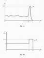
- FIG. 1A exemplarily shows a relationship curve of resistance to which a car door is subjected versus its position, where the horizontal axis represents the position L of the car door (e.g., the distance between the edge of the car door and the door frame of the door body), and the vertical axis represents the resistance f to which the car door is subjected.
- the resistance f remains basically stable.
- the resistance f changes in a sharp peak shape.
- shape of the relationship curve e.g., a peak value f peak of the sharp peak and a position interval ⁇ L (an interval between the position coordinate L 1 and the position coordinate L 2 , etc.)
- ⁇ L an interval between the position coordinate L 1 and the position coordinate L 2 , etc.
- a relationship curve R2 of a balanced driving force versus a position of the car door may be determined from a relationship curve R1 of resistance to which the car door is subjected versus its position, and the balanced driving force may subsequently be adjusted according to the relationship curve R2 such that the balanced driving force applied at each car door position is substantially equivalent to the resistance to which the car door is subjected.
- the adjustment of the balanced driving force to follow the drastically varying resistance f begins only when the car door reaches a position at which its self-locking mechanism starts to act (e.g., position coordinate L 1 in FIG. 1A ).
- the drastic variation of the resistance f within the position interval ⁇ L makes it difficult, and even difficult to achieve, to allow the balanced driving force to follow the resistance.
- the balanced driving force may be made to stepwise jump within the position interval ⁇ L.
- L is the position coordinate of the car door
- F 0 and k are constants greater than 0, where F 0 may for example be taken as the average value of the resistance f to which the car door is subjected within the position interval from 0 to L 1 , and k may be determined for example based on amount of change in the position of the car door during the act of the self-locking mechanism (e.g., the length of the position interval ⁇ L), amount of change in the position of the car door during the application of the balanced driving force (e.g., L 2 ) or the distance traveled and the peak value f peak of the resistance f within the position interval ⁇ L.
- 1B shows a relationship curve of a balanced driving force versus a position of the car door, where the horizontal axis represents the position L of the car door, and the vertical axis represents the balanced driving force F(L) applied to the car door.
- the relationship curve R2 shown follows a pattern of change defined by equation (1).
- the ⁇ in the above equation is a constant greater than 0, which may be determined experimentally.
- the adjustment of the balanced driving force in the manner described above does not precisely follow the change in the resistance force f
- the inventors of the present application have found after research that the effect of the adjustment method described above on the result of the check of the automatic closing function of the landing door is negligible.
- the stepwise jump of the driving force greatly reduces the difficulty of implementation.
- Various means may be used to determine the relationship between the resistance to which the car door is subjected and its position. For example, in some embodiments, it is possible to decouple the car door from the landing door mechanically (i.e., so that the landing door does not move under the drive of the car door), move the car door at a constant speed by controlling a driving force applied by the drive mechanism to the car door, and measure the driving force output by the drive mechanism under the constant-speed movement of the car door, so as to derive the resistance to which the car door is subjected. Subsequently, a relationship curve of resistance to which the car door is subjected versus the position of the car door (e.g., curve R1 shown in FIG.
- a relationship curve of the balanced driving force versus the position of the car door (e.g., curve R2 shown in FIG. 1B ) may be determined therefrom.
- the relationship curve of the balanced driving force versus the position of the car door may be calibrated regularly or irregularly.
- the position of the car door may be determined, for example, by deploying a pair of wireless signal transmitter and wireless signal receiver at the car door and the door frame and measuring the signal strength received by the wireless signal receiver.
- whether the self-locking mechanism of the car door has started to act may be determined based on a variety of signals. These signals include, for example, but are not limited to, a sensing signal from a sensor monitoring a movement of the self-locking mechanism, a current flowing through the self-locking mechanism and a signal from a position feedback device of the self-locking mechanism.
- a sensing signal from a sensor monitoring a movement of the self-locking mechanism a current flowing through the self-locking mechanism and a signal from a position feedback device of the self-locking mechanism.
- this may be determined using a door closing in place signal of the elevator system.
- the above-described preset time period may be determined based on the position and speed of movement of the landing door at the time of starting to apply the balanced driving force.
- the above-described measurement method may be applied to a plurality of positions of the landing door, so as to obtain a calibration relationship between the speed of movement, the position of the landing door at the time of starting to apply the balanced driving force, and the length of time required for the landing door to be completely closed from the beginning of applying the balanced driving force.
- the length of time in the calibration relationship (hereinafter also referred to as the calibration length) may be used to set the preset time period. Specifically, when the check operation of the automatic closing function is performed, the corresponding calibration length is determined as a preset time period from the measurement signals of the position and speed of movement of the landing door at the time when the balanced driving force starts to be applied, utilizing the calibration relationship described above.
- the balanced driving force may be applied at various moments of the closing process of the car door (e.g., at a moment when the car door begins to move or at a moment after the car door begins to move), in some embodiments, applying the balanced driving force at the beginning of the closing process of the landing door is advantageous for simplifying the implementation of the check operation of the automatic closing function.
- the studies of the inventors of the present application have shown that when the moment of application of the balanced driving force is the moment of the beginning of the closing process of the landing door, the initial speed of the landing door shows a high degree of repeatability and the time required for the landing door to reach the completely closed state is also highly consistent. As a result, a preset time period can be determined without measuring the speed and position of the landing door.
- the above-described check operation of the automatic closing function is not only applicable to a single landing door, but is also applicable to a plurality of landing doors.
- the automatic closing function of each landing door may be checked sequentially in the order of the list of landing doors to be maintained in accordance with the above-described checking method, and the checking results is stored, until all the landing doors have completed the check operation.
- the order in which the check is performed may be various specified orders, such as a floor order including landing doors from the 1st floor to the nth floor or landing doors from the nth floor to the 1st floor, or an order obtained by randomly selecting from the landing doors of the 1st to the nth floors.
- the above checking method is also applicable in the case where a floor contains a plurality of landing doors, in which case a corresponding device identification may be assigned to each of the landing doors to distinguish the landing doors from each other.
- the stored checking results may be sent to cloud (e.g., via an IoT gateway to a remote server) or to a mobile terminal (e.g., via a Bluetooth channel or a mobile communication system to a mobile terminal such as a cell phone, a tablet, a portable computer, and a wearable device).
- cloud e.g., via an IoT gateway to a remote server
- mobile terminal e.g., via a Bluetooth channel or a mobile communication system to a mobile terminal such as a cell phone, a tablet, a portable computer, and a wearable device.
- FIG. 2 is a flowchart of a method for detecting an automatic closing function of a landing door of an elevator system in accordance with some embodiments of the present application.
- the method described below may be implemented by various devices, which include, for example, but are not limited to, a control device (e.g., a door controller or an elevator controller) within an elevator system and a dedicated device for detecting an automatic closing function of a landing door, etc., and which are hereinafter collectively referred to as the device or the detection device for detecting the function of the elevator system.
- a control device e.g., a door controller or an elevator controller
- the method shown in FIG. 2 begins at step 201.
- the detection device determines whether the elevator system is suitable for entering the automatic check mode at the current time. If it is suitable for entering the automatic check mode, it proceeds to step 202, otherwise, it continues to wait. Exemplarily, maintenance of the elevator system is usually performed during non-operational period, so the detection device may allow the elevator system to enter the automatic check mode when the current time is outside of the operational hours and there are no calls for the elevator.
- the detection device obtains a queue Q of landing doors to be performed for checking the automatic closing function of the landing door
- the queue comprises one or more landing doors FD i , each landing door being associated with one of a plurality of floors (e.g., provide at an associated floor).
- the order of floors e.g. from the 1 st floor to the nth floor or from the nth floor to the 1 st floor
- the serial number i is used to indicate the order in which the check operation of the automatic closing function of the landing door is performed.
- the detection device also causes the landing door and car door to be in an open state, as shown in FIG. 3A .
- the detection device causes a drive mechanism (e.g., a motor) of the car door CD to start applying the balanced driving force to the car door (e.g., by causing a power source to supply power to the drive mechanism), thereby initiating a closing process of the car door and the ith landing door FD i .
- a driving force greater than the balanced driving force F 0 may be applied during a short time interval (e.g. a few hundred milliseconds) at the beginning of the closing process to cause the car door drive the landing door to start moving, and subsequently to drive the car door CD with the balanced driving force F 0 .
- the driving force applied during the time interval at the beginning is not equal to the balanced driving force, it is reasonable to consider the balanced driving force as applied at the beginning of the closing process due to the short time interval.
- the gap of the landing door FD i is continuously decreasing, as shown in FIG. 3B .
- step 205 the detection device will determine a reference value or a preset time period for determining whether the automatic closing function is normal.
- the balanced driving force may be applied at various moments of the closing process of the car door. If the balanced driving force is applied at the beginning of the closing process, the preset time period may be determined without measuring the speed and position of the landing door. On the other hand, if the balanced driving force is applied to the car door during the closing process, the corresponding calibration length is determined as a preset time period from the position and speed of movement of the landing door measured at the time when the balanced driving force starts to be applied by utilizing a predetermined calibration relationship.
- the detection device determines whether the car door reaches a position (e.g., the position coordinate L 1 in FIG. 1A ) at which its self-locking mechanism starts to act, for example, based on one or more of a sensing signal from a sensor monitoring a movement of the self-locking mechanism, a current flowing through the self-locking mechanism and a signal from a position feedback device of the self-locking mechanism. If the car door reaches the position, proceed to step 207, otherwise it continues to determine whether the car door reaches the position.
- a position e.g., the position coordinate L 1 in FIG. 1A
- step 207 the detection device begins to adjust the balanced driving force.
- the adjustment method has been described above and will not be repeated here.
- step 208 the detection device determines whether the automatic closing function of the landing door FD i is normal based on the closing behavior of the landing door FD i . Specifically, if the landing door FD i can be closed normally (e.g., as shown in FIG. 3C ) within a preset time period since the start of applying the balanced driving force to the car door CD, it is determined that the automatic closing function of the landing door FD i is normal, otherwise, it is determined that the automatic closing function of the landing door FD i is abnormal. Exemplarily, it may be determined whether the landing door FD i is closed completely with the aid of the door closing in place signal of the elevator system.
- the landing door FD i is closed completely with the aid of the door closing in place signal of the elevator system.
- step 209 in which the detection device stores the checking result regarding the automatic closing function of the landing door FD i .
- step 210 the detection device determines whether the checking of the automatic closing function of the landing door has been completed for all landing doors in the queue Q. If all landing doors in the queue Q are traversed, it proceeds to step 211, and otherwise, it proceeds to step 212.
- the detection device sends the checking results regarding the automatic closing function of each landing door stored in step 209 to the cloud or the mobile terminal.
- the method flow shown in FIG. 2 returns to step 203 so as to perform the check operation of the automatic closing function of the landing door for other landing doors in the queue Q.
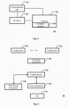
- FIG. 4 is a schematic block diagram of a device or detection device for detecting an automatic closing function of a landing door of an elevator system in accordance with some other embodiments of the present application.
- the detection device shown in FIG. 4 may be used to implement the method shown in FIG. 2 .
- a detection device 40 comprises a communication unit 410, a memory 420 (e.g., a non-volatile memory such as a flash memory, a ROM, a hard drive, a disk, an optical disc), a processor 430, and a computer program 440.
- a memory 420 e.g., a non-volatile memory such as a flash memory, a ROM, a hard drive, a disk, an optical disc
- a processor 430 e.g., a processor 430
- a computer program 440 e.g., a computer program 440.
- the communication unit 410 serves as a communication interface configured to establish a communication connection between the detection device and an external device (e.g., a drive mechanism of a car door, a sensor that monitors the movement or current of a self-locking mechanism, a position feedback device of the self-locking mechanism, etc.) or a network (e.g., Internet and a wireless local area network, etc.).
- an external device e.g., a drive mechanism of a car door, a sensor that monitors the movement or current of a self-locking mechanism, a position feedback device of the self-locking mechanism, etc.
- a network e.g., Internet and a wireless local area network, etc.
- the memory 420 stores the computer program 440 that may be executed by the processor 430.
- the memory 420 may store data generated by the processor 430 in execution of the computer program 440 and data received from the external device via the communication unit 410 (e.g., a queue Q of landing doors to be performed for checking the automatic closing function and a checking result regarding the automatic closing function, etc.).
- the processor 430 is configured to run the computer program 440 stored on the memory 420 and to perform access operations to the memory 420 (e.g., obtaining the queue Q of landing doors and storing the checking result regarding the automatic closing function in the memory 420).
- the computer program 440 may include computer instructions for implementing a method described with the aid of FIG. 2 , enabling implementation of the corresponding method when the computer program 440 is run on the processor 430.
- FIG. 5 is a schematic block diagram of an elevator system in accordance with some other embodiments of the present application.
- An elevator system 50 shown in FIG. 5 includes landing doors FD 1 to FD n provided at a plurality of floors having an automatic closing function of a landing door, a car CD, a drive mechanism 510 for driving the movement of the car, a self-locking mechanism 520 of the car door, an executing mechanism 530 for implementing the automatic closing function of the landing door, and a control device (e.g., a door controller or an elevator controller) 540.
- a control device e.g., a door controller or an elevator controller
- control device is coupled with the drive mechanism 510, the self-locking mechanism 520, which has one or more features of the detection device shown in FIG. 4 , so as to perform the check operation of the automatic closing function of the landing door described in detail above.
Landscapes
- Engineering & Computer Science (AREA)
- Automation & Control Theory (AREA)
- Elevator Door Apparatuses (AREA)
Abstract
The present application relates to elevator maintenance technology and, in particular, to a method and device for detecting an automatic closing function of a landing door, an elevator system comprising the device, and a non-transitory computer-readable storage medium storing a computer program for implementing the method. In the method for detecting the automatic closing function of the landing door in accordance with an aspect of the present application, when a car of an elevator system stops at one of a plurality of floors, a car door of the car and a landing door associated with one of the plurality of floors are opened. Subsequently, during a closing process of the landing door, a drive mechanism of the elevator system is caused to apply a balanced driving force to the car door of the car. The balanced driving force corresponds to resistance to which the car door is subjected. Next, it is determined whether the associated landing door can be closed normally within a preset time period since the start of applying the balanced driving force to the car door.
Description
- The present application relates to elevator maintenance technology and, in particular, to a method and device for detecting an automatic closing function of a landing door, an elevator system comprising the device, and a non-transitory computer-readable storage medium storing a computer program for implementing the method.
- When an elevator car is running or a landing door is not properly closed, the landing door will be locked or closed automatically with the help of a self-locking function or an automatic closing function to reduce the risk of accidents. Currently, the check of the automatic closing function of the landing door is still manually completed. For example, maintenance personnel regularly or irregularly test the automatic closing function of the landing door on each floor one by one to determine whether its function is normal. The check work will take a large amount of labor and time, especially for elevator systems operating in high-rise and ultra-high-rise buildings.
- In accordance with an aspect of the present application, there is provided a method for detecting an automatic closing function of a landing door. In the method for detecting the automatic closing function of the landing door in accordance with an aspect of the present application, when a car of an elevator system stops at one of a plurality of floors, a car door of the car and a landing door associated with one of the plurality of floors are opened. Subsequently, during a closing process of the landing door, a drive mechanism of the elevator system is caused to apply a balanced driving force to the car door of the car. The balanced driving force corresponds to resistance to which the car door is subjected. Next, it is determined whether the associated landing door can be closed normally within a preset time period since the start of applying the balanced driving force to the car door.
- Particular embodiments further may include at least one, or a plurality of, the following optional features, alone or in combination with each other:
Optionally, the method performs the above steps in a specified order for landing doors associated with one or more other floors of the plurality of floors. - Optionally, the method further comprises sending a detection report on the automatic closing function of the landing door of the one or more landing floors to cloud or a mobile terminal.
- Optionally, in the method, further comprising: determining whether the elevator system is adapted to enter or be in a test mode, and if so, performing the above steps.
- Optionally, the balanced driving force is adjusted based on a position of the car door during an application of the balanced driving force to the car door. Further, the balanced driving force is adjusted only after the car door reaches a position at which its self-locking mechanism starts to act. Still further, the balanced driving force is adjusted in such a way that the balanced driving force makes a stepwise jump, magnitude of the jump being determined based on amount of change in the position of the car door and peak value of the resistance to which the car door is subjected during the act of the self-locking mechanism, amount of change in the position of the car door during the application of the balanced driving force.
- Optionally, in the method, further comprising: obtaining a relationship curve between the balanced driving force and the position of the car door. Further, the relationship curve may be determined in the following manner: decoupling the car door from the landing door mechanically and causing the car door to move at a constant speed by controlling a driving force applied by the drive mechanism to the car door, and subsequently obtaining the relationship curve based on the applied driving force and the corresponding position of the car door. Furthermore, the relationship curve may be calibrated regularly or irregularly.
- Optionally, determining whether the self-locking mechanism starts to act is based on at least one of: a sensing signal from a sensor monitoring a movement of the self-locking mechanism, a current flowing through the self-locking mechanism and a signal from a position feedback device of the self-locking mechanism.
- Optionally, the preset time period is determined based on speed of movement and position of the landing door at the beginning of applying the balanced driving force.
- Optionally, the balanced driving force is applied from the start of the closing process or from a moment after the start of the closing process.
- A device for detecting an automatic closing function of a landing door of an elevator system in accordance with another aspect of the present application comprises a memory, a processor coupled with the memory, and a computer program stored on the memory and running on the processor. The running of the computer program results in the following operations: opening a car door of the car and a landing door associated with one of the plurality of floors when a car of the elevator system stops at one of a plurality of floors; causing a drive mechanism of the elevator system to apply a balanced driving force to the car door of the car during a closing process of the landing door, wherein the balanced driving force corresponds to resistance to which the car door is subjected; and determining whether the associated landing door can be closed normally within a preset time period since the start of applying the balanced driving force to the car door.
- Particular embodiments further may include at least one, or a plurality of, the above optional features, alone or in combination with each other:
An elevator system in accordance with another aspect of the present application comprises: landing doors provided at a plurality of floors, a car, a drive mechanism and a control device. The landing door has an automatic closing function. The control device comprises a memory, a processor coupled with the memory, and a computer program stored on the memory and running on the processor. The running of the computer program results in the following operations: opening a car door of the car and a landing door associated with one of the plurality of floors when a car of the elevator system stops at one of a plurality of floors; causing a drive mechanism of the elevator system to apply a balanced driving force to the car door of the car during a closing process of the landing door, wherein the balanced driving force corresponds to resistance to which the car door is subjected; and determining whether the associated landing door can be closed normally within a preset time period since the start of applying the balanced driving force to the car door. - Particular embodiments further may include at least one, or a plurality of, the above optional features, alone or in combination with each other:
In accordance with a further aspect of the present application, there is provided a computer-readable storage medium on which a computer program suitable for running on a processor of a terminal device is stored, the running of the computer program resulting in the steps of the method as described above being performed. - The above and/or other aspects and advantages of the present application will be clearer and more easily understood from the following description of various aspects in conjunction with the accompanying drawings, in which the same or similar units are denoted by the same reference numerals. The accompanying drawings include:
-
FIG. 1A exemplarily shows a relationship curve of resistance to which a car door is subjected versus its position. -
FIG. 1B exemplarily shows a relationship curve of a balanced driving force applied to a car door versus a position of the car door. -
FIG. 2 is a flowchart of a method for detecting a function of an elevator system in accordance with some embodiments of the present application. -
FIGS. 3A-3C are schematic diagrams of states of a car door and a landing door of an elevator system. -
FIG. 4 is a schematic block diagram of a device or detection device for detecting a function of an elevator system in accordance with some other embodiments of the present application. -
FIG. 5 is a schematic block diagram of an elevator system in accordance with some other embodiments of the present application. - The present application is described more fully below with reference to the accompanying drawings, in which illustrative embodiments of the application are illustrated. However, the present application may be implemented in different forms and should not be construed as limited to the embodiments presented herein. The presented embodiments are intended to make the disclosure herein comprehensive and complete, so as to more comprehensively convey the protection scope of the application to those skilled in the art.
- In this specification, terms such as "comprising" and "including" mean that in addition to units and steps that are directly and clearly stated in the specification and claims, the technical solution of the application does not exclude the presence of other units and steps that are not directly or clearly stated in the specification and claims.
- In this specification, "closing process" refers to a process in which a car door or landing door begins to move until it is normally closed or reaches a closed state. During the closing process, the car door or landing door gradually decreases a gap between the doors. The normal closing or closed state described herein means that the car door or landing door is completely closed without gaps or openings. It is noted that the gap described herein may refer to a gap between door bodies (when the door comprises a plurality of door bodies) or a gap between the door body and the door frame (when the door comprises only one door body).
- In this specification, "automatic closing function of a landing door" refers to a function that causes the landing door to close, prohibits the opening of the landing door, or locks the landing door when an elevator system is in a specific state (e.g., when the car is in the stopped state and the landing door is completely closed). It should be noted that the implementation of the automatic closing function of the landing door is dependent on a cooperative operation of multiple levels and multiple components. For example, in the case of the landing door of the elevator system, a control device (e.g., a door controller or elevator controller) monitors the state of each landing door and the position of the car, and determines the timing of locking the landing door based on the monitoring information; for example, the door sensor or door lock switch is responsible for transmitting the state signal of the landing door (e.g., a door closing in place signal) to the control device; and for example, an executing mechanism is a key component that usually executes actions to close, lock, or unlock the landing door based on instructions from the control device. That is, any abnormal operation of any level or component may lead to an abnormal automatic closing function of the landing door.
- The specific structure and working principle of the executing mechanism may vary depending on the elevator manufacturer and product model, and the executing mechanism usually includes components such as a spring device and/or a saftey gear for ensuring normal operation of the self-locking function or the automatic closing function. For example, in a typical executing mechanism, when the landing door is in a closed state, the spring will apply a certain force to the landing door to drive it into a completely closed state and keep it tightly closed. The saftey gear is another component of the executing mechanism, which may drive the landing door into a completely closed state and keep it locked when the car is in a stopped state. It should be noted that it is usually not necessary to configure a separate saftey gear for each landing door; furthermore, a separate spring may be configured for each landing door, or a shared set of spring systems may be used to support multiple landing doors of the elevator system.
- In some embodiments of the present application, a check of the automatic closing function of the landing door will be performed by causing the elevator system to enter an automatic check mode. The check of the automatic closing function of the landing door is described in detail below.
- During a period when the elevator system is idle (e.g., a non-operational period), the car door is driven into a closing process. During the closing process, the landing door moves in the same direction under the drive of the car door. A drive mechanism such as an electric motor or hydraulic system may usually be used to provide the force or driving force used to drive the movement of the car door and the landing door. In addition to the driving force from the drive mechanism, the force applied to the landing door by the executing mechanism described above also plays an auxiliary role in the closing of the landing door. When the combined force of the driving force and the auxiliary force is large enough to overcome the resistance to which the car door and the landing door are subjected (e.g. the friction between the car door and the landing door and the door frame), the car door and the landing door are closed. As the car door and the landing door move, the gap of the car door and the gap of the landing door will be gradually reduced until it is completely closed or closed. Therefore, it may be determined whether the automatic closing function of the landing door is normal based on the result of whether the landing door is able to close completely or normally (the result may be obtained, for example, by a door closing in place signal).
- In some embodiments, the magnitude of the driving force may be selected such that it corresponds to or is substantially equivalent to the resistance to which the car door is subjected (hereinafter, the driving force corresponding to the resistance to which the car door is subjected is referred to as the balanced driving force). When the balanced driving force is utilized to drive the car door, the external force to which the landing door is subjected is the combined force of the auxiliary force applied by the executing mechanism and the resistance to which the landing door is subjected; in such a case, if the automatic closing function of the landing door is normal, the landing door will ultimately enter into a completely closed or closed state, otherwise, the landing door will not be closed normally or enter into a completely closed state, whereby it may be judged based on the above result whether the automatic closing function of the landing door is normal. "Corresponding" and "substantially equivalent" as described herein means that the balanced driving force may take a value within a certain range near the resistance, as long as the deviation of this value from the resistance does not materially affect the result of the check of the automatic closing function of the landing door.
- In some cases, the resistance to which the car door is subjected varies with its position.
FIG. 1A exemplarily shows a relationship curve of resistance to which a car door is subjected versus its position, where the horizontal axis represents the position L of the car door (e.g., the distance between the edge of the car door and the door frame of the door body), and the vertical axis represents the resistance f to which the car door is subjected. As shown inFiG. 1A , during the movement of the car door from the zero point of the position coordinate (corresponding to the beginning of the closing process or the moment when the car door is completely open) to the position coordinate L1 (corresponding to the beginning of the action of the self-locking mechanism of the car door), the resistance f remains basically stable. During the movement of the car door from the position coordinate L1 to the position coordinate L2 (corresponding to the moment when the car door is in the completely closed state), the resistance f changes in a sharp peak shape. Although the shape of the relationship curve (e.g., a peak value fpeak of the sharp peak and a position interval ΔL (an interval between the position coordinate L1 and the position coordinate L2, etc.)) varies with the structure and working principle of the self-locking mechanism of the car door as well as with the environment in which the elevator system is applied, etc., this pattern of change in the resistance is similar. - In some embodiments, a relationship curve R2 of a balanced driving force versus a position of the car door may be determined from a relationship curve R1 of resistance to which the car door is subjected versus its position, and the balanced driving force may subsequently be adjusted according to the relationship curve R2 such that the balanced driving force applied at each car door position is substantially equivalent to the resistance to which the car door is subjected.
- In some embodiments, the adjustment of the balanced driving force to follow the drastically varying resistance f begins only when the car door reaches a position at which its self-locking mechanism starts to act (e.g., position coordinate L1 in
FIG. 1A ). However, the drastic variation of the resistance f within the position interval ΔL makes it difficult, and even difficult to achieve, to allow the balanced driving force to follow the resistance. For this reason, in some embodiments, the balanced driving force may be made to stepwise jump within the position interval ΔL. Exemplarily, the balanced driving force F(L) may be determined by the following equation:
- In the above equation, L is the position coordinate of the car door, F0 and k are constants greater than 0, where F0 may for example be taken as the average value of the resistance f to which the car door is subjected within the position interval from 0 to L1, and k may be determined for example based on amount of change in the position of the car door during the act of the self-locking mechanism (e.g., the length of the position interval ΔL), amount of change in the position of the car door during the application of the balanced driving force (e.g., L2) or the distance traveled and the peak value fpeak of the resistance f within the position interval ΔL.
FIG. 1B shows a relationship curve of a balanced driving force versus a position of the car door, where the horizontal axis represents the position L of the car door, and the vertical axis represents the balanced driving force F(L) applied to the car door. Referring toFIG. 1B , the relationship curve R2 shown follows a pattern of change defined by equation (1). - Exemplarily, the value of k may be determined using the following equation:

- The α in the above equation is a constant greater than 0, which may be determined experimentally.
- Although the adjustment of the balanced driving force in the manner described above does not precisely follow the change in the resistance force f, the inventors of the present application have found after research that the effect of the adjustment method described above on the result of the check of the automatic closing function of the landing door is negligible. In addition, in the case of a drive mechanism such as a motor, the stepwise jump of the driving force greatly reduces the difficulty of implementation.
- Various means may be used to determine the relationship between the resistance to which the car door is subjected and its position. For example, in some embodiments, it is possible to decouple the car door from the landing door mechanically (i.e., so that the landing door does not move under the drive of the car door), move the car door at a constant speed by controlling a driving force applied by the drive mechanism to the car door, and measure the driving force output by the drive mechanism under the constant-speed movement of the car door, so as to derive the resistance to which the car door is subjected. Subsequently, a relationship curve of resistance to which the car door is subjected versus the position of the car door (e.g., curve R1 shown in
FIG. 1A ) may be generated based on the applied driving force and the corresponding position of the car door, and a relationship curve of the balanced driving force versus the position of the car door (e.g., curve R2 shown inFIG. 1B ) may be determined therefrom. In other embodiments, the relationship curve of the balanced driving force versus the position of the car door may be calibrated regularly or irregularly. - The position of the car door may be determined, for example, by deploying a pair of wireless signal transmitter and wireless signal receiver at the car door and the door frame and measuring the signal strength received by the wireless signal receiver. In addition, whether the self-locking mechanism of the car door has started to act may be determined based on a variety of signals. These signals include, for example, but are not limited to, a sensing signal from a sensor monitoring a movement of the self-locking mechanism, a current flowing through the self-locking mechanism and a signal from a position feedback device of the self-locking mechanism. As for the determination that the car door is in a completely closed state, this may be determined using a door closing in place signal of the elevator system.
- It is generally recognized that an abnormality in the automatic closing function, regardless of the cause, results in the landing door not being able to close completely. However, even if the landing door is able to close completely, it cannot be ruled out that the automatic closing function may fail within a short period of time. In order to be able to detect such a potential risk of failure, in some embodiments of the present application, not only attention is paid to the ability of the landing door to be completely closed, but also time is introduced as a dimension to be examined, i.e., it is determined that the automatic closing function of the landing door is normal only if the landing door is able to enter a closed state within a preset time period since the start of outputting the balanced driving force by the drive mechanism.
- The above-described preset time period may be determined based on the position and speed of movement of the landing door at the time of starting to apply the balanced driving force. In some embodiments, it is possible, for example, to couple the car door to the landing door (i.e., to cause the landing door to move under the drive of the car door), to drive the car door with the balanced driving force when the landing door reaches a certain position, and to measure the speed of movement of the landing door at this time (e.g., by using a speed sensor arranged on the landing door), the position (e.g., by means of the signal strength-based method as described above), and a length of time required for the landing door to be normally closed or completely closed from the beginning of applying the balanced driving force, provided that it has been verified that the automatic closing function of the landing door is normal. The above-described measurement method may be applied to a plurality of positions of the landing door, so as to obtain a calibration relationship between the speed of movement, the position of the landing door at the time of starting to apply the balanced driving force, and the length of time required for the landing door to be completely closed from the beginning of applying the balanced driving force. The length of time in the calibration relationship (hereinafter also referred to as the calibration length) may be used to set the preset time period. Specifically, when the check operation of the automatic closing function is performed, the corresponding calibration length is determined as a preset time period from the measurement signals of the position and speed of movement of the landing door at the time when the balanced driving force starts to be applied, utilizing the calibration relationship described above.
- Although the balanced driving force may be applied at various moments of the closing process of the car door (e.g., at a moment when the car door begins to move or at a moment after the car door begins to move), in some embodiments, applying the balanced driving force at the beginning of the closing process of the landing door is advantageous for simplifying the implementation of the check operation of the automatic closing function. In particular, the studies of the inventors of the present application have shown that when the moment of application of the balanced driving force is the moment of the beginning of the closing process of the landing door, the initial speed of the landing door shows a high degree of repeatability and the time required for the landing door to reach the completely closed state is also highly consistent. As a result, a preset time period can be determined without measuring the speed and position of the landing door.
- The above-described check operation of the automatic closing function is not only applicable to a single landing door, but is also applicable to a plurality of landing doors. For example, the automatic closing function of each landing door may be checked sequentially in the order of the list of landing doors to be maintained in accordance with the above-described checking method, and the checking results is stored, until all the landing doors have completed the check operation. It is to be noted that the order in which the check is performed may be various specified orders, such as a floor order including landing doors from the 1st floor to the nth floor or landing doors from the nth floor to the 1st floor, or an order obtained by randomly selecting from the landing doors of the 1st to the nth floors. In addition, the above checking method is also applicable in the case where a floor contains a plurality of landing doors, in which case a corresponding device identification may be assigned to each of the landing doors to distinguish the landing doors from each other.
- In some embodiments, the stored checking results may be sent to cloud (e.g., via an IoT gateway to a remote server) or to a mobile terminal (e.g., via a Bluetooth channel or a mobile communication system to a mobile terminal such as a cell phone, a tablet, a portable computer, and a wearable device).
-
FIG. 2 is a flowchart of a method for detecting an automatic closing function of a landing door of an elevator system in accordance with some embodiments of the present application. The method described below may be implemented by various devices, which include, for example, but are not limited to, a control device (e.g., a door controller or an elevator controller) within an elevator system and a dedicated device for detecting an automatic closing function of a landing door, etc., and which are hereinafter collectively referred to as the device or the detection device for detecting the function of the elevator system. - The method shown in
FIG. 2 begins atstep 201. In this step, the detection device determines whether the elevator system is suitable for entering the automatic check mode at the current time. If it is suitable for entering the automatic check mode, it proceeds to step 202, otherwise, it continues to wait. Exemplarily, maintenance of the elevator system is usually performed during non-operational period, so the detection device may allow the elevator system to enter the automatic check mode when the current time is outside of the operational hours and there are no calls for the elevator. - At
step 202, the detection device obtains a queue Q of landing doors to be performed for checking the automatic closing function of the landing door, the queue comprises one or more landing doors FDi, each landing door being associated with one of a plurality of floors (e.g., provide at an associated floor). In some embodiments, the order of floors (e.g. from the 1 st floor to the nth floor or from the nth floor to the 1 st floor) is used as the order in which checks are performed on the landing doors. However, it should be noted that this is not necessary and other checking orders may be used as needed for application scenarios (e.g., performing the checking only for landing doors on even or odd numbered floors, or performing the checking for landing doors that are used frequently). Exemplarily, the serial number i is used to indicate the order in which the check operation of the automatic closing function of the landing door is performed. - Then proceed to step 203, in which the detection device causes the car to stop at the floor associated with the ith landing door FDi (i=1 when the detection is started) in the queue Q of landing doors, i.e., the car stops stationary at that floor. Optionally, the detection device also causes the landing door and car door to be in an open state, as shown in
FIG. 3A . - Next, at
step 204, the detection device causes a drive mechanism (e.g., a motor) of the car door CD to start applying the balanced driving force to the car door (e.g., by causing a power source to supply power to the drive mechanism), thereby initiating a closing process of the car door and the ith landing door FDi. In practice, a driving force greater than the balanced driving force F0 may be applied during a short time interval (e.g. a few hundred milliseconds) at the beginning of the closing process to cause the car door drive the landing door to start moving, and subsequently to drive the car door CD with the balanced driving force F0. Although the driving force applied during the time interval at the beginning is not equal to the balanced driving force, it is reasonable to consider the balanced driving force as applied at the beginning of the closing process due to the short time interval. During the application of the balanced driving force F0 to the car door CD, the gap of the landing door FDi is continuously decreasing, as shown inFIG. 3B . - Then proceed to step 205, in which the detection device will determine a reference value or a preset time period for determining whether the automatic closing function is normal. As described above, the balanced driving force may be applied at various moments of the closing process of the car door. If the balanced driving force is applied at the beginning of the closing process, the preset time period may be determined without measuring the speed and position of the landing door. On the other hand, if the balanced driving force is applied to the car door during the closing process, the corresponding calibration length is determined as a preset time period from the position and speed of movement of the landing door measured at the time when the balanced driving force starts to be applied by utilizing a predetermined calibration relationship.
- In
step 206, the detection device determines whether the car door reaches a position (e.g., the position coordinate L1 inFIG. 1A ) at which its self-locking mechanism starts to act, for example, based on one or more of a sensing signal from a sensor monitoring a movement of the self-locking mechanism, a current flowing through the self-locking mechanism and a signal from a position feedback device of the self-locking mechanism. If the car door reaches the position, proceed to step 207, otherwise it continues to determine whether the car door reaches the position. - In
step 207, the detection device begins to adjust the balanced driving force. The adjustment method has been described above and will not be repeated here. - The process shown in
FIG. 2 proceeds to step 208 afterstep 207. In this step, the detection device determines whether the automatic closing function of the landing door FDi is normal based on the closing behavior of the landing door FDi. Specifically, if the landing door FDi can be closed normally (e.g., as shown inFIG. 3C ) within a preset time period since the start of applying the balanced driving force to the car door CD, it is determined that the automatic closing function of the landing door FDi is normal, otherwise, it is determined that the automatic closing function of the landing door FDi is abnormal. Exemplarily, it may be determined whether the landing door FDi is closed completely with the aid of the door closing in place signal of the elevator system. - Then proceed to step 209, in which the detection device stores the checking result regarding the automatic closing function of the landing door FDi.
- Subsequently, in
step 210, the detection device determines whether the checking of the automatic closing function of the landing door has been completed for all landing doors in the queue Q. If all landing doors in the queue Q are traversed, it proceeds to step 211, and otherwise, it proceeds to step 212. - At
step 211, the detection device sends the checking results regarding the automatic closing function of each landing door stored instep 209 to the cloud or the mobile terminal. - At
step 212, the detection device increments the serial number of the landing door (i=i+1) to cause the operation object of the subsequent step to be updated to the next landing door in the queue Q. After completingstep 212, the method flow shown inFIG. 2 returns to step 203 so as to perform the check operation of the automatic closing function of the landing door for other landing doors in the queue Q. -
FIG. 4 is a schematic block diagram of a device or detection device for detecting an automatic closing function of a landing door of an elevator system in accordance with some other embodiments of the present application. The detection device shown inFIG. 4 may be used to implement the method shown inFIG. 2 . - As shown in
FIG. 4 , a detection device 40 comprises acommunication unit 410, a memory 420 (e.g., a non-volatile memory such as a flash memory, a ROM, a hard drive, a disk, an optical disc), aprocessor 430, and acomputer program 440. - The
communication unit 410 serves as a communication interface configured to establish a communication connection between the detection device and an external device (e.g., a drive mechanism of a car door, a sensor that monitors the movement or current of a self-locking mechanism, a position feedback device of the self-locking mechanism, etc.) or a network (e.g., Internet and a wireless local area network, etc.). - The
memory 420 stores thecomputer program 440 that may be executed by theprocessor 430. In addition, thememory 420 may store data generated by theprocessor 430 in execution of thecomputer program 440 and data received from the external device via the communication unit 410 (e.g., a queue Q of landing doors to be performed for checking the automatic closing function and a checking result regarding the automatic closing function, etc.). - The
processor 430 is configured to run thecomputer program 440 stored on thememory 420 and to perform access operations to the memory 420 (e.g., obtaining the queue Q of landing doors and storing the checking result regarding the automatic closing function in the memory 420). - The
computer program 440 may include computer instructions for implementing a method described with the aid ofFIG. 2 , enabling implementation of the corresponding method when thecomputer program 440 is run on theprocessor 430. -
FIG. 5 is a schematic block diagram of an elevator system in accordance with some other embodiments of the present application. - An
elevator system 50 shown inFIG. 5 includes landing doors FD1 to FDn provided at a plurality of floors having an automatic closing function of a landing door, a car CD, adrive mechanism 510 for driving the movement of the car, a self-lockingmechanism 520 of the car door, an executingmechanism 530 for implementing the automatic closing function of the landing door, and a control device (e.g., a door controller or an elevator controller) 540. - Referring to
FIG. 5 , the control device is coupled with thedrive mechanism 510, the self-lockingmechanism 520, which has one or more features of the detection device shown inFIG. 4 , so as to perform the check operation of the automatic closing function of the landing door described in detail above. - Those skilled in the art will appreciate that various illustrative logical blocks, modules, circuits, and algorithm steps described herein may be implemented as electronic hardware, computer software, or combinations of both.
- To demonstrate this interchangeability between the hardware and software, various illustrative components, blocks, modules, circuits, and steps have been described above generally in terms of their functionality. Whether such functionality is implemented in hardware or software depends on the particular application and design constraints imposed on the overall system. Those skilled in the art may implement the described functionality in changing ways for the particular application. However, such implementation decisions should not be interpreted as causing a departure from the scope of the present application.
- Although only a few of the specific embodiments of the present application have been described, those skilled in the art will appreciate that the present application may be embodied in many other forms without departing from the spirit and scope thereof. Accordingly, the examples and implementations shown are to be regarded as illustrative and not restrictive, and various modifications and substitutions may be covered by the application without departing from the spirit and scope of the application as defined by the appended claims.
- The embodiments and examples presented herein are provided to best illustrate embodiments in accordance with the present technology and its particular application, and to thereby enable those skilled in the art to implement and use the present application. However, those skilled in the art will appreciate that the above description and examples are provided for convenience of illustration and example only. The presented description is not intended to cover every aspect of the application or to limit the application to the precise form disclosed.
Claims (15)
- A method for detecting an automatic closing function of a landing door, the method comprising:A. when a car of an elevator system stops at one of a plurality of floors, opening a car door of the car and a landing door associated with one of the plurality of floors;B. causing a drive mechanism of the elevator system to apply a balanced driving force to the car door of the car during a closing process of the landing door, wherein the balanced driving force corresponds to resistance to which the car door is subjected; andC. determining whether the associated landing door can be closed normally within a preset time period since starting to apply the balanced driving force to the car door.
- The method of claim 1, further comprising: performing steps A-C in a specified order for landing doors associated with one or more other floors of the plurality of floors.
- The method of claim 1 or 2, further comprising: sending a detection report on the automatic closing function of the landing door of the one or more landing floors to cloud or a mobile terminal.
- The method of any one of claims 1 to 3, further comprising: determining whether the elevator system is adapted to enter or be in a test mode, and if so, performing the steps in the method as claimed in any one of claims 1 to 3.
- The method of any one of claims 1 to 4, wherein the balanced driving force is adjusted based on a position of the car door during applying the balanced driving force to the car door.
- The method of claim 5, wherein the balanced driving force is adjusted only after the car door reaches a position at which its self-locking mechanism starts to act.
- The method of claim 6, wherein the balanced driving force is adjusted in such a way that the balanced driving force makes a stepwise jump, magnitude of the jump being determined based on amount of change in the position of the car door and peak value of the resistance to which the car door is subjected during the acting of the self-locking mechanism, amount of change in the position of the car door during applying the balanced driving force.
- The method of any one of claims 1 to 7, further comprising: obtaining a relationship curve between the balanced driving force and the position of the car door.
- The method of claim 8, wherein the relationship curve is determined in the following manner:decoupling the car door from the landing door mechanically;causing the car door to move at a constant speed by controlling a driving force applied by the drive mechanism to the car door; andobtaining the relationship curve based on the applied driving force and the corresponding position of the car door.
- The method of claim 8 or 9, wherein the relationship curve is calibrated regularly or irregularly.
- The method of any one of claims 1 to 10, wherein determining whether the self-locking mechanism starts to act is based on at least one of: a sensing signal from a sensor monitoring a movement of the self-locking mechanism, a current flowing through the self-locking mechanism and a signal from a position feedback device of the self-locking mechanism; and/orwherein the preset time period is determined based on speed of movement and position of the landing door at the beginning of applying the balanced driving force; and/orwherein the balanced driving force is applied from the start of the closing process or from a moment after the start of the closing process.
- A device for detecting an automatic closing function of a landing door of an elevator system, the device comprising:a memory;a processor coupled with the memory; anda computer program stored on the memory and running on the processor, the running of the computer program resulting in carrying out the method of any one of claims 1 to 11.
- The device of claim 12, wherein the device is a door controller or an elevator controller.
- An elevator system comprising:landing doors provided at a plurality of floors having an automatic closing function of a landing door;a car;a drive mechanism; anda control device comprising:a memory;a processor coupled with the memory; anda computer program stored on the memory and running on the processor, the running of the computer program resulting in carrying out the method of any one of claims 1 to 11.
- A non-transitory computer-readable storage medium, the computer-readable storage medium having instructions stored therein, characterized in that when the instructions are executed by a processor, the processor performs the method of any one of claims 1 to 11.
Applications Claiming Priority (1)
| Application Number | Priority Date | Filing Date | Title |
|---|---|---|---|
| CN202311455861.4A CN119929612A (en) | 2023-11-02 | 2023-11-02 | Method and device for detecting automatic closing function of landing door |
Publications (1)
| Publication Number | Publication Date |
|---|---|
| EP4549357A1 true EP4549357A1 (en) | 2025-05-07 |
Family
ID=93333599
Family Applications (1)
| Application Number | Title | Priority Date | Filing Date |
|---|---|---|---|
| EP24209631.1A Pending EP4549357A1 (en) | 2023-11-02 | 2024-10-29 | Method and device for detecting automatic closing function of landing door |
Country Status (3)
| Country | Link |
|---|---|
| US (1) | US20250145415A1 (en) |
| EP (1) | EP4549357A1 (en) |
| CN (1) | CN119929612A (en) |
Citations (3)
| Publication number | Priority date | Publication date | Assignee | Title |
|---|---|---|---|---|
| JP2010280495A (en) * | 2009-06-08 | 2010-12-16 | Mitsubishi Electric Corp | Elevator door inspection device and door inspection method |
| US20160009528A1 (en) * | 2013-03-12 | 2016-01-14 | Mitsubishi Electric Corporation | Elevator door control device |
| WO2023020693A1 (en) * | 2021-08-19 | 2023-02-23 | Kone Corporation | Monitoring elevator door operation |
-
2023
- 2023-11-02 CN CN202311455861.4A patent/CN119929612A/en active Pending
-
2024
- 2024-10-29 EP EP24209631.1A patent/EP4549357A1/en active Pending
- 2024-10-29 US US18/929,802 patent/US20250145415A1/en active Pending
Patent Citations (3)
| Publication number | Priority date | Publication date | Assignee | Title |
|---|---|---|---|---|
| JP2010280495A (en) * | 2009-06-08 | 2010-12-16 | Mitsubishi Electric Corp | Elevator door inspection device and door inspection method |
| US20160009528A1 (en) * | 2013-03-12 | 2016-01-14 | Mitsubishi Electric Corporation | Elevator door control device |
| WO2023020693A1 (en) * | 2021-08-19 | 2023-02-23 | Kone Corporation | Monitoring elevator door operation |
Also Published As
| Publication number | Publication date |
|---|---|
| US20250145415A1 (en) | 2025-05-08 |
| CN119929612A (en) | 2025-05-06 |
Similar Documents
| Publication | Publication Date | Title |
|---|---|---|
| KR102561105B1 (en) | Elevarot sensor calibration | |
| CN109205424B (en) | Elevator sensor system calibration | |
| CN110921449B (en) | Sensor-based shutdown detection for elevator systems | |
| CN108689268A (en) | Automated testing method and elevator brake for elevator safety brake system test system | |
| EP2489621A1 (en) | A method for determining and displaying a floor level indication. | |
| JP2008230742A (en) | Maintenance control system of elevator | |
| CN110407048A (en) | The operation monitoring system of elevator | |
| KR20190005758A (en) | Elevator sensor system calibration | |
| CN108689273B (en) | Elevator over-travel testing system and method | |
| CN114348819B (en) | Monitoring systems for conveyor systems | |
| CN113568393A (en) | Platform door fault detection method, device, computer equipment and storage medium | |
| CN111153302B (en) | Elevator monitoring system | |
| WO2020031284A1 (en) | Elevator diagnosis system | |
| CN110817665A (en) | Elevator debugging method, elevator debugging system and elevator system | |
| JP2021185107A (en) | Elevator diagnostic device and elevator diagnostic method | |
| EP4545466A1 (en) | Method and device for detecting automatic closing function of landing door of elevator system | |
| US20250145415A1 (en) | Method and apparatus for detecting automatic closing function of a floor door | |
| JP4757506B2 (en) | Method and apparatus for automatically checking the availability of an elevator installation | |
| KR102794665B1 (en) | A driving state monitoring system for elivator | |
| US20250162836A1 (en) | Method and apparatus for detecting self-lock function of one or more landing doors | |
| JP5473375B2 (en) | Earthquake monitoring control system | |
| JP4992387B2 (en) | Seismic control system for elevators | |
| JP7392892B1 (en) | elevator door control device | |
| EP4477598B1 (en) | Elevator pit monitoring and integrity check of monitoring system | |
| KR101693508B1 (en) | Method for testing main contact of elevator |
Legal Events
| Date | Code | Title | Description |
|---|---|---|---|
| PUAI | Public reference made under article 153(3) epc to a published international application that has entered the european phase |
Free format text: ORIGINAL CODE: 0009012 |
|
| STAA | Information on the status of an ep patent application or granted ep patent |
Free format text: STATUS: THE APPLICATION HAS BEEN PUBLISHED |
|
| AK | Designated contracting states |
Kind code of ref document: A1 Designated state(s): AL AT BE BG CH CY CZ DE DK EE ES FI FR GB GR HR HU IE IS IT LI LT LU LV MC ME MK MT NL NO PL PT RO RS SE SI SK SM TR |
|
| STAA | Information on the status of an ep patent application or granted ep patent |
Free format text: STATUS: REQUEST FOR EXAMINATION WAS MADE |
|
| 17P | Request for examination filed |
Effective date: 20251013 |