EP4549306A1 - Wabenförmige sandwich-vakuumisolationsplatte und vakuumisolationsplattensystem - Google Patents
Wabenförmige sandwich-vakuumisolationsplatte und vakuumisolationsplattensystem Download PDFInfo
- Publication number
- EP4549306A1 EP4549306A1 EP22949544.5A EP22949544A EP4549306A1 EP 4549306 A1 EP4549306 A1 EP 4549306A1 EP 22949544 A EP22949544 A EP 22949544A EP 4549306 A1 EP4549306 A1 EP 4549306A1
- Authority
- EP
- European Patent Office
- Prior art keywords
- honeycomb sandwich
- vacuum insulation
- insulation panel
- type vacuum
- panel
- Prior art date
- Legal status (The legal status is an assumption and is not a legal conclusion. Google has not performed a legal analysis and makes no representation as to the accuracy of the status listed.)
- Pending
Links
Images


Classifications
-
- B—PERFORMING OPERATIONS; TRANSPORTING
- B63—SHIPS OR OTHER WATERBORNE VESSELS; RELATED EQUIPMENT
- B63B—SHIPS OR OTHER WATERBORNE VESSELS; EQUIPMENT FOR SHIPPING
- B63B25/00—Load-accommodating arrangements, e.g. stowing, trimming; Vessels characterised thereby
- B63B25/02—Load-accommodating arrangements, e.g. stowing, trimming; Vessels characterised thereby for bulk goods
- B63B25/08—Load-accommodating arrangements, e.g. stowing, trimming; Vessels characterised thereby for bulk goods fluid
- B63B25/12—Load-accommodating arrangements, e.g. stowing, trimming; Vessels characterised thereby for bulk goods fluid closed
- B63B25/16—Load-accommodating arrangements, e.g. stowing, trimming; Vessels characterised thereby for bulk goods fluid closed heat-insulated
-
- B—PERFORMING OPERATIONS; TRANSPORTING
- B32—LAYERED PRODUCTS
- B32B—LAYERED PRODUCTS, i.e. PRODUCTS BUILT-UP OF STRATA OF FLAT OR NON-FLAT, e.g. CELLULAR OR HONEYCOMB, FORM
- B32B3/00—Layered products comprising a layer with external or internal discontinuities or unevennesses, or a layer of non-planar shape; Layered products comprising a layer having particular features of form
- B32B3/02—Layered products comprising a layer with external or internal discontinuities or unevennesses, or a layer of non-planar shape; Layered products comprising a layer having particular features of form characterised by features of form at particular places, e.g. in edge regions
- B32B3/08—Layered products comprising a layer with external or internal discontinuities or unevennesses, or a layer of non-planar shape; Layered products comprising a layer having particular features of form characterised by features of form at particular places, e.g. in edge regions characterised by added members at particular parts
-
- B—PERFORMING OPERATIONS; TRANSPORTING
- B32—LAYERED PRODUCTS
- B32B—LAYERED PRODUCTS, i.e. PRODUCTS BUILT-UP OF STRATA OF FLAT OR NON-FLAT, e.g. CELLULAR OR HONEYCOMB, FORM
- B32B3/00—Layered products comprising a layer with external or internal discontinuities or unevennesses, or a layer of non-planar shape; Layered products comprising a layer having particular features of form
- B32B3/10—Layered products comprising a layer with external or internal discontinuities or unevennesses, or a layer of non-planar shape; Layered products comprising a layer having particular features of form characterised by a discontinuous layer, i.e. formed of separate pieces of material
- B32B3/12—Layered products comprising a layer with external or internal discontinuities or unevennesses, or a layer of non-planar shape; Layered products comprising a layer having particular features of form characterised by a discontinuous layer, i.e. formed of separate pieces of material characterised by a layer of regularly- arranged cells, e.g. a honeycomb structure
-
- F—MECHANICAL ENGINEERING; LIGHTING; HEATING; WEAPONS; BLASTING
- F17—STORING OR DISTRIBUTING GASES OR LIQUIDS
- F17C—VESSELS FOR CONTAINING OR STORING COMPRESSED, LIQUEFIED OR SOLIDIFIED GASES; FIXED-CAPACITY GAS-HOLDERS; FILLING VESSELS WITH, OR DISCHARGING FROM VESSELS, COMPRESSED, LIQUEFIED, OR SOLIDIFIED GASES
- F17C13/00—Details of vessels or of the filling or discharging of vessels
- F17C13/001—Thermal insulation specially adapted for cryogenic vessels
-
- F—MECHANICAL ENGINEERING; LIGHTING; HEATING; WEAPONS; BLASTING
- F17—STORING OR DISTRIBUTING GASES OR LIQUIDS
- F17C—VESSELS FOR CONTAINING OR STORING COMPRESSED, LIQUEFIED OR SOLIDIFIED GASES; FIXED-CAPACITY GAS-HOLDERS; FILLING VESSELS WITH, OR DISCHARGING FROM VESSELS, COMPRESSED, LIQUEFIED, OR SOLIDIFIED GASES
- F17C3/00—Vessels not under pressure
- F17C3/02—Vessels not under pressure with provision for thermal insulation
- F17C3/025—Bulk storage in barges or on ships
- F17C3/027—Wallpanels for so-called membrane tanks
-
- B—PERFORMING OPERATIONS; TRANSPORTING
- B32—LAYERED PRODUCTS
- B32B—LAYERED PRODUCTS, i.e. PRODUCTS BUILT-UP OF STRATA OF FLAT OR NON-FLAT, e.g. CELLULAR OR HONEYCOMB, FORM
- B32B2250/00—Layers arrangement
- B32B2250/40—Symmetrical or sandwich layers, e.g. ABA, ABCBA, ABCCBA
-
- B—PERFORMING OPERATIONS; TRANSPORTING
- B32—LAYERED PRODUCTS
- B32B—LAYERED PRODUCTS, i.e. PRODUCTS BUILT-UP OF STRATA OF FLAT OR NON-FLAT, e.g. CELLULAR OR HONEYCOMB, FORM
- B32B2262/00—Composition or structural features of fibres which form a fibrous or filamentary layer or are present as additives
- B32B2262/02—Synthetic macromolecular fibres
- B32B2262/0261—Polyamide fibres
- B32B2262/0269—Aromatic polyamide fibres
-
- B—PERFORMING OPERATIONS; TRANSPORTING
- B32—LAYERED PRODUCTS
- B32B—LAYERED PRODUCTS, i.e. PRODUCTS BUILT-UP OF STRATA OF FLAT OR NON-FLAT, e.g. CELLULAR OR HONEYCOMB, FORM
- B32B2262/00—Composition or structural features of fibres which form a fibrous or filamentary layer or are present as additives
- B32B2262/10—Inorganic fibres
- B32B2262/101—Glass fibres
-
- B—PERFORMING OPERATIONS; TRANSPORTING
- B32—LAYERED PRODUCTS
- B32B—LAYERED PRODUCTS, i.e. PRODUCTS BUILT-UP OF STRATA OF FLAT OR NON-FLAT, e.g. CELLULAR OR HONEYCOMB, FORM
- B32B2262/00—Composition or structural features of fibres which form a fibrous or filamentary layer or are present as additives
- B32B2262/10—Inorganic fibres
- B32B2262/106—Carbon fibres, e.g. graphite fibres
-
- F—MECHANICAL ENGINEERING; LIGHTING; HEATING; WEAPONS; BLASTING
- F16—ENGINEERING ELEMENTS AND UNITS; GENERAL MEASURES FOR PRODUCING AND MAINTAINING EFFECTIVE FUNCTIONING OF MACHINES OR INSTALLATIONS; THERMAL INSULATION IN GENERAL
- F16L—PIPES; JOINTS OR FITTINGS FOR PIPES; SUPPORTS FOR PIPES, CABLES OR PROTECTIVE TUBING; MEANS FOR THERMAL INSULATION IN GENERAL
- F16L59/00—Thermal insulation in general
- F16L59/06—Arrangements using an air layer or vacuum
- F16L59/065—Arrangements using an air layer or vacuum using vacuum
-
- F—MECHANICAL ENGINEERING; LIGHTING; HEATING; WEAPONS; BLASTING
- F17—STORING OR DISTRIBUTING GASES OR LIQUIDS
- F17C—VESSELS FOR CONTAINING OR STORING COMPRESSED, LIQUEFIED OR SOLIDIFIED GASES; FIXED-CAPACITY GAS-HOLDERS; FILLING VESSELS WITH, OR DISCHARGING FROM VESSELS, COMPRESSED, LIQUEFIED, OR SOLIDIFIED GASES
- F17C2201/00—Vessel construction, in particular geometry, arrangement or size
- F17C2201/01—Shape
- F17C2201/0147—Shape complex
- F17C2201/0157—Polygonal
-
- F—MECHANICAL ENGINEERING; LIGHTING; HEATING; WEAPONS; BLASTING
- F17—STORING OR DISTRIBUTING GASES OR LIQUIDS
- F17C—VESSELS FOR CONTAINING OR STORING COMPRESSED, LIQUEFIED OR SOLIDIFIED GASES; FIXED-CAPACITY GAS-HOLDERS; FILLING VESSELS WITH, OR DISCHARGING FROM VESSELS, COMPRESSED, LIQUEFIED, OR SOLIDIFIED GASES
- F17C2201/00—Vessel construction, in particular geometry, arrangement or size
- F17C2201/05—Size
- F17C2201/052—Size large (>1000 m3)
-
- F—MECHANICAL ENGINEERING; LIGHTING; HEATING; WEAPONS; BLASTING
- F17—STORING OR DISTRIBUTING GASES OR LIQUIDS
- F17C—VESSELS FOR CONTAINING OR STORING COMPRESSED, LIQUEFIED OR SOLIDIFIED GASES; FIXED-CAPACITY GAS-HOLDERS; FILLING VESSELS WITH, OR DISCHARGING FROM VESSELS, COMPRESSED, LIQUEFIED, OR SOLIDIFIED GASES
- F17C2203/00—Vessel construction, in particular walls or details thereof
- F17C2203/03—Thermal insulations
- F17C2203/0304—Thermal insulations by solid means
- F17C2203/0358—Thermal insulations by solid means in form of panels
-
- F—MECHANICAL ENGINEERING; LIGHTING; HEATING; WEAPONS; BLASTING
- F17—STORING OR DISTRIBUTING GASES OR LIQUIDS
- F17C—VESSELS FOR CONTAINING OR STORING COMPRESSED, LIQUEFIED OR SOLIDIFIED GASES; FIXED-CAPACITY GAS-HOLDERS; FILLING VESSELS WITH, OR DISCHARGING FROM VESSELS, COMPRESSED, LIQUEFIED, OR SOLIDIFIED GASES
- F17C2203/00—Vessel construction, in particular walls or details thereof
- F17C2203/03—Thermal insulations
- F17C2203/0391—Thermal insulations by vacuum
-
- F—MECHANICAL ENGINEERING; LIGHTING; HEATING; WEAPONS; BLASTING
- F17—STORING OR DISTRIBUTING GASES OR LIQUIDS
- F17C—VESSELS FOR CONTAINING OR STORING COMPRESSED, LIQUEFIED OR SOLIDIFIED GASES; FIXED-CAPACITY GAS-HOLDERS; FILLING VESSELS WITH, OR DISCHARGING FROM VESSELS, COMPRESSED, LIQUEFIED, OR SOLIDIFIED GASES
- F17C2221/00—Handled fluid, in particular type of fluid
- F17C2221/01—Pure fluids
- F17C2221/012—Hydrogen
-
- F—MECHANICAL ENGINEERING; LIGHTING; HEATING; WEAPONS; BLASTING
- F17—STORING OR DISTRIBUTING GASES OR LIQUIDS
- F17C—VESSELS FOR CONTAINING OR STORING COMPRESSED, LIQUEFIED OR SOLIDIFIED GASES; FIXED-CAPACITY GAS-HOLDERS; FILLING VESSELS WITH, OR DISCHARGING FROM VESSELS, COMPRESSED, LIQUEFIED, OR SOLIDIFIED GASES
- F17C2221/00—Handled fluid, in particular type of fluid
- F17C2221/03—Mixtures
- F17C2221/032—Hydrocarbons
- F17C2221/033—Methane, e.g. natural gas, CNG, LNG, GNL, GNC, PLNG
-
- F—MECHANICAL ENGINEERING; LIGHTING; HEATING; WEAPONS; BLASTING
- F17—STORING OR DISTRIBUTING GASES OR LIQUIDS
- F17C—VESSELS FOR CONTAINING OR STORING COMPRESSED, LIQUEFIED OR SOLIDIFIED GASES; FIXED-CAPACITY GAS-HOLDERS; FILLING VESSELS WITH, OR DISCHARGING FROM VESSELS, COMPRESSED, LIQUEFIED, OR SOLIDIFIED GASES
- F17C2223/00—Handled fluid before transfer, i.e. state of fluid when stored in the vessel or before transfer from the vessel
- F17C2223/01—Handled fluid before transfer, i.e. state of fluid when stored in the vessel or before transfer from the vessel characterised by the phase
- F17C2223/0146—Two-phase
- F17C2223/0153—Liquefied gas, e.g. LPG, GPL
- F17C2223/0161—Liquefied gas, e.g. LPG, GPL cryogenic, e.g. LNG, GNL, PLNG
-
- F—MECHANICAL ENGINEERING; LIGHTING; HEATING; WEAPONS; BLASTING
- F17—STORING OR DISTRIBUTING GASES OR LIQUIDS
- F17C—VESSELS FOR CONTAINING OR STORING COMPRESSED, LIQUEFIED OR SOLIDIFIED GASES; FIXED-CAPACITY GAS-HOLDERS; FILLING VESSELS WITH, OR DISCHARGING FROM VESSELS, COMPRESSED, LIQUEFIED, OR SOLIDIFIED GASES
- F17C2223/00—Handled fluid before transfer, i.e. state of fluid when stored in the vessel or before transfer from the vessel
- F17C2223/03—Handled fluid before transfer, i.e. state of fluid when stored in the vessel or before transfer from the vessel characterised by the pressure level
- F17C2223/033—Small pressure, e.g. for liquefied gas
-
- F—MECHANICAL ENGINEERING; LIGHTING; HEATING; WEAPONS; BLASTING
- F17—STORING OR DISTRIBUTING GASES OR LIQUIDS
- F17C—VESSELS FOR CONTAINING OR STORING COMPRESSED, LIQUEFIED OR SOLIDIFIED GASES; FIXED-CAPACITY GAS-HOLDERS; FILLING VESSELS WITH, OR DISCHARGING FROM VESSELS, COMPRESSED, LIQUEFIED, OR SOLIDIFIED GASES
- F17C2260/00—Purposes of gas storage and gas handling
- F17C2260/03—Dealing with losses
- F17C2260/031—Dealing with losses due to heat transfer
- F17C2260/033—Dealing with losses due to heat transfer by enhancing insulation
-
- F—MECHANICAL ENGINEERING; LIGHTING; HEATING; WEAPONS; BLASTING
- F17—STORING OR DISTRIBUTING GASES OR LIQUIDS
- F17C—VESSELS FOR CONTAINING OR STORING COMPRESSED, LIQUEFIED OR SOLIDIFIED GASES; FIXED-CAPACITY GAS-HOLDERS; FILLING VESSELS WITH, OR DISCHARGING FROM VESSELS, COMPRESSED, LIQUEFIED, OR SOLIDIFIED GASES
- F17C2270/00—Applications
- F17C2270/01—Applications for fluid transport or storage
- F17C2270/0102—Applications for fluid transport or storage on or in the water
- F17C2270/0105—Ships
- F17C2270/0107—Wall panels
-
- Y—GENERAL TAGGING OF NEW TECHNOLOGICAL DEVELOPMENTS; GENERAL TAGGING OF CROSS-SECTIONAL TECHNOLOGIES SPANNING OVER SEVERAL SECTIONS OF THE IPC; TECHNICAL SUBJECTS COVERED BY FORMER USPC CROSS-REFERENCE ART COLLECTIONS [XRACs] AND DIGESTS
- Y02—TECHNOLOGIES OR APPLICATIONS FOR MITIGATION OR ADAPTATION AGAINST CLIMATE CHANGE
- Y02E—REDUCTION OF GREENHOUSE GAS [GHG] EMISSIONS, RELATED TO ENERGY GENERATION, TRANSMISSION OR DISTRIBUTION
- Y02E60/00—Enabling technologies; Technologies with a potential or indirect contribution to GHG emissions mitigation
- Y02E60/30—Hydrogen technology
- Y02E60/32—Hydrogen storage
Definitions
- the present disclosure relates to a honeycomb sandwich type vacuum insulation panel and a multilayer vacuum insulation panel system.
- liquefied natural gas refers to a colorless and transparent cryogenic liquid made by cooling natural gas primarily composed of methane to -163°C, reducing its volume to one six-hundredth.
- liquefied natural gas as an energy resource has led to the development of liquefied cargo carriers capable of transporting liquefied cargoes consisting of large quantities of liquefied natural gas by sea.
- liquefied cargo carriers are equipped with liquefied hydrogen storage tanks for storing and holding liquefied natural gas (LNG) that has been liquefied to a cryogenic state.
- LNG liquefied natural gas
- the liquid hydrogen storage tanks can be classified into an independent type and a membrane type depending on whether the loads of the liquefied cargo are directly acted upon, and the independent type can be further classified into Type B and Type C.
- a membrane type liquefied hydrogen storage tank is configured including a primary gas barrier, an insulation panel, and a secondary gas barrier to store cryogenic liquefied hydrogen (LH2) of -250°C or higher, prevent liquefied natural gas (LNG) from vaporizing in a cryogenic environment, and prevent leakage of gas more stably.
- LH2 cryogenic liquefied hydrogen
- LNG liquefied natural gas
- the primary gas barrier consists of a corrugated-shaped membrane sheet made of stainless steel (SUS, STS) and is in direct contact with the liquefied natural gas (LNG), and the secondary gas barrier is installed on the outer side of the primary gas barrier and has a characteristic to prevent gas leakage in case of damage to the primary gas barrier.
- An insulation panel is formed of a urethane foam type and is interposed between the primary gas barrier and the secondary gas barrier to prevent the liquefied natural gas (LNG) from being vaporized.
- LNG liquefied natural gas
- liquid hydrogen storage tank when the liquid hydrogen storage tank is mounted on a transfer vehicle such as a ship, it is necessary to consider additional loads and frequent refilling due to movement of the supporter, fatigue loads due to pressure variations caused by waves in the internal fluid, and thermal loads due to temperature differences inside the tank, so that a highly robust design is required.
- the insulation panels of conventional liquid hydrogen storage tanks are made of flexible materials with low structural robustness.
- An object of the present disclosure is to provide a honeycomb sandwich type vacuum insulation panel capable of minimizing heat loss and improving and maximizing insulation of a cryogenic liquid fuel storage tank by forming an insulation panel installed between a primary gas barrier and a secondary gas barrier of the cryogenic liquid fuel storage tank to a honeycomb sandwich panel of a honeycomb structure.
- an object of the present disclosure to provide a honeycomb sandwich type multilayer vacuum insulation panel system capable of blocking external leakage of the leaked cryogenic liquid fuel and securing structural robustness to various loads in case of leakage of cryogenic liquid fuel including liquid hydrogen from a cryogenic liquid fuel storage tank by forming a plurality of honeycomb sandwich panels disposed in a plurality of layers and then stacked in a multilayer.
- a vacuum insulation panel of a honeycomb sandwich type in a cryogenic liquid fuel storage tank including a primary gas barrier, an insulation panel, and a secondary gas barrier for accommodating a cryogenic liquid fuel including liquid hydrogen therein; a honeycomb sandwich panel installed between the primary gas barrier and the secondary gas barrier to insulate the cryogenic liquid fuel storage tank; a vacuum film that accommodates the honeycomb sandwich panel inside and vacuumizes; and breakage prevention pads installed at each corner of the honeycomb sandwich panel in contact with the vacuum film to prevent breakage of the vacuum film.
- the honeycomb sandwich panel may include a honeycomb structure in which a plurality of honeycombs is connected formed, and a composite panel installed in the honeycomb structure.
- the honeycomb structure may include a plurality of honeycombs formed with open upper and lower portions, filling spaces formed within the honeycombs, and insulation material filled in each filling space.
- the insulation material may include at least one of air, vacuum, aerogel, or insulation powder.
- the honeycomb structure can be used alone or with the composite panels installed on the top surface and bottom surface of the honeycomb structure.
- the composite panel may be formed from a resin and a composite of glass fibers or carbon fibers or aramid fibers or composite fibers.
- the breakage prevention pad may be a semicircular cover body, wherein an insertion groove corresponding to the shape of the corner may be formed therein for insertion and coupling of each corner of the honeycomb sandwich panel.
- honeycomb sandwich type vacuum insulation panel system is characterized in that the honeycomb sandwich type vacuum insulation panel is accommodated in the leakage prevention barrier and vacuumed.
- the leakage prevention barrier may be made of a combination of insulation materials including any one or more of Nylon, LLDPE, PET, PI, EVOH, and AlOx.
- a plurality of honeycomb sandwich type vacuum insulation panels may be disposed in the leakage prevention barrier in a thickness direction and may be stacked.
- the present disclosure having the configuration as described above, has the effect that insulation of a cryogenic liquid fuel storage tank can be improved and maximized, heat loss to cryogenic temperature can be minimized, structural robustness to various loads can be secured, and lightweight of an insulation panel can be realized.
- the present disclosure can ensure structural robustness that is not assured by the conventional insulation panel structure, and is appropriate for a cryogenic liquid fuel storage tank for transfer, as the honeycomb sandwich panel is disposed in a plurality in the thickness direction and then stacked in multilayers, thereby ensuring safety through the honeycomb sandwich panel when leakage is occurred in the cryogenic liquid fuel storage tank, and it can be applied as a prismatic membrane type that is widely used in the cargo hold of LNG ships to improve loading efficiency.
- the present disclosure has the effect that the insulation panel can be formed into a honeycomb sandwich panel of a honeycomb structure and attached to a cryogenic liquid fuel storage tank for easy installation without mechanical coupling, and that the insulation performance can be improved by directly attaching and installing the insulation panel to the cryogenic liquid fuel storage tank.
- the present disclosure relates to a cryogenic liquid fuel storage tank including a primary gas barrier, an insulation panel, and a secondary gas barrier for accommodating a cryogenic liquid fuel including liquid hydrogen therein; a honeycomb sandwich panel installed between the primary gas barrier and the secondary gas barrier to insulate the cryogenic liquid fuel storage tank; a vacuum film that accommodates the honeycomb sandwich panel inside and vacuumizes; and breakage prevention pads installed at each corner of the honeycomb sandwich panel in contact with the vacuum film to prevent breakage of the vacuum film.
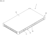
- FIG. 1 is a perspective view schematically illustrating a honeycomb sandwich type vacuum insulation panel according to the present disclosure.
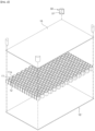
- FIG. 2 is an exploded perspective view schematically illustrating a honeycomb sandwich type vacuum insulation panel according to the present disclosure.
- FIG. 3 is a side view schematically illustrating a honeycomb sandwich type vacuum insulation panel according to the present disclosure.
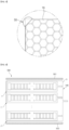
- FIG. 4 is a diagram schematically illustrating a honeycomb sandwich type vacuum insulation panel of the honeycomb sandwich type vacuum insulation panel according to the present disclosure and is an enlarged plan view of A portion of FIG. 3 .
- FIG. 5 is a diagram schematically illustrating a breakage prevention pad installed on a honeycomb sandwich panel of a honeycomb sandwich type vacuum insulation panel according to the present disclosure and is an enlarged plan view of B portion of FIG. 3 .
- FIG. 1 is a perspective view schematically illustrating a honeycomb sandwich type vacuum insulation panel according to the present disclosure.
- FIG. 2 is an exploded perspective view schematically illustrating a honeycomb sandwich type vacuum insulation panel according to the present disclosure
- FIG. 6 is a side view schematically illustrating a honeycomb sandwich type vacuum insulation panel system according to one embodiment of the present disclosure.
- FIG. 7 is a side view schematically illustrating a multilayer stacked honeycomb sandwich type vacuum insulation panel system according to one embodiment of the present disclosure.
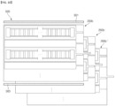
- FIG. 8 is a side view schematically illustrating a honeycomb sandwich type vacuum insulation panel system according to another embodiment of the present disclosure.
- FIG. 9 is a side view schematically illustrating an example of a multilayer stacked honeycomb sandwich type vacuum insulation panel system according to another embodiment of the present disclosure.
- FIG. 10 is a side view schematically illustrating another example of a multilayer stacked honeycomb sandwich type vacuum insulation panel system according to another embodiment of the present disclosure.
- a honeycomb sandwich type vacuum insulation panel 1 for insulating a cryogenic liquid fuel storage tank 500 in which a cryogenic liquid fuel including liquid hydrogen or the like is accommodated therein, comprises a honeycomb sandwich panel 10, a vacuum film 30, and a breakage prevention pad 50.
- the honeycomb sandwich panel 10 which is installed between a primary gas barrier 501 and a secondary gas barrier 503 provided in a flat hexahedral-shaped cryogenic liquid fuel storage tank 500 for insulating the cryogenic liquid fuel storage tank 500, includes a honeycomb structure 11 connected formed by a plurality of honeycombs 11a, and composite panels 16, 16' installed in the honeycomb structure 11.
- the honeycomb structure 11 comprises a plurality of honeycombs 11a formed with open upper and lower portions, filling spaces 12 formed in the inside of the honeycombs 11a, and an insulation material 17 filled in each of the filling spaces 12 to improve the insulation properties of the honeycomb sandwich panel 10.
- the insulation material 17 may comprise at least one of air, vacuum, aerogel, or insulation powder.
- the filling space 12 of each honeycomb 11a is filled with air, vacuum, aerogel, or insulation powder as an insulation material 17, but it is possible to make various modifications, not limited thereto, if the filling space 12 is filled to facilitate insulation of the honeycomb sandwich panel 10.
- the composite panels 16, 16' are installed on the top surface and the bottom surface of the honeycomb structure 11, respectively.
- the composite panels 16, 16' are formed as a flat panel (FP) or a corner panel (CP) and are bonded and installed on the open upper portion and the lower portion of the plurality of honeycombs 11a formed in the honeycomb structure 11, respectively, so that the upper and lower portions of the honeycombs 11a can be sealed and airtightly processed.
- FP flat panel
- CP corner panel
- the honeycomb structure 11 in which the plurality of honeycombs 11a are connected formed is preferably formed in the form of a square or rectangular shape in the overall outline, and composite panels 16, 16' of a size corresponding to the size of the honeycomb structure 11 are preferably installed on the top surface and the bottom surface of the honeycomb structure 11, but it is also possible to form and install the horizontal and vertical lengths of the honeycomb structure 11 corresponding to the area of the cryogenic liquid fuel storage tank 500.
- honeycomb structure 11 it is also possible to form the honeycomb structure 11 as a single piece, and to install the composite panels 16, 16' of a corresponding size on the top surface and the bottom surface of the honeycomb structure 11 in the form of a cuboid or a cube, and then to manufacture and apply each honeycomb structure 11 manufactured as a single piece by interconnecting and coupling them to correspond to the length required at the site, and it is also possible to vary the thickness of the honeycomb structure 11 in a variety of ways.
- the honeycomb structure 11 and the composite panels 16, 16' are formed in the form of a cuboid, but this is only an example, but not limited thereto, and various modifications can be performed.
- the composite panels 16, 16' are installed on the top surface and the bottom surface of the honeycomb structure 11, respectively, but the composite panels 16, 16' may also be installed on each side of the honeycomb structure 11, respectively, and other various modifications can be performed.
- the composite panels 16, 16' may be formed as a composite of a resin and a glass fiber or a carbon fiber or an aramid fiber or a synthetic fiber.
- the composite panels 16, 16' may be formed from a composite of resin and glass fiber or formed from a composite of resin and carbon fiber, or formed from a composite of resin and aramid fiber, or formed from a composite of resin and synthetic fiber.
- the vacuum film 30 accommodates the honeycomb sandwich panel 10 inside and vacuumizes.
- the vacuum film 30 may be formed in two layers so that an accommodated space for accommodating the honeycomb sandwich panel 10 inside is formed, wherein one layer of the vacuum film 30 is disposed to contact the lower portion or one side surface of the honeycomb sandwich panel 10, and the other layer of the vacuum film 30 is disposed on the upper portion or the other side surface of the honeycomb sandwich panel 10, and then the respective edges of the vacuum film 30 are thermally fused.
- the vacuum port 31 is protruded formed on one side of the vacuum film 30, and the vacuum film 30 can be vacuumed through the vacuum port 31.
- the position of the vacuum port 31 can be variously modified.
- the vacuum film 30 may be made of a Nylon material that is not easily damaged or broken by external impact but is not limited thereto.
- the breakage prevention pads 50 are installed at each corner of the honeycomb sandwich panel 10 in contact with the vacuum film 30 to prevent breakage of the vacuum film 30 by the sharp edges of the honeycomb sandwich panel 10.
- the breakage prevention pad 50 is a cover body in a semicircular shape, in which an insertion groove 51 corresponding to the shape of the corner is formed therein for insertion and coupling of each corner of the honeycomb sandwich panel 10.
- the breakage prevention pad 50 may be made of a Nylon material.
- honeycomb sandwich panel 10 according to the present disclosure can be used by using the honeycomb structure 11 alone, or by installing composite panels 16, 16' on the top surface and bottom surface of the honeycomb structure 11.
- the filling space 12 formed in the plurality of honeycombs 11a of the honeycomb structure 11 can be filled with insulation material 17, and the honeycomb structure 11 filled with the insulation material 17 can be vacuumed by installing a breakage prevention pad 50 in the vacuum film 30 after installing it.
- the length in the vertical direction of the insertion groove 51 of the breakage prevention pad 50 may be formed corresponding to the thickness of the honeycomb structure 11 without the composite panels 16, 16'.
- the filling space 12 formed in each honeycomb 11a of the honeycomb structure 11 formed in a certain length is filled with insulation material 17.
- the honeycomb sandwich panel 10 is manufactured by installing the composite panels 16, 16' on the top surface and the bottom surface of the honeycomb structure 11.
- a breakage prevention pad 50 is installed at each corner of the honeycomb sandwich panel 10 manufactured in this manner.
- the insertion grooves 51 of the breakage prevention pads 50 are inserted into the respective corners of the honeycomb sandwich panel 10.
- the vacuum film 30 is vacuumed through the vacuum port 31 of the vacuum film 30 to manufacture the honeycomb sandwich type vacuum insulation panel 1.
- honeycomb sandwich type vacuum insulation panel 1 manufactured as described above can be installed between the primary gas barrier 501 and the secondary gas barrier 503 of the cryogenic liquid fuel storage tank 500 to insulate the cryogenic liquid fuel storage tank 500.
- the honeycomb sandwich type vacuum insulation panel 1 according to the present disclosure can be accommodated in a leakage prevention barrier 5 and vacuumed to form a honeycomb sandwich type vacuum insulation panel system 100.
- the leakage prevention barrier 5 may be made of a Nylon material that is not easily torn or broken by external impact.
- the leakage prevention barrier 5 is made of a Nylon material, but it is preferred that the leakage prevention barrier 5 is made of an insulation material.
- the leakage prevention barrier 5 may be made of a combination of insulation materials comprising any one or more of LLDPE (Liner Low Density PolyEthylene), PET or PI manufactured by aluminum deposition, EVOH (Ethylene Vinyl alcohol), AlOx (aluminum oxide), not limited thereto, and various other modifications can be performed.
- LLDPE Liner Low Density PolyEthylene
- PET or PI manufactured by aluminum deposition
- EVOH Ethylene Vinyl alcohol
- AlOx aluminum oxide
- a vacuum port (not shown) is also formed in the leakage prevention barrier 5 for vacuuming the honeycomb sandwich type vacuum insulation panel 1 accommodated therein. Again, the position of the vacuum port can be variously modified.
- the honeycomb sandwich type vacuum insulation panels 1, 1', ...,1 n accommodated within the leakage prevention barrier 5 are provided in at least one plurality of pieces, but the honeycomb sandwich type vacuum insulation panels 1, 1', ... ,1 n accommodated within the leakage prevention barrier 5 may be disposed in a plurality of pieces with respect to the thickness direction of the vacuum insulation panel 1.
- the plurality of honeycomb sandwich type vacuum insulation panels 1, 1', .. ⁇ , 1 n may be disposed and accommodated in the thickness direction in the leakage prevention barrier 5 and then vacuumed to form a honeycomb sandwich type vacuum insulation panel system 100.
- the honeycomb sandwich type vacuum insulation panel system 100, 100', 100" can insulate the cryogenic liquid fuel storage tank 500 by forming a plurality of honeycomb sandwich type vacuum insulation panel systems 100, 100', 100" disposed in the horizontal direction of the vacuum insulation panel system 100 to form a multilayer.
- the honeycomb sandwich type vacuum insulation panel system 200 may be disposed in a plurality of honeycomb sandwich type vacuum insulation panels 1, 1' and polyurethane foam type vacuum insulation panels 3, 3' in the leakage prevention barrier 5 with respect to the thickness direction.
- the polyurethane foam type vacuum insulation panels 3, 3' commonly applied between the primary gas barrier 501 and the secondary gas barrier 503 provided in the cryogenic liquid fuel storage tank 500 and the honeycomb sandwich type vacuum insulation panel 1, 1' are disposed in the leakage prevention barrier 5 in the thickness direction, but the polyurethane foam type vacuum insulation panels 3, 3' and the honeycomb sandwich type vacuum insulation panels 1, 1' are alternately mixed and disposed to form the honeycomb sandwich type vacuum insulation panel system 200.
- the structural strength and stiffness may be higher than the required strength and stiffness when the vacuum insulation panel system 100 comprising only the honeycomb sandwich type vacuum insulation panels 1, 1' is installed in the cryogenic liquid fuel storage tank 500, it is necessary to use the polyurethane foam type vacuum insulation panels 3, 3' with different heat transfer coefficients and the honeycomb sandwich type vacuum insulation panels 1, 1', as shown in FIG. 8 , are mixed to manufacture the vacuum insulation panel system 200, which can be advantageous in terms of cost compared to the vacuum insulation panel system 100 comprising only the honeycomb sandwich type vacuum insulation panels 1, 1', and can meet the structural robustness and stiffness required in the field.
- the honeycomb sandwich type vacuum insulation panel system 200 formed by mixing the polyurethane foam type vacuum insulation panels 3, 3' and the honeycomb sandwich type vacuum insulation panels 1, 1', wherein the vacuum insulation panel system 200 is disposed horizontally between the primary gas barrier 501 and the secondary gas barrier 503 provided in the cryogenic liquid fuel storage tank 500 to form a multilayer, thereby the cryogenic liquid fuel storage tank 500 can be insulated.
- any one of the multilayer stacked vacuum insulation panel systems 200a comprises a polyurethane foam type vacuum insulation panel 3, 3' and a honeycomb sandwich type vacuum insulation panel system 1, 1' are alternately disposed with respect to the thickness direction, and the other vacuum insulation panel system 200a', which is disposed in the horizontal direction thereof, is disposed in the opposite alternation, wherein the polyurethane foam type vacuum insulation panels 3, 3' and the honeycomb sandwich type vacuum insulation panels 1, 1' are disposed, and another vacuum insulation panel system 200a" stacked in the horizontal direction thereof may be formed in the same form as any one of the vacuum insulation panel systems 200a so that the polyurethane foam type vacuum insulation panels 3, 3' and the honeycomb sandwich type vacuum insulation panels 1, 1' are alternately stacked in the same position with respect to the horizontal direction of each of the vacuum insulation panel systems 200a, 200a', 200a".
- the honeycomb sandwich type vacuum insulation panel 1, 1' is located in the upper portion or the lower portion of the thickness direction of the polyurethane foam type vacuum insulation panel 3, 3', and the honeycomb sandwich type vacuum insulation panel 1, 1' is located in the upper portion or the lower portion of the thickness direction of the polyurethane foam type vacuum insulation panel 3, 3' are positioned such that the polyurethane foam type vacuum insulation panels 3, 3' and the honeycomb sandwich type vacuum insulation panels 1, 1' are alternately stacked with respect to the thickness direction, and then each vacuum insulation panel 1, 1' is disposed in a horizontal direction to form a multilayer stacked honeycomb sandwich type vacuum insulation panel system 200a, 200a', 200a".
- the cryogenic liquid fuel storage tank 500 which stores liquefied natural gas in a cryogenic state, can be insulated and prevent damage or breakage due to thermal shock.
- any one multilayer stacked vacuum insulation panel system 200b comprises a polyurethane foam type vacuum insulation panel 3, 3' and a honeycomb sandwich type vacuum insulation panel 1, 1' are alternately disposed with respect to the thickness direction, and another vacuum insulation panel system 200b' and another vacuum insulation panel system 200b" disposed in the horizontal direction are likewise composed of a polyurethane foam type vacuum insulation panel 3, 3' and the honeycomb sandwich type vacuum insulation panels 1, 1' are alternately disposed with respect to the thickness direction, so that the polyurethane foam type vacuum insulation panels 3, 3' are located in the same position with respect to the horizontal direction of each of the vacuum insulation panel systems 200b, 200b', 200b", or the honeycomb sandwich type vacuum insulation panels 1, 1' are stacked so that the polyurethane foam type vacuum insulation panels 3, 3' are located in the same position.
- the polyurethane foam type vacuum insulation panels 3, 3' are continuously disposed in the horizontal direction between the primary gas barrier 501 and the secondary gas barrier 503 provided in the cryogenic liquid fuel storage tank 500, or the honeycomb sandwich type vacuum insulation panels 1, 1' are continuously disposed and positioned in the horizontal direction of the honeycomb sandwich type vacuum insulation panel 1, 1', etc., so that the same vacuum insulation panel can be repeatedly stacked with respect to the thickness direction and the horizontal direction to form the vacuum insulation panel system 200B.
- honeycomb sandwich panel 10 the honeycomb sandwich type vacuum insulation panel 1, and the vacuum insulation panel system 100 of the present disclosure are described as an example, they are installed between the primary gas barrier 501 and the secondary gas barrier 503 of a flat hexahedral-shaped membrane type cryogenic liquid fuel storage tank 500 to insulate the cryogenic liquid fuel storage tank 500, not limited to application to the cryogenic liquid fuel storage tank 500 of a liquefied cargo carrier, it will be apparent that the above structure may also be applied to a marine structure, an architectural structure, or a civil structure, etc., so as to minimize heat losses and satisfy structural robustness to various loads, and may be applied to various other fields.
- the present disclosure is an optimal invention that can improve and maximize insulation of a cryogenic liquid fuel storage tank and minimize heat loss by forming an insulation panel installed between a primary gas barrier and a secondary gas barrier of a cryogenic liquid fuel storage tank to a honeycomb sandwich panel of a honeycomb structure.
Landscapes
- Engineering & Computer Science (AREA)
- Mechanical Engineering (AREA)
- General Engineering & Computer Science (AREA)
- Chemical & Material Sciences (AREA)
- Combustion & Propulsion (AREA)
- Ocean & Marine Engineering (AREA)
- Physics & Mathematics (AREA)
- Thermal Sciences (AREA)
- Filling Or Discharging Of Gas Storage Vessels (AREA)
Applications Claiming Priority (2)
| Application Number | Priority Date | Filing Date | Title |
|---|---|---|---|
| KR1020220078871A KR102573590B1 (ko) | 2022-06-28 | 2022-06-28 | 허니컴 샌드위치 타입의 진공단열패널 및 진공단열패널 시스템 |
| PCT/KR2022/009989 WO2024005251A1 (ko) | 2022-06-28 | 2022-07-08 | 허니컴 샌드위치 타입의 진공단열패널 및 진공단열패널 시스템 |
Publications (2)
| Publication Number | Publication Date |
|---|---|
| EP4549306A1 true EP4549306A1 (de) | 2025-05-07 |
| EP4549306A4 EP4549306A4 (de) | 2025-10-22 |
Family
ID=87973404
Family Applications (1)
| Application Number | Title | Priority Date | Filing Date |
|---|---|---|---|
| EP22949544.5A Pending EP4549306A4 (de) | 2022-06-28 | 2022-07-08 | Wabenförmige sandwich-vakuumisolationsplatte und vakuumisolationsplattensystem |
Country Status (4)
| Country | Link |
|---|---|
| EP (1) | EP4549306A4 (de) |
| KR (1) | KR102573590B1 (de) |
| CN (1) | CN119343293A (de) |
| WO (1) | WO2024005251A1 (de) |
Cited By (1)
| Publication number | Priority date | Publication date | Assignee | Title |
|---|---|---|---|---|
| CN120171948A (zh) * | 2025-05-23 | 2025-06-20 | 中太能源科技(上海)有限公司 | 液货存储系统 |
Families Citing this family (2)
| Publication number | Priority date | Publication date | Assignee | Title |
|---|---|---|---|---|
| KR20250163636A (ko) | 2024-05-14 | 2025-11-21 | 노민혁 | 진공 샌드위치 패널 |
| CN119975664B (zh) * | 2025-02-11 | 2025-11-14 | 沪东中华造船(集团)有限公司 | 一种气凝胶改良的蜂窝状聚氨酯绝热模块 |
Family Cites Families (11)
| Publication number | Priority date | Publication date | Assignee | Title |
|---|---|---|---|---|
| US3365897A (en) * | 1966-06-17 | 1968-01-30 | Nasa Usa | Cryogenic thermal insulation |
| EP0400097A1 (de) * | 1988-04-30 | 1990-12-05 | Korfmacher Trading Gmbh | Lagerungs- oder stützmatte, insbesondere für verpackungszwecke |
| US5950835A (en) * | 1996-12-24 | 1999-09-14 | Tenneco Packaging Inc. | Honeycomb protector with impact resistant corner |
| US5804278A (en) * | 1997-01-03 | 1998-09-08 | Fixtures Manufacturing Corporation | Laminated panel construction with honeycomb grid core |
| JP2002340280A (ja) * | 2001-05-18 | 2002-11-27 | Jamco Corp | 真空断熱ブロック |
| US6858280B2 (en) * | 2002-02-26 | 2005-02-22 | Technology Applications, Inc. | Microsphere insulation systems |
| KR101496848B1 (ko) * | 2013-07-03 | 2015-03-03 | 김광식 | 진공 단열재 |
| KR20200136132A (ko) * | 2019-05-27 | 2020-12-07 | 한동현 | Lng 저장탱크 내의 2차방벽 접착시 2차방벽에 열을 가하는 히팅판넬 및 이를 포함하는 가압장치 |
| CN210733467U (zh) * | 2019-08-23 | 2020-06-12 | 巩义市泛锐熠辉复合材料有限公司 | 一种蜂巢气凝胶结构真空绝热板 |
| KR102180562B1 (ko) | 2019-08-27 | 2020-11-18 | 부산대학교 산학협력단 | 액화수소 화물창 단열시스템 및 그 제조 방법 |
| KR20220078871A (ko) | 2020-12-04 | 2022-06-13 | 최영진 | 이불 말아주는 기계 |
-
2022
- 2022-06-28 KR KR1020220078871A patent/KR102573590B1/ko active Active
- 2022-07-08 WO PCT/KR2022/009989 patent/WO2024005251A1/ko not_active Ceased
- 2022-07-08 CN CN202280096972.8A patent/CN119343293A/zh active Pending
- 2022-07-08 EP EP22949544.5A patent/EP4549306A4/de active Pending
Cited By (1)
| Publication number | Priority date | Publication date | Assignee | Title |
|---|---|---|---|---|
| CN120171948A (zh) * | 2025-05-23 | 2025-06-20 | 中太能源科技(上海)有限公司 | 液货存储系统 |
Also Published As
| Publication number | Publication date |
|---|---|
| WO2024005251A1 (ko) | 2024-01-04 |
| CN119343293A (zh) | 2025-01-21 |
| KR102573590B1 (ko) | 2023-09-05 |
| EP4549306A4 (de) | 2025-10-22 |
Similar Documents
| Publication | Publication Date | Title |
|---|---|---|
| EP4549306A1 (de) | Wabenförmige sandwich-vakuumisolationsplatte und vakuumisolationsplattensystem | |
| KR101772581B1 (ko) | 독립형 액화가스 저장탱크의 교차적층 된 진공단열패널의 연결 구조 | |
| KR102700036B1 (ko) | 액화가스 저장탱크 및 이를 포함하는 선박 | |
| KR102535971B1 (ko) | 멤브레인형 저장탱크의 단열시스템 및 이를 포함하는 멤브레인형 저장탱크 | |
| CN111683870B (zh) | 极低温液化气体运输船的货舱及液化气体燃料容器的膜状物型隔热系统 | |
| JP2021500511A (ja) | 複数の領域を持つ密閉断熱タンク | |
| CN119013500A (zh) | 用于密封且隔热的容器的壁 | |
| KR102608691B1 (ko) | 액화천연가스 저장탱크의 단열시스템 | |
| KR102168127B1 (ko) | 액화가스 화물창의 단열시스템 | |
| US12403988B2 (en) | Corner structure and liquefied gas storage tank having same | |
| US12270512B2 (en) | Corner structure and liquefied gas storage tank having same | |
| KR20100134878A (ko) | Lng선 멤브레인 단열박스 | |
| KR102525949B1 (ko) | 멤브레인형 저장탱크의 단열시스템 및 이를 포함하는 멤브레인형 저장탱크 | |
| EP3733500A1 (de) | Membranverklebungsvorrichtung und flüssiggasspeicherbehälter damit | |
| CN114556010A (zh) | 具有面板间绝缘插入件的密封且热绝缘的罐 | |
| KR102951959B1 (ko) | 액화가스 저장탱크의 단열구조 및 상기 액화가스 저장탱크의 단열구조 형성방법 | |
| KR20220163256A (ko) | 액화 가스 저장 탱크 및 이를 포함하는 선박 | |
| KR20150000855U (ko) | 초저온 화물창 단열시스템의 단열박스 구조물 | |
| KR200500107Y1 (ko) | 액화가스 저장탱크 제작용 장치 | |
| KR20250160057A (ko) | 액화가스 저장탱크 및 이를 포함하는 선박 | |
| CN118871709A (zh) | 用于密封绝热贮罐的绝热箱 | |
| KR20240076740A (ko) | 단열부재 및 이를 포함하는 액화가스 저장탱크 | |
| KR102426553B1 (ko) | 국부 손상을 방지하는 2차 방벽 단열구조를 포함하는 lng 저장탱크 | |
| KR20250092548A (ko) | 코너 구조체 및 이를 포함하는 액화가스 저장탱크 | |
| KR20240088618A (ko) | 단열부재, 액화가스 저장탱크 및 선박 |
Legal Events
| Date | Code | Title | Description |
|---|---|---|---|
| STAA | Information on the status of an ep patent application or granted ep patent |
Free format text: STATUS: THE INTERNATIONAL PUBLICATION HAS BEEN MADE |
|
| PUAI | Public reference made under article 153(3) epc to a published international application that has entered the european phase |
Free format text: ORIGINAL CODE: 0009012 |
|
| STAA | Information on the status of an ep patent application or granted ep patent |
Free format text: STATUS: REQUEST FOR EXAMINATION WAS MADE |
|
| 17P | Request for examination filed |
Effective date: 20241125 |
|
| AK | Designated contracting states |
Kind code of ref document: A1 Designated state(s): AL AT BE BG CH CY CZ DE DK EE ES FI FR GB GR HR HU IE IS IT LI LT LU LV MC MK MT NL NO PL PT RO RS SE SI SK SM TR |
|
| REG | Reference to a national code |
Ref country code: DE Ref legal event code: R079 Free format text: PREVIOUS MAIN CLASS: B63B0025160000 Ipc: B32B0003120000 |
|
| DAV | Request for validation of the european patent (deleted) | ||
| DAX | Request for extension of the european patent (deleted) | ||
| A4 | Supplementary search report drawn up and despatched |
Effective date: 20250922 |
|
| RIC1 | Information provided on ipc code assigned before grant |
Ipc: B63B 25/16 20060101ALI20250916BHEP Ipc: F16L 59/065 20060101ALI20250916BHEP Ipc: F17C 3/02 20060101ALI20250916BHEP Ipc: F17C 13/00 20060101ALI20250916BHEP Ipc: B32B 3/12 20060101AFI20250916BHEP Ipc: B32B 1/00 20240101ALI20250916BHEP Ipc: B32B 3/08 20060101ALI20250916BHEP |