EP4549081A1 - Column and machine tool - Google Patents
Column and machine tool Download PDFInfo
- Publication number
- EP4549081A1 EP4549081A1 EP23831205.2A EP23831205A EP4549081A1 EP 4549081 A1 EP4549081 A1 EP 4549081A1 EP 23831205 A EP23831205 A EP 23831205A EP 4549081 A1 EP4549081 A1 EP 4549081A1
- Authority
- EP
- European Patent Office
- Prior art keywords
- column
- mounting surface
- spindle
- machine tool
- disposed
- Prior art date
- Legal status (The legal status is an assumption and is not a legal conclusion. Google has not performed a legal analysis and makes no representation as to the accuracy of the status listed.)
- Pending
Links
Images




Classifications
-
- B—PERFORMING OPERATIONS; TRANSPORTING
- B23—MACHINE TOOLS; METAL-WORKING NOT OTHERWISE PROVIDED FOR
- B23Q—DETAILS, COMPONENTS, OR ACCESSORIES FOR MACHINE TOOLS, e.g. ARRANGEMENTS FOR COPYING OR CONTROLLING; MACHINE TOOLS IN GENERAL CHARACTERISED BY THE CONSTRUCTION OF PARTICULAR DETAILS OR COMPONENTS; COMBINATIONS OR ASSOCIATIONS OF METAL-WORKING MACHINES, NOT DIRECTED TO A PARTICULAR RESULT
- B23Q1/00—Members which are comprised in the general build-up of a form of machine, particularly relatively large fixed members
- B23Q1/01—Frames, beds, pillars or like members; Arrangement of ways
- B23Q1/017—Arrangements of ways
-
- B—PERFORMING OPERATIONS; TRANSPORTING
- B23—MACHINE TOOLS; METAL-WORKING NOT OTHERWISE PROVIDED FOR
- B23Q—DETAILS, COMPONENTS, OR ACCESSORIES FOR MACHINE TOOLS, e.g. ARRANGEMENTS FOR COPYING OR CONTROLLING; MACHINE TOOLS IN GENERAL CHARACTERISED BY THE CONSTRUCTION OF PARTICULAR DETAILS OR COMPONENTS; COMBINATIONS OR ASSOCIATIONS OF METAL-WORKING MACHINES, NOT DIRECTED TO A PARTICULAR RESULT
- B23Q1/00—Members which are comprised in the general build-up of a form of machine, particularly relatively large fixed members
- B23Q1/01—Frames, beds, pillars or like members; Arrangement of ways
-
- B—PERFORMING OPERATIONS; TRANSPORTING
- B23—MACHINE TOOLS; METAL-WORKING NOT OTHERWISE PROVIDED FOR
- B23Q—DETAILS, COMPONENTS, OR ACCESSORIES FOR MACHINE TOOLS, e.g. ARRANGEMENTS FOR COPYING OR CONTROLLING; MACHINE TOOLS IN GENERAL CHARACTERISED BY THE CONSTRUCTION OF PARTICULAR DETAILS OR COMPONENTS; COMBINATIONS OR ASSOCIATIONS OF METAL-WORKING MACHINES, NOT DIRECTED TO A PARTICULAR RESULT
- B23Q1/00—Members which are comprised in the general build-up of a form of machine, particularly relatively large fixed members
- B23Q1/01—Frames, beds, pillars or like members; Arrangement of ways
- B23Q1/015—Frames, beds, pillars
-
- B—PERFORMING OPERATIONS; TRANSPORTING
- B23—MACHINE TOOLS; METAL-WORKING NOT OTHERWISE PROVIDED FOR
- B23Q—DETAILS, COMPONENTS, OR ACCESSORIES FOR MACHINE TOOLS, e.g. ARRANGEMENTS FOR COPYING OR CONTROLLING; MACHINE TOOLS IN GENERAL CHARACTERISED BY THE CONSTRUCTION OF PARTICULAR DETAILS OR COMPONENTS; COMBINATIONS OR ASSOCIATIONS OF METAL-WORKING MACHINES, NOT DIRECTED TO A PARTICULAR RESULT
- B23Q1/00—Members which are comprised in the general build-up of a form of machine, particularly relatively large fixed members
- B23Q1/25—Movable or adjustable work or tool supports
- B23Q1/44—Movable or adjustable work or tool supports using particular mechanisms
- B23Q1/56—Movable or adjustable work or tool supports using particular mechanisms with sliding pairs only, the sliding pairs being the first two elements of the mechanism
- B23Q1/60—Movable or adjustable work or tool supports using particular mechanisms with sliding pairs only, the sliding pairs being the first two elements of the mechanism two sliding pairs only, the sliding pairs being the first two elements of the mechanism
- B23Q1/62—Movable or adjustable work or tool supports using particular mechanisms with sliding pairs only, the sliding pairs being the first two elements of the mechanism two sliding pairs only, the sliding pairs being the first two elements of the mechanism with perpendicular axes, e.g. cross-slides
- B23Q1/621—Movable or adjustable work or tool supports using particular mechanisms with sliding pairs only, the sliding pairs being the first two elements of the mechanism two sliding pairs only, the sliding pairs being the first two elements of the mechanism with perpendicular axes, e.g. cross-slides a single sliding pair followed perpendicularly by a single sliding pair
-
- B—PERFORMING OPERATIONS; TRANSPORTING
- B23—MACHINE TOOLS; METAL-WORKING NOT OTHERWISE PROVIDED FOR
- B23Q—DETAILS, COMPONENTS, OR ACCESSORIES FOR MACHINE TOOLS, e.g. ARRANGEMENTS FOR COPYING OR CONTROLLING; MACHINE TOOLS IN GENERAL CHARACTERISED BY THE CONSTRUCTION OF PARTICULAR DETAILS OR COMPONENTS; COMBINATIONS OR ASSOCIATIONS OF METAL-WORKING MACHINES, NOT DIRECTED TO A PARTICULAR RESULT
- B23Q1/00—Members which are comprised in the general build-up of a form of machine, particularly relatively large fixed members
- B23Q1/25—Movable or adjustable work or tool supports
- B23Q1/44—Movable or adjustable work or tool supports using particular mechanisms
- B23Q1/56—Movable or adjustable work or tool supports using particular mechanisms with sliding pairs only, the sliding pairs being the first two elements of the mechanism
- B23Q1/60—Movable or adjustable work or tool supports using particular mechanisms with sliding pairs only, the sliding pairs being the first two elements of the mechanism two sliding pairs only, the sliding pairs being the first two elements of the mechanism
- B23Q1/62—Movable or adjustable work or tool supports using particular mechanisms with sliding pairs only, the sliding pairs being the first two elements of the mechanism two sliding pairs only, the sliding pairs being the first two elements of the mechanism with perpendicular axes, e.g. cross-slides
- B23Q1/621—Movable or adjustable work or tool supports using particular mechanisms with sliding pairs only, the sliding pairs being the first two elements of the mechanism two sliding pairs only, the sliding pairs being the first two elements of the mechanism with perpendicular axes, e.g. cross-slides a single sliding pair followed perpendicularly by a single sliding pair
- B23Q1/626—Movable or adjustable work or tool supports using particular mechanisms with sliding pairs only, the sliding pairs being the first two elements of the mechanism two sliding pairs only, the sliding pairs being the first two elements of the mechanism with perpendicular axes, e.g. cross-slides a single sliding pair followed perpendicularly by a single sliding pair followed perpendicularly by a single sliding pair
-
- B—PERFORMING OPERATIONS; TRANSPORTING
- B23—MACHINE TOOLS; METAL-WORKING NOT OTHERWISE PROVIDED FOR
- B23Q—DETAILS, COMPONENTS, OR ACCESSORIES FOR MACHINE TOOLS, e.g. ARRANGEMENTS FOR COPYING OR CONTROLLING; MACHINE TOOLS IN GENERAL CHARACTERISED BY THE CONSTRUCTION OF PARTICULAR DETAILS OR COMPONENTS; COMBINATIONS OR ASSOCIATIONS OF METAL-WORKING MACHINES, NOT DIRECTED TO A PARTICULAR RESULT
- B23Q11/00—Accessories fitted to machine tools for keeping tools or parts of the machine in good working condition or for cooling work; Safety devices specially combined with or arranged in, or specially adapted for use in connection with, machine tools
- B23Q11/001—Arrangements compensating weight or flexion on parts of the machine
Definitions
- the present invention relates to a column and a machine tool.
- Patent Document 1 discloses a lateral machine tool that performs cutting and other machining on a workpiece fixed on a rotary table by using a spindle that extends horizontally.
- a carriage that is movable in the X-axis (left and right) direction is provided on the base of the machine tool.
- a column that is movable in the Z-axis (front-back) direction is provided on the carriage.
- a spindle head that is movable in the Y-axis (up and down) direction relative to the column is provided.
- a spindle is rotatably supported on the spindle head, and a tool is mounted on the spindle.
- Patent Document 1 Japanese Patent Application Laid-Open No. 8-108340
- a column movably supports the spindle head in the Y-axis direction.
- the column receives a reaction force from the workpiece via the tool, the spindle, and the spindle head.
- the column may twist horizontally relative to the base due to reaction forces. If the column twists horizontally, the tool will shift position relative to the workpiece. If the displacement due to torsion is large, the machine tool may not be able to machine the workpiece with high precision.
- An object of the present invention is to provide a column and a machine tool capable of reducing displacement due to torsion.
- a column according to claim 1 is disposed at an interval from a workbench that fixes a work material on an upper side of a foundation of a machine tool and supports a spindle head that holds a spindle.
- the column includes: a mounting surface disposed on a surface facing the workbench for mounting an up-down guide portion that guides a movement of the spindle head in an up-down direction; and an intersection guide portion disposed on a lower wall and guiding a movement of the column in an intersecting direction intersecting the up-down direction, in which in a plan view, at least a portion of the intersection guide portion is closer to the workbench than the mounting surface.
- the column compared with the case where at least a portion of the intersection guide portion is not positioned closer to the workbench than the mounting surface in a plan view, the position of the rotation center of the torsion relative to the foundation is closer to the workbench side. At this time, the distance from the rotation center of the torsion to the tip of the tool becomes shorter. Therefore, the column may reduce displacement due to torsion during machining.
- the intersection guide portion includes a first intersection guide portion, and a second intersection guide portion disposed further on an opposite side to the workbench than the first intersection guide portion, in which in a plan view, the first intersection guide portion may be closer to the workbench than the mounting surface.
- the column is disposed with the first intersection guide portion and the second intersection guide portion with the mounting surface therebetween. This allows the first intersection guide portion and the second intersection guide portion to guide the column more stably compared to the case where both are positioned closer to the workbench than the mounting surface. Therefore, the column can move stably in the intersecting direction.
- the lower wall has a protruding portion that protrudes toward the workbench further than the mounting surface, and the protruding portion is supported from below by the first intersection guide portion, and an upper end thereof may be inclined downward toward the workbench. Since the upper end of the protruding portion is inclined downward toward the workbench, the column can be supported without reducing rigidity. Therefore, the column can move stably in the intersecting direction.
- a machine tool according to claim 4 includes the column according to claim 3. Therefore, the machine tool can obtain the same effect as that of claim 3.
- the spindle may extend horizontally.
- the torsional displacement at the tip of the tool becomes large when torsion occurs.
- the distance from the rotation center of the torsion to the tip of the tool becomes shorter. Therefore, the machine tool can reduce displacement due to torsion during machining, even when the axial direction is horizontal.
- the left-right direction, the up-down direction, and the front-back direction of the machine tool 1 correspond to the X-axis direction, the Y-axis direction, and the Z-axis direction of the machine tool 1, respectively.
- the machine tool 1 shown in FIG. 1 is of a lateral type in which a spindle 7 (see FIG. 3 ) to be described below extends in the front-back direction (Z-axis direction), and a column 5 to be described below moves in the X-axis direction and the Z-axis direction.
- the machine tool 1 includes a base 2, the column 5, frame covers 10, 20, a spindle head 6, the spindle 7 (see FIG. 3 ), a control box 8, a rotary table 9, an X-axis moving mechanism 11, a Z-axis moving mechanism 12, a Y-axis moving mechanism 13, etc.
- the base 2 is an iron foundation having a substantially rectangular parallelepiped shape that is elongated in the Z-axis direction.
- the X-axis moving mechanism 11 is disposed at the rear portion of the upper surface of the base 2 and movably supports a moving body 15 in the X-axis direction.
- the Z-axis moving mechanism 12 is disposed on the upper surface of the moving body 15 and movably supports the column 5 in the Z-axis direction.
- the column 5 extends in the up-down direction.
- a frame cover 10 is mounted on the upper portion of the column 5.
- the frame cover 10 is a frame body having a rectangular shape in a plan view, and covers the column 5 from the outside.
- a frame cover 20 is mounted on the front surface of the column 5.
- the frame cover 20 is a frame body having a vertically elongated rectangular shape when viewed from the front, and covers the gap between the column 5 and the spindle head 6 to be described below from the outside.
- the upper surface of the frame cover 20 is provided with a hole that corresponds to the outer peripheral shape of a pedestal 21, which will be described later.
- the Y-axis moving mechanism 13 is disposed on the front surface of the column 5 and movably supports the spindle head 6 in the Y-axis direction.
- the X-axis moving mechanism 11 includes a pair of guides, a ball screw, and an X-axis motor.
- the Z-axis moving mechanism 12 includes a pair of guides 25 (see FIG. 5 ), a ball screw, and a Z-axis motor.
- the pair of guides 25 are rail-shaped and extend in the front-back direction, and are disposed at an interval from each other in the left-right direction.
- the Y-axis moving mechanism 13 includes a pair of guides 24 (see FIG. 6 ), a ball screw 27 (see FIG. 1 ), and a Y-axis motor.
- the pair of guides 24 are rail-shaped and extend in the up-down direction, and are mounted on the front side of the column 5 at an interval from each other in the left-right direction (see FIG. 6 ).
- the X-axis moving mechanism 11, the Z-axis moving mechanism 12, and the Y-axis moving mechanism 13 move the target parts (the moving body 15, the column 5, the spindle head 6) along each guide using
- the frame cover 20 has the pedestal 21 on its upper portion.
- the pedestal 21 has a substantially rectangular shape in a plan view.
- the pedestal 21 has a support hole 21A that passes through its upper surface in the up-down direction.
- a Y-axis motor of the Y-axis moving mechanism 13 (see FIG. 1 ) is inserted and fixed in the support hole 21A.
- the rotation shaft of the Y-axis motor protrudes downward inside the frame cover 20 and is connected to the upper end portion of the ball screw 27 (see FIG. 1 ).
- the spindle head 6 extends in the Z-axis direction, and is disposed movably in the Y-axis direction along the front surface of the column 5 by the Y-axis moving mechanism 13.
- the spindle head 6 includes an upper cover 28 and a lower cover 85.
- the upper cover 28 is a metal plate having a substantially rectangular shape when viewed from the front.
- the lower end portion of the upper cover 28 is fixed to the rear end portion of the upper surface of the spindle head 6.
- the upper cover 28 extends upward from the rear end portion of the upper surface of the spindle head 6.
- the upper cover 28 is disposed on the front side of the frame cover 20 and the pedestal 21 (see FIGS. 3 and 4 ).
- the upper cover 28 moves up and down integrally with the spindle head 6, thereby constantly covering from the front an area of the front surface of the column 5 that is further on an upper side than the spindle head 6.
- the lower cover 85 is fixed in a suspended state to the rear end portion of the lower surface of the spindle head 6.
- the lower cover 85 includes a plurality of metal plates arranged in the up-down direction, and expands and contracts in the up-down direction according to the height of the spindle head 6, thereby constantly covering from the front an area of the front surface of the column 5 that is further on the lower side than the spindle head 6 (see FIGS. 1 and 2 ).
- the spindle 7 is disposed within the spindle head 6 and extends in the Z-axis direction.
- the spindle head 6 rotatably supports the spindle 7.
- the rear portion of the spindle head 6 holds a spindle motor (not shown).
- An output shaft of the spindle motor extends forward and is coaxially connected to the rear end portion of the spindle 7.
- the spindle 7 rotates around the Z axis.
- a tool holder 90 (see FIG. 5 ) is detachably mounted on the spindle 7.
- the tool holder 90 holds a tool 91 at its front side.
- the base 2 includes a pair of support members 17, 18 (see FIG. 5 ) at the rear portion.
- the support members 17, 18 are spaced apart from each other in the left-right direction, extend upward, and support the control box 8 from below.
- the control box 8 houses a control panel (not shown) therein. The control panel controls the operation of the machine tool 1.
- the base 2 includes a fix stand 16 on the front side of the upper surface.
- the fix stand 16 is disposed on the front side of the X-axis moving mechanism 11.
- the rotary table 9 is rotatably supported by the fix stand 16.
- the rotary table 9 is located in front of the spindle head 6.
- the rotary table 9 has a workpiece 99 (see FIG. 9 ) fixed to its upper surface by a jig (not shown), and is rotatable 360° about a rotation axis parallel to the Y-axis direction.
- the column 5 is a rectangular cylinder having a vertically elongated rectangular shape when viewed from the front.
- the column 5 has a right wall 51A, a left wall 51B, an upper wall 51C, and a lower wall 51D.
- the column 5 has a through hole 5A surrounded by the right wall 51A, the left wall 51B, the upper wall 51C, and the lower wall 51D.
- the through hole 5A has a vertically elongated rectangular shape when viewed from the front.
- the right wall 51A has a mounting surface 52R and a mounting surface 54R.
- the mounting surface 52R is disposed at the left front end of the right wall 51A.
- the mounting surface 54R is disposed at the right front end of the right wall 51A and to the right side of the mounting surface 52R.
- the mounting surface 54R is located further rearward than the mounting surface 52R (see FIG. 8 ).
- the mounting surfaces 52R and 54R are each have a vertically elongated rectangle shape when viewed from the front.
- the mounting surface 52R has a plurality of screw holes 52A aligned in the up-down direction.
- One of the pair of guides 24 is mounted on the mounting surface 52R by screwing the screws into the screw holes 52A.
- the mounting surface 54R has a plurality of screw holes 54A aligned in the up-down direction.
- the frame cover 20 is mounted on the mounting surface 54R by screwing the screws into the screw holes 54A.
- a mounting surface 52L is disposed at the right front end of the left wall 51B.
- the mounting surface 52R and the mounting surface 52L are aligned at the same position in the front-back direction.
- a mounting surface 54L is located further rearward than the mounting surface 52L (see FIG. 8 ).
- the mounting surface 54L is disposed at the left front end of the left wall 51B and to the left side of the mounting surface 52L.
- the mounting surface 54L is located further rearward than the mounting surface 52L (see FIG. 8 ).
- the mounting surfaces 52L, 54L are each have a vertically elongated rectangle shape when viewed from the front.
- the mounting surface 52L is formed with a plurality of screw holes 52B aligned in the up-down direction.
- the other of the pair of guides 24 is mounted on the mounting surface 52L by screwing the screws into the screw holes 52B.
- the mounting surface 54L has a plurality of screw holes (not shown) aligned in the up-down direction.
- the frame cover 20 is mounted on the mounting surface 54L by screwing the screws into the screw holes.
- Mounting surfaces 53R and 53L are disposed on the upper wall 51C.
- the mounting surface 53R is disposed on the upper left side of the mounting surface 52R.
- the mounting surface 53L is disposed on the upper right side of the mounting surface 52L. As shown in FIG. 8 , the mounting surface 53R is located further rearward than the mounting surface 52R, and the mounting surface 53L is located further rearward than the mounting surface 52L.
- the mounting surface 53R and the mounting surface 53L are aligned at the same position in the front-back direction.
- the mounting surface 53R and the mounting surface 53L each have a vertically elongated rectangular shape when viewed from the front.
- the mounting surface 53R has a plurality of screw holes 53A.
- the mounting surface 53L has a plurality of screw holes 53B.
- the pedestal 21 is mounted on the mounting surface 53R by screwing the screws into the screw holes 53A.
- the pedestal 21 is mounted on the mounting surface 53L by screwing the screws into the screw holes 53B.
- the front end of the lower wall 51D has a protruding portion 55.
- the protruding portion 55 protrudes forward beyond the mounting surfaces 52R, 52L.
- An upper surface 55A of the protruding portion 55 is inclined downward toward the front.
- the frame cover 20 and the lower cover 85 are disposed on an upper side of the upper surface 55A (see FIGS. 1 to 4 ).
- a moving body 56 includes a plate member 56A, and sliding members 57R, 57L, 58R, and 58L.
- the plate member 56A is disposed at the lower end of the column 5.
- the sliding members 57R and 57L are disposed at the front end of the plate member 56A.
- the sliding member 57R is disposed at the right front end of the plate member 56A.
- a sliding member 57L is disposed at the left front end of the plate member 56A.
- the sliding members 57R, 57L are aligned at the same position in the front-back direction.
- a portion of each of the sliding members 57R, 57L is located further forward than the mounting surfaces 52R, 52L in a plan view (see FIG. 8 ).
- the sliding members 57R and 57L are rectangular boxes when viewed from the bottom.
- the sliding member 57R is able to slide in the front-back direction by being guided by the right guide 25 of the pair of guides 25 (see FIG. 5 ).
- the sliding member 57L is able to slide in the front-back direction by being guided by the left guide 25 of the pair of guides 25 (see FIG. 5 ).
- the sliding members 57 when there is no need to distinguish between the sliding members 57R and 57L, they will be collectively referred to as the sliding members 57. It is sufficient that the sliding members 57R, 57L are at least partially further forward than the mounting surfaces 52R, 52L in plan view, or may be all forward as shown in FIG. 8 .
- the sliding members 58R, 58L are disposed at the rear end portion of the plate member 56A.
- the sliding member 58R is disposed at the right rear end portion of the plate member 56A.
- the sliding member 58L is disposed at the left rear end portion of the plate member 56A.
- the sliding members 58R, 58L are aligned at the same position in the front-back direction.
- the sliding members 58R, 58L are located further rearward than the mounting surfaces 52R, 52L in a plan view (see FIG. 8 ).
- the sliding members 58R and 58L are rectangular boxes when viewed from the bottom.
- the sliding member 58R is able to slide in the front-back direction by being guided by the right guide 25 of the pair of guides 25 (see FIG.
- the sliding member 58L is able to slide in the front-back direction by being guided by the left guide 25 of the pair of guides 25 (see FIG. 5 ).
- the sliding members 58R and 58L when there is no need to distinguish between the sliding members 58R and 58L, they will be collectively referred to as the sliding members 58.
- the operation of the machine tool 1 during machining of the workpiece 99 will be described with reference to FIG. 1 to FIG. 5 , and FIG. 9 .
- the CPU of the control panel reads a Z-axis feed command in the NC program, it drives the motor of the Z-axis moving mechanism 12.
- the sliding members 57 and 58 are guided by the pair of guides 25 and slide forward.
- the spindle 7 advances along the Z axis to a position on the rotary table 9 close to the workpiece 99 and the tool 91.
- the CPU drives the spindle motor to rotate the spindle 7.
- the CPU drives the motors of the X-axis moving mechanism 11, the Z-axis moving mechanism 12, and the Y-axis moving mechanism 13 based on the commands of the NC program to move the spindle 7 relative to the workpiece 99, thereby machining the workpiece 99.
- the lower cover 85 expands and contracts in the up-down direction according to the height of the spindle head 6.
- the spindle 7 is positioned at the lower end of its movement range in the up-down direction (see FIGS. 2 and 4 )
- the plurality of metal plates of the lower cover 85 overlap in a downwardly inclined state as they move forward from the lower end of the spindle head 6.
- the protruding portion 55 located on the lower side of the lower cover 85 the upper surface 55A is inclined downward toward the front. Therefore, when the spindle 7 is moved in the up-down direction by the Y-axis moving mechanism 13, the protruding portion 55 does not interfere with the expansion and contraction of the lower cover 85 in the up-down direction.
- a column 60 shown in (b) of FIG. 9 is a column having a conventional structure as a comparative example.
- the column 60 includes a mounting surface 72R, a moving body 76, the spindle head 6, and the frame cover 20.
- the moving body 76 includes sliding members 77 (77R, 77L) and 78 (78R, 78L).
- the mounting surface 72R, the moving body 76, and the sliding members 77 (77R, 77L), 78 (78R, 78L) are configured to correspond to the mounting surface 52R, the moving body 56, and the sliding members 57 (57R, 57L), 58 (58R, 58L) of the column 5 of the present invention, respectively.
- the column 60 differs from the column 5 of the present invention in that it does not include the protruding portion 55 of the present invention, and the entire sliding member 77 is located further rearward than the mounting surface 72R.
- an intersection point between an imaginary line connecting the sliding members 57R and 58L and an imaginary line connecting the sliding members 57L and 58R is designated as Q1.
- an intersection point between an imaginary line connecting the sliding members 77R and 78L and an imaginary line connecting the sliding members 77L and 78R is designated as Q2.
- a distance L1 between the intersection point Q1 and the front end of the tool 91 is shorter than a distance L2 between the intersection point Q2 and the front end of the tool 91.
- the columns 5 and 60 may be twisted horizontally relative to the base 2 due to a reaction force from the workpiece 99.
- the tool 91 twists horizontally.
- the rotation centers of the torsion when the entire columns 5 and 60 twist horizontally become the intersection points Q1 and Q2 defined by the positional relationship of the sliding members 57, 58, 77, and 78.
- the displacement of the tool 91 due to torsion becomes smaller as the distances L1, L2 between the intersection points Q1, Q2 and the front end of the tool 91 become shorter. Since the distance L1 is shorter than the distance L2, the displacement of the tool 91 on the column 5 due to torsion is smaller than the displacement of the tool 91 on the column 60 due torsion.
- the spindle head 6 extends in the Z-axis direction and is disposed on the front surface the column 5 by the Y-axis moving mechanism 13.
- the rotary table 9 is located in front of the spindle head 6.
- the spindle head 6 is able to move in the Y-axis direction by being guided by the pair of guides 24 mounted on the mounting surfaces 52R, 52L of the column 5 (up-down direction).
- the mounting surface 52R is located at the left front end of the right wall 51A.
- the mounting surface 52L is located at the right front end of the left wall 51B.
- the column 5 is movable in the Z-axis direction (front-back direction) through the sliding members 57 and 58 being guided by the pair of guides 25.
- a portion of the sliding member 57 is located further forward than the mounting surface 52 in a plan view.
- the distance L1 between the intersection point Q1 on the column 5 and the front end of the tool 91 is shorter than the distance L2 between the intersection point Q2 on the column 60 of conventional structure and the front end of the tool 91.
- the displacement of the tool 91 due to torsion becomes smaller as the distances L1, L2 between the intersection points Q1, Q2, which are the rotation centers of the torsion, and the front end of the tool 91 become shorter. Since the distance L1 is shorter than the distance L2, the displacement of the tool 91 in the column 5 due to torsion is smaller than the displacement of the tool 91 in the column 60 of conventional structure due to torsion. Therefore, the column 5 can reduce displacement due to torsion when the workpiece 99 is machined.
- a portion of the sliding member 57 is located further forward than the mounting surfaces 52R and 52L in a plan view.
- the sliding member 58 is located further rearward than the mounting surfaces 52R, 52L in a plan view.
- the sliding member 57 and the sliding member 58 are disposed with the mounting surfaces 52R and 52L therebetween in the front-back direction in a plan view. This allows the sliding members 57, 58 to guide the column 5 more stably than when both are positioned further forward than the mounting surfaces 52R, 52L. Therefore, the column 5 is can move stably in the front-back direction.
- the protruding portion 55 is located further forward than the mounting surface 52.
- the upper surface 55A of the protruding portion 55 is inclined downward toward the front.
- the lower cover 85 is disposed on the upper side of the upper surface 55A.
- the plurality of metal plates of the lower cover 85 overlap in a state of being inclined downward as they move forward from the lower end of the spindle head 6. Since the upper surface 55A of the protruding portion 55 is inclined downward as it moves forward, when the spindle 7 is moved in the up-down direction by the Y-axis moving mechanism 13, the protruding portion 55 does not interfere with the expansion and contraction of the lower cover 85 in the up-down direction. Since the upper surface 55A of the protruding portion 55 is inclined downward as it moves forward, the column 5 may be supported without reducing rigidity. Therefore, the column 5 can move stably in the front-back direction.
- the spindle 7 extends in the Z-axis direction (front-back direction).
- the spindle 7 extends horizontally
- the tool 91 extending coaxially with the spindle 7 also twists horizontally. Therefore, the torsional displacement at the front end of the tool 91 is likely to become large.
- the rotation centers of the torsion when the entire columns 5 and 60 are twisted horizontally become the intersection points Q1 and Q2 defined by the positional relationship of the sliding members 57, 58, 77, and 78.
- the displacement of the tool 91 due to torsion becomes smaller as the distances L 1, L2 between the intersection points Q1, Q2 and the front end of the tool 91 become shorter.
- the machine tool 1 can reduce displacement due to torsion during machining of the workpiece 99 even when the spindle 7 extends horizontally.
- the base 2 is an example of a foundation of the present invention.
- the workpiece 99 is an example of a work material.
- the rotary table 9 is an example of a workbench of the present invention.
- the guide 24 is an example of an up-down guide portion of the present invention.
- the Z-axis direction (front-back direction) is an example of an intersecting direction in the present invention.
- the sliding members 57 and 58 are an example of an intersection guide portion of the present invention.
- the sliding member 57 is an example of a first intersection guide portion of the present invention.
- the sliding member 58 is an example of a second intersection guide portion of the present invention.
- the present invention is not limited to the above-described embodiment, and various modifications are possible.
- the various modified examples described below may be combined with each other as long as no contradiction occurs.
- the machine tool 1 in the above embodiment is a lateral machine tool in which the spindle 7 extends horizontally
- the present invention may also be applied to a vertical machine tool in which the spindle extends in the up-down direction.
- the positional relationship between the sliding members 57, 58 and the mounting surfaces 52R, 52L may be changed as follows. It is sufficient that the sliding members 57R, 57L are at least partially disposed further forward than the mounting surfaces 52R, 52L, and the sliding members 57R, 57L may be partially located further rearward than the mounting surfaces 52R, 52L.
- the sliding members 57, 58 may both be disposed further forward than the mounting surfaces 52R, 52L. In this case, it is sufficient that the sliding members 57 and 58 are located further rearward than the rotary table 9.
- the sliding member 58 may be disposed in the center portion of the plate member 56A in the front-back direction. In this case, the intersection point Q1 is closer to the front end of the tool 91, and the distance L1 is shorter. Therefore, the column 5 can further reduce the displacement of the tool 91 due to torsion.
- the upper surface 55A of the protruding portion 55 does not have to be inclined downward and forward.
- the upper surface 55A may be a horizontal surface.
- sliding members 57 and 58 may be configured to move along the pair of guides 25.
- rollers that roll on the pair of guides 25 may be used.
- the rotary table 9 may move in at least one of the X-axis direction, the Y-axis direction, and the Z-axis direction.
- the rotary table 9 may rotate about the X-axis.
Landscapes
- Engineering & Computer Science (AREA)
- Mechanical Engineering (AREA)
- Machine Tool Units (AREA)
Abstract
Description
- The present invention relates to a column and a machine tool.
-
Patent Document 1 discloses a lateral machine tool that performs cutting and other machining on a workpiece fixed on a rotary table by using a spindle that extends horizontally. A carriage that is movable in the X-axis (left and right) direction is provided on the base of the machine tool. A column that is movable in the Z-axis (front-back) direction is provided on the carriage. A spindle head that is movable in the Y-axis (up and down) direction relative to the column is provided. A spindle is rotatably supported on the spindle head, and a tool is mounted on the spindle. - Patent Document 1:
Japanese Patent Application Laid-Open No. 8-108340 - A column movably supports the spindle head in the Y-axis direction. When a workpiece is machined, the column receives a reaction force from the workpiece via the tool, the spindle, and the spindle head. The column may twist horizontally relative to the base due to reaction forces. If the column twists horizontally, the tool will shift position relative to the workpiece. If the displacement due to torsion is large, the machine tool may not be able to machine the workpiece with high precision.
- An object of the present invention is to provide a column and a machine tool capable of reducing displacement due to torsion.
- A column according to
claim 1 is disposed at an interval from a workbench that fixes a work material on an upper side of a foundation of a machine tool and supports a spindle head that holds a spindle. The column includes: a mounting surface disposed on a surface facing the workbench for mounting an up-down guide portion that guides a movement of the spindle head in an up-down direction; and an intersection guide portion disposed on a lower wall and guiding a movement of the column in an intersecting direction intersecting the up-down direction, in which in a plan view, at least a portion of the intersection guide portion is closer to the workbench than the mounting surface. In the column, compared with the case where at least a portion of the intersection guide portion is not positioned closer to the workbench than the mounting surface in a plan view, the position of the rotation center of the torsion relative to the foundation is closer to the workbench side. At this time, the distance from the rotation center of the torsion to the tip of the tool becomes shorter. Therefore, the column may reduce displacement due to torsion during machining. - In the column according to
claim 2, the intersection guide portion includes a first intersection guide portion, and a second intersection guide portion disposed further on an opposite side to the workbench than the first intersection guide portion, in which in a plan view, the first intersection guide portion may be closer to the workbench than the mounting surface. The column is disposed with the first intersection guide portion and the second intersection guide portion with the mounting surface therebetween. This allows the first intersection guide portion and the second intersection guide portion to guide the column more stably compared to the case where both are positioned closer to the workbench than the mounting surface. Therefore, the column can move stably in the intersecting direction. - In the column according to claim 3, the lower wall has a protruding portion that protrudes toward the workbench further than the mounting surface, and the protruding portion is supported from below by the first intersection guide portion, and an upper end thereof may be inclined downward toward the workbench. Since the upper end of the protruding portion is inclined downward toward the workbench, the column can be supported without reducing rigidity. Therefore, the column can move stably in the intersecting direction.
- A machine tool according to claim 4 includes the column according to claim 3. Therefore, the machine tool can obtain the same effect as that of claim 3.
- In the machine tool according to
claim 5, the spindle may extend horizontally. In the case where the spindle extends horizontally, the torsional displacement at the tip of the tool becomes large when torsion occurs. In the machine tool, the distance from the rotation center of the torsion to the tip of the tool becomes shorter. Therefore, the machine tool can reduce displacement due to torsion during machining, even when the axial direction is horizontal. -
- [
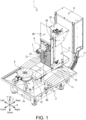
FIG. 1 ] a perspective view of a machine tool 1 (spindle head 6: raised). - [
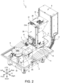
FIG. 2 ] a perspective view of the machine tool 1 (spindle head 6: lowered). - [
FIG. 3 ] a right side view of the machine tool 1 (spindle head 6: raised). - [
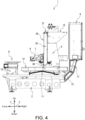
FIG. 4 ] a right side view of the machine tool 1 (spindle head 6: lowered). - [
FIG. 5 ] a plan view of themachine tool 1. - [
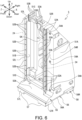
FIG. 6 ] a perspective view of acolumn 5. - [
FIG. 7 ] a right side view of thecolumn 5. - [
FIG. 8 ] a plan view of thecolumn 5 - [
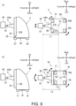
FIG. 9 ] an explanatory diagram of torsion ofcolumns workpiece 99. - An embodiment of the present invention will now be described. In the following description, arrows in the drawings will be used to indicate left and right, front and back, and up and down. The left-right direction, the up-down direction, and the front-back direction of the
machine tool 1 correspond to the X-axis direction, the Y-axis direction, and the Z-axis direction of themachine tool 1, respectively. Themachine tool 1 shown inFIG. 1 is of a lateral type in which a spindle 7 (seeFIG. 3 ) to be described below extends in the front-back direction (Z-axis direction), and acolumn 5 to be described below moves in the X-axis direction and the Z-axis direction. - The structure of the
machine tool 1 will be described with reference toFIG. 1 to FIG. 5 . As shown inFIG. 1 andFIG. 2 , themachine tool 1 includes abase 2, thecolumn 5, frame covers 10, 20, aspindle head 6, the spindle 7 (seeFIG. 3 ), acontrol box 8, a rotary table 9, anX-axis moving mechanism 11, a Z-axis moving mechanism 12, a Y-axis moving mechanism 13, etc. Thebase 2 is an iron foundation having a substantially rectangular parallelepiped shape that is elongated in the Z-axis direction. TheX-axis moving mechanism 11 is disposed at the rear portion of the upper surface of thebase 2 and movably supports a movingbody 15 in the X-axis direction. The Z-axis moving mechanism 12 is disposed on the upper surface of themoving body 15 and movably supports thecolumn 5 in the Z-axis direction. - The
column 5 extends in the up-down direction. The detailed structure of thecolumn 5 will be described later. Aframe cover 10 is mounted on the upper portion of thecolumn 5. Theframe cover 10 is a frame body having a rectangular shape in a plan view, and covers thecolumn 5 from the outside. Aframe cover 20 is mounted on the front surface of thecolumn 5. Theframe cover 20 is a frame body having a vertically elongated rectangular shape when viewed from the front, and covers the gap between thecolumn 5 and thespindle head 6 to be described below from the outside. The upper surface of theframe cover 20 is provided with a hole that corresponds to the outer peripheral shape of apedestal 21, which will be described later. The Y-axis moving mechanism 13 is disposed on the front surface of thecolumn 5 and movably supports thespindle head 6 in the Y-axis direction. - The
X-axis moving mechanism 11 includes a pair of guides, a ball screw, and an X-axis motor. The Z-axis moving mechanism 12 includes a pair of guides 25 (seeFIG. 5 ), a ball screw, and a Z-axis motor. The pair ofguides 25 are rail-shaped and extend in the front-back direction, and are disposed at an interval from each other in the left-right direction. The Y-axis moving mechanism 13 includes a pair of guides 24 (seeFIG. 6 ), a ball screw 27 (seeFIG. 1 ), and a Y-axis motor. The pair ofguides 24 are rail-shaped and extend in the up-down direction, and are mounted on the front side of thecolumn 5 at an interval from each other in the left-right direction (seeFIG. 6 ). TheX-axis moving mechanism 11, the Z-axis moving mechanism 12, and the Y-axis moving mechanism 13 move the target parts (the movingbody 15, thecolumn 5, the spindle head 6) along each guide using the power of each motor. - The
frame cover 20 has thepedestal 21 on its upper portion. Thepedestal 21 has a substantially rectangular shape in a plan view. Thepedestal 21 has asupport hole 21A that passes through its upper surface in the up-down direction. A Y-axis motor of the Y-axis moving mechanism 13 (seeFIG. 1 ) is inserted and fixed in thesupport hole 21A. The rotation shaft of the Y-axis motor protrudes downward inside theframe cover 20 and is connected to the upper end portion of the ball screw 27 (seeFIG. 1 ). - As shown in
FIGS. 1 to 4 , thespindle head 6 extends in the Z-axis direction, and is disposed movably in the Y-axis direction along the front surface of thecolumn 5 by the Y-axis moving mechanism 13. Thespindle head 6 includes anupper cover 28 and alower cover 85. Theupper cover 28 is a metal plate having a substantially rectangular shape when viewed from the front. The lower end portion of theupper cover 28 is fixed to the rear end portion of the upper surface of thespindle head 6. - The
upper cover 28 extends upward from the rear end portion of the upper surface of thespindle head 6. Theupper cover 28 is disposed on the front side of theframe cover 20 and the pedestal 21 (seeFIGS. 3 and4 ). Theupper cover 28 moves up and down integrally with thespindle head 6, thereby constantly covering from the front an area of the front surface of thecolumn 5 that is further on an upper side than thespindle head 6. Thelower cover 85 is fixed in a suspended state to the rear end portion of the lower surface of thespindle head 6. Thelower cover 85 includes a plurality of metal plates arranged in the up-down direction, and expands and contracts in the up-down direction according to the height of thespindle head 6, thereby constantly covering from the front an area of the front surface of thecolumn 5 that is further on the lower side than the spindle head 6 (seeFIGS. 1 and2 ). - As shown in
FIGS. 3 and4 , thespindle 7 is disposed within thespindle head 6 and extends in the Z-axis direction. Thespindle head 6 rotatably supports thespindle 7. The rear portion of thespindle head 6 holds a spindle motor (not shown). An output shaft of the spindle motor extends forward and is coaxially connected to the rear end portion of thespindle 7. When driven by the spindle motor, thespindle 7 rotates around the Z axis. A tool holder 90 (seeFIG. 5 ) is detachably mounted on thespindle 7. Thetool holder 90 holds atool 91 at its front side. - The
base 2 includes a pair ofsupport members 17, 18 (seeFIG. 5 ) at the rear portion. Thesupport members control box 8 from below. Thecontrol box 8 houses a control panel (not shown) therein. The control panel controls the operation of themachine tool 1. - The
base 2 includes afix stand 16 on the front side of the upper surface. The fix stand 16 is disposed on the front side of theX-axis moving mechanism 11. The rotary table 9 is rotatably supported by thefix stand 16. The rotary table 9 is located in front of thespindle head 6. The rotary table 9 has a workpiece 99 (seeFIG. 9 ) fixed to its upper surface by a jig (not shown), and is rotatable 360° about a rotation axis parallel to the Y-axis direction. - The structure of the
column 5 will be described with reference toFIG. 6 to FIG. 8 . Thecolumn 5 is a rectangular cylinder having a vertically elongated rectangular shape when viewed from the front. Thecolumn 5 has aright wall 51A, aleft wall 51B, anupper wall 51C, and alower wall 51D. Thecolumn 5 has a throughhole 5A surrounded by theright wall 51A, theleft wall 51B, theupper wall 51C, and thelower wall 51D. The throughhole 5A has a vertically elongated rectangular shape when viewed from the front. - The
right wall 51A has a mountingsurface 52R and a mountingsurface 54R. The mountingsurface 52R is disposed at the left front end of theright wall 51A. The mountingsurface 54R is disposed at the right front end of theright wall 51A and to the right side of the mountingsurface 52R. The mountingsurface 54R is located further rearward than the mountingsurface 52R (seeFIG. 8 ). The mountingsurfaces - The mounting
surface 52R has a plurality ofscrew holes 52A aligned in the up-down direction. One of the pair ofguides 24 is mounted on the mountingsurface 52R by screwing the screws into the screw holes 52A. The mountingsurface 54R has a plurality ofscrew holes 54A aligned in the up-down direction. Theframe cover 20 is mounted on the mountingsurface 54R by screwing the screws into the screw holes 54A. - A mounting
surface 52L is disposed at the right front end of theleft wall 51B. The mountingsurface 52R and the mountingsurface 52L are aligned at the same position in the front-back direction. A mountingsurface 54L is located further rearward than the mountingsurface 52L (seeFIG. 8 ). The mountingsurface 54L is disposed at the left front end of theleft wall 51B and to the left side of the mountingsurface 52L. The mountingsurface 54L is located further rearward than the mountingsurface 52L (seeFIG. 8 ). The mounting surfaces= 54R and the mountingsurface 54L are aligned at the same position in the front-back direction. The mounting surfaces 52L, 54L are each have a vertically elongated rectangle shape when viewed from the front. - The mounting
surface 52L is formed with a plurality ofscrew holes 52B aligned in the up-down direction. The other of the pair ofguides 24 is mounted on the mountingsurface 52L by screwing the screws into the screw holes 52B. The mountingsurface 54L has a plurality of screw holes (not shown) aligned in the up-down direction. Theframe cover 20 is mounted on the mountingsurface 54L by screwing the screws into the screw holes. - Mounting
surfaces upper wall 51C. The mountingsurface 53R is disposed on the upper left side of the mountingsurface 52R. The mountingsurface 53L is disposed on the upper right side of the mountingsurface 52L. As shown inFIG. 8 , the mountingsurface 53R is located further rearward than the mountingsurface 52R, and the mountingsurface 53L is located further rearward than the mountingsurface 52L. The mountingsurface 53R and the mountingsurface 53L are aligned at the same position in the front-back direction. The mountingsurface 53R and the mountingsurface 53L each have a vertically elongated rectangular shape when viewed from the front. The mountingsurface 53R has a plurality ofscrew holes 53A. The mountingsurface 53L has a plurality of screw holes 53B. Thepedestal 21 is mounted on the mountingsurface 53R by screwing the screws into the screw holes 53A. Thepedestal 21 is mounted on the mountingsurface 53L by screwing the screws into the screw holes 53B. - The front end of the
lower wall 51D has a protrudingportion 55. The protrudingportion 55 protrudes forward beyond the mountingsurfaces upper surface 55A of the protrudingportion 55 is inclined downward toward the front. Theframe cover 20 and thelower cover 85 are disposed on an upper side of theupper surface 55A (seeFIGS. 1 to 4 ). - A moving
body 56 includes aplate member 56A, and slidingmembers plate member 56A is disposed at the lower end of thecolumn 5. - The sliding
members plate member 56A. The slidingmember 57R is disposed at the right front end of theplate member 56A. A slidingmember 57L is disposed at the left front end of theplate member 56A. The slidingmembers members surfaces FIG. 8 ). The slidingmembers member 57R is able to slide in the front-back direction by being guided by theright guide 25 of the pair of guides 25 (seeFIG. 5 ). The slidingmember 57L is able to slide in the front-back direction by being guided by theleft guide 25 of the pair of guides 25 (seeFIG. 5 ). Hereinafter, when there is no need to distinguish between the slidingmembers members 57. It is sufficient that the slidingmembers surfaces FIG. 8 . - The sliding
members FIG. 8 ) are disposed at the rear end portion of theplate member 56A. The slidingmember 58R is disposed at the right rear end portion of theplate member 56A. The slidingmember 58L is disposed at the left rear end portion of theplate member 56A. The slidingmembers members surfaces FIG. 8 ). The slidingmembers member 58R is able to slide in the front-back direction by being guided by theright guide 25 of the pair of guides 25 (seeFIG. 5 ). The slidingmember 58L is able to slide in the front-back direction by being guided by theleft guide 25 of the pair of guides 25 (seeFIG. 5 ). Hereinafter, when there is no need to distinguish between the slidingmembers members 58. - The operation of the
machine tool 1 during machining of theworkpiece 99 will be described with reference toFIG. 1 to FIG. 5 , andFIG. 9 . When the CPU of the control panel reads a Z-axis feed command in the NC program, it drives the motor of the Z-axis moving mechanism 12. The slidingmembers guides 25 and slide forward. Thespindle 7 advances along the Z axis to a position on the rotary table 9 close to theworkpiece 99 and thetool 91. - The CPU drives the spindle motor to rotate the
spindle 7. In this state, the CPU drives the motors of theX-axis moving mechanism 11, the Z-axis moving mechanism 12, and the Y-axis moving mechanism 13 based on the commands of the NC program to move thespindle 7 relative to theworkpiece 99, thereby machining theworkpiece 99. - When the
spindle 7 moves in the up-down direction by the Y-axis moving mechanism 13, thelower cover 85 expands and contracts in the up-down direction according to the height of thespindle head 6. When thespindle 7 is positioned at the lower end of its movement range in the up-down direction (seeFIGS. 2 and4 ), the plurality of metal plates of thelower cover 85 overlap in a downwardly inclined state as they move forward from the lower end of thespindle head 6. In the protrudingportion 55 located on the lower side of thelower cover 85, theupper surface 55A is inclined downward toward the front. Therefore, when thespindle 7 is moved in the up-down direction by the Y-axis moving mechanism 13, the protrudingportion 55 does not interfere with the expansion and contraction of thelower cover 85 in the up-down direction. - As shown in (a) of
FIG. 9 , the slidingmember 57 is disposed below the protrudingportion 55, with a portion thereof disposed further forward than a mounting surface 52. Acolumn 60 shown in (b) ofFIG. 9 is a column having a conventional structure as a comparative example. Thecolumn 60 includes a mountingsurface 72R, a movingbody 76, thespindle head 6, and theframe cover 20. The movingbody 76 includes sliding members 77 (77R, 77L) and 78 (78R, 78L). The mountingsurface 72R, the movingbody 76, and the sliding members 77 (77R, 77L), 78 (78R, 78L) are configured to correspond to the mountingsurface 52R, the movingbody 56, and the sliding members 57 (57R, 57L), 58 (58R, 58L) of thecolumn 5 of the present invention, respectively. Thecolumn 60 differs from thecolumn 5 of the present invention in that it does not include the protrudingportion 55 of the present invention, and the entire slidingmember 77 is located further rearward than the mountingsurface 72R. - As shown in (a) of
FIG. 9 , in thecolumn 5, an intersection point between an imaginary line connecting the slidingmembers members FIG. 9 , in thecolumn 60, an intersection point between an imaginary line connecting the slidingmembers members tool 91 is shorter than a distance L2 between the intersection point Q2 and the front end of thetool 91. - Here, when the
machine tool 1 machines theworkpiece 99, thecolumns base 2 due to a reaction force from theworkpiece 99. As thecolumns tool 91 twists horizontally. The rotation centers of the torsion when theentire columns members tool 91 due to torsion becomes smaller as the distances L1, L2 between the intersection points Q1, Q2 and the front end of thetool 91 become shorter. Since the distance L1 is shorter than the distance L2, the displacement of thetool 91 on thecolumn 5 due to torsion is smaller than the displacement of thetool 91 on thecolumn 60 due to torsion. - As described above, in the
machine tool 1, thespindle head 6 extends in the Z-axis direction and is disposed on the front surface thecolumn 5 by the Y-axis moving mechanism 13. The rotary table 9 is located in front of thespindle head 6. Thespindle head 6 is able to move in the Y-axis direction by being guided by the pair ofguides 24 mounted on the mountingsurfaces surface 52R is located at the left front end of theright wall 51A. The mountingsurface 52L is located at the right front end of theleft wall 51B. Thecolumn 5 is movable in the Z-axis direction (front-back direction) through the slidingmembers guides 25. A portion of the slidingmember 57 is located further forward than the mounting surface 52 in a plan view. The distance L1 between the intersection point Q1 on thecolumn 5 and the front end of thetool 91 is shorter than the distance L2 between the intersection point Q2 on thecolumn 60 of conventional structure and the front end of thetool 91. The displacement of thetool 91 due to torsion becomes smaller as the distances L1, L2 between the intersection points Q1, Q2, which are the rotation centers of the torsion, and the front end of thetool 91 become shorter. Since the distance L1 is shorter than the distance L2, the displacement of thetool 91 in thecolumn 5 due to torsion is smaller than the displacement of thetool 91 in thecolumn 60 of conventional structure due to torsion. Therefore, thecolumn 5 can reduce displacement due to torsion when theworkpiece 99 is machined. - A portion of the sliding
member 57 is located further forward than the mountingsurfaces member 58 is located further rearward than the mountingsurfaces member 57 and the slidingmember 58 are disposed with the mountingsurfaces members column 5 more stably than when both are positioned further forward than the mountingsurfaces column 5 is can move stably in the front-back direction. - The protruding
portion 55 is located further forward than the mounting surface 52. Theupper surface 55A of the protrudingportion 55 is inclined downward toward the front. Thelower cover 85 is disposed on the upper side of theupper surface 55A. When thespindle 7 is located at the lower end of its movement range in the up-down direction, the plurality of metal plates of thelower cover 85 overlap in a state of being inclined downward as they move forward from the lower end of thespindle head 6. Since theupper surface 55A of the protrudingportion 55 is inclined downward as it moves forward, when thespindle 7 is moved in the up-down direction by the Y-axis moving mechanism 13, the protrudingportion 55 does not interfere with the expansion and contraction of thelower cover 85 in the up-down direction. Since theupper surface 55A of the protrudingportion 55 is inclined downward as it moves forward, thecolumn 5 may be supported without reducing rigidity. Therefore, thecolumn 5 can move stably in the front-back direction. - The
spindle 7 extends in the Z-axis direction (front-back direction). In the case where thespindle 7 extends horizontally, when thecolumn 5 twists horizontally, thetool 91 extending coaxially with thespindle 7 also twists horizontally. Therefore, the torsional displacement at the front end of thetool 91 is likely to become large. The rotation centers of the torsion when theentire columns members tool 91 due to torsion becomes smaller as thedistances L 1, L2 between the intersection points Q1, Q2 and the front end of thetool 91 become shorter. Since the distance L1 is shorter than the distance L2, the displacement of thetool 91 in thecolumn 5 due to torsion is smaller than the displacement of thetool 91 in thecolumn 60 of conventional structure due to torsion. Therefore, themachine tool 1 can reduce displacement due to torsion during machining of theworkpiece 99 even when thespindle 7 extends horizontally. - In the above embodiment, the
base 2 is an example of a foundation of the present invention. Theworkpiece 99 is an example of a work material. The rotary table 9 is an example of a workbench of the present invention. Theguide 24 is an example of an up-down guide portion of the present invention. The Z-axis direction (front-back direction) is an example of an intersecting direction in the present invention. The slidingmembers member 57 is an example of a first intersection guide portion of the present invention. The slidingmember 58 is an example of a second intersection guide portion of the present invention. - The present invention is not limited to the above-described embodiment, and various modifications are possible. The various modified examples described below may be combined with each other as long as no contradiction occurs. For example, although the
machine tool 1 in the above embodiment is a lateral machine tool in which thespindle 7 extends horizontally, the present invention may also be applied to a vertical machine tool in which the spindle extends in the up-down direction. - In the
column 5, the positional relationship between the slidingmembers surfaces members surfaces members surfaces members surfaces members member 58 may be disposed in the center portion of theplate member 56A in the front-back direction. In this case, the intersection point Q1 is closer to the front end of thetool 91, and the distance L1 is shorter. Therefore, thecolumn 5 can further reduce the displacement of thetool 91 due to torsion. - The
upper surface 55A of the protrudingportion 55 does not have to be inclined downward and forward. For example, theupper surface 55A may be a horizontal surface. - It is sufficient that the sliding
members guides 25. For example, instead of the slidingmembers guides 25 may be used. - The rotary table 9 may move in at least one of the X-axis direction, the Y-axis direction, and the Z-axis direction. The rotary table 9 may rotate about the X-axis.
-
- 1. Machine tool
- 5. Column
- 7. Spindle
- 52R, 52L Mounting surface
- 55 Protruding portion
- 56 Moving body
- 57, 58 Sliding member (intersection guide portion)
Claims (5)
- A column, disposed at an interval from a workbench that fixes a work material on an upper side of a foundation of a machine tool and supporting a spindle head that holds a spindle, the column comprising:a mounting surface, disposed on a surface facing the workbench for mounting an up-down guide portion that guides a movement of the spindle head in an up-down direction; andan intersection guide portion, disposed on a lower wall and guiding a movement of the column in an intersecting direction intersecting the up-down direction,wherein in a plan view, at least a portion of the intersection guide portion is closer to the workbench than the mounting surface.
- The column according to claim 1,wherein the intersection guide portion includes a first intersection guide portion, and a second intersection guide portion disposed further on an opposite side to the workbench than the first intersection guide portion, andwherein in plan view,the first intersection guide portion is closer to the workbench than the mounting surface.
- The column according to claim 2,wherein the lower wall has a protruding portion that protrudes toward the workbench than the mounting surface, andthe protruding portion is supported from below by the first intersection guide portion, and an upper end thereof is inclined downward toward the workbench.
- A machine tool, comprising the column according to claim 3.
- The machine tool according to claim 4, wherein the spindle extends horizontally.
Applications Claiming Priority (2)
| Application Number | Priority Date | Filing Date | Title |
|---|---|---|---|
| JP2022106458A JP7893066B2 (en) | 2022-06-30 | 2022-06-30 | Columns and machine tools |
| PCT/JP2023/022735 WO2024004759A1 (en) | 2022-06-30 | 2023-06-20 | Column and machine tool |
Publications (2)
| Publication Number | Publication Date |
|---|---|
| EP4549081A1 true EP4549081A1 (en) | 2025-05-07 |
| EP4549081A4 EP4549081A4 (en) | 2025-10-08 |
Family
ID=89382220
Family Applications (1)
| Application Number | Title | Priority Date | Filing Date |
|---|---|---|---|
| EP23831205.2A Pending EP4549081A4 (en) | 2022-06-30 | 2023-06-20 | COLUMN AND MACHINE TOOL |
Country Status (5)
| Country | Link |
|---|---|
| US (1) | US20250121464A1 (en) |
| EP (1) | EP4549081A4 (en) |
| JP (1) | JP7893066B2 (en) |
| CN (1) | CN119403646A (en) |
| WO (1) | WO2024004759A1 (en) |
Family Cites Families (30)
| Publication number | Priority date | Publication date | Assignee | Title |
|---|---|---|---|---|
| US2674925A (en) * | 1946-06-04 | 1954-04-13 | Berthiez Charles William | Boring and milling machine and the like machine tool |
| BE628534A (en) * | 1962-02-17 | |||
| US3359861A (en) * | 1965-08-17 | 1967-12-26 | Ford Motor Co | Five axis milling machine |
| US3673918A (en) * | 1970-05-01 | 1972-07-04 | Kearney & Trecker Corp | Vibration dampener for a machine tool |
| FR2425918A2 (en) * | 1978-01-31 | 1979-12-14 | Mavilor Manuf Vilebrequins | MOBILE VERTICAL FRAME TOOL DRIVE HEAD SUPPORT WITH GUIDING MEANS IN RELATION TO THE FRAME, FOR ALL MACHINE TOOLS OF GENERAL USE |
| JPS60167729A (en) * | 1984-02-09 | 1985-08-31 | Teijin Seiki Co Ltd | Machine tool |
| JPS60167730A (en) * | 1984-06-11 | 1985-08-31 | Teijin Seiki Co Ltd | Machine tool |
| US4792267A (en) * | 1987-02-09 | 1988-12-20 | Kearney & Trecker Corporation | Carriage for a machine tool |
| GB2202769B (en) * | 1987-03-16 | 1991-03-27 | Honda Motor Co Ltd | Machine tool. |
| JPH0788737A (en) * | 1993-09-21 | 1995-04-04 | Okuma Mach Works Ltd | 5-axis machine |
| JP3839500B2 (en) | 1994-10-11 | 2006-11-01 | ブラザー工業株式会社 | Machine tool cover device |
| JPH08197361A (en) * | 1995-01-23 | 1996-08-06 | Toyoda Mach Works Ltd | Machine Tools |
| WO2002028592A1 (en) * | 2000-10-03 | 2002-04-11 | Camozzi Holding S.P.A. | Multi-axis linear motor machine tool |
| JP3855099B2 (en) | 2002-01-08 | 2006-12-06 | ホーコス株式会社 | Column moving machine tool with shielded working space |
| KR101030842B1 (en) * | 2004-04-07 | 2011-04-22 | 에이치피티 시너지 에스.알.엘. | Horizontal milling-boring machine with movable column |
| JP4480040B2 (en) * | 2004-04-07 | 2010-06-16 | エイチピーティー シナジー エス.アール.エル. | Horizontal ball milling machine with movable support |
| JP2005297118A (en) * | 2004-04-09 | 2005-10-27 | Niigata Machine Techno Co Ltd | Column for machine tool |
| JP4449583B2 (en) * | 2004-06-01 | 2010-04-14 | 日産自動車株式会社 | Machining center and machining center column support method |
| JP4595753B2 (en) * | 2005-08-31 | 2010-12-08 | ブラザー工業株式会社 | Machine Tools |
| JP2007160445A (en) * | 2005-12-12 | 2007-06-28 | Nippei Toyama Corp | Feeding device |
| DE102006034738B4 (en) * | 2006-07-27 | 2009-10-15 | Cross Hüller GmbH | Machine tool with cover module |
| EP2058071B1 (en) * | 2006-08-04 | 2012-04-11 | Citizen Holdings Co., Ltd. | Tool post |
| JP4958300B2 (en) * | 2007-11-08 | 2012-06-20 | 株式会社森精機製作所 | Machine Tools |
| DE102010064271B4 (en) | 2010-12-28 | 2024-08-14 | Deckel Maho Pfronten Gmbh | Program-controlled machine tool |
| JP5811599B2 (en) | 2011-05-31 | 2015-11-11 | ブラザー工業株式会社 | Machine Tools |
| JP6389618B2 (en) * | 2014-02-24 | 2018-09-12 | Dmg森精機株式会社 | Machine tool guide for machine tools |
| CN104439372B (en) * | 2014-11-18 | 2018-12-07 | 宁波市凯博数控机械有限公司 | A kind of digital-control boring-milling machine for processing complex-curved deep chamber |
| CN107932088A (en) * | 2016-12-19 | 2018-04-20 | 广州市佳速精密机械有限公司 | A kind of dual switch board vertical machining centre structure |
| EP3544765A1 (en) * | 2017-01-31 | 2019-10-02 | Siemens Aktiengesellschaft | Mobile cnc machining machine |
| DE102017216446A1 (en) * | 2017-09-17 | 2019-03-21 | Deckel Maho Seebach Gmbh | Machine tool for machining a workpiece |
-
2022
- 2022-06-30 JP JP2022106458A patent/JP7893066B2/en active Active
-
2023
- 2023-06-20 WO PCT/JP2023/022735 patent/WO2024004759A1/en not_active Ceased
- 2023-06-20 CN CN202380048245.9A patent/CN119403646A/en active Pending
- 2023-06-20 EP EP23831205.2A patent/EP4549081A4/en active Pending
-
2024
- 2024-12-23 US US19/000,604 patent/US20250121464A1/en active Pending
Also Published As
| Publication number | Publication date |
|---|---|
| EP4549081A4 (en) | 2025-10-08 |
| JP7893066B2 (en) | 2026-07-22 |
| CN119403646A (en) | 2025-02-07 |
| US20250121464A1 (en) | 2025-04-17 |
| JP2024005960A (en) | 2024-01-17 |
| WO2024004759A1 (en) | 2024-01-04 |
Similar Documents
| Publication | Publication Date | Title |
|---|---|---|
| US7987567B2 (en) | Machine tool | |
| US7910857B2 (en) | Laser machine tool | |
| EP1116548A2 (en) | A machine tool having a vertical main spindle and a method of making the same | |
| JP5025036B2 (en) | Ram guide device for machine tool | |
| US8662802B2 (en) | High rigidity moving column horizontal machine tool | |
| KR20100118066A (en) | Opposed double spindle complex lathe | |
| US7493681B2 (en) | Machine tool | |
| JP2011025386A (en) | Machine tool | |
| KR20120112017A (en) | Machine tool | |
| US20250121464A1 (en) | Column and machine tool | |
| US20250121466A1 (en) | Tool-gripping member, tool magazine, machine tool | |
| JP4514310B2 (en) | Horizontal machine tool column device | |
| CN218946924U (en) | Tail shield grease groove processing equipment and system thereof | |
| JP2024074429A (en) | Horizontal processing machine and horizontal processing system | |
| KR20100118068A (en) | shelf | |
| JP2015039734A (en) | Machine Tools | |
| CN106002311B (en) | Lathe | |
| US20240198467A1 (en) | Machine tool | |
| GB2295342A (en) | Cutting apparatus | |
| JP2002028832A (en) | Apparatus having vertical spindle and method of manufacturing the same | |
| CN208811164U (en) | A kind of high-speed milling machine | |
| JPH05185338A (en) | Complex device for bending and laser processing | |
| JP2006181668A (en) | Machine Tools | |
| CN115722940B (en) | Tail shield grease groove processing equipment and system thereof | |
| KR102073744B1 (en) | 3 Dimesion Metal Cutting Machine |
Legal Events
| Date | Code | Title | Description |
|---|---|---|---|
| STAA | Information on the status of an ep patent application or granted ep patent |
Free format text: STATUS: THE INTERNATIONAL PUBLICATION HAS BEEN MADE |
|
| PUAI | Public reference made under article 153(3) epc to a published international application that has entered the european phase |
Free format text: ORIGINAL CODE: 0009012 |
|
| STAA | Information on the status of an ep patent application or granted ep patent |
Free format text: STATUS: REQUEST FOR EXAMINATION WAS MADE |
|
| 17P | Request for examination filed |
Effective date: 20241216 |
|
| AK | Designated contracting states |
Kind code of ref document: A1 Designated state(s): AL AT BE BG CH CY CZ DE DK EE ES FI FR GB GR HR HU IE IS IT LI LT LU LV MC ME MK MT NL NO PL PT RO RS SE SI SK SM TR |
|
| P01 | Opt-out of the competence of the unified patent court (upc) registered |
Free format text: CASE NUMBER: APP_23237/2025 Effective date: 20250515 |
|
| A4 | Supplementary search report drawn up and despatched |
Effective date: 20250908 |
|
| DAV | Request for validation of the european patent (deleted) | ||
| DAX | Request for extension of the european patent (deleted) | ||
| RIC1 | Information provided on ipc code assigned before grant |
Ipc: B23Q 1/01 20060101AFI20250902BHEP Ipc: B23Q 1/62 20060101ALI20250902BHEP Ipc: B23Q 11/00 20060101ALI20250902BHEP |