EP4548735A1 - Reisesteuerungssystem, reisesteuerungsverfahren und computerprogramm - Google Patents
Reisesteuerungssystem, reisesteuerungsverfahren und computerprogramm Download PDFInfo
- Publication number
- EP4548735A1 EP4548735A1 EP23830914.0A EP23830914A EP4548735A1 EP 4548735 A1 EP4548735 A1 EP 4548735A1 EP 23830914 A EP23830914 A EP 23830914A EP 4548735 A1 EP4548735 A1 EP 4548735A1
- Authority
- EP
- European Patent Office
- Prior art keywords
- passageway
- work vehicle
- agricultural machine
- road
- target path
- Prior art date
- Legal status (The legal status is an assumption and is not a legal conclusion. Google has not performed a legal analysis and makes no representation as to the accuracy of the status listed.)
- Pending
Links
Images


Classifications
-
- A—HUMAN NECESSITIES
- A01—AGRICULTURE; FORESTRY; ANIMAL HUSBANDRY; HUNTING; TRAPPING; FISHING
- A01B—SOIL WORKING IN AGRICULTURE OR FORESTRY; PARTS, DETAILS, OR ACCESSORIES OF AGRICULTURAL MACHINES OR IMPLEMENTS, IN GENERAL
- A01B69/00—Steering of agricultural machines or implements; Guiding agricultural machines or implements on a desired track
- A01B69/007—Steering or guiding of agricultural vehicles, e.g. steering of the tractor to keep the plough in the furrow
- A01B69/008—Steering or guiding of agricultural vehicles, e.g. steering of the tractor to keep the plough in the furrow automatic
-
- A—HUMAN NECESSITIES
- A01—AGRICULTURE; FORESTRY; ANIMAL HUSBANDRY; HUNTING; TRAPPING; FISHING
- A01B—SOIL WORKING IN AGRICULTURE OR FORESTRY; PARTS, DETAILS, OR ACCESSORIES OF AGRICULTURAL MACHINES OR IMPLEMENTS, IN GENERAL
- A01B69/00—Steering of agricultural machines or implements; Guiding agricultural machines or implements on a desired track
- A01B69/001—Steering by means of optical assistance, e.g. television cameras
Definitions
- the present disclosure relates to travel control systems, travel control methods, and computer programs.
- ICT Information and Communication Technology
- IoT Internet of Things
- work vehicles capable of traveling in an automatic steering mode with the use of a positioning system such as GNSS (Global Navigation Satellite System), which is capable of precise positioning, have been put into practical use.
- GNSS Global Navigation Satellite System
- Patent Document No. 1 discloses the technique of detecting obstacles around a self-drivable tractor with the use of LiDAR (Light Detection and Ranging) sensors.
- LiDAR Light Detection and Ranging
- Patent Document No. 1 Japanese Laid-Open Patent Publication No. 2019-175059
- An agricultural machine traveling in a self-driving mode sometimes travels through a passageway extending between a site, such as field, and a road. When traveling through such a passageway, the agricultural machine is required to check the condition of the passageway.
- a travel control system is a travel control system for controlling self-driving of an agricultural machine, including: a sensor provided in the agricultural machine, the sensor being capable of sensing an environment around the agricultural machine to output sensor data; and a controller capable of controlling travel of the agricultural machine, wherein when the agricultural machine turns left or right to enter a passageway, the controller controls the agricultural machine so as to travel along a target path such that both sides of the passageway with respect to a transverse direction are sensed.
- the present disclosure may be implemented using a device, a system, a method, an integrated circuit, a computer program, a non-transitory computer-readable storage medium, or any combination thereof.
- the computer-readable storage medium may be inclusive of a volatile storage medium or a nonvolatile storage medium.
- the device may include a plurality of devices. In the case where the device includes two or more devices, the two or more devices may be disposed within a single apparatus, or divided over two or more separate apparatuses.
- part of a passageway which cannot be sensed in a direction from one of the right and left sides of the passageway and surroundings of that part are sensed, whereby the passageway and its surrounding environment can be checked in detail.
- an "agricultural machine” refers to a machine for agricultural applications.
- the agricultural machine of the present disclosure can be a mobile agricultural machine that is capable of performing agricultural work while traveling.
- Examples of agricultural machines include tractors, harvesters, rice transplanters, vehicles for crop management, vegetable transplanters, mowers, seeders, spreaders, and mobile robots for agriculture.
- a work vehicle such as a tractor function as an "agricultural machine” alone by itself, but also a combination of a work vehicle and an implement that is attached to, or towed by, the work vehicle may function as an "agricultural machine".
- the agricultural machine performs agricultural work such as tilling, seeding, preventive pest control, manure spreading, planting of crops, or harvesting.
- Such agricultural work or tasks may be referred to as "groundwork", or simply as "work” or “tasks”. Travel of a vehicle-type agricultural machine performed while the agricultural machine also performs agricultural work may be referred to as "tasked travel”.
- Self-driving refers to controlling the movement of an agricultural machine by the action of a controller, rather than through manual operations of a driver.
- An agricultural machine that performs self-driving may be referred to as a “self-driving agricultural machine” or a “robotic agricultural machine”.
- self-driving not only the movement of the agricultural machine, but also the operation of agricultural work (e.g., the operation of the implement) may be controlled automatically.
- travel of the agricultural machine via self-driving will be referred to as "self-traveling”.
- the controller may control at least one of: steering that is required in the movement of the agricultural machine, adjustment of the moving speed, or beginning and ending of a move.
- the controller may be configured or programmed to control raising or lowering of the implement, beginning and ending of an operation of the implement, and so on.
- a move based on self-driving may include not only moving of an agricultural machine that goes along a predetermined path toward a destination, but also moving of an agricultural machine that follows a target of tracking.
- An agricultural machine that performs self-driving may also move partly based on the user's instructions.
- an agricultural machine that performs self-driving may operate not only in a self-driving mode but also in a manual driving mode, where the agricultural machine moves through manual operations of the driver.
- autonomous steering When performed not manually but through the action of a controller, the steering of an agricultural machine will be referred to as "automatic steering". A portion of, or the entirety of, the controller may reside outside the agricultural machine. Control signals, commands, data, etc. may be communicated between the agricultural machine and a controller residing outside the agricultural machine.
- An agricultural machine that performs self-driving may move autonomously while sensing the surrounding environment, without any person being involved in the controlling of the movement of the agricultural machine.
- An agricultural machine that is capable of autonomous movement is able to travel inside the field or outside the field (e.g., on roads) in an unmanned manner. During an autonomous move, operations of detecting and avoiding obstacles may be performed.
- a "work plan” is data defining a plan of one or more tasks of agricultural work to be performed by an agricultural machine.
- the work plan may include, for example, information representing the order of the tasks of agricultural work to be performed by an agricultural machine or the field where each of the tasks of agricultural work is to be performed.
- the work plan may include information representing the time and the date when each of the tasks of agricultural work is to be performed.
- the work plan may be created by a processing unit communicating with the agricultural machine to manage the agricultural machine or a processing unit mounted on the agricultural machine.
- the processing unit can create a work plan based on, for example, information input by the user (agricultural business executive, agricultural worker, etc.) manipulating a terminal device.
- the processing unit communicating with the agricultural machine to manage the agricultural machine will be referred to as a "management device".
- the management device may manage agricultural work of a plurality agricultural machines.
- the management device may create a work plan including information on each task of agricultural work to be performed by each of the plurality of agricultural machines.
- the work plan may be downloaded to each of the agricultural machines and stored in a storage device in each of the agricultural machines. In order to perform the scheduled agricultural work in accordance with the work plan, each agricultural machine can automatically move to a field and perform the agricultural work.
- An “environment map” is data representing, with a predetermined coordinate system, the position or the region of an object existing in the environment where the agricultural machine moves.
- the environment map may be referred to simply as a "map” or “map data”.
- the coordinate system defining the environment map is, for example, a world coordinate system such as a geographic coordinate system fixed to the globe.
- the environment map may include information other than the position (e.g., attribute information or other types of information).
- the "environment map” encompasses various type of maps such as a point cloud map and a lattice map. Data on a local map or a partial map that is generated or processed in a process of constructing the environment map is also referred to as a "map" or "map data”.
- An “agricultural road” is a road used mainly for agriculture.
- An “agricultural road” is not limited to a road paved with asphalt, and encompasses unpaved roads covered with soil, gravel or the like.
- An “agricultural road” encompasses roads (including private roads) on which only vehicle-type agricultural machines (e.g., work vehicles such as tractors, etc.) are allowed to travel and roads on which general vehicles (automobiles, trucks, buses, etc.) are also allowed to travel.
- the work vehicles may automatically travel on a general road in addition to an agricultural road.
- the "general road” is a road maintained for traffic of general vehicles.
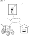
- FIG. 1 is a diagram providing an overview of an agriculture management system 1 according to an illustrative embodiment of the present disclosure.
- the agriculture management system 1 shown in FIG. 1 includes a work vehicle 100, a terminal device 400, and a management device 600.
- the terminal device 400 is a computer used by a user performing remote monitoring of the work vehicle 100.
- the management device 600 is a computer managed by a business operator running the agriculture management system 1.
- the work vehicle 100, the terminal device 400 and the management device 600 can communicate with each other via the network 80.
- FIG. 1 shows one work vehicle 100, but the agriculture management system 1 may include a plurality of the work vehicles or any other agricultural machine.
- the work vehicle 100 is a tractor.
- the work vehicle 100 can have an implement attached to its rear and/or its front. While performing agricultural work in accordance with the type of the implement, the work vehicle 100 is able to travel inside a field.
- the work vehicle 100 may travel inside the field or outside the field with no implement being attached thereto.
- the work vehicle 100 has a self-driving function. In other words, the work vehicle 100 can travel by the action of a controller, rather than manually.
- the controller according to the present embodiment is provided inside the work vehicle 100, and is able to control both the speed and steering of the work vehicle 100.
- the work vehicle 100 can perform self-traveling outside the field (e.g., on roads) as well as inside the field.
- the work vehicle 100 includes a device usable for positioning or localization, such as a GNSS receiver or an LiDAR sensor. Based on the position of the work vehicle 100 and information on a target path, the controller of the work vehicle 100 causes the work vehicle 100 to automatically travel. In addition to controlling the travel of the work vehicle 100, the controller also controls the operation of the implement. As a result, while automatically traveling inside the field, the work vehicle 100 is able to perform agricultural work by using the implement. In addition, the work vehicle 100 is able to automatically travel along the target path on a road outside the field (e.g., an agricultural road or a general road). The work vehicle 100 travels in a self-traveling mode along roads outside the field with the effective use of data output from sensing devices, such as the cameras 120, the obstacle sensors 130 and the LiDAR sensor 140.
- sensing devices such as the cameras 120, the obstacle sensors 130 and the LiDAR sensor 140.
- the management device 600 is a computer to manage the agricultural work performed by the work vehicle 100.
- the management device 600 may be, for example, a server computer that performs centralized management on information regarding the field on the cloud and supports agriculture by use of the data on the cloud.
- the management device 600 for example, creates a work plan for the work vehicle 100 and causes the work vehicle 100 to execute agricultural work in accordance with the work plan.
- the management device 600 generates a target path in the field based on, for example, the information entered by a user using the terminal unit 400 or any other device.
- the management device 600 may generate and edit an environment map based on data collected by the work vehicle 100 or any other movable body by use of the sensing device such as a LiDAR sensor.
- the management device 600 transmits data on the work plan, the target path and the environment map thus generated to the work vehicle 100.
- the work vehicle 100 automatically moves and performs agricultural work based on the data.
- the terminal device 400 is a computer that is used by a user who is at a remote place from the work vehicle 100.
- the terminal device 400 shown in FIG. 1 is a laptop computer, but the terminal device 400 is not limited to this.
- the terminal device 400 may be a stationary computer such as a desktop PC (personal computer), or a mobile terminal such as a smartphone or a tablet computer.
- the terminal device 400 may be used to perform remote monitoring of the work vehicle 100 or remote-manipulate the work vehicle 100.
- the terminal device 400 can display, on a display screen thereof, a video captured by one or more cameras (imagers) included in the work vehicle 100.
- the terminal device 400 can also display, on the display screen thereof, a setting screen allowing the user to input information necessary to create a work plan (e.g., a schedule of each task of agricultural work) for the work vehicle 100.
- a work plan e.g., a schedule of each task of agricultural work
- the terminal device 400 transmits the input information to the management device 600.
- the management device 600 creates a work plan based on the information.
- the terminal device 400 may further have a function of displaying, on a display screen thereof, a setting screen allowing the user to input information necessary to set a target path.
- FIG. 2 is a side view schematically showing an example of the work vehicle 100 and an example of implement 300 linked to the work vehicle 100.
- the work vehicle 100 according to the present embodiment can operate both in a manual driving mode and a self-driving mode. In the self-driving mode, the work vehicle 100 is able to perform unmanned travel. The work vehicle 100 can perform self-driving both inside a field and outside the field.
- the work vehicle 100 includes a vehicle body 101, a prime mover (engine) 102, and a transmission 103.
- wheels 104 with tires and a cabin 105 are provided on the vehicle body 101.
- the wheels 104 include a pair of front wheels 104F and a pair of rear wheels 104R.
- a driver's seat 107, a steering device 106, an operational terminal 200, and switches for manipulation are provided inside the cabin 105.
- either or both of the front wheels 104F and the rear wheels 104R may be a plurality of wheels (crawlers) with a continuous track rather than wheels with tires.
- the work vehicle 100 can include at least one sensing device to sense the environment around the work vehicle 100 and a processing unit to process sensor data output from the at least one sensing device.
- the work vehicle 100 includes a plurality of sensing devices.
- the sensing devices include a plurality of cameras 120, a LiDAR sensor 140, and a plurality of obstacle sensors 130.
- the cameras 120 may be provided at the front/rear/right/left of the work vehicle 100, for example.
- the cameras 120 image the environment around the work vehicle 100 and generate image data.
- the images acquired by the cameras 120 can be output to a processing unit included in the work vehicle 100 and transmitted to the terminal device 400, which is responsible for remote monitoring. Also, the images may be used to monitor the work vehicle 100 during unmanned driving.
- the cameras 120 may also be used to generate images to allow the work vehicle 100, traveling on a road outside the field (an agricultural road or a general road), to recognize objects, obstacles, white lines, road signs, traffic signs or the like in the surroundings of the work vehicle 100.
- the LiDAR sensor 140 in the example shown in FIG. 2 is disposed on a bottom portion of a front surface of the vehicle body 101.
- the LiDAR sensor 140 may be disposed at any other position.
- the LiDAR sensor 140 may be provided at the upper portion of the cabin 105.
- the LiDAR sensor 140 can be a 3D-LiDAR sensor but may be a 2D-LiDAR sensor.
- the LiDAR sensor 140 senses the environment around the work vehicle 100 to output sensor data. While the work vehicle 100 is traveling mainly outside the field, the LiDAR sensor 140 repeatedly outputs sensor data representing the distance and the direction between an object existing in the environment around the work vehicle 100 and each of measurement points, or three-dimensional or two-dimensional coordinate values of each of the measurement points.
- the sensor data output from the LiDAR sensor 140 is processed by the controller of the work vehicle 100.
- the controller can perform localization of the work vehicle 100 by matching the sensor data against the environment map.
- the controller can further detect an object such as an obstacle existing in the surroundings of the work vehicle 100 based on the sensor data.
- the controller can utilize an algorithm such as, for example, SLAM (Simultaneous Localization and Mapping) to generate or edit an environment map.
- the work vehicle 100 may include a plurality of LiDAR sensors disposed at different positions with different orientations.
- the plurality of obstacle sensors 130 shown in FIG. 2 are provided at the front and the rear of the cabin 105.
- the obstacle sensors 130 may be disposed at other positions.
- one or more obstacle sensors 130 may be disposed at any position at the sides, the front or the rear of the vehicle body 101.
- the obstacle sensors 130 may include, for example, a laser scanner or an ultrasonic sonar.
- the obstacle sensors 130 may be used to detect obstacles around the work vehicle 100 during self-traveling to cause the work vehicle 100 to halt or detour around the obstacles.
- the LiDAR sensor 140 may be used as one of the obstacle sensors 130.
- the work vehicle 100 further includes a GNSS unit 110.
- the GNSS unit 110 includes a GNSS receiver.
- the GNSS receiver may include an antenna to receive a signal(s) from a GNSS satellite(s) and a processor to calculate the position of the work vehicle 100 based on the signal(s) received by the antenna.
- the GNSS unit 110 receives satellite signals transmitted from the plurality of GNSS satellites, and performs positioning based on the satellite signals.
- GNSS is the general term for satellite positioning systems such as GPS (Global Positioning System), QZSS (Quasi-Zenith Satellite System; e.g., MICHIBIKI), GLONASS, Galileo, and BeiDou.
- GPS Global Positioning System
- QZSS Quadasi-Zenith Satellite System
- GLONASS Galileo
- BeiDou BeiDou.
- the GNSS unit 110 may include an inertial measurement unit (IMU). Signals from the IMU can be used to complement position data.
- the IMU can measure a tilt or a small motion of the work vehicle 100.
- the data acquired by the IMU can be used to complement the position data based on the satellite signals, so as to improve the performance of positioning.
- the controller of the work vehicle 100 may utilize, for positioning, the sensor data acquired by the sensing devices such as the cameras 120 and/or the LIDAR sensor 140, in addition to the positioning results provided by the GNSS unit 110.
- the position and the orientation of the work vehicle 100 can be estimated with a high accuracy based on data that is acquired by the cameras 120 and/or the LiDAR sensor 140 and on an environment map that is previously stored in the storage device.
- By correcting or complementing position data based on the satellite signals using the data acquired by the cameras 120 and/or the LiDAR sensor 140 it becomes possible to identify the position of the work vehicle 100 with a higher accuracy.
- the prime mover 102 may be a diesel engine, for example. Instead of a diesel engine, an electric motor may be used.
- the transmission 103 can change the propulsion and the moving speed of the work vehicle 100 through a speed changing mechanism.
- the transmission 103 can also switch between forward travel and backward travel of the work vehicle 100.
- the steering device 106 includes a steering wheel, a steering shaft connected to the steering wheel, and a power steering device to assist in the steering by the steering wheel.
- the front wheels 104F are the steered wheels, such that changing their angle of turn (also referred to as "steering angle") can cause a change in the traveling direction of the work vehicle 100.
- the steering angle of the front wheels 104F can be changed by manipulating the steering wheel.
- the power steering device includes a hydraulic device or an electric motor to supply an assisting force to change the steering angle of the front wheels 104F.
- the steering angle may be automatically adjusted by the power of the hydraulic device or the electric motor.
- a linkage device 108 is provided at the rear of the vehicle body 101.
- the linkage device 108 includes, e.g., a three-point linkage (also referred to as a "three-point link” or a "three-point hitch"), a PTO (Power Take Off) shaft, a universal joint, and a communication cable.
- the linkage device 108 allows the implement 300 to be attached to, or detached from, the work vehicle 100.
- the linkage device 108 is able to raise or lower the three-point link with a hydraulic device, for example, thus changing the position and/or attitude of the implement 300.
- motive power can be sent from the work vehicle 100 to the implement 300 via the universal joint. While towing the implement 300, the work vehicle 100 allows the implement 300 to perform a predetermined task.
- the linkage device may be provided at the front portion of the vehicle body 101. In that case, the implement 300 can be connected with the front portion of the work vehicle 100.
- the implement 300 shown in FIG. 2 is a rotary tiller
- the implement 300 is not limited to a rotary tiller.
- any arbitrary implement such as a seeder, a spreader, a transplanter, a mower, a rake implement, a baler, a harvester, a sprayer, or a harrow, can be connected to the work vehicle 100 for use.
- the work vehicle 100 shown in FIG. 2 can be driven by human driving; alternatively, it may only support unmanned driving. In that case, component elements which are only required for human driving, e.g., the cabin 105, the steering device 106, and the driver's seat 107 do not need to be provided in the work vehicle 100.
- An unmanned work vehicle 100 can travel via autonomous driving, or by remote operation by a user.
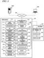
- FIG. 3 is a block diagram showing an example configuration of the work vehicle 100 and the implement 300.
- the work vehicle 100 and the implement 300 can communicate with each other via a communication cable that is included in the linkage device 108.
- the work vehicle 100 is able to communicate with the terminal device 400 and the management device 600 via the network 80.
- the work vehicle 100 in the example of FIG. 3 includes sensors 150 to detect the operating status of the work vehicle 100, a control system 160, a communication device 190, operation switches 210, a buzzer 220, and a drive device 240. These component elements are communicably connected to each other via a bus.
- the GNSS unit 110 includes a GNSS receiver 111, an RTK receiver 112, an inertial measurement unit (IMU) 115, and a processing circuit 116.
- the sensors 150 include a steering wheel sensor 152, an angle-of-turn sensor 154, and an axle sensor 156.
- the control system 160 includes a processing unit 161, a storage device 170 and a controller 180.
- the controller 180 includes a plurality of electronic control units (ECU) 181 to 185.
- the implement 300 includes a drive device 340, a controller 380, and a communication device 390. Note that FIG. 3 shows component elements which are relatively closely related to the operations of self-driving by the work vehicle 100, while other components are omitted from illustration.
- the GNSS receiver 111 in the GNSS unit 110 receives satellite signals transmitted from the plurality of GNSS satellites and generates GNSS data based on the satellite signals.
- the GNSS data is generated in a predetermined format such as, for example, the NMEA-0183 format.
- the GNSS data may include, for example, the identification number, the angle of elevation, the azimuth angle, and a value representing the reception strength of each of the satellites from which the satellite signals are received.
- the GNSS unit 110 shown in FIG. 3 performs positioning of the work vehicle 100 by utilizing an RTK (Real Time Kinematic) -GNSS.
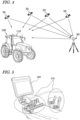
- FIG. 4 is a conceptual diagram showing an example of the work vehicle 100 performing positioning based on the RTK-GNSS.
- the reference station 60 may be disposed near the field where the work vehicle 100 performs tasked travel (e.g., at a position within 10 km of the work vehicle 100).
- the position of the work vehicle 100 is estimated by another method with no use of the signal from the RTK receiver 112.
- the position of the work vehicle 100 may be estimated by matching the data output from the LiDAR sensor 140 and/or the cameras 120 against a highly accurate environment map.
- the GNSS unit 110 further includes the IMU 115.
- the IMU 115 may include a 3-axis accelerometer and a 3-axis gyroscope.
- the IMU 115 may include a direction sensor such as a 3-axis geomagnetic sensor.
- the IMU 115 functions as a motion sensor which can output signals representing parameters such as acceleration, velocity, displacement, and attitude of the work vehicle 100.
- the processing circuit 116 can estimate the position and orientation of the work vehicle 100 with a higher accuracy.
- the signal that is output from the IMU 115 may be used for the correction or complementation of the position that is calculated based on the satellite signals and the correction signal.
- the IMU 115 outputs a signal more frequently than the GNSS receiver 111. Utilizing this signal that is output highly frequently, the processing circuit 116 allows the position and orientation of the work vehicle 100 to be measured more frequently (e.g., about 10 Hz or above). Instead of the IMU 115, a 3-axis accelerometer and a 3-axis gyroscope may be separately provided. The IMU 115 may be provided as a separate device from the GNSS unit 110.
- the cameras 120 are imagers that image the environment around the work vehicle 100.
- Each of the cameras 120 includes an image sensor such as a CCD (Charge Coupled Device) or a CMOS (Complementary Metal Oxide Semiconductor), for example.
- each camera 120 may include an optical system including one or more lenses and a signal processing circuit.
- the cameras 120 image the environment around the work vehicle 100, and generate image data (e.g., motion picture data).
- the cameras 120 are able to capture motion pictures at a frame rate of 3 frames/second (fps: frames per second) or greater, for example.
- the images generated by the cameras 120 may be used by a remote supervisor to check the environment around the work vehicle 100 with the terminal device 400, for example.
- the images generated by the cameras 120 may also be used for the purpose of positioning and/or detection of obstacles.
- the plurality of cameras 120 may be provided at different positions on the work vehicle 100, or a single camera 120 may be provided.
- a visible camera(s) to generate visible light images and an infrared camera(s) to generate infrared images may be separately provided. Both of a visible camera(s) and an infrared camera(s) may be provided as cameras for generating images for monitoring purposes.
- the infrared camera(s) may also be used for detection of obstacles at nighttime.
- the obstacle sensors 130 detect objects existing around the work vehicle 100.
- Each of the obstacle sensors 130 may include a laser scanner or an ultrasonic sonar, for example.
- the obstacle sensor 130 When an object exists at a position within a predetermined distance from one of the obstacle sensors 130, the obstacle sensor 130 outputs a signal indicating the presence of the obstacle.
- the plurality of obstacle sensors 130 may be provided at different positions on the work vehicle 100.
- a plurality of laser scanners and a plurality of ultrasonic sonars may be disposed at different positions on the work vehicle 100. Providing such a great number of obstacle sensors 130 can reduce blind spots in monitoring obstacles around the work vehicle 100.
- the steering wheel sensor 152 measures the angle of rotation of the steering wheel of the work vehicle 100.
- the angle-of-turn sensor 154 measures the angle of turn of the front wheels 104F, which are the steered wheels. Measurement values by the steering wheel sensor 152 and the angle-of-turn sensor 154 are used for steering control by the controller 180.
- the axle sensor 156 measures the rotational speed, i.e., the number of revolutions per unit time, of an axle that is connected to the wheels 104.
- the axle sensor 156 may be a sensor including a magnetoresistive element (MR), a Hall generator, or an electromagnetic pickup, for example.
- the axle sensor 156 outputs a numerical value indicating the number of revolutions per minute (unit: rpm) of the axle, for example.
- the axle sensor 156 is used to measure the speed of the work vehicle 100.
- the buzzer 220 is an audio output device to present an alarm sound to alert the user of an abnormality.
- the buzzer 220 may present an alarm sound when an obstacle is detected during self-driving.
- the buzzer 220 is controlled by the controller 180.
- the processing unit 161 may be a microprocessor or a microcontroller.
- the processing unit 161 processes sensor data output from sensing devices, such as the cameras 120, the obstacle sensors 130 and the LiDAR sensor 140.
- the processing unit 161 detects objects around the work vehicle 100 based on data output from the cameras 120, the obstacle sensors 130 and the LiDAR sensor 140.
- the storage device 170 includes one or more storage mediums such as a flash memory or a magnetic disc.
- the storage device 170 stores various data that is generated by the GNSS unit 110, the cameras 120, the obstacle sensors 130, the LiDAR sensor 140, the sensors 150, and the controller 180.
- the data that is stored by the storage device 170 may include map data on the environment where the work vehicle 100 travels (environment map) and data on a target path for self-driving.
- the environment map includes information on a plurality of fields where the work vehicle 100 performs agricultural work and roads around the fields.
- the environment map and the target path may be generated by a processor in the management device 600.
- the controller 180 may have a function of generating or editing an environment map and a target path.
- the controller 180 can edit the environment map and the target path, acquired from the management device 600, in accordance with the environment where the work vehicle 100 travels.
- the storage device 170 also stores data on a work plan received by the communication device 190 from the management device 600
- the storage device 170 also stores a computer program(s) to cause the processing unit 161 and each of the ECUs in the controller 180 to perform various operations described below.
- a computer program(s) may be provided to the work vehicle 100 via a storage medium (e.g., a semiconductor memory, an optical disc, etc.) or through telecommunication lines (e.g., the Internet).
- a storage medium e.g., a semiconductor memory, an optical disc, etc.
- telecommunication lines e.g., the Internet
- Such a computer program(s) may be marketed as commercial software.
- the controller 180 includes the plurality of ECUs.
- the plurality of ECUs include, for example, the ECU 181 for speed control, the ECU 182 for steering control, the ECU 183 for implement control, the ECU 184 for self-driving control, and the ECU 185 for path generation.
- the ECU 181 controls the prime mover 102, the transmission 103 and brakes included in the drive device 240, thus controlling the speed of the work vehicle 100.
- the ECU 182 controls the hydraulic device or the electric motor included in the steering device 106 based on a measurement value of the steering wheel sensor 152, thus controlling the steering of the work vehicle 100.
- the ECU 183 controls the operations of the three-point link, the PTO shaft and the like that are included in the linkage device 108. Also, the ECU 183 generates a signal to control the operation of the implement 300, and transmits this signal from the communication device 190 to the implement 300.
- the ECU 184 Based on data output from the GNSS unit 110, the cameras 120, the obstacle sensors 130, the LiDAR sensor 140, the sensors 150 and the processing unit 161, the ECU 184 performs computation and control for achieving self-driving. For example, the ECU 184 specifies the position of the work vehicle 100 based on the data output from at least one of the GNSS unit 110, the cameras 120 and the LiDAR sensor 140. Inside the field, the ECU 184 may determine the position of the work vehicle 100 based only on the data output from the GNSS unit 110. The ECU 184 may estimate or correct the position of the work vehicle 100 based on the data acquired by the cameras 120 and/or the LiDAR sensor 140.
- the ECU 184 estimates the position of the work vehicle 100 by use of the data output from the LiDAR sensor 140 and/or the cameras 120. For example, the ECU 184 may estimate the position of the work vehicle 100 by matching the data output from the LiDAR sensor 140 and/or the cameras 120 against the environment map. During self-driving, the ECU 184 performs computation necessary for the work vehicle 100 to travel along a target path, based on the estimated position of the work vehicle 100. The ECU 184 sends the ECU 181 a command to change the speed, and sends the ECU 182 a command to change the steering angle.
- the ECU 181 controls the prime mover 102, the transmission 103 or the brakes to change the speed of the work vehicle 100.
- the ECU 182 controls the steering device 106 to change the steering angle.
- the ECU 185 can determine a destination of the work vehicle 100 based on the work plan stored in the storage device 170, and determine a target path from a beginning point to a target point of the movement of the work vehicle 100.
- the ECU 185 may perform the process of detecting objects around the work vehicle 100 based on the data output from the cameras 120, the obstacle sensors 130 and the LiDAR sensor 140.
- the controller 180 realizes self-driving.
- the controller 180 controls the drive device 240 based on the measured or estimated position of the work vehicle 100 and on the target path. As a result, the controller 180 can cause the work vehicle 100 to travel along the target path.
- the plurality of ECUs included in the controller 180 can communicate with each other in accordance with a vehicle bus standard such as, for example, a CAN (Controller Area Network). Instead of the CAN, faster communication methods such as Automotive Ethernet (registered trademark) may be used.
- a vehicle bus standard such as, for example, a CAN (Controller Area Network).
- CAN Controller Area Network
- faster communication methods such as Automotive Ethernet (registered trademark) may be used.
- the ECUs 181 to 185 are illustrated as individual blocks in FIG. 3 , the function of each of the ECU 181 to 185 may be implemented by a plurality of ECUs. Alternatively, an onboard computer that integrates the functions of at least some of the ECUs 181 to 185 may be provided.
- the controller 180 may include ECUs other than the ECUs 181 to 185, and any number of ECUs may be provided in accordance with functionality.
- Each ECU includes a processing circuit including one or more processors.
- the controller 180 may include
- the communication device 190 is a device including a circuit communicating with the implement 300, the terminal device 400 and the management device 600.
- the communication device 190 includes circuitry to perform exchanges of signals complying with an ISOBUS standard such as ISOBUS-TIM, for example, between itself and the communication device 390 of the implement 300. This allows the implement 300 to perform a desired operation, or allows information to be acquired from the implement 300.
- the communication device 190 may further include an antenna and a communication circuit to exchange signals via the network 80 with communication devices of the terminal device 400 and the management device 600.
- the network 80 may include a 3G, 4G, 5G, or any other cellular mobile communications network and the Internet, for example.
- the communication device 190 may have a function of communicating with a mobile terminal that is used by a supervisor who is situated near the work vehicle 100. With such a mobile terminal, communication may be performed based on any arbitrary wireless communication standard, e.g., Wi-Fi (registered trademark), 3G, 4G, 5G or any other cellular mobile communication standard, or Bluetooth (registered trademark).
- Wi-Fi registered trademark
- 3G, 4G, 5G any other cellular mobile communication standard
- Bluetooth registered trademark
- the operational terminal 200 is a terminal for the user to perform a manipulation related to the travel of the work vehicle 100 and the operation of the implement 300, and is also referred to as a virtual terminal (VT).
- the operational terminal 200 may include a display device such as a touch screen panel, and/or one or more buttons.
- the display device may be a display such as a liquid crystal display or an organic light-emitting diode (OLED) display, for example.
- OLED organic light-emitting diode
- the operational terminal 200 may be configured so as to be detachable from the work vehicle 100.
- a user who is at a remote place from the work vehicle 100 may manipulate the detached operational terminal 200 to control the operation of the work vehicle 100.
- the user may manipulate a computer on which necessary application software is installed, for example, the terminal device 400, to control the operation of the work vehicle 100.
- FIG. 5 is a diagram showing an example of the operational terminal 200 and an example of the operation switches 210 both provided in the cabin 105.
- the operation switches 210 including a plurality of switches that are manipulable to the user, are disposed.
- the operation switches 210 may include, for example, a switch to select the gear shift as to a main gear shift or a range gear shift, a switch to switch between a self-driving mode and a manual driving mode, a switch to switch between forward travel and backward travel, a switch to raise or lower the implement 300, and the like.
- the work vehicle 100 does not need to include the operation switches 210.
- the drive device 340 in the implement 300 shown in FIG. 3 performs operations necessary for the implement 300 to perform predetermined work.
- the drive device 340 includes a device suitable for uses of the implement 300, for example, a hydraulic device, an electric motor, a pump or the like.
- the controller 380 controls the operation of the drive device 340.
- the controller 380 causes the drive device 340 to perform various operations.
- a signal that is in accordance with the state of the implement 300 can be transmitted from the communication device 390 to the work vehicle 100.
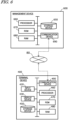
- FIG. 6 is a block diagram showing an example of schematic hardware configuration of the management device 600 and the terminal device 400.
- the management device 600 includes a storage device 650, a processor 660, a ROM (Read Only Memory) 670, a RAM (Random Access Memory) 680, and a communication device 690. These component elements are communicably connected to each other via a bus.
- the management device 600 may function as a cloud server to manage the schedule of the agricultural work to be performed by the work vehicle 100 in a field and support agriculture by use of the data managed by the management device 600 itself.
- the user can input information necessary to create a work plan by use of the terminal device 400 and upload the information to the management device 600 via the network 80.
- the management device 600 can create a schedule of agricultural work, that is, a work plan based on the information.
- the management device 600 can further generate or edit an environment map.
- the environment map may be distributed from a computer external to the management device 600.
- the processor 660 may be, for example, a semiconductor integrated circuit including a central processing unit (CPU).
- the processor 660 may be realized by a microprocessor or a microcontroller.
- the processor 660 may be realized by an FPGA (Field Programmable Gate Array), a GPU (Graphics Processing Unit), an ASIC (Application Specific Integrated Circuit) or an ASSP (Application Specific Standard Product) each including a CPU, or a combination of two or more selected from these circuits.
- the processor 660 consecutively executes a computer program, describing commands to execute at least one process, stored in the ROM 670 and thus realizes a desired process.
- the ROM 670 is, for example, a writable memory (e.g., PROM), a rewritable memory (e.g., flash memory) or a memory which can only be read from but cannot be written to.
- the ROM 670 stores a program to control operations of the processor 660.
- the ROM 670 does not need to be a single storage medium, and may be an assembly of a plurality of storage mediums. A portion of the assembly of the plurality of storage memories may be a detachable memory.
- the RAM 680 provides a work area in which the control program stored in the ROM 670 is once developed at the time of boot.
- the RAM 680 does not need to be a single storage medium, and may be an assembly of a plurality of storage mediums.
- the storage device 650 mainly functions as a storage for a database.
- the storage device 650 may be, for example, a magnetic storage device or a semiconductor storage device.
- An example of the magnetic storage device is a hard disc drive (HDD).
- An example of the semiconductor storage device is a solid state drive (SSD).
- the storage device 650 may be a device independent from the management device 600.
- the storage device 650 may be a storage device connected to the management device 600 via the network 80, for example, a cloud storage.
- the terminal device 400 includes an input device 420, a display device 430, a storage device 450, a processor 460, a ROM 470, a RAM 480, and a communication device 490. These component elements are communicably connected to each other via a bus.
- the input device 420 is a device to convert an instruction from the user into data and input the data to a computer.
- the input device 420 may be, for example, a keyboard, a mouse or a touch panel.
- the display device 430 may be, for example, a liquid crystal display or an organic EL display.
- the processor 460, the ROM 470, the RAM 480, the storage device 450 and the communication device 490 are substantially the same as the corresponding component elements described above regarding the example of the hardware configuration of the management device 600, and will not be described in repetition.
- the work vehicle 100 can automatically travel both inside and outside a field.
- the work vehicle 100 drives the implement 300 to perform predetermined agricultural work while traveling along a preset target path.
- the work vehicle 100 halts traveling and performs operations of presenting an alarm sound from the buzzer 220, transmitting an alert signal to the terminal device 400 and the like.
- the positioning of the work vehicle 100 is performed based mainly on data output from the GNSS unit 110.
- the work vehicle 100 automatically travels along a target path set for an agricultural road or a general road outside the field.
- the work vehicle 100 While traveling outside the field, the work vehicle 100 travels with the effective use of data acquired by the cameras 120 and/or the LiDAR sensor 140. When an obstacle is detected outside the field, the work vehicle 100 avoids the obstacle or halts at the point. Outside the field, the position of the work vehicle 100 is estimated based on data output from the LiDAR sensor 140 and/or the cameras 120 in addition to positioning data output from the GNSS unit 110.
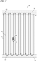
- FIG. 7 is a diagram schematically showing an example of the work vehicle 100 automatically traveling along a target path in a field.
- the field 70 includes a work area 72, in which the work vehicle 100 performs work by using the implement 300, and headlands 74, which are located near outer edges of the field 70. The user may previously specify which regions of the field 70 on the map would correspond to the work area 72 and the headlands 74.
- the target path in this example includes a plurality of main paths P1 parallel to each other and a plurality of turning paths P2 interconnecting the plurality of main paths P1 .
- the main paths P1 are located in the work area 72, whereas the turning paths P2 are located in the headlands 74.
- each main path P1 may also include a curved portion(s).
- Broken lines in FIG. 7 depict the working breadth of the implement 300.
- the working breadth is previously set and recorded in the storage device 170.
- the working breadth may be set and recorded by the user manipulating the operational terminal 200 or the terminal device 400. Alternatively, the working breadth may be automatically recognized and recorded when the implement 300 is connected to the work vehicle 100.
- the interval between the plurality of main paths P1 may be set so as to be matched to the working breadth.
- the target path may be generated based on the manipulation made by the user, before self-driving is begun.
- the target path may be generated so as to cover the entire work area 72 in the field 70, for example.
- the work vehicle 100 automatically travels while repeating a reciprocating motion from a beginning point of work to an ending point of work. Note that the target path shown in FIG. 7 is merely an example, and the target path may be arbitrarily determined.
- FIG. 8 is a flowchart showing an example operation of steering control to be performed by the controller 180 during self-driving.
- the controller 180 performs automatic steering by performing the operation from steps S121 to S125 shown in FIG. 8 .
- the speed of the work vehicle 100 will be maintained at a previously-set speed, for example.
- the controller 180 acquires data representing the position of the work vehicle 100 that is generated by the GNSS unit 110 (step S121).
- the controller 180 calculates a deviation between the position of the work vehicle 100 and the target path (step S122). The deviation represents the distance between the position of the work vehicle 100 and the target path at that moment.
- the controller 180 determines whether the calculated deviation in position exceeds the previously-set threshold or not (step S123). If the deviation exceeds the threshold, the controller 180 changes a control parameter of the steering device included in the drive device 240 so as to reduce the deviation, thus changing the steering angle (step S124). If the deviation does not exceed the threshold at step S123, the operation of step S124 is omitted. At the following step S125, the controller 180 determines whether a command to end the operation has been received or not. The command to end the operation may be given when the user has instructed that self-driving be suspended through remote operations, or when the work vehicle 100 has arrived at the destination, for example.
- step S121 the control returns to step S121 and the controller 180 performs substantially the same operation based on a newly measured position of the work vehicle 100.
- the controller 180 repeats the operation from steps S121 to S125 until a command to end the operation is given.
- the aforementioned operation is executed by the ECUs 182 and 184 in the controller 180.
- the controller 180 controls the drive device 240 based only on the deviation between the position of the work vehicle 100 as identified by the GNSS unit 110 and the target path.
- a deviation in terms of directions may further be considered in the control.
- the controller 180 may change the control parameter of the steering device of the drive device 240 (e.g., steering angle) in accordance with the deviation.
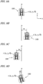
- FIG. 9A is a diagram showing an example of the work vehicle 100 traveling along a target path P.
- FIG. 9B is a diagram showing an example of the work vehicle 100 at a position which is shifted rightward from the target path P.
- FIG. 9C is a diagram showing an example of the work vehicle 100 at a position which is shifted leftward from the target path P.
- FIG. 9D is a diagram showing an example of the work vehicle 100 oriented in an inclined direction with respect to the target path P.
- the pose, i.e., the position and orientation, of the work vehicle 100 as measured by the GNSS unit 110 is expressed as r(x,y, ⁇ ).
- (x,y) are coordinates representing the position of a reference point on the work vehicle 100 in an XY coordinate system, which is a two-dimensional coordinate system fixed to the globe.
- the reference point on the work vehicle 100 is at a position, on the cabin, where a GNSS antenna is disposed, but the reference point may be at any arbitrary position.
- ⁇ is an angle representing the measured orientation of the work vehicle 100.
- the target path P is shown parallel to the Y axis in the examples illustrated in these figures, the target path P may not necessarily be parallel to the Y axis, in general.
- the controller 180 maintains the steering angle and speed of the work vehicle 100 without changing them.
- the controller 180 changes the steering angle so that the traveling direction of the work vehicle 100 will be inclined leftward, thus bringing the work vehicle 100 closer to the path P.
- the controller 180 changes the steering angle so that the traveling direction of the work vehicle 100 will be inclined leftward, thus bringing the work vehicle 100 closer to the path P.
- the magnitude of the steering angle may be adjusted in accordance with the magnitude of a positional deviation ⁇ x, for example.
- the controller 180 changes the steering angle so that the traveling direction of the work vehicle 100 will be inclined rightward, thus bringing the work vehicle 100 closer to the path P.
- the steering angle may be adjusted in accordance with the magnitude of the positional deviation ⁇ x, for example.
- the controller 180 changes the steering angle so that the directional deviation ⁇ will become smaller.
- the magnitude of the steering angle may be adjusted in accordance with the magnitudes of the positional deviation ⁇ x and the directional deviation ⁇ , for example. For instance, the amount of change of the steering angle (which is in accordance with the directional deviation ⁇ ) may be increased as the absolute value of the positional deviation ⁇ x decreases.
- the controller 180 halts the work vehicle 100. At this point, the controller 180 may cause the buzzer 220 to present an alarm sound or may transmit an alert signal to the terminal device 400. In the case where the obstacle is avoidable, the controller 180 may control the drive device 240 such that the obstacle is avoided.
- the work vehicle 100 can perform self-traveling outside a field as well as inside the field.
- the processing unit 161 and/or the controller 180 is able to detect objects around the work vehicle 100 (e.g., another vehicle, a pedestrian, etc.) based on data output from sensing devices such as the cameras 120, the obstacle sensors 130 and the LiDAR sensor 140.
- sensing devices such as the cameras 120, the obstacle sensors 130 and the LiDAR sensor 140.
- the controller 180 performs speed control and steering control such that the work vehicle 100 avoids the detected object, thereby realizing self-traveling on a road outside the field.
- FIG. 10 is a diagram schematically showing an example of state where a plurality of the work vehicles 100 are performing self-traveling inside a field 70 and on a road 76 outside the field 70.
- an environment map of a region including a plurality of fields 70 and roads around the fields 70, and a target path are recorded.
- the environment map and the target path may be generated by the management device 600 or the ECU 185.
- the work vehicle 100 travels along the target path while sensing the surroundings thereof by use of the sensing devices such as the cameras 120, the obstacle sensors 130 and the LiDAR sensor 140, with the implement 300 being raised.
- sensing devices such as the cameras 120, the obstacle sensors 130 and the LiDAR sensors 140, sense the environment around the work vehicle 100 to output sensor data.
- the work vehicle 100 of the present embodiment includes a travel control system 10 ( FIG. 3 ) configured to detect objects in the search region around the work vehicle 100 based on the sensor data and also control self-driving of the work vehicle 100.
- the travel control system 10 includes a control system 160, cameras 120, obstacle sensors 130 and LiDAR sensors 140.
- the control system 160 is also referred to as "controller”.
- the search region refers to part of a region around the work vehicle 100 sensed by the sensing devices in which a search for objects is to be conducted.
- the search region may be equal in size to, or may be smaller than, the sensing region sensed by the sensing devices.
- the search region can also be referred to as Region of Interest (ROI).
- the agriculture management system 1 may be the travel control system 10 configured to detect objects in the search region around the work vehicle 100 and also control self-driving of the work vehicle 100.
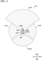
- FIG. 11 is a diagram showing an example of the search region 810 of the work vehicle 100.
- the search region 810 includes a front search region 810F, a rear search region 810Re, a left lateral search region 810L, and a right lateral search region 810R.
- FIG. 11 shows the search regions as viewed in plan from a vertical direction while the work vehicle 100 is on horizontal ground.
- the work vehicle 100 includes sensing devices 800.
- the sensing devices 800 the work vehicle 100 includes the sensing device 800F, 800Re, 800L, 800R.
- the sensing device 800F is provided in the front-side portion of the work vehicle 100 to mainly sense part of the surrounding environment extending on the front side of the work vehicle 100.
- the sensing device 800Re is provided in the rear-side portion of the work vehicle 100 to mainly sense part of the surrounding environment extending on the rear side of the work vehicle 100.
- the sensing device 800L is provided in the left-side portion of the work vehicle 100 to mainly sense part of the surrounding environment extending on the left side of the work vehicle 100.
- the sensing device 800R is provided in the right-side portion of the work vehicle 100 to mainly sense part of the surrounding environment extending on the right side of the work vehicle 100.
- the sensing devices 800Re, 800L, 800R can be provided in, for example, the cabin 105 of the work vehicle 100 ( FIG. 2 ).
- the sensing device 800Re may be provided in the implement 300.
- the search region 810 includes the front search region 810F, the rear search region 810Re, the left lateral search region 810L, and the right lateral search region 810R.
- the front search region 810F is a region in which detection of objects is performed using sensor data output from the sensing device 800F provided in the front-side portion of the work vehicle 100.
- the rear search region 810Re is a region in which detection of objects is performed using sensor data output from the sensing device 800Re provided in the rear-side portion of the work vehicle 100.
- the left lateral search region 810L is a region in which detection of objects is performed using sensor data output from the sensing device 800L provided in the left-side portion of the work vehicle 100.
- the right lateral search region 810R is a region in which detection of objects is performed using sensor data output from the sensing device 800R provided in the right-side portion of the work vehicle 100.
- the three-dimensional point cloud data output by the LiDAR sensors 140 includes the information about the position of a plurality of points and the information such as the reception intensity of a photodetector (attribute information).
- the information about the position of a plurality of points is, for example, the information about the emission direction of laser pulses corresponding to the points and the distance between the LiDAR sensors and the points.
- the information about the position of a plurality of points is the information about the coordinates of the points in a local coordinate system.
- the local coordinate system is a coordinate system that moves together with the work vehicle 100 and is also referred to as sensor coordinate system.
- the coordinates of each point can be calculated from the emission direction of laser pulses corresponding to the points and the distance between the LiDAR sensors and the points.
- the condition of the passageway 71 can be checked.
- the damage to the passageway 71 can be checked.
- the both sides of the passageway 71 with respect to the transverse direction are sensed by the sensing devices 800.
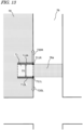
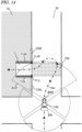
- the controller 180 controls the work vehicle 100 so as to travel along the target path 761 such that the both sides of the passageway 71 with respect to the transverse direction D1 are sensed.
- the regions 710R, 710L on the both sides of the passageway 71 with respect to the transverse direction D1, which include the boundaries 711R and 711L between the road 76 and the passageway 71, are sensed by the sensing devices 800.
- the left side as viewed from the road 76 toward the passageway 71 is referred to as the left side of the passageway 71
- the right side as viewed from the road 76 toward the passageway 71 is referred to as the right side of the passageway 71.
- the boundary 711R is the right end portion of the boundary between the road 76 and the passageway 71.
- the boundary 711L is the left end portion of the boundary between the road 76 and the passageway 71.
- the region 710R including the boundary 711R is a region that includes a right outer lateral portion of the passageway 71 extending along the advancing direction through the passageway 71.
- the region 710L including the boundary 711L is a region that includes a left outer lateral portion of the passageway 71 extending along the advancing direction through the passageway 71.
- the controller (control system) 160 causes the sensing devices 800 to sense the passageway 71 from a position away from the boundary 711L (left side boundary) between the road 76 and the passageway 71 in the leftward direction 720L.
- the target path 761 includes a path leading to the passageway 71 from a position away from the passageway 71 in the leftward direction 720L.
- the region 710L can be sensed using, for example, the sensing device 800F.
- the controller 160 also causes the sensing devices 800 to sense the passageway 71 from a position away from the boundary 711R (right side boundary) between the road 76 and the passageway 71 in the rightward direction 720R.
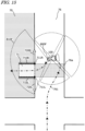
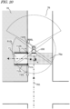
- the target path 761 includes a path along which the work vehicle 100 makes a turn under a condition where at least part of the work vehicle 100 has passed through an area 76a of the road 76 in front of the passageway 71.
- the area 76a is, for example, a region defined by a straight line extending from the boundary 711L across the road 76 in the transverse direction of the road 76, a straight line extending from the boundary 711R across the road 76 in the transverse direction of the road 76, and the opposite ends of the road 76 between the two straight lines.
- FIG. 15 is a diagram showing the work vehicle 100 that makes a left turn after having passed through the area 76a in front of the passageway 71 along the target path 761. Since the work vehicle 100 makes a left turn after having passed through the area 76a in front of the passageway 71, the region 710R can be sensed using, for example, the sensing device 800F.
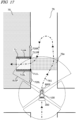
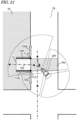
- FIG. 16 is a diagram showing the work vehicle 100 that makes a turn to enter the passageway 71 after having passed through the area 76a in front of the passageway 71.
- the passageway 71 and its surrounding environment can be checked in detail.
- the sensing devices 800 sense the passageway 71 from a position away from the boundary 711L in the leftward direction 720L, and the sensing devices 800 also sense the passageway 71 from a position away from the boundary 711R in the rightward direction 720R.
- the order of the sensing from the position away in the leftward direction 720L and the sensing from the position away in the rightward direction 720R is not particularly limited.
- the order of the sensing from the position away in the leftward direction 720L and the sensing from the position away in the rightward direction 720R can vary depending on whether the passageway 71 is on the left or right side of the road 76.
- the processing unit 161 of the controller 160 may determine whether or not to allow the work vehicle 100 to enter the passageway 71 based on the sensor data. If the controller 160 determines not to allow the work vehicle 100 to enter the passageway 71, the controller 160 controls the work vehicle 100 so as not to enter the passageway 71. For example, the controller 160 controls the work vehicle 100 so as to stop traveling. For example, the processing unit 161 compares the shape of the passageway 71 sensed at this time with the shape of the passageway 71 sensed in the past, and if the processing unit 161 determines that the change in shape is equal to or greater than a predetermined amount, the processing unit 161 may determine not to allow the work vehicle 100 to enter the passageway 71.
- the controller 160 may transmit at least part of the sensor data to an external device via the communication device 190.
- the external device is, for example, the terminal device 400 and/or the management device 600.
- the processor of the external device determines whether or not to allow the work vehicle 100 to enter the passageway 71 based on the sensor data. For example, the processor compares the shape of the passageway 71 sensed at this time with the shape of the passageway 71 sensed in the past, and if the processor determines that the change in shape is equal to or greater than a predetermined amount, the processor may determine not to allow the work vehicle 100 to enter the passageway 71.
- a person employed for monitoring the work using the external device may determine whether or not to allow the work vehicle 100 to enter the passageway 71 based on the sensor data.
- the person employed for monitoring the work determines not to allow the work vehicle 100 to enter the passageway 71
- the person inputs to the external device a command not to allow the work vehicle 100 to enter the passageway 71.
- the external device transmits to the work vehicle 100 information representing that the work vehicle 100 is not allowed to enter the passageway 71.
- controller 160 If the controller 160 receives from the external device the information representing that the work vehicle 100 is not allowed to enter the passageway 71, the controller 160 controls the work vehicle 100 so as not to enter the passageway 71.
- the work vehicle 100 may provide notification around the work vehicle 100 that the work vehicle 100 is going to make such a turn.
- the work vehicle 100 may include a notification device capable of emitting light and/or sound.
- the work vehicle 100 may use the notification device to provide notification around the work vehicle 100 that the work vehicle 100 is going to make a turn.
- the buzzer 220 may be used as the notification device. When the work vehicle 100 makes a turn, the buzzer 220 may emit an alarm sound.
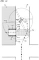
- FIG. 17 and FIG. 18 are diagrams showing another example of the target path 761.
- the target path 761 shown in FIG. 17 and FIG. 18 includes a path along which the work vehicle 100 makes a U turn after having passed through the area 76a of the road 76 in front of the passageway 71.
- the target path 761 includes a path leading to the passageway 71 from a position away from the passageway 71 in the leftward direction 720L.
- the region 710L can be sensed using, for example, the sensing device 800F.
- FIG. 18 illustrates the work vehicle 100 that makes a U-turn after having passed through the area 76a in front of the passageway 71 along the target path 761.
- the region 710R can be sensed using, for example, the sensing device 800F.
- FIG. 19 , FIG. 20 and FIG. 21 are diagrams showing still another example of the target path 761.
- the target path 761 shown in FIG. 19 , FIG. 20 and FIG. 21 includes a path along which the work vehicle 100 reverses after at least part of the work vehicle 100 traveling forward has passed through the area 76a of the road 76 in front of the passageway 71.
- the target path 761 includes a path leading to the passageway 71 from a position away from the passageway 71 in the leftward direction 720L.
- the region 710L can be sensed using, for example, the sensing device 800F.
- the region 710R can be sensed using, for example, the sensing device 800L.
- the work vehicle 100 reverses after at least part of the work vehicle 100 has passed through the area in front of the passageway 71.
- the work vehicle 100 makes a right turn while reversing, although the work vehicle 100 may reverse such that it travels backward in a straight line. Even if at least part of the work vehicle 100 has passed through the area in front of the passageway 71, the work vehicle 100 can reverse afterward so that the work vehicle 100 can easily enter the passageway 71.
- a target path 761 is described along which the work vehicle 100 exits from the field 70 into the road 76 via the passageway 71.
- FIG. 22 is a diagram showing the target path 761 along which the work vehicle 100 exits from the field 70 into the road 76 via the passageway 71.
- the passageway 71 is located on the right side of the field 70 as viewed from the advancing direction and, therefore, the work vehicle 100 turns right to enter the passageway 71 from the field 70.
- the controller 180 controls the work vehicle 100 so as to travel along the target path 761 such that the both sides of the passageway 71 with respect to the transverse direction D1 are sensed ( FIG. 13 ) .
- the regions 710R1, 710L1 on the both sides of the passageway 71 with respect to the transverse direction D1, which include the boundaries 711R1, 711L1 between the field 70 and the passageway 71, are sensed by the sensing devices 800.
- the left side as viewed from the field 70 toward the passageway 71 is referred to as the left side of the passageway 71
- the right side as viewed from the field 70 toward the passageway 71 is referred to as the right side of the passageway 71.
- the boundary 711R1 is the right end portion of the boundary between the field 70 and the passageway 71.
- the boundary 711L1 is the left end portion of the boundary between the field 70 and the passageway 71.
- the region 710R1 including the boundary 711R1 is a region that includes a right outer lateral portion of the passageway 71 extending along the advancing direction through the passageway 71.
- the region 710L1 including the boundary 711L1 is a region that includes a left outer lateral portion of the passageway 71 extending along the advancing direction through the passageway 71.
- the controller 160 causes the sensing devices 800 to sense the passageway 71 from a position away from the boundary 711R1 (right side boundary) between the field 70 and the passageway 71 in the rightward direction 720R1.
- the target path 761 includes a path leading to the passageway 71 from a position away from the passageway 71 in the rightward direction 720R1.
- the region 710R1 can be sensed using, for example, the sensing device 800F.
- the controller 160 also causes the sensing devices 800 to sense the passageway 71 from a position away from the boundary 711L1 (left side boundary) between the field 70 and the passageway 71 in the leftward direction 720L1.
- the target path 761 includes a path along which the work vehicle 100 makes a turn under a condition where at least part of the work vehicle 100 has passed through an area 71a of the field 70 in front of the passageway 71.
- the area 71a is, for example, a region defined by a straight line extending from the boundary 711L1 across the field 70 in parallel with the advancing direction through the passageway 71, a straight line extending from the boundary 711R1 across the field 70 in parallel with the advancing direction through the passageway 71, and the opposite ends of the field 70 between the two straight lines.
- FIG. 23 is a diagram showing the work vehicle 100 that makes a right turn after having passed through the area 71a in front of the passageway 71 along the target path 761. Since the work vehicle 100 makes a right turn after having passed through the area 71a in front of the passageway 71, the region 710L1 can be sensed using, for example, the sensing device 800F.
- the present disclosure includes travel control systems, travel control methods, and computer programs, which will be described below.
- a travel control system 10 for controlling self-driving of a work vehicle 100 comprising:
- a travel control method for controlling self-driving of a work vehicle 100 comprising:
- a computer program for instructing a computer to control self-driving of a work vehicle 100 the computer program instructing the computer to execute the followings:
- the techniques according to the present disclosure are particularly useful in the fields of agricultural machines, such as tractors, harvesters, rice transplanters, vehicles for crop management, vegetable transplanters, mowers, seeders, spreaders, or agricultural robots, for example.
Landscapes
- Life Sciences & Earth Sciences (AREA)
- Engineering & Computer Science (AREA)
- Mechanical Engineering (AREA)
- Soil Sciences (AREA)
- Environmental Sciences (AREA)
- Guiding Agricultural Machines (AREA)
Applications Claiming Priority (2)
| Application Number | Priority Date | Filing Date | Title |
|---|---|---|---|
| JP2022103755 | 2022-06-28 | ||
| PCT/JP2023/019522 WO2024004463A1 (ja) | 2022-06-28 | 2023-05-25 | 走行制御システム、走行制御方法およびコンピュータプログラム |
Publications (2)
| Publication Number | Publication Date |
|---|---|
| EP4548735A1 true EP4548735A1 (de) | 2025-05-07 |
| EP4548735A4 EP4548735A4 (de) | 2025-10-29 |
Family
ID=89382698
Family Applications (1)
| Application Number | Title | Priority Date | Filing Date |
|---|---|---|---|
| EP23830914.0A Pending EP4548735A4 (de) | 2022-06-28 | 2023-05-25 | Reisesteuerungssystem, reisesteuerungsverfahren und computerprogramm |
Country Status (4)
| Country | Link |
|---|---|
| US (1) | US20250143200A1 (de) |
| EP (1) | EP4548735A4 (de) |
| JP (1) | JPWO2024004463A1 (de) |
| WO (1) | WO2024004463A1 (de) |
Family Cites Families (14)
| Publication number | Priority date | Publication date | Assignee | Title |
|---|---|---|---|---|
| JP3814230B2 (ja) * | 2002-06-05 | 2006-08-23 | ヤンマー農機株式会社 | 農業用散布作業車 |
| JP2005176741A (ja) * | 2003-12-19 | 2005-07-07 | Yanmar Co Ltd | 農業用作業車 |
| WO2009078356A1 (ja) * | 2007-12-18 | 2009-06-25 | Honda Motor Co., Ltd. | 車両用駐車可否判定装置、車両用駐車スペース検出装置および車両用移動可能範囲検出装置 |
| WO2015118730A1 (ja) * | 2014-02-06 | 2015-08-13 | ヤンマー株式会社 | 併走作業システムの遠隔操作装置 |
| JP6727944B2 (ja) * | 2016-06-17 | 2020-07-22 | 株式会社クボタ | 圃場走行経路生成システム及び圃場作業車 |
| JP6739364B2 (ja) * | 2017-01-20 | 2020-08-12 | 株式会社クボタ | 自動走行作業車 |
| MX2019015353A (es) * | 2017-07-07 | 2020-02-07 | Nissan Motor | Metodo de asistencia al estacionamiento y dispositivo de control de estacionamiento. |
| JP6937263B2 (ja) * | 2018-03-26 | 2021-09-22 | ヤンマーパワーテクノロジー株式会社 | 作業車両の走行制御システム |
| JP6942664B2 (ja) | 2018-03-28 | 2021-09-29 | ヤンマーパワーテクノロジー株式会社 | 作業車両の走行制御システム |
| JP6832884B2 (ja) * | 2018-03-29 | 2021-02-24 | ヤンマーパワーテクノロジー株式会社 | 自動走行システム及び状況報知装置 |
| EP3823795A4 (de) * | 2018-07-16 | 2022-04-06 | Brain Corporation | Systeme und verfahren zur optimierung der routenplanung für enge wendungen für robotergeräte |
| KR102703729B1 (ko) * | 2018-10-16 | 2024-09-09 | 현대자동차주식회사 | 차량의 주차 지원 장치 및 방법 |
| US12122419B2 (en) * | 2020-06-25 | 2024-10-22 | Tusimple, Inc. | Two-level path planning for autonomous vehicles |
| JP7359106B2 (ja) * | 2020-08-14 | 2023-10-11 | 井関農機株式会社 | 作業車両の管理制御システム |
-
2023
- 2023-05-25 WO PCT/JP2023/019522 patent/WO2024004463A1/ja not_active Ceased
- 2023-05-25 JP JP2024530386A patent/JPWO2024004463A1/ja active Pending
- 2023-05-25 EP EP23830914.0A patent/EP4548735A4/de active Pending
-
2024
- 2024-12-26 US US19/001,703 patent/US20250143200A1/en active Pending
Also Published As
| Publication number | Publication date |
|---|---|
| JPWO2024004463A1 (de) | 2024-01-04 |
| US20250143200A1 (en) | 2025-05-08 |
| EP4548735A4 (de) | 2025-10-29 |
| WO2024004463A1 (ja) | 2024-01-04 |
Similar Documents
| Publication | Publication Date | Title |
|---|---|---|
| US20240302845A1 (en) | Path-planning system for self-driving agricultural machine | |
| US20240338037A1 (en) | Path planning system and path planning method for agricultural machine performing self-traveling | |
| US12509091B2 (en) | Agricultural road identification system, control system, and agricultural machine | |
| EP4445708B1 (de) | Hinderniserkennungssystem, landwirtschaftliche maschine und hinderniserkennungsverfahren | |
| US20240172577A1 (en) | Control system for agricultural machine and agriculture management system | |
| US20240345253A1 (en) | Agricultural machine, sensing system used in agricultural machine, and sensing method | |
| EP4510111A1 (de) | Kartenerzeugungssystem und routenplanungssystem | |
| US12585286B2 (en) | Map generation system and map generation method | |
| EP4538819A1 (de) | Nutzfahrzeug, steuerungsverfahren und steuerungssystem | |
| US20250089596A1 (en) | Agricultural management system | |
| EP4541163A1 (de) | Fahrsteuerungssystem, landwirtschaftliche maschine und fahrsteuerungsverfahren | |
| US20240138282A1 (en) | Management system for agricultural machines | |
| US12490664B2 (en) | Turning control for autonomous agricultural vehicle | |
| US20240337753A1 (en) | Agricultural machine, sensing system for use in agricultural machine, and sensing method | |
| US20250085432A1 (en) | Sensing system, agricultural machine, and sensing device | |
| JP7709409B2 (ja) | 農業機械の自動走行のための経路生成システムおよび経路生成方法 | |
| EP4548735A1 (de) | Reisesteuerungssystem, reisesteuerungsverfahren und computerprogramm | |
| EP4537645A1 (de) | Routenerzeugungssystem und routenerzeugungsverfahren zur automatisierten fahrt einer landwirtschaftlichen maschine |
Legal Events
| Date | Code | Title | Description |
|---|---|---|---|
| STAA | Information on the status of an ep patent application or granted ep patent |
Free format text: STATUS: THE INTERNATIONAL PUBLICATION HAS BEEN MADE |
|
| PUAI | Public reference made under article 153(3) epc to a published international application that has entered the european phase |
Free format text: ORIGINAL CODE: 0009012 |
|
| STAA | Information on the status of an ep patent application or granted ep patent |
Free format text: STATUS: REQUEST FOR EXAMINATION WAS MADE |
|
| 17P | Request for examination filed |
Effective date: 20250128 |
|
| AK | Designated contracting states |
Kind code of ref document: A1 Designated state(s): AL AT BE BG CH CY CZ DE DK EE ES FI FR GB GR HR HU IE IS IT LI LT LU LV MC ME MK MT NL NO PL PT RO RS SE SI SK SM TR |
|
| DAV | Request for validation of the european patent (deleted) | ||
| DAX | Request for extension of the european patent (deleted) | ||
| A4 | Supplementary search report drawn up and despatched |
Effective date: 20250925 |
|
| RIC1 | Information provided on ipc code assigned before grant |
Ipc: A01B 69/00 20060101AFI20250919BHEP Ipc: G05D 1/20 20240101ALI20250919BHEP |