EP4548733A1 - A weeding tool - Google Patents
A weeding tool Download PDFInfo
- Publication number
- EP4548733A1 EP4548733A1 EP23207778.4A EP23207778A EP4548733A1 EP 4548733 A1 EP4548733 A1 EP 4548733A1 EP 23207778 A EP23207778 A EP 23207778A EP 4548733 A1 EP4548733 A1 EP 4548733A1
- Authority
- EP
- European Patent Office
- Prior art keywords
- removal device
- plantation surface
- weed
- plantation
- weed removal
- Prior art date
- Legal status (The legal status is an assumption and is not a legal conclusion. Google has not performed a legal analysis and makes no representation as to the accuracy of the status listed.)
- Withdrawn
Links
Images



Classifications
-
- A—HUMAN NECESSITIES
- A01—AGRICULTURE; FORESTRY; ANIMAL HUSBANDRY; HUNTING; TRAPPING; FISHING
- A01B—SOIL WORKING IN AGRICULTURE OR FORESTRY; PARTS, DETAILS, OR ACCESSORIES OF AGRICULTURAL MACHINES OR IMPLEMENTS, IN GENERAL
- A01B39/00—Machines specially adapted for working soil on which crops are growing
- A01B39/12—Machines specially adapted for working soil on which crops are growing for special purposes, e.g. for special culture
- A01B39/18—Machines specially adapted for working soil on which crops are growing for special purposes, e.g. for special culture for weeding
-
- A—HUMAN NECESSITIES
- A01—AGRICULTURE; FORESTRY; ANIMAL HUSBANDRY; HUNTING; TRAPPING; FISHING
- A01B—SOIL WORKING IN AGRICULTURE OR FORESTRY; PARTS, DETAILS, OR ACCESSORIES OF AGRICULTURAL MACHINES OR IMPLEMENTS, IN GENERAL
- A01B69/00—Steering of agricultural machines or implements; Guiding agricultural machines or implements on a desired track
- A01B69/007—Steering or guiding of agricultural vehicles, e.g. steering of the tractor to keep the plough in the furrow
- A01B69/008—Steering or guiding of agricultural vehicles, e.g. steering of the tractor to keep the plough in the furrow automatic
-
- A—HUMAN NECESSITIES
- A01—AGRICULTURE; FORESTRY; ANIMAL HUSBANDRY; HUNTING; TRAPPING; FISHING
- A01B—SOIL WORKING IN AGRICULTURE OR FORESTRY; PARTS, DETAILS, OR ACCESSORIES OF AGRICULTURAL MACHINES OR IMPLEMENTS, IN GENERAL
- A01B63/00—Lifting or adjusting devices or arrangements for agricultural machines or implements
- A01B63/002—Devices for adjusting or regulating the position of tools or wheels
- A01B63/008—Vertical adjustment of tools
-
- A—HUMAN NECESSITIES
- A01—AGRICULTURE; FORESTRY; ANIMAL HUSBANDRY; HUNTING; TRAPPING; FISHING
- A01B—SOIL WORKING IN AGRICULTURE OR FORESTRY; PARTS, DETAILS, OR ACCESSORIES OF AGRICULTURAL MACHINES OR IMPLEMENTS, IN GENERAL
- A01B63/00—Lifting or adjusting devices or arrangements for agricultural machines or implements
- A01B63/02—Lifting or adjusting devices or arrangements for agricultural machines or implements for implements mounted on tractors
- A01B63/10—Lifting or adjusting devices or arrangements for agricultural machines or implements for implements mounted on tractors operated by hydraulic or pneumatic means
- A01B63/111—Lifting or adjusting devices or arrangements for agricultural machines or implements for implements mounted on tractors operated by hydraulic or pneumatic means regulating working depth of implements
- A01B63/1115—Lifting or adjusting devices or arrangements for agricultural machines or implements for implements mounted on tractors operated by hydraulic or pneumatic means regulating working depth of implements using a mechanical ground contact sensor
Definitions
- the present disclosure relates to a weeding tool for picking up weeds from a plantation surface.
- Robots that remove unwanted weeds are only known to a few.
- Large machine robots intended for agriculture have been developed at universities. Such robots either push the weeds deeper into the ground or have small plowshares installed therein, which bring the weeds to the surface by loosening them and then dry them up.
- a field robot is also known to burn the weeds with a laser beam. All field robots follow a strict lane and are not agile.
- Another well-known such product used as a little helper in the vegetable garden for example, removes the upper part of the weeds with a rapidly rotating thread similar to a lawn trimmer. This product drives individually through the bed and removes everything that stands in the way.
- the plants themselves must be protected by means of an additional mowing protection to be attached. This is time-consuming and the mowing protection does not adapt to the variety of sizes of constantly growing plants.
- the '336 reference provides a weeding robot having a frame and a traveling mechanism arranged at the bottom of the frame.
- a solar power supply device is arranged at the top of the frame.
- a leveling mechanism is arranged at the upper part of the frame.
- An execution mechanism is arranged on the leveling mechanism, and an end effector is arranged at the tail end of the execution mechanism.
- the '336 reference provides a weeding robot having improved stability when facing complicated field terrain, realizes the accurate position of the weeds and automatically gets rid of the weeds in the crops.
- the '631 reference provides an apparatus for efficient targeting or removal of weeds or other plants.
- the apparatus may include a vehicle having a frame, a motor and a plurality of ground engaging members adapted to propel the vehicle over a surface. It may also include a robotic arm comprising a distal portion and a proximal portion coupled to the frame, and an implement, such as a tool or hoe connected to the distal portion of the robotic arm. The implement can be raised and lowered, and also moved relative to the surface by the robotic arm by pivoting or rotating the robotic arm at or near the proximal portion.
- the objective is at least partially achieved by a weeding tool for picking up weeds from a plantation surface.
- a weeding tool for picking up weed from a plantation surface.
- the weeding tool includes a control unit to control a working of the weeding tool.
- the weeding tool includes a navigation device communicably coupled with the control unit.
- the navigation device is configured to navigate the weeding tool on the plantation surface to detect weeds on the plantation surface.
- the weeding tool further includes an actuating device communicably coupled with the control unit.
- the actuating device is an electric device configured to actuate a movement in a weed removal device towards and away from the plantation surface.
- the weed removal device is a clamp comprising at least two arms movable towards and away from each other to close and open the clamp respectively.
- the weeding tool is characterized in that the control unit includes a sensing unit configured to sense a touch of the weed removal device with the plantation surface on which the weed is grown.
- the weeding tool commences picking up of weed from the plantation surface after the sensing unit senses the touch of the weed removal device with the plantation surface on which the weed is grown.
- the present disclosure provides an improved weeding tool that may provide a solution for completely automatic removal of weeds from a target area without any requirement of a manual intervention.
- the target area may be a garden area, a lawn, vegetable beds, ornamental beds, or any other similar application area. Weed removal is a tedious process for a user which consumes time, energy, and effort.
- the weeding tool may provide the user with a solution to automatedly remove weeds from a target area and may take care of this tedious process of weed removal without much additional input being required on each step.
- the weeding tool may autonomously identify the weed, navigate up to the weed, and destroy the weed therefrom.
- the weeding tool may improve the overall productivity of the user working in a particular target area.
- Various usage areas may be envisioned for the weeding tool as per requirements.
- the weeding tool is a walking robot with a front set of legs and a rear set of legs and configured to walk on the plantation surface.
- the front set of legs and the rear set of legs are configured to exhibit walking, lowering, and raising of the walking robot.
- the lowering and raising of the walking robot translates to the lowering and raising of the weed removal device towards and away from the plantation surface.
- the actuation device is configured to operate the front set of legs and the rear set of legs.
- the walking robot having a set of front legs and rear legs may allow for minimizing footprints of the weeding tool over the plantation surface. This may advantageously cause minimal intervention and therefore minimal damage to healthy plantation.
- the walking robot may walk up to the identified weed and lower and raise the weed removal device to remove the weed therefrom. Such movement may make it easier for the weeding tool to navigate around the plantation surface without causing any harm to the healthy plantation.
- the walking robot may have rollers/wheels at the end of the feet, thus to allow a rolling movement of the robot, in particular in a situation where the robot might change its orientation as far as the ground surface on which the robot walks allows for a rolling movement (such as turning around).
- the sensing unit senses the touch of the weed removal device with the plantation surface by analyzing a data of a level sensor of the walking robot when the weed removal device is lowered towards the plantation surface.
- the level sensor is communicably coupled with the control unit. Analysis of the data obtained from the level sensor may provide accurate estimation of inclination of the actuating device. Therefore, the control unit may accordingly sense the touch of the weed removal device with the plantation surface.
- the level sensor senses a differential angle of inclination of the walking robot. Based upon the inclination angle sensed, the control unit may accordingly control the actuating device to destroy the weed.
- the weeding tool is a wheeled robot configured to maneuver on the plantation surface.
- the weed removal device is operatively coupled with the wheeled robot.
- the weed removal device is movable towards and away from the plantation surface when actuated by the actuating device.
- the wheeled robot may provide easy maneuvering of the weeding tool on the plantation surface.
- the sensing unit senses the touch of the weed removal device with the plantation surface by detecting an increase in electrical current drawn by the actuating device when the weed removal device is lowered towards the plantation surface. Electrical current drawn by the actuating device may change with lowering and raising of the weed removal device with respect to the plantation surface. The sensing unit may detect the variation in the electric current and accordingly sense the touch of the weed removal device with the plantation surface.
- the actuation device is an electric motor. Electric motor may help to operate the weed removal device towards and away from the plantation surface.
- the weeding tool is communicably coupled with a video sensor and an image processing unit.
- the video sensor and the image processing unit in combination may help the control unit to sense the touch of the weed removal device with the plantation surface.
- the sensing unit senses the touch of the weed removal device with the plantation surface by analyzing a data from the video sensor and the image processing unit.
- the video sensor and the image processing unit are communicably coupled with the control unit.
- the video sensor may detect video signals of the plantation surface, and the image processing unit may process the video signals to determine the touch of the weed removal device with the plantation surface.
- control unit is operatively coupled to the weed removal device such that the control unit operates to move at least two arms away from each other, resulting in an angle between each other of 5° to 180° before the actuating device actuates the movement in the weed removal device towards the plantation surface.
- the control unit may move the arms away so that the clamp is open to catch the weed.
- control unit operates to move at least two arms of the weed removal device towards each other to close the clamp before the actuating device actuates the movement in the weed removal device away from the plantation surface. Closing the clamp may allow the weed removal device to catch and uproot the weed from the plantation surface.
- a method of operating a weeding tool for picking up weeds from a plantation surface includes controlling the operation of the weeding tool using a control unit.
- the method includes navigating the weeding tool on the plantation surface to detect weeds on the plantation surface using a navigation device communicably coupled with the control unit.
- the method includes actuating a movement in a weed removal device towards and away from the plantation surface using an actuating device communicably coupled with the control unit.
- the weed removal device is a clamp comprising at least two arms movable towards and away from each other to close and open the clamp, respectively.
- the method is characterized in that sensing a touch of the weed removal device with the plantation surface on which the weed is grown is achieved by using a sensing unit of the control unit.
- the weeding tool commences picking up of weed from the plantation surface after the sensing unit senses the touch of the weed removal device with the plantation surface on which the weed is grown.
- the method of operating the weeding tool may provide a solution for completely automatic removal of weeds from a target area without any requirement of a manual intervention.
- the target area may be a garden area, a lawn, vegetable beds, ornamental beds, or any other similar application area. Weed removal is a tedious process for a user which consumes time, energy, and effort.
- the method of operating the weeding tool may provide the user with a solution to automatedly remove weeds from a target area and takes care of this tedious process of weed removal without much additional input being required on each step.
- the weeding tool may autonomously identify the weed, navigate up to the weed, and destroy the weed therefrom. Thus, the method may improve the overall productivity of the user working in a particular target area. Various usage areas may be envisioned for the weeding tool as per requirements.
- the method to operate the weeding tool includes that the sensing unit senses the touch of the weed removal device with the plantation surface by analyzing a data of a level sensor of the weeding tool when the weed removal device is lowered towards the plantation surface.
- the level sensor is communicably coupled with the control unit. Analysis of the data obtained from the level sensor may provide accurate estimation of inclination of the actuating device. Therefore, the control unit may accordingly sense the touch of the weed removal device with the plantation surface.
- the method to operate the weeding tool includes that the sensing unit senses the touch of the weed removal device with the plantation surface by detecting an increase in electrical current drawn by the actuating device when the weed removal device is lowered towards the plantation surface. Electrical current drawn by the actuating device may change with lowering and raising of the weed removal device with respect to the plantation surface. The sensing unit may detect the variation in the electric current and accordingly sense the touch of the weed removal device with the plantation surface.
- the method to operate the weeding tool includes that the sensing unit senses the touch of the weed removal device with the plantation surface by analyzing a data from a video sensor and an image processing unit.
- the video sensor and the image processing unit are communicably coupled with the control unit.
- the video sensor may detect video signals of the plantation surface, and the image processing unit may process the video signals to determine the touch of the weed removal device with the plantation surface.
- a walking robot for example, with 4 -6 legs, similar to an ant in terms of sense of movement may be provided such that the walking robot may move at different speeds.
- the walking robot may lower its frame by bending the legs of the walking robot.
- the walking robot may be equipped with two arms.
- the weed detection may be done via camera detection comparison in the software.
- the walking robot may detect a boundary of a plantation surface.
- the floor level of the plantation surface may be scanned with the two arms slightly open. With this method, there may be a greater chance of easily grabbing the root of the weed in the plantation surface, and thus closer to the root.
- the walking robot may use two arms to scan the floor level of the plantation surface in several ways. One of the ways may be by lowering the two arms.
- the lowering of the two arms may be done by linear movement in a vertical direction. Feedback may be received by increasing the torque of an actuator of the linear motion.
- the walking robot may detect the weed (hereinafter referred to as a plant).
- the walking robot may position itself horizontally above the plant.
- the walking robot may position itself vertically above the plant.
- the two arms may set an opening angle greater than 5° and less than 180°.
- the two arms may move vertically down to the plantation surface.
- the motor torque of the two arms vertical adjustment may increase, and the software may process the data.
- the two arms may close and hold the plant in place.
- the two arms may move vertically and pull the plant out of the plantation surface.
- the two arms may open, and the plant may remain on the plantation surface.
- the frame may be lowered by identical movement of all legs. Feedback may be received by position sensor of the overall control.
- the walking robot may detect the weed (hereinafter referred to as the plant).
- the walking robot may position itself horizontally above the plant.
- the walking robot may position itself vertically above the plant.
- the two arms may set an opening angle greater than 5° and less than 180°.
- the two arms may move vertically down to the plantation surface.
- the two arms may stand up and the walking robot may continue to move vertically. This may result in a differential angle of inclination, detected by means of a position sensor.
- the two arms may close and hold the plant in place.
- the walking robot may move vertically and may pull the plant out of the plantation surface.
- the two arms may open, and the plant may remain on the plantation surface.
- the walking robot according to the present invention may provide fully automatic removal of weeds in the plantation surface. Possible uses may be such as, but not limited to, in vegetable beds, in ornamental beds, in lawns etc.
- the walking robot may provide one or more means for detection of weeds, logical possibilities for detecting a floor height, and mechanics for removing the weed.
- FIG. 1 illustrates a perspective view of a weeding tool 100.
- the weeding tool 100 is configured to maneuver or navigate on a plantation surface " G " on which the weed is grown.
- the weeding tool 100 is further configured to pick up weed from the plantation surface " G ".
- the weeding tool 100 as illustrated in FIG. 1 is a walking robot 200 configured to walk on the plantation surface " G ".
- the walking robot 200 includes a frame 202.
- the frame 202 houses electronics to control the operation of the walking robot 200.
- the frame 202 houses a control unit to control the working of the weeding tool 100 or the walking robot 200.
- the frame 202 additionally includes a video sensor and an image processing unit 700 coupled to the bottom side of the frame 202 of the walking robot 200.
- the video sensor and the image processing unit 700 are communicably coupled with the control unit. Further, a navigation device is communicably coupled with the control unit such that the navigation device is configured to navigate the weeding tool 100 or the walking robot 200 on the plantation surface " G " to detect weeds on the plantation surface " G ".
- the navigation device is separate from the video sensor and the image processing unit 700.
- the walking robot 200 further includes a front set of legs 204 and a rear set of legs 206 such that the front set of legs 204 and the rear set of legs 206 are configured to exhibit walking, lowering, and raising of the walking robot 200.
- the front set of legs 204 includes two legs 208 disposed at the front of the walking robot 200 and the rear set of legs 206 includes two legs 210 disposed at the rear of the walking robot 200.
- each of the two legs 208 of the front set of legs 204 includes an upper leg portion 208A and a lower leg portion 208B such that the upper leg portion 208A and the lower leg portion 208B are mechanically coupled to each other and movable relative to each other.
- the upper leg portion 208A of each of the two legs 208 of the front set of legs 204 is mechanically coupled to the frame 202 while the lower leg portion 208B of each of the two legs 208 of the front set of legs 204 is configured to engage and disengage with the plantation surface " G ".
- each of the two legs 210 of the rear set of legs 206 includes an upper leg portion 210A and a lower leg portion 210B such that the upper leg portion 210A and the lower leg portion 210B are mechanically coupled to each other and movable relative to each other.
- the upper leg portion 210A of each of the two legs 210 of the rear set of legs 206 is mechanically coupled to the frame 202 while the lower leg portion 210B of each of the two legs 210 of the rear set of legs 206 is configured to engage and disengage with the plantation surface " G ".
- the lower leg portions 208B and 210B of the front set of legs 204 and the rear set of legs 206 respectively are each provided with a foot 212 for soft landing on the plantation surface " G ".
- a pair of diagonally opposite legs 208, 210 from the front set of legs 204 and the rear set of legs 206 are engaged with or grounded on the plantation surface " G " while other pair of diagonally opposite legs 208, 210 from the front set of legs 204 and the rear set of legs 206 are disengaged from the plantation surface " G " or are in the air.
- the movement of the front set of legs 204 and the rear set of legs 206 is controlled by an actuating device 300 , preferably four actuating devices 300 , as illustrated in FIG. 1 .
- the actuating device 300 preferably four actuating devices 300 are configured to operate the front set of legs 204 and the rear set of legs 206.
- the four actuating devices 300 are each assigned to the two legs 208 of the front set of legs 204 and the two legs 210 of the rear set of legs 206.
- the four actuating devices 300 are electric devices respectively and are each communicably coupled to the control unit housed in the frame 202 of the walking robot 200 such that the control unit based on the feedback from the navigation device operates the four actuating devices 300 such that the walking robot 200 maneuvers on the plantation surface " G " and reaches a location on the plantation surface " G " where the weed is grown.
- the two legs 208 of the front set of legs 204 as well as the two legs 210 of the rear set of legs 206 are all soft-landed on the plantation surface " G " such that the control unit communicably coupled with the respective actuating devices 300 of the two legs 208 of the front set of legs 204 as well as the two legs 210 of the rear set of legs 206 instructs the actuating devices 300 such that the two legs 210 , particularly the two upper leg portions 208A and the two legs 210 , particularly the two upper leg portions 210A starts to lower towards the plantation surface " G ".
- the frame 202 of the walking robot 200 is mechanically coupled to a weed removal device 400 such that the lowering and raising of the walking robot 200 translates to the lowering and raising of the weed removal device 400 towards and away from the plantation surface " G ".
- the weed removal device 400 is a clamp that includes at least two arms 402 , 404 that are movable towards and away from each other to close and open the clamp respectively.
- the weed removal device 400 is mechanically coupled to the frame 202 of the walking robot 200 via a slide and transmission frame 500 which is directly coupled to the frame 202 of the walking robot 200.
- the slide and transmission frame 500 includes two elongate parts 502 slidably linked onto the frame 202 such that the two elongate parts 502 optionally allows reciprocating movement of the weed removal device 400 in a vertical direction perpendicular to the plantation surface " G ". Further, the two elongate parts 502 at least partially house a transmission box 504 that further mechanically couples to the weed removal device 400.
- the transmission box 504 houses an actuating device 310 and a secondary actuating device 320 such that the actuating device 310 is communicably coupled to the control unit and the secondary actuating device 320 is operatively coupled to the control unit.
- the control unit controls the secondary actuating device 320 to move the at least two arms 402 , 404 of the weed removal device 400 towards and away from each other to close and open the clamp respectively.
- the actuating device 310 optionally allows reciprocating movement of the weed removal device 400 towards and away from the plantation surface " G " by actuating the two elongate parts 502 that are slidably linked onto the frame 202.
- the actuating device 310 and the secondary actuating device 320 are electric devices, particularly the electric motors respectively.
- the at least two arms 402 , 404 of the weed removal device 400 when the frame 202 lowers towards the plantation surface " G ", due to the lowering of the two upper leg portions 208A and the two upper leg portions 210A , the at least two arms 402 , 404 of the weed removal device 400 also lowers such that when the at least two arms 402 , 404 of the weed removal device 400 touches the plantation surface " G ", the two upper leg portions 208A of the front set of legs 204 that are proximate to the at least two arms 402 , 404 stops lowering further while the two upper leg portions 210A that are relatively distant to the at least two arms 402 , 404 of the weed removal device 400 continue to lower further within the feasible limits of lowering.
- the walking robot 200 exhibits a substantially tilting orientation with a front of the walking robot 200 being at some inclination to a rear of the walking robot 200.
- This differential angle of inclination of the walking robot 200 is sensed by a level sensor communicably coupled with the control unit of the walking robot 200.
- the control unit includes a sensing unit such that the sensing unit is configured to sense the touch of the weed removal device 400 or the at least two arms 402 , 404 of the weed removal device 400 with the plantation surface " G " by analyzing a data of the level sensor of the walking robot 200 when the weed removal device 400 is lowered towards the plantation surface " G ".
- the control unit selectively instructs the actuating device 310 (instead of the four actuating devices 300 ) housed in the transmission box 504 to actuate the movement in the weed removal device 400 towards and away from the plantation surface " G " by sliding the two elongate parts 502 relative to the frame 202 in the direction towards and away from the plantation surface " G ".
- the sensing unit senses the touch of the weed removal device 400 or the at least two arms 402 , 404 of the weed removal device 400 with the plantation surface " G " on which the weed is grown by detecting an increase in electrical current drawn by the actuating device 310 when the weed removal device 400 is lowered towards the plantation surface " G ".
- the sensing unit senses the touch of the weed removal device 400 or the at least two arms 402 , 404 of the weed removal device 400 with the plantation surface " G " on which the weed is grown using the video sensor and the image processing unit 700 coupled to the bottom side of the frame 202 of the walking robot 200.
- the sensing unit of the control unit senses the touch of the weed removal device 400 with the plantation surface " G " by analyzing the data from the video sensor and the image processing unit 700.
- the walking robot depicted with Fig. 1 shows and the according description elaborates on three different sensing units configured to sense a touch of the weed removal device (400) with the plantation surface (G) on which the weed is grown, it is obvious that just one or two of these sensing units are realized and embodied with the robot at one time. So for example the might not be any image processing unit 700 or the robot might just relay on the actuation device 310 being a motor of which the current drawn is analyzed.
- FIG. 2 illustrates a perspective view of the slide and transmission frame 500 and the weed removal device 400.
- the control unit of the walking robot 200 is operatively coupled to the weed removal device 400 via the secondary actuating device 320 housed in the transmission box 504 such that the control unit operates to move the at least two arms 402 , 404 away from each other, resulting in an angle between each other of 5 ° to 180° before selectively instructing either the actuating device 300 , preferably the four actuating devices 300 to actuate the lowering movement in the frame 202 of the walking robot 200 and hence the weed removal device 400 towards the plantation surface " G ", or instructing the actuating device 310 housed in the transmission box 504 to actuate the movement in the weed removal device 400 towards and away from the plantation surface " G " by sliding the two elongate parts 502 relative to the frame 202 in the direction towards and away from the plantation surface " G ".
- FIG. 3 illustrates another perspective view of the slide and transmission frame 500 and the weed removal device 400 with the at least two arms 402 , 404 having the angle between each other of 5° to 180° .
- the control unit based on the feedback from the navigation device confirms the positioning of the walking robot 200 on the location where the weed is grown.
- the control unit communicably coupled with the actuating devices 300, 310 either instructs the actuating devices 300 , preferably the four actuating devices 300 or instructs the actuating device 310 to lower the weed removal device 400 such that the weed removal device 400 or the at least two arms 402 , 404 of the weed removal device 400 touches the plantation surface " G ".
- the four actuating devices 300 operate such that the two legs 210 , particularly the two upper leg portions 208A and the two legs 210 , particularly the two upper leg portions 210A starts to lower towards the plantation surface " G " such that when the at least two arms 402 , 404 of the weed removal device 400 touches the plantation surface " G " and surround the weed to be picked or grabbed, the two upper leg portions 208A of the front set of legs 204 that are proximate to the at least two arms 402 , 404 stops lowering further while the two upper leg portions 210A that are relatively distant to the at least two arms 402 , 404 of the weed removal device 400 continue to lower further within the feasible limits of lowering.
- the walking robot 200 exhibits the substantially tilting orientation with the front of the walking robot 200 being at some inclination to the rear of the walking robot 200.
- This differential angle of inclination of the walking robot 200 is sensed by the level sensor communicably coupled with the control unit of the walking robot 200.
- the control unit includes the sensing unit such that the sensing unit is configured to sense the touch of the weed removal device 400 or the at least two arms 402, 404 of the weed removal device 400 with the plantation surface " G " by analyzing the data of the level sensor of the walking robot 200 when the weed removal device 400 is lowered towards the plantation surface " G " on which the weed is grown.
- the control unit instructs the actuating device 310 to lower the weed removal device 400 towards the plantation surface " G "
- the actuating device 310 operates to slide the two elongate parts 502 relative to the frame 202 in the direction towards the plantation surface " G ".
- the sensing unit senses the touch of the weed removal device 400 or the at least two arms 402, 404 of the weed removal device 400 with the plantation surface " G " on which the weed is grown by detecting the increase in electrical current drawn by the actuating device 310 when the weed removal device 400 is lowered towards the plantation surface " G ".
- the sensing unit optionally (or in addition to detecting the increase in electrical current drawn by the actuating device 310 ) also senses the touch of the weed removal device 400 or the at least two arms 402, 404 of the weed removal device 400 with the plantation surface " G " on which the weed is grown using the video sensor and the image processing unit 700 coupled to the bottom side of the frame 202 of the walking robot 200.
- FIG. 4 illustrates another perspective view of the slide and transmission frame 500 and the weed removal device 400 with the at least two arms 402, 404 having the angle between each other of 0 °.
- the weeding tool 100 or the walking robot 200 commences picking up of weed from the plantation surface " G " after the sensing unit senses the touch of the weed removal device 400 with the plantation surface " G “ on which the weed is grown.
- sensing the touch of the weed removal device 400 with the plantation surface " G " on which the weed is grown is a prerequisite for commencing picking up of weed from the plantation surface " G " by the weeding tool 100 or the walking robot 200.
- the control unit of the walking robot 200 is operatively coupled to the weed removal device 400 via the secondary actuating device 320 housed in the transmission box 504 such that the control unit operates to move the at least two arms 402 , 404 of the weed removal device 400 towards each other to close the clamp and grab the weed to be picked before the control unit selectively instructs either the actuating device 300 , preferably the four actuating devices 300 , or the actuating device 310 to actuate the movement in the frame 202 by raising the two upper leg portions 208A and the two upper leg portions 210A and hence actuate the weed removal device 400 away from the plantation surface " G ", or to actuate the movement in the weed removal device 400 away from the plantation surface " G " by sliding the two elongate parts 502 relative to the frame 202 in the direction away from the plantation surface " G " respectively.
- FIG. 5 illustrates another perspective view of the slide and transmission frame 500 and the weed removal device 400 such that the control unit of the walking robot 200 either instructs the actuating device 300 , preferably the four actuating devices 300 to actuate the movement in the frame 202 by raising the two upper leg portions 208A and the two upper leg portions 210A and hence actuate the weed removal device 400 away from the plantation surface " G " while still keeping the at least two arms 402 , 404 of the weed removal device 400 towards each other at 0° angle to keep the weed in a grabbed and uprooted state, or the control unit of the walking robot 200 instructs the actuating device 310 to actuate the movement in the weed removal device 400 away from the plantation surface " G " by sliding the two elongate parts 502 relative to the frame 202 in the direction away from the plantation surface " G " while still keeping the at least two arms 402 , 404 of the weed removal device 400 towards each other at 0° angle to keep the weed in a grabbed
- FIG. 6 illustrates yet another perspective view of the slide and transmission frame 500 and the weed removal device 400 such that the control unit of the walking robot 200 is operatively coupled to the weed removal device 400 via the secondary actuating device 320 housed in the transmission box 504 such that the control unit operates to move the at least two arms 402 , 404 away from each other, resulting in an angle between each other of 5° to 180 ° after the weed removal device 400 is actuated away from the plantation surface " G ".
- the at least two arms 402 , 404 have the angle between each other of 5 ° to 180 °, the grabbed and uprooted weed is released for collection.
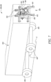
- FIG. 7 illustrates a perspective view of a weeding tool 100 according to another exemplary embodiment of the present invention.
- the weeding tool 100 is configured to maneuver or navigate on a plantation surface " G " on which the weed is grown.
- the weeding tool 100 is further configured to pick up weed from the plantation surface " G ".
- the weeding tool 100 as illustrated in FIG. 7 is a wheeled robot 600 configured to maneuver on the plantation surface " G ".
- the wheeled robot 600 includes a body 602 that further includes a pair of axles to support four wheels 604.
- the four wheels 604 are configured to maneuver the wheeled robot 600 on the plantation surface " G ".
- the body 602 includes an electronic housing on the inside of the body 602 such that the electronic housing houses the control unit to control the working of the weeding tool 100 or the wheeled robot 600.
- the navigation device is communicably coupled with the control unit such that the navigation device is configured to navigate the weeding tool 100 or the wheeled robot 600 on the plantation surface " G " to detect weeds on the plantation surface " G ".
- the wheeled robot 600 is mechanically coupled to the weed removal device 400.
- the weed removal device 400 is the clamp that includes the at least two arms 402 , 404 that are movable towards and away from each other to close and open the clamp respectively.
- the weed removal device 400 is mechanically coupled to the body 602 of the wheeled robot 600 via the slide and transmission frame 500 which is directly coupled to the body 602 of the wheeled robot 600.
- the slide and transmission frame 500 includes two elongate parts 502 slidably linked onto the body 602 such that the two elongate parts 502 allows reciprocating movement of the weed removal device 400 in the vertical direction perpendicular to the plantation surface " G ". Further, the two elongate parts 502 at least partially house the transmission box 504 that further mechanically couples to the weed removal device 400.
- the transmission box 504 houses the actuating device 310 and the secondary actuating device 320.
- the actuating device 310 is communicably coupled with the control unit.
- the actuating device 310 is an electric device, particularly the electric motor.
- the actuating device 310 is configured to actuate the movement in the weed removal device 400 towards and away from the plantation surface " G " when prompted or instructed by the control unit housed in the body 602.
- the actuating device 310 is configured to actuate the movement in the weed removal device 400 towards and away from the plantation surface " G " by sliding the two elongate parts 502 relative to the body 602 in the direction towards and away from the plantation surface " G ".
- the secondary actuating device 320 is operatively coupled to the control unit. In other words, the control unit controls the secondary actuating device 320 to move the at least two arms 402, 404 of the weed removal device 400 towards and away from each other to close and open the clamp respectively.
- the wheeled robot 600 maneuvers on the plantation surface " G " using the communication between the control unit and the navigation device communicably coupled with each other.
- the wheeled robot 600 based on the feedback of the navigation device reaches the location on the plantation surface " G " where the weed is grown.
- the weed removal device 400 is operatively coupled with the wheeled robot 600 such that the weed removal device 400 is movable towards and away from the plantation surface " G " when actuated by the actuating device 310.
- the control unit of the wheeled robot 600 is operatively coupled to the weed removal device 400 via the secondary actuating device 320 housed in the transmission box 504 such that the control unit operates to move the at least two arms 402, 404 away from each other, resulting in an angle between each other of 5 ° to 180 ° before instructing the actuating device 300 housed in the transmission box 504 to actuate the sliding movement of the two elongate parts 502 relative to the body 602 in the direction towards the plantation surface " G " and hence actuate the movement in the weed removal device 400 towards the plantation surface " G ".
- control unit actuates the movement in the weed removal device 400 towards the plantation surface " G " such that the at least two arms 402 , 404 of the weed removal device 400 touches the plantation surface " G " and surround the weed to be picked or grabbed.
- control unit housed in the body 602 of the wheeled robot 600 includes the sensing unit such that the sensing unit is configured to sense the touch of the weed removal device 400 or the at least two arms 402 , 404 of the weed removal device 400 with the plantation surface " G " on which the weed is grown by detecting the increase in electrical current drawn by the actuating device 310 when the weed removal device 400 is lowered towards the plantation surface " G ".
- the touching of the plantation surface " G " by the at least two arms 402 , 404 of the weed removal device 400 and further surrounding of the weed to be picked or grabbed by the at least two arms 402 , 404 is sensed by the sensing unit of the control unit by detecting the increase in electrical current drawn by the actuating device 300 as the at least two arms 402 , 404 face resistance from the plantation surface " G " and do not move further down.
- the weeding tool 100 or the wheeled robot 600 commences picking up of weed from the plantation surface " G " after the sensing unit senses the touch of the weed removal device 400 with the plantation surface " G " on which the weed is grown.
- the control unit of the wheeled robot 600 that is operatively coupled to the weed removal device 400 via the secondary actuating device 320 housed in the transmission box 504 operates to close the clamp (such that the at least two arms 402, 404 have the angle between each other of 0 °) and grab the weed to be picked before the control unit instructs the actuating device 310 to actuate the sliding of the two elongate parts 502 relative to the body 602 in the direction away from the plantation surface " G " and hence actuate the weed removal device 400 away from the plantation surface " G ".
- control unit instructs the actuating device 310 to actuate the sliding of the two elongate parts 502 relative to the body 602 in the direction away from the plantation surface " G " and hence actuate the weed removal device 400 away from the plantation surface " G " while still keeping the at least two arms 402 , 404 of the weed removal device 400 towards each other at 0 ° angle to keep the weed in a grabbed and uprooted state.
- the control unit of the wheeled robot 600 that is operatively coupled to the weed removal device 400 via the secondary actuating device 320 housed in the transmission box 504 operates to move the at least two arms 402 , 404 away from each other, resulting in an angle between each other of 5 ° to 180 ° after the weed removal device 400 is actuated away from the plantation surface " G ".
- the at least two arms 402 , 404 have the angle between each other of 5 ° to 180 °, the grabbed and uprooted weed is released for collection.
- FIG. 8 illustrates a perspective view of a weeding tool 100 according to yet another exemplary embodiment of the present invention.
- the weeding tool 100 is configured to maneuver or navigate on a plantation surface " G " on which the weed is grown.
- the weeding tool 100 is further configured to pick up weed from the plantation surface " G ".
- the weeding tool 100 as illustrated in FIG. 8 is the wheeled robot 600 configured to maneuver on the plantation surface " G ".
- the wheeled robot 600 includes a body 602 that further includes the pair of axles to support four wheels 604.
- the four wheels 604 are configured to maneuver the wheeled robot 600 on the plantation surface " G ".
- the body 602 includes an electronic housing on the inside of the body 602 such that the electronic housing houses the control unit to control the working of the wheeled robot 600.
- the navigation device is communicably coupled with the control unit such that the navigation device is configured to navigate the weeding tool 100 or the wheeled robot 600 on the plantation surface " G " to detect weeds on the plantation surface " G ".
- the wheeled robot 600 is mechanically coupled to the weed removal device 400 that includes the at least two arms 402 , 404 that are movable towards and away from each other to close and open the clamp respectively.
- the weed removal device 400 is mechanically coupled to the body 602 of the wheeled robot 600 via the slide and transmission frame 500 which is directly coupled to the body 602 of the wheeled robot 600.
- the slide and transmission frame 500 includes two elongate parts 502 slidably linked onto the body 602 such that the two elongate parts 502 allows reciprocating movement of the weed removal device 400 in the vertical direction perpendicular to the plantation surface " G ". Further, the two elongate parts 502 at least partially house the transmission box 504 that further mechanically couples to the weed removal device 400.
- the transmission box 504 houses the actuating device 300 and the secondary actuating device 320.
- the actuating device 310 is communicably coupled with the control unit.
- the actuating device 310 is particularly the electric motor.
- the actuating device 310 is configured to actuate the movement in the weed removal device 400 towards and away from the plantation surface " G " when prompted or instructed by the control unit housed in the body 602.
- the actuating device 310 is configured to actuate the movement in the weed removal device 400 towards and away from the plantation surface " G " by sliding the two elongate parts 502 relative to the body 602 in the direction towards and away from the plantation surface " G ".
- the secondary actuating device 320 is operatively coupled to the control unit. In other words, the control unit controls the secondary actuating device 320 to move the at least two arms 402, 404 of the weed removal device 400 towards and away from each other to close and open the clamp respectively.
- the weeding tool 100 or the wheeled robot 600 as illustrated in FIG. 8 additionally includes the video sensor and the image processing unit 700.
- the video sensor and the image processing unit 700 are separate from the navigation device.
- the video sensor and an image processing unit 700 is coupled to the bottom side of the body 602 of the wheeled robot 600 such that the video sensor and an image processing unit 700 is in close proximity with the weed removal tool 400 to visualize and process any movement in the weed removal tool 400.
- the weeding tool 100 or the wheeled robot 600 is communicably coupled with the video sensor and the image processing unit 700 via the control unit of the wheeled robot 600. In other words, the video sensor and the image processing unit 700 are communicably coupled with the control unit.
- the sensing unit of the control unit senses the touch of the weed removal device 400 with the plantation surface " G " by analyzing the data from the video sensor and the image processing unit 700.
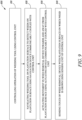
- FIG. 9 illustrates a flowchart of a method 800 of operating the weeding tool 100 for picking up weeds from the plantation surface " G ".
- the method 800 includes step 810.
- Step 810 includes controlling the operation of the weeding tool 100 using the control unit.
- Step 810 is followed by step 820.
- Step 820 includes navigating the weeding tool 100 on the plantation surface " G “ to detect weeds on the plantation surface " G “ using the navigation device communicably coupled with the control unit.
- step 830 includes actuating the movement in a weed removal device 400 towards and away from the plantation surface " G " using the actuating device 300 , 310 communicably coupled with the control unit.
- the weed removal device 400 is the clamp including at least two arms 402 , 404 movable towards and away from each other to close and open the clamp. Further step 830 is followed by step 840. Step 840 includes sensing the touch of the weed removal device 400 with the plantation surface " G " on which the weed is grown by using the sensing unit of the control unit.
- the sensing unit senses the touch of the weed removal device 400 with the plantation surface " G " by analyzing the data of the level sensor of the weeding tool 100 when the weed removal device 400 is lowered towards the plantation surface " G ".
- the level sensor is communicably coupled with the control unit.
- the sensing unit senses the touch of the weed removal device 400 with the plantation surface " G " by detecting the increase in electrical current drawn by the actuating device 310 when the weed removal device 400 is lowered towards the plantation surface " G ".
- the sensing unit senses the touch of the weed removal device 400 with the plantation surface " G " by analyzing the data from the video sensor and the image processing unit 700 provided with the weeding tool 100 such that the video sensor and the image processing unit 700 are communicably coupled with the control unit.
- the weeding tool 100 commences picking up of weed from the plantation surface " G " after the sensing unit senses the touch of the weed removal device 400 with the plantation surface " G “ on which the weed is grown.
- sensing the touch of the weed removal device 400 with the plantation surface “ G “ on which the weed is grown is the prerequisite for commencing picking up of weed from the plantation surface " G " by the weeding tool 100 or the walking robot 200.
Landscapes
- Life Sciences & Earth Sciences (AREA)
- Engineering & Computer Science (AREA)
- Mechanical Engineering (AREA)
- Soil Sciences (AREA)
- Environmental Sciences (AREA)
- Soil Working Implements (AREA)
Abstract
A weeding tool (100) for picking up weeds from a plantation surface (G) includes a control unit to control the working of the weeding tool (100). Further, a navigation device is communicably coupled with the control unit to navigate the weeding tool (100) on the plantation surface (G) to detect weeds on the plantation surface (G). Further, an actuating device (300, 310) is communicably coupled with the control unit such that the actuating device (300, 310) is an electric device configured to actuate a movement in the weed removal device (400) towards and away from the plantation surface (G) respectively. The weeding tool (100) is characterized in that the control unit includes a sensing unit configured to sense a touch of the weed removal device (400) with the plantation surface (G) on which the weed is grown. The weeding tool (100) commences picking up of weed from the plantation surface (G) after the sensing unit senses the touch of the weed removal device (400) with the plantation surface (G).
Description
- The present disclosure relates to a weeding tool for picking up weeds from a plantation surface.
- Devices for removing weeds are now common products in private gardening and vegetable growing. Robots that remove unwanted weeds are only known to a few. Large machine robots intended for agriculture have been developed at universities. Such robots either push the weeds deeper into the ground or have small plowshares installed therein, which bring the weeds to the surface by loosening them and then dry them up. A field robot is also known to burn the weeds with a laser beam. All field robots follow a strict lane and are not agile. Another well-known such product used as a little helper in the vegetable garden, for example, removes the upper part of the weeds with a rapidly rotating thread similar to a lawn trimmer. This product drives individually through the bed and removes everything that stands in the way. However, the plants themselves must be protected by means of an additional mowing protection to be attached. This is time-consuming and the mowing protection does not adapt to the variety of sizes of constantly growing plants.
- An example is provided by Chinese utility model
CN 217,256,336 U (hereinafter referred to as '336 reference). The '336 reference provides a weeding robot having a frame and a traveling mechanism arranged at the bottom of the frame. A solar power supply device is arranged at the top of the frame. A leveling mechanism is arranged at the upper part of the frame. An execution mechanism is arranged on the leveling mechanism, and an end effector is arranged at the tail end of the execution mechanism. The '336 reference provides a weeding robot having improved stability when facing complicated field terrain, realizes the accurate position of the weeds and automatically gets rid of the weeds in the crops. - Another example is provided by United States patent application
US 2023/0043631 A1 (hereinafter referred to as '631 reference). The '631 reference provides an apparatus for efficient targeting or removal of weeds or other plants. The apparatus may include a vehicle having a frame, a motor and a plurality of ground engaging members adapted to propel the vehicle over a surface. It may also include a robotic arm comprising a distal portion and a proximal portion coupled to the frame, and an implement, such as a tool or hoe connected to the distal portion of the robotic arm. The implement can be raised and lowered, and also moved relative to the surface by the robotic arm by pivoting or rotating the robotic arm at or near the proximal portion. - In view of the above, it is an objective of the present invention to solve or at least reduce the drawbacks discussed above. The objective is at least partially achieved by a weeding tool for picking up weeds from a plantation surface.
- According to an aspect of the present invention, a weeding tool for picking up weed from a plantation surface is provided. The weeding tool includes a control unit to control a working of the weeding tool. The weeding tool includes a navigation device communicably coupled with the control unit. The navigation device is configured to navigate the weeding tool on the plantation surface to detect weeds on the plantation surface. The weeding tool further includes an actuating device communicably coupled with the control unit. The actuating device is an electric device configured to actuate a movement in a weed removal device towards and away from the plantation surface. The weed removal device is a clamp comprising at least two arms movable towards and away from each other to close and open the clamp respectively. The weeding tool is characterized in that the control unit includes a sensing unit configured to sense a touch of the weed removal device with the plantation surface on which the weed is grown. The weeding tool commences picking up of weed from the plantation surface after the sensing unit senses the touch of the weed removal device with the plantation surface on which the weed is grown.
- Thus, the present disclosure provides an improved weeding tool that may provide a solution for completely automatic removal of weeds from a target area without any requirement of a manual intervention. The target area may be a garden area, a lawn, vegetable beds, ornamental beds, or any other similar application area. Weed removal is a tedious process for a user which consumes time, energy, and effort. The weeding tool may provide the user with a solution to automatedly remove weeds from a target area and may take care of this tedious process of weed removal without much additional input being required on each step. The weeding tool may autonomously identify the weed, navigate up to the weed, and destroy the weed therefrom. Thus, the weeding tool may improve the overall productivity of the user working in a particular target area. Various usage areas may be envisioned for the weeding tool as per requirements.
- According to an exemplary embodiment of the invention, the weeding tool is a walking robot with a front set of legs and a rear set of legs and configured to walk on the plantation surface. The front set of legs and the rear set of legs are configured to exhibit walking, lowering, and raising of the walking robot. The lowering and raising of the walking robot translates to the lowering and raising of the weed removal device towards and away from the plantation surface. The actuation device is configured to operate the front set of legs and the rear set of legs.
- The walking robot having a set of front legs and rear legs may allow for minimizing footprints of the weeding tool over the plantation surface. This may advantageously cause minimal intervention and therefore minimal damage to healthy plantation. The walking robot may walk up to the identified weed and lower and raise the weed removal device to remove the weed therefrom. Such movement may make it easier for the weeding tool to navigate around the plantation surface without causing any harm to the healthy plantation. In an possible embodiment the walking robot may have rollers/wheels at the end of the feet, thus to allow a rolling movement of the robot, in particular in a situation where the robot might change its orientation as far as the ground surface on which the robot walks allows for a rolling movement (such as turning around).
- According to an exemplary embodiment of the invention, the sensing unit senses the touch of the weed removal device with the plantation surface by analyzing a data of a level sensor of the walking robot when the weed removal device is lowered towards the plantation surface. The level sensor is communicably coupled with the control unit. Analysis of the data obtained from the level sensor may provide accurate estimation of inclination of the actuating device. Therefore, the control unit may accordingly sense the touch of the weed removal device with the plantation surface.
- According to an exemplary embodiment of the invention, the level sensor senses a differential angle of inclination of the walking robot. Based upon the inclination angle sensed, the control unit may accordingly control the actuating device to destroy the weed.
- According to an exemplary embodiment of the invention, the weeding tool is a wheeled robot configured to maneuver on the plantation surface. The weed removal device is operatively coupled with the wheeled robot. The weed removal device is movable towards and away from the plantation surface when actuated by the actuating device. The wheeled robot may provide easy maneuvering of the weeding tool on the plantation surface.
- According to an exemplary embodiment of the invention, the sensing unit senses the touch of the weed removal device with the plantation surface by detecting an increase in electrical current drawn by the actuating device when the weed removal device is lowered towards the plantation surface. Electrical current drawn by the actuating device may change with lowering and raising of the weed removal device with respect to the plantation surface. The sensing unit may detect the variation in the electric current and accordingly sense the touch of the weed removal device with the plantation surface.
- According to an exemplary embodiment of the invention, the actuation device is an electric motor. Electric motor may help to operate the weed removal device towards and away from the plantation surface.
- According to an exemplary embodiment of the invention, the weeding tool is communicably coupled with a video sensor and an image processing unit. The video sensor and the image processing unit in combination may help the control unit to sense the touch of the weed removal device with the plantation surface.
- According to an exemplary embodiment of the invention, the sensing unit senses the touch of the weed removal device with the plantation surface by analyzing a data from the video sensor and the image processing unit. The video sensor and the image processing unit are communicably coupled with the control unit. The video sensor may detect video signals of the plantation surface, and the image processing unit may process the video signals to determine the touch of the weed removal device with the plantation surface.
- According to an exemplary embodiment of the invention, the control unit is operatively coupled to the weed removal device such that the control unit operates to move at least two arms away from each other, resulting in an angle between each other of 5° to 180° before the actuating device actuates the movement in the weed removal device towards the plantation surface. The control unit may move the arms away so that the clamp is open to catch the weed.
- According to an exemplary embodiment of the invention, the control unit operates to move at least two arms of the weed removal device towards each other to close the clamp before the actuating device actuates the movement in the weed removal device away from the plantation surface. Closing the clamp may allow the weed removal device to catch and uproot the weed from the plantation surface.
- According to a further aspect of the present invention, a method of operating a weeding tool for picking up weeds from a plantation surface is provided. The method includes controlling the operation of the weeding tool using a control unit. The method includes navigating the weeding tool on the plantation surface to detect weeds on the plantation surface using a navigation device communicably coupled with the control unit. The method includes actuating a movement in a weed removal device towards and away from the plantation surface using an actuating device communicably coupled with the control unit. The weed removal device is a clamp comprising at least two arms movable towards and away from each other to close and open the clamp, respectively. The method is characterized in that sensing a touch of the weed removal device with the plantation surface on which the weed is grown is achieved by using a sensing unit of the control unit. The weeding tool commences picking up of weed from the plantation surface after the sensing unit senses the touch of the weed removal device with the plantation surface on which the weed is grown.
- The method of operating the weeding tool may provide a solution for completely automatic removal of weeds from a target area without any requirement of a manual intervention. The target area may be a garden area, a lawn, vegetable beds, ornamental beds, or any other similar application area. Weed removal is a tedious process for a user which consumes time, energy, and effort. The method of operating the weeding tool may provide the user with a solution to automatedly remove weeds from a target area and takes care of this tedious process of weed removal without much additional input being required on each step. The weeding tool may autonomously identify the weed, navigate up to the weed, and destroy the weed therefrom. Thus, the method may improve the overall productivity of the user working in a particular target area. Various usage areas may be envisioned for the weeding tool as per requirements.
- According to an exemplary embodiment of the invention, the method to operate the weeding tool includes that the sensing unit senses the touch of the weed removal device with the plantation surface by analyzing a data of a level sensor of the weeding tool when the weed removal device is lowered towards the plantation surface. The level sensor is communicably coupled with the control unit. Analysis of the data obtained from the level sensor may provide accurate estimation of inclination of the actuating device. Therefore, the control unit may accordingly sense the touch of the weed removal device with the plantation surface.
- According to an exemplary embodiment of the invention, the method to operate the weeding tool includes that the sensing unit senses the touch of the weed removal device with the plantation surface by detecting an increase in electrical current drawn by the actuating device when the weed removal device is lowered towards the plantation surface. Electrical current drawn by the actuating device may change with lowering and raising of the weed removal device with respect to the plantation surface. The sensing unit may detect the variation in the electric current and accordingly sense the touch of the weed removal device with the plantation surface.
- According to an exemplary embodiment of the invention, the method to operate the weeding tool includes that the sensing unit senses the touch of the weed removal device with the plantation surface by analyzing a data from a video sensor and an image processing unit. The video sensor and the image processing unit are communicably coupled with the control unit. The video sensor may detect video signals of the plantation surface, and the image processing unit may process the video signals to determine the touch of the weed removal device with the plantation surface.
- Before discussing the invention with the help of the drawings the invention will be briefly discussed in general. A walking robot, for example, with 4 -6 legs, similar to an ant in terms of sense of movement may be provided such that the walking robot may move at different speeds. The walking robot may lower its frame by bending the legs of the walking robot. The walking robot may be equipped with two arms. The weed detection may be done via camera detection comparison in the software. The walking robot may detect a boundary of a plantation surface. The floor level of the plantation surface may be scanned with the two arms slightly open. With this method, there may be a greater chance of easily grabbing the root of the weed in the plantation surface, and thus closer to the root. The walking robot may use two arms to scan the floor level of the plantation surface in several ways. One of the ways may be by lowering the two arms.
- The lowering of the two arms may be done by linear movement in a vertical direction. Feedback may be received by increasing the torque of an actuator of the linear motion. The walking robot may detect the weed (hereinafter referred to as a plant). The walking robot may position itself horizontally above the plant. The walking robot may position itself vertically above the plant. The two arms may set an opening angle greater than 5° and less than 180°. The two arms may move vertically down to the plantation surface. The motor torque of the two arms vertical adjustment may increase, and the software may process the data. The two arms may close and hold the plant in place. The two arms may move vertically and pull the plant out of the plantation surface. The two arms may open, and the plant may remain on the plantation surface.
- Another way may be by lowering the frame. The frame may be lowered by identical movement of all legs. Feedback may be received by position sensor of the overall control. The walking robot may detect the weed (hereinafter referred to as the plant). The walking robot may position itself horizontally above the plant. The walking robot may position itself vertically above the plant. The two arms may set an opening angle greater than 5° and less than 180°. The two arms may move vertically down to the plantation surface. The two arms may stand up and the walking robot may continue to move vertically. This may result in a differential angle of inclination, detected by means of a position sensor. The two arms may close and hold the plant in place. The walking robot may move vertically and may pull the plant out of the plantation surface. The two arms may open, and the plant may remain on the plantation surface.
- The walking robot according to the present invention may provide fully automatic removal of weeds in the plantation surface. Possible uses may be such as, but not limited to, in vegetable beds, in ornamental beds, in lawns etc.
- According to an exemplary embodiment of the invention, the walking robot may provide one or more means for detection of weeds, logical possibilities for detecting a floor height, and mechanics for removing the weed.
- Other features and aspects of this invention will be apparent from the following description and the accompanying drawings.
- The invention will be described in more detail with reference to the enclosed drawings, wherein:
-
FIG. 1 illustrates a perspective view of a weeding tool in accordance with an exemplary embodiment of the present disclosure; -
FIG. 2 illustrates a perspective view of a weed removal device with two arms of the weed removal device at an angle relative to each other in accordance with an exemplary embodiment of the present disclosure; -
FIG. 3 illustrates a perspective view of a weed removal device touching a plantation surface in accordance with an exemplary embodiment of the present disclosure; -
FIG. 4 illustrates a perspective view of a weed removal device with two arms of the weed removal device engaging each other in accordance with an exemplary embodiment of the present disclosure; -
FIG. 5 illustrates a perspective view of a weed removal device with two arms of the weed removal device uprooting a weed in accordance with an exemplary embodiment of the present disclosure; -
FIG. 6 illustrates another perspective view of a weed removal device with two arms of the weed removal device at an angle relative to each other in accordance with an exemplary embodiment of the present disclosure; -
FIG. 7 illustrates a perspective view of a wheeled robot in accordance with an exemplary embodiment of the present disclosure; -
FIG. 8 illustrates a perspective view of a wheeled robot having a video sensor and image processing unit in accordance with an exemplary embodiment of the present disclosure; and -
FIG. 9 illustrates a flowchart of a method of operating a weeding tool for picking up weeds from a plantation surface in accordance with an exemplary embodiment of the present disclosure. - The present invention will be described more fully hereinafter with reference to the accompanying drawings, in which example embodiments of the invention incorporating one or more aspects of the present invention are shown. This invention may, however, be embodied in many different forms and should not be construed as limited to the embodiments set forth herein; rather, these embodiments are provided so that this disclosure will be thorough and complete, and will fully convey the scope of the invention to those skilled in the art. For example, one or more aspects of the present invention may be utilized in other embodiments and even other types of structures and/or methods. In the drawings, like numbers refer to like elements.
- Certain terminology is used herein for convenience only and is not to be taken as a limitation on the invention. For example, "upper", "lower", "front", "rear", "side", "longitudinal", "lateral", "transverse", "upwards", "downwards", "forward", "backward", "sideward", "left," "right," "horizontal," "vertical," "upward", "inner", "outer", "inward", "outward", "top", "bottom", "higher", "above", "below", "central", "middle", "intermediate", "between", "end", "adjacent", "proximate", "near", "distal", "remote", "radial", "circumferential", or the like, merely describe the configuration shown in the Figures. Indeed, the components may be oriented in any direction and the terminology, therefore, should be understood as encompassing such variations unless specified otherwise.
-
FIG. 1 illustrates a perspective view of a weeding tool 100. The weeding tool 100 is configured to maneuver or navigate on a plantation surface "G" on which the weed is grown. The weeding tool 100 is further configured to pick up weed from the plantation surface "G". The weeding tool 100 as illustrated inFIG. 1 is a walking robot 200 configured to walk on the plantation surface "G". The walking robot 200 includes aframe 202. Theframe 202 houses electronics to control the operation of the walking robot 200. Theframe 202 houses a control unit to control the working of the weeding tool 100 or the walking robot 200. Theframe 202 additionally includes a video sensor and animage processing unit 700 coupled to the bottom side of theframe 202 of the walking robot 200. The video sensor and theimage processing unit 700 are communicably coupled with the control unit. Further, a navigation device is communicably coupled with the control unit such that the navigation device is configured to navigate the weeding tool 100 or the walking robot 200 on the plantation surface "G" to detect weeds on the plantation surface "G". The navigation device is separate from the video sensor and theimage processing unit 700. - The walking robot 200 further includes a front set of
legs 204 and a rear set oflegs 206 such that the front set oflegs 204 and the rear set oflegs 206 are configured to exhibit walking, lowering, and raising of the walking robot 200. The front set oflegs 204 includes twolegs 208 disposed at the front of the walking robot 200 and the rear set oflegs 206 includes twolegs 210 disposed at the rear of the walking robot 200. Further, each of the twolegs 208 of the front set oflegs 204 includes anupper leg portion 208A and alower leg portion 208B such that theupper leg portion 208A and thelower leg portion 208B are mechanically coupled to each other and movable relative to each other. Theupper leg portion 208A of each of the twolegs 208 of the front set oflegs 204 is mechanically coupled to theframe 202 while thelower leg portion 208B of each of the twolegs 208 of the front set oflegs 204 is configured to engage and disengage with the plantation surface "G". - Similarly, each of the two
legs 210 of the rear set oflegs 206 includes an upper leg portion 210A and alower leg portion 210B such that the upper leg portion 210A and thelower leg portion 210B are mechanically coupled to each other and movable relative to each other. The upper leg portion 210A of each of the twolegs 210 of the rear set oflegs 206 is mechanically coupled to theframe 202 while thelower leg portion 210B of each of the twolegs 210 of the rear set oflegs 206 is configured to engage and disengage with the plantation surface "G". Further, thelower leg portions legs 204 and the rear set oflegs 206 respectively are each provided with afoot 212 for soft landing on the plantation surface "G". - Further, during movement or walking phase of the walking robot 200, at any moment a pair of diagonally
opposite legs legs 204 and the rear set oflegs 206 are engaged with or grounded on the plantation surface "G" while other pair of diagonallyopposite legs legs 204 and the rear set oflegs 206 are disengaged from the plantation surface "G" or are in the air. - Further, the movement of the front set of
legs 204 and the rear set oflegs 206 is controlled by anactuating device 300, preferably fouractuating devices 300, as illustrated inFIG. 1 . In other words, theactuating device 300, preferably fouractuating devices 300 are configured to operate the front set oflegs 204 and the rear set oflegs 206. The fouractuating devices 300 are each assigned to the twolegs 208 of the front set oflegs 204 and the twolegs 210 of the rear set oflegs 206. The fouractuating devices 300 are electric devices respectively and are each communicably coupled to the control unit housed in theframe 202 of the walking robot 200 such that the control unit based on the feedback from the navigation device operates the fouractuating devices 300 such that the walking robot 200 maneuvers on the plantation surface "G" and reaches a location on the plantation surface "G" where the weed is grown. - Further, when the walking robot 200 reaches the location on the plantation surface "G" where the weed is grown, the two
legs 208 of the front set oflegs 204 as well as the twolegs 210 of the rear set oflegs 206 are all soft-landed on the plantation surface "G" such that the control unit communicably coupled with therespective actuating devices 300 of the twolegs 208 of the front set oflegs 204 as well as the twolegs 210 of the rear set oflegs 206 instructs theactuating devices 300 such that the twolegs 210, particularly the twoupper leg portions 208A and the twolegs 210, particularly the two upper leg portions 210A starts to lower towards the plantation surface "G". - With continuous reference to
FIG. 1 , theframe 202 of the walking robot 200 is mechanically coupled to aweed removal device 400 such that the lowering and raising of the walking robot 200 translates to the lowering and raising of theweed removal device 400 towards and away from the plantation surface "G". Theweed removal device 400 is a clamp that includes at least twoarms weed removal device 400 is mechanically coupled to theframe 202 of the walking robot 200 via a slide andtransmission frame 500 which is directly coupled to theframe 202 of the walking robot 200. - The slide and
transmission frame 500 includes twoelongate parts 502 slidably linked onto theframe 202 such that the twoelongate parts 502 optionally allows reciprocating movement of theweed removal device 400 in a vertical direction perpendicular to the plantation surface "G". Further, the twoelongate parts 502 at least partially house atransmission box 504 that further mechanically couples to theweed removal device 400. - The
transmission box 504 houses anactuating device 310 and asecondary actuating device 320 such that theactuating device 310 is communicably coupled to the control unit and thesecondary actuating device 320 is operatively coupled to the control unit. In other words, the control unit controls thesecondary actuating device 320 to move the at least twoarms weed removal device 400 towards and away from each other to close and open the clamp respectively. Further, theactuating device 310 optionally allows reciprocating movement of theweed removal device 400 towards and away from the plantation surface "G" by actuating the twoelongate parts 502 that are slidably linked onto theframe 202. Further, theactuating device 310 and thesecondary actuating device 320 are electric devices, particularly the electric motors respectively. - With continuous reference to
FIG. 1 , when theframe 202 lowers towards the plantation surface "G", due to the lowering of the twoupper leg portions 208A and the two upper leg portions 210A, the at least twoarms weed removal device 400 also lowers such that when the at least twoarms weed removal device 400 touches the plantation surface "G", the twoupper leg portions 208A of the front set oflegs 204 that are proximate to the at least twoarms arms weed removal device 400 continue to lower further within the feasible limits of lowering. Consequently, the walking robot 200 exhibits a substantially tilting orientation with a front of the walking robot 200 being at some inclination to a rear of the walking robot 200. This differential angle of inclination of the walking robot 200 is sensed by a level sensor communicably coupled with the control unit of the walking robot 200. The control unit includes a sensing unit such that the sensing unit is configured to sense the touch of theweed removal device 400 or the at least twoarms weed removal device 400 with the plantation surface "G" by analyzing a data of the level sensor of the walking robot 200 when theweed removal device 400 is lowered towards the plantation surface "G". - Optionally or additionally, and in particular if the lowering of the
frame 202 towards the plantation surface "G" is not desirous, then when the walking robot 200 reaches the location on the plantation surface "G" where the weed is grown, the control unit selectively instructs the actuating device 310 (instead of the four actuating devices 300) housed in thetransmission box 504 to actuate the movement in theweed removal device 400 towards and away from the plantation surface "G" by sliding the twoelongate parts 502 relative to theframe 202 in the direction towards and away from the plantation surface "G". Further, the sensing unit senses the touch of theweed removal device 400 or the at least twoarms weed removal device 400 with the plantation surface "G" on which the weed is grown by detecting an increase in electrical current drawn by theactuating device 310 when theweed removal device 400 is lowered towards the plantation surface "G". - Further optionally or additionally, the sensing unit (or in addition to detecting the increase in electrical current drawn by the actuating device 310) senses the touch of the
weed removal device 400 or the at least twoarms weed removal device 400 with the plantation surface "G" on which the weed is grown using the video sensor and theimage processing unit 700 coupled to the bottom side of theframe 202 of the walking robot 200. In other words, when theweed removal tool 400 or the at least twoarms weed removal device 400 lowers towards the plantation surface "G" on which the weed is grown and touch the plantation surface "G", the sensing unit of the control unit senses the touch of theweed removal device 400 with the plantation surface "G" by analyzing the data from the video sensor and theimage processing unit 700. - Also the walking robot depicted with
Fig. 1 shows and the according description elaborates on three different sensing units configured to sense a touch of the weed removal device (400) with the plantation surface (G) on which the weed is grown, it is obvious that just one or two of these sensing units are realized and embodied with the robot at one time. So for example the might not be anyimage processing unit 700 or the robot might just relay on theactuation device 310 being a motor of which the current drawn is analyzed. -
FIG. 2 illustrates a perspective view of the slide andtransmission frame 500 and theweed removal device 400. The control unit of the walking robot 200 is operatively coupled to theweed removal device 400 via thesecondary actuating device 320 housed in thetransmission box 504 such that the control unit operates to move the at least twoarms actuating device 300, preferably the fouractuating devices 300 to actuate the lowering movement in theframe 202 of the walking robot 200 and hence theweed removal device 400 towards the plantation surface "G", or instructing theactuating device 310 housed in thetransmission box 504 to actuate the movement in theweed removal device 400 towards and away from the plantation surface "G" by sliding the twoelongate parts 502 relative to theframe 202 in the direction towards and away from the plantation surface "G". -
FIG. 3 illustrates another perspective view of the slide andtransmission frame 500 and theweed removal device 400 with the at least twoarms actuating devices actuating devices 300, preferably the fouractuating devices 300 or instructs theactuating device 310 to lower theweed removal device 400 such that theweed removal device 400 or the at least twoarms weed removal device 400 touches the plantation surface "G". - When the control unit instructs the
actuating device 300, preferably the fouractuating devices 300 to lower theweed removal device 400 towards the plantation surface "G", the fouractuating devices 300 operate such that the twolegs 210, particularly the twoupper leg portions 208A and the twolegs 210, particularly the two upper leg portions 210A starts to lower towards the plantation surface "G" such that when the at least twoarms weed removal device 400 touches the plantation surface "G" and surround the weed to be picked or grabbed, the twoupper leg portions 208A of the front set oflegs 204 that are proximate to the at least twoarms arms weed removal device 400 continue to lower further within the feasible limits of lowering. - Consequently, the walking robot 200 exhibits the substantially tilting orientation with the front of the walking robot 200 being at some inclination to the rear of the walking robot 200. This differential angle of inclination of the walking robot 200 is sensed by the level sensor communicably coupled with the control unit of the walking robot 200. Further, the control unit includes the sensing unit such that the sensing unit is configured to sense the touch of the
weed removal device 400 or the at least twoarms weed removal device 400 with the plantation surface "G" by analyzing the data of the level sensor of the walking robot 200 when theweed removal device 400 is lowered towards the plantation surface "G" on which the weed is grown. - Further, when the control unit instructs the
actuating device 310 to lower theweed removal device 400 towards the plantation surface "G", theactuating device 310 operates to slide the twoelongate parts 502 relative to theframe 202 in the direction towards the plantation surface "G". Further, the sensing unit senses the touch of theweed removal device 400 or the at least twoarms weed removal device 400 with the plantation surface "G" on which the weed is grown by detecting the increase in electrical current drawn by theactuating device 310 when theweed removal device 400 is lowered towards the plantation surface "G". - Further, the sensing unit optionally (or in addition to detecting the increase in electrical current drawn by the actuating device 310) also senses the touch of the
weed removal device 400 or the at least twoarms weed removal device 400 with the plantation surface "G" on which the weed is grown using the video sensor and theimage processing unit 700 coupled to the bottom side of theframe 202 of the walking robot 200. -
FIG. 4 illustrates another perspective view of the slide andtransmission frame 500 and theweed removal device 400 with the at least twoarms weed removal device 400 with the plantation surface "G" on which the weed is grown. In other words, sensing the touch of theweed removal device 400 with the plantation surface "G" on which the weed is grown is a prerequisite for commencing picking up of weed from the plantation surface "G" by the weeding tool 100 or the walking robot 200. - The control unit of the walking robot 200 is operatively coupled to the
weed removal device 400 via thesecondary actuating device 320 housed in thetransmission box 504 such that the control unit operates to move the at least twoarms weed removal device 400 towards each other to close the clamp and grab the weed to be picked before the control unit selectively instructs either theactuating device 300, preferably the fouractuating devices 300, or theactuating device 310 to actuate the movement in theframe 202 by raising the twoupper leg portions 208A and the two upper leg portions 210A and hence actuate theweed removal device 400 away from the plantation surface "G", or to actuate the movement in theweed removal device 400 away from the plantation surface "G" by sliding the twoelongate parts 502 relative to theframe 202 in the direction away from the plantation surface "G" respectively. -
FIG. 5 illustrates another perspective view of the slide andtransmission frame 500 and theweed removal device 400 such that the control unit of the walking robot 200 either instructs theactuating device 300, preferably the fouractuating devices 300 to actuate the movement in theframe 202 by raising the twoupper leg portions 208A and the two upper leg portions 210A and hence actuate theweed removal device 400 away from the plantation surface "G" while still keeping the at least twoarms weed removal device 400 towards each other at 0° angle to keep the weed in a grabbed and uprooted state, or the control unit of the walking robot 200 instructs theactuating device 310 to actuate the movement in theweed removal device 400 away from the plantation surface "G" by sliding the twoelongate parts 502 relative to theframe 202 in the direction away from the plantation surface "G" while still keeping the at least twoarms weed removal device 400 towards each other at 0° angle to keep the weed in a grabbed and uprooted state. -
FIG. 6 illustrates yet another perspective view of the slide andtransmission frame 500 and theweed removal device 400 such that the control unit of the walking robot 200 is operatively coupled to theweed removal device 400 via thesecondary actuating device 320 housed in thetransmission box 504 such that the control unit operates to move the at least twoarms weed removal device 400 is actuated away from the plantation surface "G". When the at least twoarms -
FIG. 7 illustrates a perspective view of a weeding tool 100 according to another exemplary embodiment of the present invention. The weeding tool 100 is configured to maneuver or navigate on a plantation surface "G" on which the weed is grown. The weeding tool 100 is further configured to pick up weed from the plantation surface "G". The weeding tool 100 as illustrated inFIG. 7 is a wheeled robot 600 configured to maneuver on the plantation surface "G". The wheeled robot 600 includes abody 602 that further includes a pair of axles to support fourwheels 604. The fourwheels 604 are configured to maneuver the wheeled robot 600 on the plantation surface "G". - Further, the
body 602 includes an electronic housing on the inside of thebody 602 such that the electronic housing houses the control unit to control the working of the weeding tool 100 or the wheeled robot 600. Further, the navigation device is communicably coupled with the control unit such that the navigation device is configured to navigate the weeding tool 100 or the wheeled robot 600 on the plantation surface "G" to detect weeds on the plantation surface "G". - The wheeled robot 600 is mechanically coupled to the
weed removal device 400. Theweed removal device 400 is the clamp that includes the at least twoarms weed removal device 400 is mechanically coupled to thebody 602 of the wheeled robot 600 via the slide andtransmission frame 500 which is directly coupled to thebody 602 of the wheeled robot 600. - The slide and
transmission frame 500 includes twoelongate parts 502 slidably linked onto thebody 602 such that the twoelongate parts 502 allows reciprocating movement of theweed removal device 400 in the vertical direction perpendicular to the plantation surface "G". Further, the twoelongate parts 502 at least partially house thetransmission box 504 that further mechanically couples to theweed removal device 400. Thetransmission box 504 houses theactuating device 310 and thesecondary actuating device 320. - The
actuating device 310 is communicably coupled with the control unit. Theactuating device 310 is an electric device, particularly the electric motor. Theactuating device 310 is configured to actuate the movement in theweed removal device 400 towards and away from the plantation surface "G" when prompted or instructed by the control unit housed in thebody 602. Theactuating device 310 is configured to actuate the movement in theweed removal device 400 towards and away from the plantation surface "G" by sliding the twoelongate parts 502 relative to thebody 602 in the direction towards and away from the plantation surface "G". Further, thesecondary actuating device 320 is operatively coupled to the control unit. In other words, the control unit controls thesecondary actuating device 320 to move the at least twoarms weed removal device 400 towards and away from each other to close and open the clamp respectively. - During operation of the wheeled robot 600, the wheeled robot 600 maneuvers on the plantation surface "G" using the communication between the control unit and the navigation device communicably coupled with each other. The wheeled robot 600 based on the feedback of the navigation device reaches the location on the plantation surface "G" where the weed is grown.
- Further, the
weed removal device 400 is operatively coupled with the wheeled robot 600 such that theweed removal device 400 is movable towards and away from the plantation surface "G" when actuated by theactuating device 310. In other words, the control unit of the wheeled robot 600 is operatively coupled to theweed removal device 400 via thesecondary actuating device 320 housed in thetransmission box 504 such that the control unit operates to move the at least twoarms actuating device 300 housed in thetransmission box 504 to actuate the sliding movement of the twoelongate parts 502 relative to thebody 602 in the direction towards the plantation surface "G" and hence actuate the movement in theweed removal device 400 towards the plantation surface "G". - Further, the control unit actuates the movement in the
weed removal device 400 towards the plantation surface "G" such that the at least twoarms weed removal device 400 touches the plantation surface "G" and surround the weed to be picked or grabbed. Further, the control unit housed in thebody 602 of the wheeled robot 600 includes the sensing unit such that the sensing unit is configured to sense the touch of theweed removal device 400 or the at least twoarms weed removal device 400 with the plantation surface "G" on which the weed is grown by detecting the increase in electrical current drawn by theactuating device 310 when theweed removal device 400 is lowered towards the plantation surface "G". In other words, the touching of the plantation surface "G" by the at least twoarms weed removal device 400 and further surrounding of the weed to be picked or grabbed by the at least twoarms actuating device 300 as the at least twoarms - Further, the weeding tool 100 or the wheeled robot 600 commences picking up of weed from the plantation surface "G" after the sensing unit senses the touch of the
weed removal device 400 with the plantation surface "G" on which the weed is grown. In other words, upon detection of the touch of the plantation surface "G" by the at least twoarms weed removal device 400, the control unit of the wheeled robot 600 that is operatively coupled to theweed removal device 400 via thesecondary actuating device 320 housed in thetransmission box 504 operates to close the clamp (such that the at least twoarms actuating device 310 to actuate the sliding of the twoelongate parts 502 relative to thebody 602 in the direction away from the plantation surface "G" and hence actuate theweed removal device 400 away from the plantation surface "G". - Further, the control unit instructs the
actuating device 310 to actuate the sliding of the twoelongate parts 502 relative to thebody 602 in the direction away from the plantation surface "G" and hence actuate theweed removal device 400 away from the plantation surface "G" while still keeping the at least twoarms weed removal device 400 towards each other at 0° angle to keep the weed in a grabbed and uprooted state. - Further, when the
weed removal device 400 is away from the plantation surface "G", the control unit of the wheeled robot 600 that is operatively coupled to theweed removal device 400 via thesecondary actuating device 320 housed in thetransmission box 504 operates to move the at least twoarms weed removal device 400 is actuated away from the plantation surface "G". When the at least twoarms -
FIG. 8 illustrates a perspective view of a weeding tool 100 according to yet another exemplary embodiment of the present invention. The weeding tool 100 is configured to maneuver or navigate on a plantation surface "G" on which the weed is grown. The weeding tool 100 is further configured to pick up weed from the plantation surface "G". The weeding tool 100 as illustrated inFIG. 8 is the wheeled robot 600 configured to maneuver on the plantation surface "G". The wheeled robot 600 includes abody 602 that further includes the pair of axles to support fourwheels 604. The fourwheels 604 are configured to maneuver the wheeled robot 600 on the plantation surface "G". - Further, the
body 602 includes an electronic housing on the inside of thebody 602 such that the electronic housing houses the control unit to control the working of the wheeled robot 600. Further, the navigation device is communicably coupled with the control unit such that the navigation device is configured to navigate the weeding tool 100 or the wheeled robot 600 on the plantation surface "G" to detect weeds on the plantation surface "G". - The wheeled robot 600 is mechanically coupled to the
weed removal device 400 that includes the at least twoarms weed removal device 400 is mechanically coupled to thebody 602 of the wheeled robot 600 via the slide andtransmission frame 500 which is directly coupled to thebody 602 of the wheeled robot 600. - The slide and
transmission frame 500 includes twoelongate parts 502 slidably linked onto thebody 602 such that the twoelongate parts 502 allows reciprocating movement of theweed removal device 400 in the vertical direction perpendicular to the plantation surface "G". Further, the twoelongate parts 502 at least partially house thetransmission box 504 that further mechanically couples to theweed removal device 400. Thetransmission box 504 houses theactuating device 300 and thesecondary actuating device 320. - The
actuating device 310 is communicably coupled with the control unit. Theactuating device 310 is particularly the electric motor. Theactuating device 310 is configured to actuate the movement in theweed removal device 400 towards and away from the plantation surface "G" when prompted or instructed by the control unit housed in thebody 602. Theactuating device 310 is configured to actuate the movement in theweed removal device 400 towards and away from the plantation surface "G" by sliding the twoelongate parts 502 relative to thebody 602 in the direction towards and away from the plantation surface "G". Further, thesecondary actuating device 320 is operatively coupled to the control unit. In other words, the control unit controls thesecondary actuating device 320 to move the at least twoarms weed removal device 400 towards and away from each other to close and open the clamp respectively. - The weeding tool 100 or the wheeled robot 600 as illustrated in
FIG. 8 additionally includes the video sensor and theimage processing unit 700. The video sensor and theimage processing unit 700 are separate from the navigation device. The video sensor and animage processing unit 700 is coupled to the bottom side of thebody 602 of the wheeled robot 600 such that the video sensor and animage processing unit 700 is in close proximity with theweed removal tool 400 to visualize and process any movement in theweed removal tool 400. The weeding tool 100 or the wheeled robot 600 is communicably coupled with the video sensor and theimage processing unit 700 via the control unit of the wheeled robot 600. In other words, the video sensor and theimage processing unit 700 are communicably coupled with the control unit. - When the
weed removal tool 400 or the at least twoarms weed removal device 400 lowers towards the plantation surface "G" on which the weed is grown and touch the plantation surface "G", the sensing unit of the control unit senses the touch of theweed removal device 400 with the plantation surface "G" by analyzing the data from the video sensor and theimage processing unit 700. -
FIG. 9 illustrates a flowchart of amethod 800 of operating the weeding tool 100 for picking up weeds from the plantation surface "G". Themethod 800 includesstep 810. Step 810 includes controlling the operation of the weeding tool 100 using the control unit. Step 810 is followed bystep 820. Step 820 includes navigating the weeding tool 100 on the plantation surface "G" to detect weeds on the plantation surface "G" using the navigation device communicably coupled with the control unit.Further step 820 is followed bystep 830 that includes actuating the movement in aweed removal device 400 towards and away from the plantation surface "G" using theactuating device weed removal device 400 is the clamp including at least twoarms Further step 830 is followed bystep 840. Step 840 includes sensing the touch of theweed removal device 400 with the plantation surface "G" on which the weed is grown by using the sensing unit of the control unit. - In one exemplary embodiment of the present invention, the sensing unit senses the touch of the
weed removal device 400 with the plantation surface "G" by analyzing the data of the level sensor of the weeding tool 100 when theweed removal device 400 is lowered towards the plantation surface "G". The level sensor is communicably coupled with the control unit. - In another exemplary embodiment of the present invention, the sensing unit senses the touch of the
weed removal device 400 with the plantation surface "G" by detecting the increase in electrical current drawn by theactuating device 310 when theweed removal device 400 is lowered towards the plantation surface "G". - In yet another exemplary embodiment of the present invention, the sensing unit senses the touch of the
weed removal device 400 with the plantation surface "G" by analyzing the data from the video sensor and theimage processing unit 700 provided with the weeding tool 100 such that the video sensor and theimage processing unit 700 are communicably coupled with the control unit. - Further, the weeding tool 100 commences picking up of weed from the plantation surface "G" after the sensing unit senses the touch of the
weed removal device 400 with the plantation surface "G" on which the weed is grown. In other words, sensing the touch of theweed removal device 400 with the plantation surface "G" on which the weed is grown is the prerequisite for commencing picking up of weed from the plantation surface "G" by the weeding tool 100 or the walking robot 200. - In the drawings and specification, there have been disclosed exemplary embodiments and examples of the invention and, although specific terms are employed, they are used in a generic and descriptive sense only and not for the purpose of limitation of the scope of the invention being set forth in the following claims.
-
- 100
- Weeding Tool
- 200
- Walking Robot
- 202
- Frame
- 204
- Front set of Legs
- 206
- Rear Set of Legs
- 208
- Legs
- 208A
- Upper Leg Portion
- 208B
- Lower Leg Portion
- 210
- Legs
- 210A
- Upper Leg Portion
- 210B
- Lower Leg Portion
- 212
- Foot
- 300
- Actuating Device
- 310
- Actuating Device
- 320
- Secondary Actuating Device
- 400
- Weed Removal Device
- 402
- Arm
- 404
- Arm
- 500
- Slide and Transmission Frame
- 502
- Elongate Parts
- 504
- Transmission Box
- 600
- Wheeled Robot
- 602
- Body
- 604
- Wheels
- 700
- Video Sensor and Image Processing Unit
- 800
- Method
- 810
- Step
- 820
- Step
- 830
- Step
- 840
- Step
- G
- Ground Surface
Claims (15)
- A weeding tool (100) for picking up weed from a plantation surface (G), comprising:a control unit to control a working of the weeding tool (100),a navigation device communicably coupled with the control unit, wherein the navigation device is configured to navigate the weeding tool (100) on the plantation surface (G) to detect weeds on the plantation surface (G),an actuating device (300, 310) communicably coupled with the control unit, wherein the actuating device (300, 310) is an electric device configured to actuate a movement in a weed removal device (400) towards and away from the plantation surface (G),wherein the weed removal device (400) being a clamp comprising at least two arms (402, 404) movable towards and away from each other to close and open the clamp respectively,characterized in that:the control unit comprises a sensing unit configured to sense a touch of the weed removal device (400) with the plantation surface (G) on which the weed is grown,wherein the weeding tool (100) commences picking up of weed from the plantation surface (G) after the sensing unit senses the touch of the weed removal device (400) with the plantation surface (G) on which the weed is grown.
- The weeding tool (100) for picking up weeds from the plantation surface (G) according to claim 1,wherein the weeding tool (100) is a walking robot (200) with a front set of legs (204) and a rear set of legs (206) and configured to walk on the plantation surface (G),wherein the front set of legs (204) and the rear set of legs (206) are configured to exhibit walking, lowering, and raising of the walking robot (200),wherein the lowering and raising of the walking robot (200) translates to the lowering and raising of the weed removal device (400) towards and away from the plantation surface (G), andwherein the actuation device (300) is configured to operate the front set of legs (204) and the rear set of legs (206).
- The weeding tool (100) for picking up weeds from the plantation surface (G) according to claim 2,wherein the sensing unit senses the touch of the weed removal device (400) with the plantation surface (G) by analyzing a data of a level sensor of the walking robot (200) when the weed removal device (400) is lowered towards the plantation surface (G),wherein the level sensor is communicably coupled with the control unit.
- The weeding tool (100) for picking up weeds from the plantation surface (G) according to claim 3,
wherein the level sensor senses a differential angle of inclination of the walking robot (200). - The weeding tool (100) for picking up weeds from the plantation surface (G) according to claim 1,wherein the weeding tool (100) is a wheeled robot (600) configured to maneuver on the plantation surface (G),wherein the weed removal device (400) is operatively coupled with the wheeled robot (600),wherein the weed removal device (400) is movable towards and away from the plantation surface (G) when actuated by the actuating device (310).
- The weeding tool (100) for picking up weeds from the plantation surface (G) according to any one of the preceding claims,wherein the sensing unit senses the touch of the weed removal device (400) with the plantation surface (G) by detecting an increase in electrical current drawn by the actuating device (310) when the weed removal device (400) is lowered towards the plantation surface (G),wherein the weed removal device (400) is movable towards and away from the plantation surface (G) when actuated by the actuating device (310).
- The weeding tool (100) for picking up weeds from the plantation surface (G) according to claim 6,
wherein the actuation device (310) is an electric motor. - The weeding tool (100) for picking up weeds from the plantation surface (G) according to any one of the preceding claims,
wherein the weeding tool (100) is communicably coupled with a video sensor and an image processing unit (700). - The weeding tool (100) for picking up weeds from the plantation surface (G) according to claim 8,wherein the sensing unit senses the touch of the weed removal device (400) with the plantation surface (G) by analyzing a data from the video sensor and the image processing unit (700),wherein the video sensor and the image processing unit (700) are communicably coupled with the control unit.
- The weeding tool (100) for picking up weeds from the plantation surface (G) according to any one of the preceding claims,
wherein the control unit is operatively coupled to the weed removal device (400) such that the control unit operates to move at least two arms (402, 404) away from each other, resulting in an angle between each other of 5° to 180° before the actuating device (300, 310) actuates the movement in the weed removal device (400) towards the plantation surface (G). - The weeding tool (100) for picking up weeds from the plantation surface (G) according to claim 10,
wherein the control unit operates to move at least two arms (402, 404) of the weed removal device (400) towards each other to close the clamp before the actuating device (300, 310) actuates the movement in the weed removal device (400) away from the plantation surface (G). - A method (800) of operating a weeding tool (100) for picking up weeds from a plantation surface (G), comprising:controlling the operation of the weeding tool (100) using a control unit,navigating the weeding tool (100) on the plantation surface (G) to detect weeds on the plantation surface (G) using a navigation device communicably coupled with the control unit,actuating a movement in a weed removal device (400) towards and away from the plantation surface (G) using an actuating device (300, 310) communicably coupled with the control unit, wherein the weed removal device (400) being a clamp comprising at least two arms (402, 404) movable towards and away from each other to close and open the clamp respectively,characterized in that:sensing a touch of the weed removal device (400) with the plantation surface (G) on which the weed is grown by using a sensing unit of the control unit,wherein the weeding tool (100) commences picking up of weed from the plantation surface (G) after the sensing unit senses the touch of the weed removal device (400) with the plantation surface (G) on which the weed is grown.
- The method (800) of operating the weeding tool (100) for picking up weeds from the plantation surface (G) according to claim 12, wherein the sensing unit senses the touch of the weed removal device (400) with the plantation surface (G) by analyzing a data of a level sensor of the weeding tool (100) when the weed removal device (400) is lowered towards the plantation surface (G),
wherein the level sensor is communicably coupled with the control unit. - The method (800) of operating the weeding tool (100) for picking up weeds from the plantation surface (G) according to claim 12, wherein the sensing unit senses the touch of the weed removal device (400) with the plantation surface (G) by detecting an increase in electrical current drawn by the actuating device (310) when the weed removal device (400) is lowered towards the plantation surface (G).
- The method (800) of operating the weeding tool (100) for picking up weeds from the plantation surface (G) according to claim 12, wherein the sensing unit senses the touch of the weed removal device (400) with the plantation surface (G) by analyzing a data from a video sensor and an image processing unit (700),
wherein the video sensor and the image processing unit (700) are communicably coupled with the control unit.
Priority Applications (2)
| Application Number | Priority Date | Filing Date | Title |
|---|---|---|---|
| EP23207778.4A EP4548733A1 (en) | 2023-11-03 | 2023-11-03 | A weeding tool |
| PCT/EP2024/080033 WO2025093410A1 (en) | 2023-11-03 | 2024-10-24 | A weeding tool |
Applications Claiming Priority (1)
| Application Number | Priority Date | Filing Date | Title |
|---|---|---|---|
| EP23207778.4A EP4548733A1 (en) | 2023-11-03 | 2023-11-03 | A weeding tool |
Publications (1)
| Publication Number | Publication Date |
|---|---|
| EP4548733A1 true EP4548733A1 (en) | 2025-05-07 |
Family
ID=88697761
Family Applications (1)
| Application Number | Title | Priority Date | Filing Date |
|---|---|---|---|
| EP23207778.4A Withdrawn EP4548733A1 (en) | 2023-11-03 | 2023-11-03 | A weeding tool |
Country Status (2)
| Country | Link |
|---|---|
| EP (1) | EP4548733A1 (en) |
| WO (1) | WO2025093410A1 (en) |
Citations (6)
| Publication number | Priority date | Publication date | Assignee | Title |
|---|---|---|---|---|
| US6671582B1 (en) * | 2002-08-26 | 2003-12-30 | Brian P. Hanley | Flexible agricultural automation |
| CN108135122A (en) * | 2015-06-05 | 2018-06-08 | 悉尼大学 | Automatic target detection and management system |
| JP6976088B2 (en) * | 2017-06-27 | 2021-12-01 | 株式会社クボタ | Travel route setting system and aerial work platform |
| US11246256B2 (en) * | 2020-02-09 | 2022-02-15 | Stout Industrial Technology, Inc. | Machine vision control system for precision agriculture |
| CN217256336U (en) | 2022-04-21 | 2022-08-23 | 西北农林科技大学 | Weeding robot |
| US20230043631A1 (en) | 2021-08-04 | 2023-02-09 | Greentech Robotics Limited | Agricultural Weed Removal System |
-
2023
- 2023-11-03 EP EP23207778.4A patent/EP4548733A1/en not_active Withdrawn
-
2024
- 2024-10-24 WO PCT/EP2024/080033 patent/WO2025093410A1/en active Pending
Patent Citations (6)
| Publication number | Priority date | Publication date | Assignee | Title |
|---|---|---|---|---|
| US6671582B1 (en) * | 2002-08-26 | 2003-12-30 | Brian P. Hanley | Flexible agricultural automation |
| CN108135122A (en) * | 2015-06-05 | 2018-06-08 | 悉尼大学 | Automatic target detection and management system |
| JP6976088B2 (en) * | 2017-06-27 | 2021-12-01 | 株式会社クボタ | Travel route setting system and aerial work platform |
| US11246256B2 (en) * | 2020-02-09 | 2022-02-15 | Stout Industrial Technology, Inc. | Machine vision control system for precision agriculture |
| US20230043631A1 (en) | 2021-08-04 | 2023-02-09 | Greentech Robotics Limited | Agricultural Weed Removal System |
| CN217256336U (en) | 2022-04-21 | 2022-08-23 | 西北农林科技大学 | Weeding robot |
Also Published As
| Publication number | Publication date |
|---|---|
| WO2025093410A1 (en) | 2025-05-08 |
Similar Documents
| Publication | Publication Date | Title |
|---|---|---|
| US11490563B2 (en) | Weeding robot and method | |
| US11337354B2 (en) | Automatic target recognition and management system | |
| CN109952857B (en) | Orchard mower capable of automatically completing mowing operation and method | |
| Scarfe et al. | Development of an autonomous kiwifruit picking robot | |
| KR102001517B1 (en) | agricultural mobile robot for unmanned automation of agricultural production | |
| JP6925070B2 (en) | Working device with a tubular rotating body | |
| JP3131993B2 (en) | Visual devices such as fruit and vegetable harvesters | |
| KR102566841B1 (en) | Furrow weed removal robot | |
| WO2010063075A1 (en) | Crop picking device and method | |
| KR101817072B1 (en) | Flying drone for agricultural management and operating method of it | |
| JP4013351B2 (en) | Fruit harvesting robot | |
| CA2212375A1 (en) | A system for harvesting crop items and crop harvesting tools used therewith | |
| KR20210137864A (en) | Agricultural mowing system with obstacle avoidance function | |
| EP4524675A2 (en) | A mobile autonomous agricultural system | |
| JP2020048585A (en) | Work vehicle | |
| KR102298784B1 (en) | Artificial intelligence variable complex tillage robot for weed management of upland crop | |
| WO2020161528A1 (en) | Machine for agricultural use | |
| WO2025093410A1 (en) | A weeding tool | |
| KR20230174457A (en) | Weed removal apparatus for weed removal robot | |
| US12552477B2 (en) | Electric vehicle with moveable operator's chair | |
| JP2615426B2 (en) | Harvesting work vehicle | |
| RU2854871C1 (en) | Method for removing weeds | |
| Garg et al. | Revolutionizing Cotton Harvesting: Advancements and Implications | |
| KR20250125194A (en) | Weed loading structure for weed removal robot | |
| CN115868322B (en) | A plant protection robot |
Legal Events
| Date | Code | Title | Description |
|---|---|---|---|
| PUAI | Public reference made under article 153(3) epc to a published international application that has entered the european phase |
Free format text: ORIGINAL CODE: 0009012 |
|
| STAA | Information on the status of an ep patent application or granted ep patent |
Free format text: STATUS: THE APPLICATION HAS BEEN PUBLISHED |
|
| AK | Designated contracting states |
Kind code of ref document: A1 Designated state(s): AL AT BE BG CH CY CZ DE DK EE ES FI FR GB GR HR HU IE IS IT LI LT LU LV MC ME MK MT NL NO PL PT RO RS SE SI SK SM TR |
|
| STAA | Information on the status of an ep patent application or granted ep patent |
Free format text: STATUS: THE APPLICATION IS DEEMED TO BE WITHDRAWN |
|
| 18D | Application deemed to be withdrawn |
Effective date: 20251108 |