EP4546612A1 - Procédé d obtention d'un rotor pour machine électrique tournante - Google Patents
Procédé d obtention d'un rotor pour machine électrique tournante Download PDFInfo
- Publication number
- EP4546612A1 EP4546612A1 EP24207885.5A EP24207885A EP4546612A1 EP 4546612 A1 EP4546612 A1 EP 4546612A1 EP 24207885 A EP24207885 A EP 24207885A EP 4546612 A1 EP4546612 A1 EP 4546612A1
- Authority
- EP
- European Patent Office
- Prior art keywords
- rotor
- hoop
- bonded magnet
- rotor body
- notches
- Prior art date
- Legal status (The legal status is an assumption and is not a legal conclusion. Google has not performed a legal analysis and makes no representation as to the accuracy of the status listed.)
- Pending
Links
Images


Classifications
-
- H—ELECTRICITY
- H02—GENERATION; CONVERSION OR DISTRIBUTION OF ELECTRIC POWER
- H02K—DYNAMO-ELECTRIC MACHINES
- H02K1/00—Details of the magnetic circuit
- H02K1/06—Details of the magnetic circuit characterised by the shape, form or construction
- H02K1/22—Rotating parts of the magnetic circuit
- H02K1/27—Rotor cores with permanent magnets
- H02K1/2706—Inner rotors
- H02K1/272—Inner rotors the magnetisation axis of the magnets being perpendicular to the rotor axis
- H02K1/274—Inner rotors the magnetisation axis of the magnets being perpendicular to the rotor axis the rotor consisting of two or more circumferentially positioned magnets
- H02K1/2753—Inner rotors the magnetisation axis of the magnets being perpendicular to the rotor axis the rotor consisting of two or more circumferentially positioned magnets the rotor consisting of magnets or groups of magnets arranged with alternating polarity
- H02K1/276—Magnets embedded in the magnetic core, e.g. interior permanent magnets [IPM]
-
- H—ELECTRICITY
- H02—GENERATION; CONVERSION OR DISTRIBUTION OF ELECTRIC POWER
- H02K—DYNAMO-ELECTRIC MACHINES
- H02K1/00—Details of the magnetic circuit
- H02K1/06—Details of the magnetic circuit characterised by the shape, form or construction
- H02K1/22—Rotating parts of the magnetic circuit
- H02K1/27—Rotor cores with permanent magnets
- H02K1/2706—Inner rotors
- H02K1/272—Inner rotors the magnetisation axis of the magnets being perpendicular to the rotor axis
- H02K1/2726—Inner rotors the magnetisation axis of the magnets being perpendicular to the rotor axis the rotor consisting of a single magnet or two or more axially juxtaposed single magnets
- H02K1/2733—Annular magnets
-
- H—ELECTRICITY
- H02—GENERATION; CONVERSION OR DISTRIBUTION OF ELECTRIC POWER
- H02K—DYNAMO-ELECTRIC MACHINES
- H02K1/00—Details of the magnetic circuit
- H02K1/06—Details of the magnetic circuit characterised by the shape, form or construction
- H02K1/22—Rotating parts of the magnetic circuit
- H02K1/28—Means for mounting or fastening rotating magnetic parts on to, or to, the rotor structures
-
- H—ELECTRICITY
- H02—GENERATION; CONVERSION OR DISTRIBUTION OF ELECTRIC POWER
- H02K—DYNAMO-ELECTRIC MACHINES
- H02K15/00—Processes or apparatus specially adapted for manufacturing, assembling, maintaining or repairing of dynamo-electric machines
- H02K15/02—Processes or apparatus specially adapted for manufacturing, assembling, maintaining or repairing of dynamo-electric machines of stator or rotor bodies
- H02K15/03—Processes or apparatus specially adapted for manufacturing, assembling, maintaining or repairing of dynamo-electric machines of stator or rotor bodies having permanent magnets
-
- H—ELECTRICITY
- H02—GENERATION; CONVERSION OR DISTRIBUTION OF ELECTRIC POWER
- H02K—DYNAMO-ELECTRIC MACHINES
- H02K15/00—Processes or apparatus specially adapted for manufacturing, assembling, maintaining or repairing of dynamo-electric machines
- H02K15/12—Impregnating, moulding insulation, heating or drying of windings, stators, rotors or machines
-
- H—ELECTRICITY
- H02—GENERATION; CONVERSION OR DISTRIBUTION OF ELECTRIC POWER
- H02K—DYNAMO-ELECTRIC MACHINES
- H02K2213/00—Specific aspects, not otherwise provided for and not covered by codes H02K2201/00 - H02K2211/00
- H02K2213/03—Machines characterised by numerical values, ranges, mathematical expressions or similar information
Definitions
- the present invention relates to the field of motor vehicles, and more particularly to the electrical machines equipping these motor vehicles.
- Electric or hybrid motor vehicles are equipped with rotating electrical machines, including electric motors with at least one stator and one rotor.
- rotating electrical machines including electric motors with at least one stator and one rotor.
- windings associated with the stator generate, when electrically powered, a magnetic flux that allows rotation of the rotor equipped with magnets.
- a radial flux rotating machine the magnetic flux is generated in a radial direction relative to an axis of rotation of the electric machine and the rotor rotates around this axis of rotation depending on the orientation of the radial magnetic field.
- the rotors of these rotating machines typically include a hoop and a magnetic element.
- This hoop ensures that the rotor's magnetic element is held in position, particularly by ensuring that it is held when the rotor is rotating at high speed.
- the hoop includes an inner radial wall, an outer radial wall, and a bottom wall that define housings open on the top to receive portions of the magnetic element. The magnetic element is thus arranged within the hoop, against a bottom thereof.
- the magnetic element is typically a solid magnet, which requires assembly operations to be secured to the hoop.
- both the arrangement of the magnetic element within the hoop and their attachment to each other are complex operations. It is indeed difficult to control the dimensional tolerances between these two components.
- manufacturing the rotor requires considerable time and investment, due to the multiplication of positioning and assembly operations.
- the present invention falls within this context by proposing a method of manufacturing a rotor thanks to which the production of the rotor is simplified, while reducing the number of operations required.
- the production method according to the invention corresponds to the manufacture of a rotor intended to be integrated into a rotating electrical machine and in particular into a radial flux rotating machine.
- the production method involves an injection mold having a cavity, within which a rotor body and a hoop are positioned in turn, respectively during a positioning step and a placement step. Either the rotor body positioning step occurs before the hoop placement step, or conversely the hoop placement step takes place prior to the rotor body positioning step.
- the rotor body is positioned as close as possible to a central pin of the injection mold while the hoop is placed along an external edge of this injection mold.
- the rotor body and the hoop are arranged so as not to be in contact with each other; in other words, at the end of the positioning and placement steps a space remains between these two components. Since the rotor body and the hoop are annular in shape, this space corresponds to an annular chamber.
- the production process comprises an injection step during which a magnetic element of the rotor, here a bonded magnet, is injected into the injection mold in the annular chamber between the rotor body and the hoop.
- the material constituting the bonded magnet then polymerizes to form, with the rotor body and the hoop, a set of secured components.
- injection allows the arrangement of the bonded magnet to be easily managed relative to those of the rotor body and the hoop. Indeed, the bonded magnet matches the shape of both the rotor body and the hoop. Injection also allows the bottom wall of the hoop to be dispensed with, the bonded magnet being retained by the injection mold during the production process. In addition, injection allows the combination of positioning and assembly operations that were previously dissociated during the production of prior art rotors.
- the rotor body comprises notches, a portion of the bonded magnet being inserted within the notches of the rotor body during the injection step.
- the rotor body notches are cutouts that extend at least radially from an edge of the rotor body that faces the hoop.
- the notches are annular in shape. They extend, depending on the embodiment, over an entire circumference of the rotor body or over a portion of this circumference. When the bonded magnet is injected into the injection mold, it fills these notches.
- the hoop comprises notches, a portion of the bonded magnet being inserted within the notches of the hoop during the injection step.
- the notches in the hoop are cutouts that extend at least radially from a face of the hoop that faces the rotor body.
- the notches are not continuous along this inner face of the hoop; thus, there are a plurality of notches arranged at a distance from each other on the same circumference of the hoop that are inscribed in the inner face of the hoop facing the rotor body. When the bonded magnet is injected into the injection mold, it fills these notches.
- the production method comprises a step of pre-magnetization of the magnet linked within the injection mold, this pre-magnetization step involving coils arranged in the injection mold around a zone for placement of the hoop.
- the coils are arranged equidistant from each other within the injection mold. Their orientation depends on the type of magnetization sought; thus, the coils will be straight, that is to say parallel to the axis of rotation of the rotor, for magnetization according to a Hallbach arrangement, or on the contrary they will be inclined relative to the axis of rotation of the rotor in the case of an inclined or twisted rotor.
- the purpose of the pre-magnetization step is to orient the magnetic charges of the bonded magnet formed from a polymer material in which particles or grains of magnetic material are embedded. These grains of magnetic material which participate in forming the bonded magnet are thus oriented according to field lines defined within the injection mold, which is in a magnetic field. When the polymer material constituting the bonded magnet polymerizes, the positions of its grains of magnetic material are fixed. The bonded magnet then has a fixed magnetic orientation.
- the production method comprises a step of magnetizing the bonded magnet outside the injection mold.
- the bonded magnet is remagnetized so as to give it a magnetic charge while respecting the previously defined orientations.
- the rotor body includes indexing means to facilitate magnetization based on angular sectors defined during pre-magnetization.
- pre-magnetization and magnetization operations may take place at separate locations.
- pre-magnetization may be performed at a supplier's location and magnetization at a customer's location, with the bonded magnet undergoing a demagnetization step between the pre-magnetization and magnetization steps to facilitate its transportation.
- the invention further relates to a rotor of a rotating electrical machine capable of being produced according to the production method as mentioned above, the rotor having an axis of rotation and comprising a rotor body and a hoop arranged around the rotor body so as to form an annular chamber, and a linked magnet arranged in said annular chamber.
- the rotor according to the invention is intended to be part of a rotating electrical machine, for example a radial flux motor, for installation in an electric or hybrid motor vehicle.
- the rotor body makes it possible to secure the linked magnet to a motor shaft element of the rotating electrical machine.
- the role of the hoop is to hold the linked magnet in position when the rotor rotates at high speed and to avoid a risk of bursting of the linked magnet.
- the rotor body, bonded magnet and hoop are arranged in this order around the rotor rotation axis, which is the result of the initial arrangement of the rotor body and hoop within the injection mold.
- the bonded magnet comprises tabs which extend in a plane perpendicular to the axis of rotation of the rotor within the rotor body and/or the hoop.
- the tabs of the bonded magnet extend radially within the rotor body and/or the hoop.
- the tabs of the bonded magnet extend within notches of the rotor body.
- the tabs of the bonded magnet extend within notches of the hoop.
- the hoop has an annular shape.
- the hoop according to the invention is, unlike the hoops of the prior art, devoid of a bottom.
- a bottom the function of which is to retain the bonded magnet, is in fact not necessary since the bonded magnet is injected.
- it is the injection mold which makes it possible to retain the bonded magnet.
- the hoop comprises at least one collar, preferably openwork, partially covering the bonded magnet.
- the collar corresponds to an excess thickness of the hoop which extends towards the axis of rotation of the rotor.
- the collar is discontinuous along a periphery of the hoop, which facilitates the feasibility of the method for obtaining the rotor. This discontinuity is intended to block the rotation of the hoop on the bonded magnet during operation of the machine. Alternatively, the collar extends around the entire periphery of the hoop.
- the bonded magnet has an axial end edge which helps to form an axial peripheral edge of the rotor.
- the axial end edge delimits the bonded magnet in a direction parallel to the axis of rotation of the rotor.
- the axial peripheral edge delimits the rotor in a direction parallel to this axis of rotation of the rotor. It is understood that the bonded magnet is at least partially cleared within the rotor. In other words, the bonded magnet is not completely covered by the hoop, this hoop being devoid of a bottom wall.
- the rotor body comprises a first portion intended to be in contact with a motor shaft element and a second portion in contact with the linked magnet, the rotor body comprising branches extending radially between the first portion and the second portion.
- the first portion and the second portion have annular shapes. They are connected to each other by the branches of the rotor body. In sectional view along a plane perpendicular to the axis of rotation of the rotor, the branches extend in a star shape from the first portion. The presence of branches connecting the first portion and the second portion rather than a solid body helps to limit the weight of the rotor body.
- the bonded magnet is made from an alloy of rare earths or ferrites and a non-magnetic bonding material.
- the rare earth alloy includes, for example, neodymium, iron, and boron.
- the non-magnetic material is, in particular, a resin such as a thermoplastic based on polyamide or polyphenylene sulfide.
- the invention further relates to a rotating electrical machine comprising a rotor as mentioned above and at least one stator.
- variants of the invention may be combined with each other in various combinations, provided that they are not incompatible or mutually exclusive.
- variants of the invention may be conceived comprising only a selection of features described below in isolation from the other features described, if this selection of features is sufficient to confer a technical advantage and/or to differentiate the invention from the prior art.
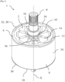
- THE figures 1 to 3 thus illustrate, schematically, a rotor 1 according to the invention.
- This rotor 1 is intended to be integrated within a rotating electrical machine, for example a radial flux electric motor further comprising at least one stator, in order to equip a hybrid or electric vehicle, for example a car, a truck, a bicycle or an object which moves with its traction system such as a drone.
- a vehicle may further comprise an autonomous driving system.
- the rotating electrical machine is capable of operating in an alternator mode to supply energy in particular to the battery and the on-board network of the vehicle, and in an engine mode, not only to ensure the starting of the thermal engine of the vehicle, but also to participate in the traction of the vehicle alone or in combination with the thermal engine.
- the power of the machine may be between 4kW and 50kW.
- the electric machine may be installed on an axle of the motor vehicle, in particular a rear axle.
- the electric machine advantageously has an operating voltage of less than 60 Volts, and preferably 48 Volts.
- the torque provided by the electric machine is between 30N.m and 150N.m.
- the electric machine may have an operating voltage of more than 60V, or even more than 80V or more than 100V, in particular 300V or more.
- the machine will typically have an operating voltage of between 400 and 800V, a power of up to 350kW and will provide a torque of up to 400N.m.
- the rotor 1 comprises a rotor body 2, a magnetic element in the form of a bonded magnet 4 and a hoop 6. These constituent elements of the rotor 1 are arranged in this order around an axis of rotation X of the rotor 1.
- the rotor body 2 is arranged around a motor shaft element 8 which is shown in Figure 1 .
- the rotor body 2 is a metallic element, for example made of steel.
- the rotor body 2 is composed of a first annular portion 10, a second annular portion 12 and branches 14 extending radially between the first portion 10 and the second portion 12.
- the first portion 10 surrounds the motor shaft element 8 while the second portion 12, of a larger diameter than the first portion 10, is arranged in contact with the linked magnet 4.
- the branches 14 extend in a star shape; it is understood that between these branches, the rotor body 1 is devoid of material.
- the branches 14 are arranged at regular intervals between the first portion 10 and the second portion 12.
- the rotor body 2 here comprises eight branches 14, but one could, without departing from the scope of the invention, envisage a rotor body 2 having a different number of branches 14.
- the branches 14 extend over an entire height of the rotor 1, such height being measured along the axis of rotation X of the rotor 1.
- the branches 14 extend from a first axial peripheral edge 16 of the rotor body 2 to a second axial peripheral edge 18 thereof, these axial peripheral edges 16, 18 being opposite in a direction parallel to the axis of rotation X of the rotor 1.
- the rotor body 2 has notches 20, visible on the Figure 2 , which are formed within its second portion 12.
- the notches 20 are more precisely formed within a contact face 22 of the second portion 12 of the rotor body 2 which is intended to be opposite the linked magnet 4 and in contact with the latter.
- the 20 notches which are particularly visible on the Figure 2 in which the rotor body 2 is shown in isolation, extend from the contact face 22 in the direction of the axis of rotation X of the rotor 1.
- the notches 20 do not pass right through the second portion 12.
- the notches 20 comprise first notches 20A which extend axially, i.e. parallel to the axis of rotation X of the rotor 1, as well as second notches 20B which extend radially around the second portion 12, i.e. along a circumference of the rotor body 2. It is understood that the first notches 20A and the second notches 20B are perpendicular to each other.
- the grid of notches 20 which is thus formed within the rotor body 2 allows optimal coverage, but one could envisage another arrangement of the notches 20 without departing from the scope of the invention.
- the rotor body 2 radially delimits the rotor 1 as close as possible to the axis of rotation X of the rotor 1 while the hoop 6 radially delimits the rotor 1 for its part furthest from this axis of rotation X.
- the rotor body 2 constitutes an internal radial end of the rotor 1 in the vicinity of the axis of rotation X and the hoop 6 constitutes an opposite external radial end of the rotor 1 at a distance from the axis of rotation X.
- the hoop 6 is a non-magnetic annular element which is for example made of stainless steel or carbon.
- the hoop 6 comprises an external face 24 oriented towards an exterior of the rotor 1 and an internal face 26, radially opposite the external face 24, facing the linked magnet 4 and the rotor body 2.
- the hoop 6 comprises notches 28 formed at least in its internal face 26. These notches 28 are here circumferentially separated from each other; in other words, they are not continuous along the hoop 6. As illustrated in Figure 3 , the notches 28 are through-cut, that is to say they extend from the internal face 26 of the hoop to its external face 24. In an alternative embodiment not shown here, the notches 28 could extend radially over an entire circumference of the internal face 26, it being understood that they would then not be through-cut, that is to say they would only extend partially into the thickness of the hoop.
- the second notches 20B and the notches 28 are arranged at different heights along a direction parallel to the axis of rotation X of the rotor 1.
- a given second notch 20B of the rotor body 2 is not arranged opposite a given notch 28 of the hoop 6.
- the hoop 6 has at least one collar 30.
- This collar 30 extends the annular body of the hoop 6 in the direction of the axis of rotation X of the rotor 1.
- the collar 30 is arranged along a periphery 32 of the hoop 6.
- This periphery 32 corresponds to a rim which delimits the hoop 6 relative to a direction parallel to the axis of rotation X of the rotor 1.
- the collar 30 is here openwork, that is to say that it extends partially along the periphery 32.
- the collar 30 is here divided into three portions distributed at regular intervals around the periphery 32.
- the collar 30 would be continuous along the periphery 32.
- the collar 30 partially covers the bonded magnet 4.
- the bonded magnet 4 has a generally annular shape. It extends radially between the contact face 22 of the second portion 12 of the rotor body 2 and the internal face 26 of the hoop 6 and it extends, along a direction parallel to the axis of rotation X of the rotor 1, between a first axial end edge 34 and a second axial end edge 36. Between the first axial end edge 34 and the second axial end edge 36, the bonded magnet 4 comprises a central zone 38.
- One of the collars 30 is more particularly in covering a portion of the first axial end edge 34 and the other of the collars 30 is covering a portion of the second axial end edge 36. It is therefore understood that at the level of the collar 30, the linked magnet 4 has a height, measured along a direction parallel to the axis of rotation X of the rotor 1, less than a height of the linked magnet 4 measured in the vicinity of the rotor body 2.
- a radial dimension of the first axial end edge 34 of the linked magnet 4 and/or a dimension of the second axial end edge 36, measured in a plane perpendicular to the axis of rotation X of the rotor 1 opposite the collar 30, is less than a dimension of the central zone 38 measured in this perpendicular plane.
- the collar 30 only partially covers the bonded magnet 4. As a result, the bonded magnet 4 is uncovered, at least partially, within the rotor 1.
- the first axial end edge 34 of the bonded magnet 4 forms the first axial peripheral edge 14 of the rotor 1 and the second axial end edge 36 of the bonded magnet 4 forms the second axial peripheral edge 16 of the rotor 1.
- the bonded magnet 4 has tabs 40.
- the tabs 40 correspond to a point increase in a radial dimension of the bonded magnet 4 measured in a plane perpendicular to the axis of rotation X of the rotor 1. These tabs 40 extend radially from the central zone 38 of the bonded magnet 4, both in the direction of the rotor body 2 and the hoop 6.
- the tabs 40 are more precisely positioned within the notches 20 of the rotor body 2 and the notches 28 of the hoop 6. Such positioning of the tabs 40 results from the injection of the bonded magnet 4 into an annular chamber between the rotor body 2 and the hoop 6 during a production process which will now be detailed.
- the method for obtaining the rotor 1 according to the invention results in the manufacture of a rotor 1 as described above.
- the method of obtaining requires the use of an injection mold 42 in the general shape of a rounded base cylinder.
- the injection mold 42 comprises an annular cavity which is delimited radially by a central pin 46 and by an annular rim 48.
- the cavity is delimited axially by a bottom wall 50 and by a cover 44.
- Windings 52 are arranged around the cavity, for example within the annular rim 48 as can be seen in Figure 3 .
- the production process begins with steps of manufacturing the rotor body 2 and the hoop 6.
- the rotor body 2 is for example made of steel, while the hoop 6 is made of stainless steel.
- Each of the rotor body 2 and the hoop 6 are manufactured so as to have their respective notches 20 and slots 28.
- the method of obtaining comprises a step of positioning the rotor body 2 within the injection mold 42.
- the rotor body 2 is more precisely arranged against the bottom wall 50 and around the central pin 46 of the injection mold 42, the diameter of which is substantially identical to that of the drive shaft element 8 mentioned previously.
- the first portion 10 of the rotor body 2 is in contact with the central pin 46.
- the hoop 6 is in turn arranged within the cavity of the injection mold 42, in contact with its bottom wall 50 and its annular rim 48. More precisely, the external face 24 of the hoop 6 is placed in contact with the annular rim 48.
- the method continues with a closing step during which the injection mold 42 is closed by the cover 44, which delimits a radial end of the rotor 1.
- the cover 44 rests on the rotor body 2 and on the hoop 6. It is understood from the above that the rotor body 2 and the hoop 6 are arranged at a radial distance from each other within the injection mold 42, so as to form an annular chamber between them.
- the bonded magnet 4 is injected into this annular chamber between the rotor body 2 and the hoop 6.
- the material composing the bonded magnet 4 here an alloy of rare earths and a non-magnetic polymer material, is thus injected into the injection mold 42 using injection nozzles 54.
- the material composing the bonded magnet 4 is deposited against the bottom wall 50 of the cavity of the injection mold 42. It fills the annular chamber as well as the notches 20 of the rotor body 2 and the notches 28 of the hoop 6.
- the material composing the bonded magnet 4 is injected into the cavity of the injection mold 42 up to the level of the first axial peripheral edge 16 of the rotor 1, and opposite the collar 30 up to the periphery 32 of the hoop 6.
- the production method comprises a pre-magnetization step during which the windings 52 arranged within the annular rim 48 are electrically powered to orient magnetic charges of the bonded magnet 4.
- the magnetic charges of the bonded magnet 4 are fixed, that is to say once the material composing the polymerized bonded magnet 4, the rotor body 2, the bonded magnet 4 and the hoop 6 form a single-piece assembly.
- the rotor 1 thus formed can then be removed from the injection mold 42 and demagnetized for transport.
- the obtaining method then comprises a step of assembling the rotor 1 to the motor shaft element 8, during which this motor shaft element 8 is inserted within the first portion 10 of the rotor body 2.
- the obtaining method can continue with a magnetization step which makes it possible to give the linked magnet 4 a magnetic charge according to the orientations determined during the previous pre-magnetization step.
- the magnetization step is facilitated by the presence of indexing means, here holes 56, which give an operator manufacturing the rotor 1 information concerning the orientation to be respected according to what was defined during the pre-magnetization step.
- the rotor 1 can then be associated with a stator in order to form a rotating electrical machine.
- the present invention thus proposes a method for obtaining a rotor that is simplified in terms of the number of operations, the management of dimensional tolerances between a magnetic element and other components of the rotor being further facilitated.
Landscapes
- Engineering & Computer Science (AREA)
- Power Engineering (AREA)
- Manufacturing & Machinery (AREA)
- Permanent Field Magnets Of Synchronous Machinery (AREA)
- Manufacture Of Motors, Generators (AREA)
Abstract
La présente invention concerne un procédé d'obtention d'un rotor (1) d'une machine électrique tournante comprenant un corps de rotor (2), un élément magnétique et une frette (6), le procédé d'obtention comprenant une étape de positionnement du corps de rotor (2) au sein d'un moule d'injection (42) et une étape de placement de la frette (6) au sein du moule d'injection (42), de sorte que la frette (6) soit placée autour du corps de rotor (2), ainsi qu'une étape d'injection de l'élément magnétique, sous forme d'aimant lié (4), entre le corps de rotor (2) et la frette (6).
Description
- La présente invention concerne le domaine des véhicules automobiles, et plus particulièrement les machines électriques équipant ces véhicules automobiles.
- Les véhicules automobiles électriques ou hybrides sont équipés de machines électriques tournantes, notamment des moteurs électriques avec au moins un stator et un rotor. Dans certaines de ces machines tournantes, des bobinages associés au stator génèrent, lorsqu'ils sont alimentés électriquement, un flux magnétique qui permet une rotation du rotor équipé d'aimants. Dans une machine tournante à flux radial, le flux magnétique est généré selon une direction radiale par rapport à un axe de rotation de la machine électrique et le rotor tourne autour de cet axe de rotation en fonction de l'orientation du champ magnétique radial.
- Les rotors de ces machines tournantes comportent classiquement une frette et un élément magnétique. Cette frette permet d'assurer un maintien en position de l'élément magnétique du rotor, notamment en assurant sa tenue lorsque le rotor tourne à grande vitesse. La frette comporte une paroi radiale interne, une paroi radiale externe et une paroi de fond qui délimitent des logements ouverts sur le dessus pour recevoir des portions de l'élément magnétique. L'élément magnétique est de la sorte disposé au sein de la frette, contre un fond de celle-ci.
- L'élément magnétique est classiquement un aimant solide, qui nécessite des opérations d'assemblage pour être solidarisé à la frette. Cependant, tant la disposition de l'élément magnétique au sein de la frette que leur solidarisation l'un à l'autre sont des opérations complexes. Il est en effet difficile de maîtriser les tolérances dimensionnelles entre ces deux composants. Par ailleurs, la fabrication du rotor nécessite un temps et un investissement considérables, du fait de la multiplication des opérations de positionnement et d'assemblage.
- La présente invention s'inscrit dans ce contexte en proposant un procédé de fabrication d'un rotor grâce auquel la réalisation du rotor est simplifiée, tout réduisant le nombre des opérations nécessaires.
- La présente invention a ainsi pour principal objet un procédé d'obtention d'un rotor d'une machine électrique tournante comprenant un corps de rotor, un élément magnétique et une frette, le procédé d'obtention comprenant les étapes suivantes :
- positionnement du corps de rotor au sein d'un moule d'injection ;
- placement de la frette autour du corps de rotor de manière à former une chambre annulaire,
- injection de l'élément magnétique, sous forme d'aimant lié, dans la chambre annulaire.
- Le procédé d'obtention selon l'invention correspond à la fabrication d'un rotor destiné à être intégré dans une machine électrique tournante et notamment dans une machine tournante à flux radial. Le procédé d'obtention fait intervenir un moule d'injection présentant une cavité, au sein de laquelle sont tour à tour positionnés un corps de rotor et une frette, respectivement au cours d'une étape de positionnement et d'une étape de placement. Soit l'étape de positionnement du corps de rotor survient avant l'étape de placement de la frette, soit à l'inverse l'étape de placement de la frette a lieu préalablement à l'étape de positionnement du corps de rotor. Le corps de rotor est positionné au plus proche d'un pion central du moule d'injection tandis que la frette est placée le long d'un bord externe de ce moule d'injection. Le corps de rotor et la frette sont disposés de sorte à ne pas être au contact l'un de l'autre ; en d'autres termes, à l'issue des étapes de positionnement et de placement un espace subsiste entre ces deux composants. Le corps de rotor et la frette étant de forme annulaire, cet espace correspond à une chambre annulaire.
- Une fois le corps de rotor et la frette disposés dans le moule, le procédé d'obtention comprend une étape d'injection au cours de laquelle un élément magnétique du rotor, ici un aimant lié, est injecté au sein du moule d'injection dans la chambre annulaire entre le corps de rotor et la frette. Le matériau constituant l'aimant lié polymérise ensuite pour former, avec le corps de rotor et la frette, un ensemble de composants solidarisés.
- Le recours à l'injection permet de gérer facilement la disposition de l'aimant lié relativement à celles du corps de rotor et de la frette. En effet, l'aimant lié épouse à la fois la forme du corps de rotor et celle de la frette. L'injection permet également de s'affranchir de la paroi de fond de la frette, l'aimant lié étant au cours du procédé d'obtention retenu par le moule d'injection. En outre, l'injection permet de combiner des opérations de positionnement et d'assemblage qui étaient auparavant dissociées lors de la réalisation des rotors de l'art antérieur.
- Selon une caractéristique optionnelle de l'invention, le corps de rotor comprend des entailles, une partie de l'aimant lié étant insérée au sein des entailles du corps de rotor au cours de l'étape d'injection.
- Les entailles du corps de rotor sont des découpes qui s'étendent au moins radialement à partir d'un bord du corps de rotor qui est en regard de la frette. Les entailles sont de forme annulaire. Elles s'étendent, selon les modes de réalisation, sur tout un pourtour du corps de rotor ou sur une portion de ce pourtour. Lorsque l'aimant lié est injecté dans le moule d'injection, il remplit ces entailles.
- Selon une caractéristique optionnelle de l'invention, la frette comprend des encoches, une partie de l'aimant lié étant insérée au sein des encoches de la frette au cours de l'étape d'injection.
- Les encoches de la frette sont des découpes qui s'étendent au moins radialement à partir d'une face de la frette qui est en regard du corps de rotor. Les encoches ne sont pas continues le long de cette face interne de la frette ; ainsi, il y a une pluralité d'encoches disposées à distance les unes des autres sur une même circonférence de la frette s'inscrivant dans la face interne de la frette en regard du corps de rotor. Lorsque l'aimant lié est injecté dans le moule d'injection, il remplit ces encoches.
- Selon une caractéristique optionnelle de l'invention, le procédé d'obtention comprend une étape de pré-magnétisation de l'aimant lié au sein du moule d'injection, cette étape de pré-magnétisation faisant intervenir des bobinages disposés dans le moule d'injection autour d'une zone de placement de la frette.
- Les bobinages sont disposés à équidistance les uns des autres au sein du moule d'injection. Leur orientation dépend du type de magnétisation recherché ; ainsi, les bobinages seront droits, c'est-à-dire parallèles à l'axe de rotation du rotor, pour une magnétisation selon un arrangement de Hallbach, ou au contraire elles seront inclinées par rapport à l'axe de rotation du rotor dans le cadre d'un rotor incliné ou vrillé. L'étape de pré-magnétisation a pour but d'orienter les charges magnétiques de l'aimant lié formé d'une matière polymère dans laquelle sont noyés des particules ou grains de matière magnétique. Ces grains de matière magnétique qui participent à former l'aimant lié s'orientent ainsi selon des lignes de champs définies au sein du moule d'injection, qui est dans un champ magnétique. Lorsque la matière polymère constituant l'aimant lié polymérise, les positions de ses grains de matière magnétique se figent. L'aimant lié présente alors une orientation magnétique figée.
- Selon une caractéristique optionnelle de l'invention, le procédé d'obtention comprend une étape de magnétisation de l'aimant lié en dehors du moule d'injection.
- L'aimant lié est remagnétisé de sorte à lui redonner une charge magnétique en respectant les orientations préalablement définies. À cet effet, le corps de rotor comprend des moyens d'indexage permettant de faciliter la magnétisation en fonction de secteurs angulaires définis lors de la pré-magnétisation.
- Les opérations de pré-magnétisation et de magnétisation peuvent avoir lieu en des endroits distincts. À titre d'exemple, la pré-magnétisation peut être réalisée chez fournisseur et la magnétisation chez un client, l'aimant lié subissant alors une étape de démagnétisation entre l'étape de pré-magnétisation et l'étape de magnétisation afin de faciliter son transport.
- L'invention concerne par ailleurs un rotor d'une machine électrique tournante susceptible d'être réalisé selon le procédé d'obtention tel qu'évoqué précédemment, le rotor présentant un axe de rotation et comprenant un corps de rotor et une frette disposée autour du corps de rotor de manière à former une chambre annulaire, et un aimant lié disposé dans ladite chambre annulaire.
- Le rotor selon l'invention est destiné à faire partie d'une machine électrique tournante, par exemple un moteur à flux radial, en vue de son installation au sein d'un véhicule automobile électrique ou hybride. Le corps de rotor permet de solidariser l'aimant lié à un élément d'arbre moteur de la machine électrique tournante. La frette a pour rôle de maintenir en position l'aimant lié lorsque le rotor tourne à grande vitesse et d'éviter un risque d'éclatement de l'aimant lié.
- Le corps de rotor, l'aimant lié et la frette sont disposés dans cet ordre autour de l'axe de rotation du rotor, ce qui est le résultat de la disposition initiale du corps de rotor et de la frette au sein du moule d'injection.
- Selon une caractéristique optionnelle de l'invention, l'aimant lié comprend des languettes qui s'étendent dans un plan perpendiculaire à l'axe de rotation du rotor au sein du corps de rotor et/ou de la frette.
- En d'autres termes, les languettes de l'aimant lié s'étendent radialement au sein du corps de rotor et/ou de la frette.
- Selon une caractéristique optionnelle de l'invention, les languettes de l'aimant lié s'étendent au sein d'entailles du corps de rotor.
- Selon une caractéristique optionnelle de l'invention, les languettes de l'aimant lié s'étendent au sein d'encoches de la frette.
- La présence d'une portion de l'aimant lié, à savoir ses languettes, au sein des entailles du corps de rotor et/ou des encoches de la frette permet de limiter des glissements entre les différents éléments du rotor au cours du fonctionnement de la machine électrique tournante.
- Selon une caractéristique optionnelle de l'invention, la frette présente une forme annulaire.
- Notamment, la frette selon l'invention est contrairement aux frettes de l'art antérieur dépourvue de fond. Un tel fond, dont la fonction est de retenir l'aimant lié, n'est en effet pas nécessaire puisque l'aimant lié est injecté. En outre, lors du procédé d'obtention c'est le moule d'injection qui permet de retenir l'aimant lié.
- Selon une caractéristique optionnelle de l'invention, la frette comprend au moins une collerette, de préférence ajourée, en recouvrement partiel de l'aimant lié.
- La collerette correspond à une surépaisseur de la frette qui s'étend en direction de l'axe de rotation du rotor.
- Dans certains modes de réalisation, la collerette est discontinue le long d'un pourtour de la frette, ce qui facilite la faisabilité du procédé d'obtention du rotor. Cette discontinuité a pour but de bloquer la rotation de la frette sur l'aimant lié lors du fonctionnement de la machine. Alternativement, la collerette s'étend sur tout le pourtour de la frette.
- Selon une caractéristique optionnelle de l'invention, l'aimant lié présente un bord d'extrémité axial qui participe à former un bord périphérique axial du rotor.
- Le bord d'extrémité axial délimite l'aimant lié selon une direction parallèle à l'axe de rotation du rotor. Le bord périphérique axial délimite le rotor selon une direction parallèle à cet axe de rotation du rotor. On comprend que l'aimant lié est au moins partiellement dégagé au sein du rotor. En d'autres termes, l'aimant lié n'est pas intégralement recouvert par la frette, cette frette étant dépourvue de paroi de fond.
- Selon une caractéristique optionnelle de l'invention, le corps de rotor comprend une première portion destinée à être au contact d'un élément d'arbre moteur et une deuxième portion au contact de l'aimant lié, le corps de rotor comprenant des branches s'étendant radialement entre la première portion et la deuxième portion.
- La première portion et la deuxième portion présentent des formes annulaires. Elles sont reliées l'une à l'autre par les branches du corps de rotor. En vue de coupe selon un plan perpendiculaire à l'axe de rotation du rotor, les branches s'étendent en étoile à partir de la première portion. La présence de branches reliant la première portion et la deuxième portion plutôt qu'un corps plein permet de limiter le poids du corps de rotor.
- Selon une caractéristique optionnelle de l'invention, l'aimant lié est réalisé à partir d'un alliage de terres rares ou ferrites et d'un matériau liant amagnétique.
- L'alliage de terres rares comprend par exemple du néodyme, du fer et du bore. Le matériau amagnétique est notamment une résine telle qu'un thermoplastique à base de polyamide ou de sulfure de polyphénylène.
- L'invention concerne en outre une machine électrique tournante comprenant un rotor tel qu'évoqué précédemment et au moins un stator.
- D'autres caractéristiques, détails et avantages de l'invention ressortiront plus clairement à la lecture de la description qui suit d'une part, et d'exemples de réalisation donnés à titre indicatif et non limitatif en référence aux dessins annexés d'autre part, sur lesquels :
- [
Fig. 1 ] illustre, schématiquement, un rotor d'une machine électrique tournante selon l'invention, comprenant un corps de rotor, une frette et un aimant lié ayant été injecté entre le corps de rotor et la frette. - [
Fig. 2 ] illustre, schématiquement et de façon isolée, le corps de rotor de lafigure 1 ; - [
Fig. 3 ] illustre, schématiquement, un moule d'injection au sein duquel sont disposés le corps de rotor, la frette et l'aimant lié injecté de lafigure 1 . - Les caractéristiques, variantes et les différentes formes de réalisation de l'invention peuvent être associées les unes avec les autres, selon diverses combinaisons, dans la mesure où elles ne sont pas incompatibles ou exclusives les unes par rapport aux autres. On pourra notamment imaginer des variantes de l'invention ne comprenant qu'une sélection de caractéristiques décrites par la suite de manière isolée des autres caractéristiques décrites, si cette sélection de caractéristiques est suffisante pour conférer un avantage technique et/ou pour différencier l'invention par rapport à l'état de la technique antérieur.
- Sur les figures, les éléments communs à plusieurs figures conservent la même référence.
- Dans la description détaillée qui va suivre, les dénominations « longitudinale », « transversale » et « verticale » précisent l'orientation du rotor pour machine électrique tournante selon l'invention, ces dénominations se référant à un repère L, V, T illustré sur les figures.
- Les
figures 1 à 3 illustrent ainsi, schématiquement, un rotor 1 selon l'invention. Ce rotor 1 est destiné à être intégré au sein d'une machine électrique tournante, par exemple un moteur électrique à flux radial comprenant en outre au moins un stator, afin d'équiper un véhicule hybride ou électrique, par exemple une automobile, un camion, un vélo ou un objet qui se déplace avec son système de traction tel qu'un drone. Un tel véhicule peut en outre comprendre un système de conduite autonome. - La machine électrique tournante est apte à fonctionner dans un mode alternateur pour fournir notamment de l'énergie à la batterie et au réseau de bord du véhicule, et dans un mode moteur, non seulement pour assurer le démarrage du moteur thermique du véhicule, mais également pour participer à la traction du véhicule seule ou en combinaison avec le moteur thermique.
- La puissance de la machine pourra être comprise entre 4kW et 50kW. Alternativement, la machine électrique pourra être implantée sur un essieu du véhicule automobile, notamment un essieu arrière. Dans l'exemple considéré, la machine électrique présente avantageusement une tension de fonctionnement inférieure à 60 Volts, et valant de préférence 48Volts. Typiquement, le couple fourni par la machine électrique est compris entre 30N.m et 150N.m. En alternative, la machine électrique pourra présenter une tension de fonctionnement de plus de 60V, voire plus de 80V ou plus de 100V, notamment 300V ou plus. Dans le cadre d'un fonctionnement en haute tension la machine présentera typiquement une tension de fonctionnement comprise entre 400 et 800V, une puissance jusqu'à 350kW et un fournira un couple jusqu'à 400N.m.
- Le rotor 1 comprend un corps de rotor 2, un élément magnétique sous la forme d'un aimant lié 4 ainsi qu'une frette 6. Ces éléments constitutifs du rotor 1 sont disposés dans cet ordre autour d'un axe de rotation X du rotor 1.
- Le corps de rotor 2 est disposé autour d'un élément d'arbre moteur 8 qui est représenté à la
figure 1 . Le corps de rotor 2 est un élément métallique, par exemple en acier. Le corps de rotor 2 est composé d'une première portion 10 annulaire, d'une deuxième portion 12 annulaire et de branches 14 s'étendant radialement entre la première portion 10 et la deuxième portion 12. La première portion 10 entoure l'élément d'arbre moteur 8 tandis que la deuxième portion 12, d'un diamètre plus important que la première portion 10, est disposée au contact de l'aimant lié 4. Entre la première portion 10 et la deuxième portion 12, les branches 14 s'étendent en étoile ; on comprend qu'entre ces branches, le corps de rotor 1 est dépourvu de matière. Les branches 14 sont disposées à des intervalles réguliers entre la première portion 10 et la deuxième portion 12. Le corps de rotor 2 comprend ici huit branches 14, mais on pourrait sans sortir du cadre de l'invention envisager un corps de rotor 2 présentant un nombre différent de branches 14. - Les branches 14 s'étendent sur toute une hauteur du rotor 1, une telle hauteur étant mesurée le long de l'axe de rotation X du rotor 1. En d'autres termes, les branches 14 s'étendent depuis un premier bord périphérique axial 16 du corps de rotor 2 jusqu'à un deuxième bord périphérique axial 18 de celui-ci, ces bords périphériques axiaux 16, 18 étant opposés selon une direction parallèle à l'axe de rotation X du rotor 1.
- Le corps de rotor 2 présente des entailles 20, visibles sur la
figure 2 , qui sont ménagées au sein de sa deuxième portion 12. Les entailles 20 sont plus précisément ménagées au sein d'une face de contact 22 de la deuxième portion 12 du corps de rotor 2 qui est destinée à être en regard de l'aimant lié 4 et au contact de celui-ci. - Les entailles 20, qui sont particulièrement visibles sur la
figure 2 dans laquelle le corps de rotor 2 est représenté isolément, s'étendent à partir de la face de contact 22 en direction de l'axe de rotation X du rotor 1. Les entailles 20 ne traversent pas la deuxième portion 12 de part en part. Les entailles 20 comprennent des premières entailles 20A qui s'étendent axialement, c'est-à-dire parallèlement à l'axe de rotation X du rotor 1, ainsi que des deuxièmes entailles 20B qui s'étendent radialement autour de la deuxième portion 12, c'est-à-dire le long d'une circonférence du corps de rotor 2. On comprend que les premières entailles 20A et les deuxièmes entailles 20B sont perpendiculaires les unes aux autres. Le quadrillage d'entailles 20 qui est ainsi formé au sein du corps de rotor 2 permet une couverture optimale, mais on pourrait sans sortir du cadre de l'invention envisager un autre agencement des entailles 20. - Le corps de rotor 2 délimite radialement le rotor 1 au plus proche de l'axe de rotation X du rotor 1 tandis que la frette 6 délimite radialement le rotor 1 pour sa partie la plus éloignée de cet axe de rotation X. En d'autres termes, le corps de rotor 2 constitue une extrémité radiale interne du rotor 1 au voisinage de l'axe de rotation X et la frette 6 constitue une extrémité radiale externe opposée du rotor 1 à distance de l'axe de rotation X.
- La frette 6 est un élément annulaire amagnétique qui est par exemple réalisé en acier inoxydable ou en carbone. La frette 6 comprend une face externe 24 orientée vers un extérieur du rotor 1 et une face interne 26, opposée radialement à la face externe 24, en regard de l'aimant lié 4 et du corps de rotor 2.
- La frette 6 comporte des encoches 28 ménagées au moins dans sa face interne 26. Ces encoches 28 sont ici séparées circonférentiellement les unes des autres ; en d'autres termes, elles ne sont pas continues le long de la frette 6. Comme cela est illustré en
figure 3 , les encoches 28 sont traversantes, c'est-à-dire qu'elles s'étendent de la face interne 26 de la frette à sa face externe 24. Dans un mode de réalisation alternatif ici non représenté, les encoches 28 pourraient s'étendre radialement sur toute une circonférence de la face interne 26, étant entendu qu'elles ne seraient alors pas traversantes, c'est-à-dire qu'elles ne s'étendraient que partiellement dans l'épaisseur de la frette. - Tel que cela est visible sur la
figure 3 , qui est une vue en coupe sur laquelle sont visibles à la fois les entailles 20 du corps de rotor 2 et les encoches 28 de la frette 6, les deuxièmes entailles 20B et les encoches 28 sont disposées à des hauteurs différentes le long d'une direction parallèle à l'axe de rotation X du rotor 1. En d'autres termes, une deuxième entaille 20B donnée du corps de rotor 2 n'est pas disposée en face d'une encoche 28 donnée de la frette 6. - Comme cela est illustré aux
figures 1 et3 , la frette 6 présente au moins une collerette 30. Cette collerette 30 prolonge le corps annulaire de la frette 6 en direction de l'axe de rotation X du rotor 1. La collerette 30 est disposée le long d'un pourtour 32 de la frette 6. Ce pourtour 32 correspond à un rebord qui délimite la frette 6 par rapport à une direction parallèle à l'axe de rotation X du rotor 1. Il existe ainsi une collerette 30 pour chacun des pourtours 32 qui délimitent la frette 6, c'est-à-dire au niveau du premier bord périphérique axial 16 du rotor 1 et au niveau de son deuxième bord périphérique axial 18. - Tel que cela est particulièrement visible à la
figure 1 , la collerette 30 est ici ajourée, c'est-à-dire qu'elle s'étend partiellement le long du pourtour 32. La collerette 30 est ici divisée en trois portions réparties à des intervalles réguliers autour du pourtour 32. On pourrait cependant envisager, sans sortir du cadre de l'invention, des modes de réalisation dans lesquels la collerette 30 serait continue le long du pourtour 32. - La collerette 30 est en recouvrement partiel de l'aimant lié 4. L'aimant lié 4 présente une forme générale annulaire. Il s'étend radialement entre la face de contact 22 de la deuxième portion 12 du corps de rotor 2 et la face interne 26 de la frette 6 et il s'étend, le long d'une direction parallèle à l'axe de rotation X du rotor 1, entre un premier bord d'extrémité axial 34 et un deuxième bord d'extrémité axial 36. Entre le premier bord d'extrémité axial 34 et le deuxième bord d'extrémité axial 36, l'aimant lié 4 comprend une zone centrale 38. Une des collerettes 30 est plus particulièrement en recouvrement d'une partie du premier bord d'extrémité axial 34 et l'autre des collerettes 30 est en recouvrement d'une partie du deuxième bord d'extrémité axial 36. On comprend donc qu'au niveau de la collerette 30, l'aimant lié 4 présente une hauteur, mesurée le long d'une direction parallèle à l'axe de rotation X du rotor 1, inférieure à une hauteur de l'aimant lié 4 mesurée au voisinage du corps de rotor 2.
- En outre, du fait de la collerette 30, une dimension radiale du premier bord d'extrémité axial 34 de l'aimant lié 4 et/ou une dimension du deuxième bord d'extrémité axial 36, mesurée dans un plan perpendiculaire à l'axe de rotation X du rotor 1 en regard de la collerette 30, est inférieure à une dimension de la zone centrale 38 mesurée dans ce plan perpendiculaire.
- Comme cela a été évoqué précédemment, la collerette 30 ne recouvre que partiellement l'aimant lié 4. De ce fait, l'aimant lié 4 est découvert, au moins partiellement, au sein du rotor 1. Autrement dit, à l'exception de la collerette 30 le premier bord d'extrémité axial 34 de l'aimant lié 4 forme le premier bord périphérique axial 14 du rotor 1 et le deuxième bord d'extrémité axial 36 de l'aimant lié 4 forme le deuxième bord périphérique axial 16 du rotor 1.
- Tel que cela est particulièrement visible à la
figure 3 , l'aimant lié 4 présente des languettes 40. Les languettes 40 correspondent à une augmentation ponctuelle d'une dimension radiale de l'aimant lié 4 mesurée dans un plan perpendiculaire à l'axe de rotation X du rotor 1. Ces languettes 40 s'étendent radialement à partir de la zone centrale 38 de l'aimant lié 4, à la fois en direction du corps de rotor 2 et de la frette 6. Les languettes 40 sont plus précisément positionnées au sein des entailles 20 du corps de rotor 2 et des encoches 28 de la frette 6. Un tel positionnement des languettes 40 résulte de l'injection de l'aimant lié 4 dans une chambre annulaire entre le corps de rotor 2 et la frette 6 au cours d'un procédé d'obtention qui va maintenant être détaillé. - Le procédé d'obtention du rotor 1 selon l'invention aboutit à la fabrication d'un rotor 1 tel qu'il a été décrit ci-avant. Le procédé d'obtention nécessite l'utilisation d'un moule d'injection 42 en forme générale de cylindre de base arrondie. Le moule d'injection 42 comprend une cavité annulaire qui est délimitée radialement par un pion central 46 et par un rebord annulaire 48. La cavité est délimitée axialement par une paroi de fond 50 et par un couvercle 44. Des bobinages 52 sont disposés autour de la cavité, par exemple au sein du rebord annulaire 48 tel que cela est visible à la
figure 3 . - Le procédé d'obtention débute par des étapes de fabrication du corps de rotor 2 et de la frette 6. Le corps de rotor 2 est par exemple réalisé en acier, tandis que la frette 6 est réalisée en acier inoxydable. Chacun du corps de rotor 2 et de la frette 6 sont fabriqués de sorte à présenter leurs entailles 20 et encoches 28 respectives.
- Le procédé d'obtention comprend une étape de positionnement du corps de rotor 2 au sein du moule d'injection 42. Le corps de rotor 2 est plus précisément disposé contre la paroi de fond 50 et autour du pion central 46 du moule d'injection 42, dont un diamètre est sensiblement identique à celui de l'élément d'arbre moteur 8 évoqué précédemment. Ainsi, la première portion 10 du corps de rotor 2 est au contact du pion central 46.
- Au cours d'une étape de placement, la frette 6 est à son tour disposée au sein de la cavité du moule d'injection 42, au contact de sa paroi de fond 50 et de son rebord annulaire 48. Plus précisément, la face externe 24 de la frette 6 est placée au contact du rebord annulaire 48. Le procédé se poursuit par une étape de fermeture au cours de laquelle le moule d'injection 42 est fermé par le couvercle 44, qui délimite une extrémité radiale du rotor 1. Le couvercle 44 repose sur le corps de rotor 2 et sur la frette 6. On comprend de ce qui précède que le corps de rotor 2 et la frette 6 sont disposés à distance radiale l'un de l'autre au sein du moule d'injection 42, de sorte à former entre eux une chambre annulaire. Selon l'invention, lors d'une étape d'injection l'aimant lié 4 est injecté au sein de cette chambre annulaire entre le corps de rotor 2 et la frette 6.
- Le matériau composant l'aimant lié 4, ici un alliage de terres rares et un matériau polymère amagnétique, est ainsi injecté au sein du moule d'injection 42 à l'aide de buses d'injection 54. Le matériau composant l'aimant lié 4 est déposé contre la paroi de fond 50 de la cavité du moule d'injection 42. Il remplit la chambre annulaire ainsi que les entailles 20 du corps de rotor 2 et les encoches 28 de la frette 6. Le matériau composant l'aimant lié 4 est injecté au sein de la cavité du moule d'injection 42 jusqu'au niveau du premier bord périphérique axial 16 du rotor 1, et en regard de la collerette 30 jusqu'au pourtour 32 de la frette 6.
- Une fois l'aimant lié 4 injecté entre le corps de rotor 2 et la frette 6, le procédé d'obtention comprend une étape de pré-magnétisation au cours de laquelle les bobinages 52 disposés au sein du rebord annulaire 48 sont alimentés électriquement pour orienter des charges magnétiques de l'aimant lié 4. Lorsque les charges magnétiques de l'aimant lié 4 sont figées, c'est-à-dire une fois que le matériau composant l'aimant lié 4 a polymérisé, le corps de rotor 2, l'aimant lié 4 et la frette 6 forment un ensemble monobloc.
- Le rotor 1 ainsi formé peut ensuite être sorti du moule d'injection 42 et démagnétisé en vue de son transport.
- Le procédé d'obtention comprend ensuite une étape d'assemblage du rotor 1 à l'élément d'arbre moteur 8, au cours de laquelle cet élément d'arbre moteur 8 est inséré au sein de la première portion 10 du corps de rotor 2. Le procédé d'obtention peut se poursuivre par une étape de magnétisation qui permet de redonner à l'aimant lié 4 une charge magnétique selon les orientations déterminées au cours de l'étape précédente de pré-magnétisation. L'étape de magnétisation est facilitée par la présence de moyens d'indexage, ici des trous 56, qui donnent à un opérateur fabriquant le rotor 1 des informations concernant l'orientation à respecter selon ce qui a été défini au cours de l'étape de pré-magnétisation. Le rotor 1 peut ensuite être associé à un stator afin de former une machine électrique tournante.
- La présente invention propose ainsi un procédé d'obtention d'un rotor simplifié en termes de nombre d'opérations, la gestion des tolérances dimensionnelles entre un élément magnétique et d'autres composants du rotor étant en outre facilitée.
- La présente invention ne saurait toutefois se limiter aux moyens et configurations décrits et illustrés ici et elle s'étend également à tout moyen et toute configuration équivalents ainsi qu'à toute combinaison techniquement opérante de tels moyens.
Claims (13)
- Procédé d'obtention d'un rotor (1) d'une machine électrique tournante comprenant un corps de rotor (2), un élément magnétique et une frette (6), le procédé d'obtention comprenant les étapes suivantes :- positionnement du corps de rotor (2) au sein d'un moule d'injection (42) ;- placement de la frette (6) autour du corps de rotor (2) de manière à former une chambre annulaire ;- injection de l'élément magnétique, sous forme d'aimant lié (4), dans la chambre annulaire.
- Procédé d'obtention d'un rotor (1) selon la revendication précédente, dans lequel le corps de rotor (2) comprend des entailles (20, 20A, 20B), une partie de l'aimant lié (4) étant insérée au sein des entailles (20, 20A, 20B) du corps de rotor (2) au cours de l'étape d'injection.
- Procédé d'obtention d'un rotor (1) selon l'une quelconque des revendications précédentes, dans lequel la frette (6) comprend des encoches (28), une partie de l'aimant lié (4) étant insérée au sein des encoches (28) de la frette (6) au cours de l'étape d'injection.
- Procédé d'obtention d'un rotor (1) selon l'une quelconque des revendications précédentes, comprenant une étape de pré-magnétisation de l'aimant lié (4) au sein du moule d'injection (42), cette étape de pré-magnétisation faisant intervenir plusieurs bobinages (52) disposés dans le moule d'injection (42) autour d'une zone de placement de la frette (6).
- Procédé d'obtention d'un rotor (1) selon l'une quelconque des revendications précédentes, comprenant une étape de magnétisation de l'aimant lié (4) en dehors du moule d'injection (42).
- Rotor (1) d'une machine électrique tournante susceptible d'être réalisé selon le procédé d'obtention selon l'une quelconque des revendications précédentes, le rotor présentant un axe de rotation (X) et comprenant un corps de rotor (2) et une frette (6) disposée autour du corps de rotor (2) de manière à former une chambre annulaire, et un aimant lié (4) disposé dans ladite chambre annulaire.
- Rotor (1) selon la revendication précédente, dans lequel l'aimant lié (4) comprend des languettes (40) qui s'étendent dans un plan perpendiculaire à l'axe de rotation (X) du rotor (1) au sein du corps de rotor (2) et/ou de la frette (6).
- Rotor (1) selon la revendication 7, dans lequel les languettes (40) de l'aimant lié (4) s'étendent au sein d'entailles (20, 20A, 20B) du corps de rotor (2).
- Rotor (1) selon l'une quelconque des revendications 7 à 8, dans lequel les languettes (40) de l'aimant lié (4) s'étendent au sein d'encoches (28) de la frette (6).
- Rotor (1) selon l'une quelconque des revendications 6 à 9, dans lequel la frette (6) comprend au moins une collerette, de préférence ajourée, en recouvrement partiel de l'aimant lié (4).
- Rotor (1) selon l'une quelconque des revendications 6 à 10, dans lequel l'aimant lié (4) présente un bord d'extrémité axial (34, 36) qui participe à former un bord périphérique axial (16, 18) du rotor (1).
- Rotor (1) selon l'une quelconque des revendications 6 à 11, dans lequel l'aimant lié (4) est réalisé à partir d'un alliage de terres rares ou ferrites et d'un matériau liant amagnétique.
- Machine électrique tournante comprenant un rotor (1) selon l'une quelconque des revendications 6 à 12 et au moins un stator.
Applications Claiming Priority (1)
| Application Number | Priority Date | Filing Date | Title |
|---|---|---|---|
| FR2311697A FR3154883A1 (fr) | 2023-10-26 | 2023-10-26 | Procédé d’obtention d’un rotor pour machine électrique tournante |
Publications (1)
| Publication Number | Publication Date |
|---|---|
| EP4546612A1 true EP4546612A1 (fr) | 2025-04-30 |
Family
ID=89897347
Family Applications (1)
| Application Number | Title | Priority Date | Filing Date |
|---|---|---|---|
| EP24207885.5A Pending EP4546612A1 (fr) | 2023-10-26 | 2024-10-21 | Procédé d obtention d'un rotor pour machine électrique tournante |
Country Status (4)
| Country | Link |
|---|---|
| US (1) | US20250141324A1 (fr) |
| EP (1) | EP4546612A1 (fr) |
| CN (1) | CN119906172A (fr) |
| FR (1) | FR3154883A1 (fr) |
Citations (6)
| Publication number | Priority date | Publication date | Assignee | Title |
|---|---|---|---|---|
| JPH11215779A (ja) * | 1998-01-27 | 1999-08-06 | Shibaura Mechatronics Corp | 電動機の回転子 |
| BR9702802A (pt) * | 1997-08-28 | 2000-02-15 | Brasil Compressores Sa | Rotor para motor elétrico. |
| US20160126792A1 (en) * | 2014-10-30 | 2016-05-05 | Jtekt Corporation | Interior permanent magnet rotor and method and apparatus for manufacturing the same |
| JP7131457B2 (ja) * | 2019-03-28 | 2022-09-06 | 三菱電機株式会社 | 電動機の製造方法 |
| FR3123519A1 (fr) * | 2021-05-28 | 2022-12-02 | Valeo Equipements Electriques Moteur | Machine electrique tournante à configuration co-axiale |
| US20220393559A1 (en) * | 2021-06-07 | 2022-12-08 | Black & Decker Inc. | Overmolded rotor structure |
-
2023
- 2023-10-26 FR FR2311697A patent/FR3154883A1/fr active Pending
-
2024
- 2024-10-21 EP EP24207885.5A patent/EP4546612A1/fr active Pending
- 2024-10-23 US US18/924,494 patent/US20250141324A1/en active Pending
- 2024-10-24 CN CN202411491134.8A patent/CN119906172A/zh active Pending
Patent Citations (6)
| Publication number | Priority date | Publication date | Assignee | Title |
|---|---|---|---|---|
| BR9702802A (pt) * | 1997-08-28 | 2000-02-15 | Brasil Compressores Sa | Rotor para motor elétrico. |
| JPH11215779A (ja) * | 1998-01-27 | 1999-08-06 | Shibaura Mechatronics Corp | 電動機の回転子 |
| US20160126792A1 (en) * | 2014-10-30 | 2016-05-05 | Jtekt Corporation | Interior permanent magnet rotor and method and apparatus for manufacturing the same |
| JP7131457B2 (ja) * | 2019-03-28 | 2022-09-06 | 三菱電機株式会社 | 電動機の製造方法 |
| FR3123519A1 (fr) * | 2021-05-28 | 2022-12-02 | Valeo Equipements Electriques Moteur | Machine electrique tournante à configuration co-axiale |
| US20220393559A1 (en) * | 2021-06-07 | 2022-12-08 | Black & Decker Inc. | Overmolded rotor structure |
Also Published As
| Publication number | Publication date |
|---|---|
| US20250141324A1 (en) | 2025-05-01 |
| CN119906172A (zh) | 2025-04-29 |
| FR3154883A1 (fr) | 2025-05-02 |
Similar Documents
| Publication | Publication Date | Title |
|---|---|---|
| EP4264781B1 (fr) | Element a poles magnetiques, comprenant un ensemble de plusieurs aimants unitaires, pour rotor de machine electrique a flux axial | |
| EP3360234B1 (fr) | Rotor porte-aimants a châssis monobloc pour moteur-roue | |
| WO2021176058A1 (fr) | Rotor pour machine electromagnetique a flux axial | |
| WO2023011998A1 (fr) | Procede et outil d'assemblage d'un rotor de machine electrique | |
| FR2650712A1 (fr) | Dispositif de champ pour machine electrique tournante | |
| FR3154883A1 (fr) | Procédé d’obtention d’un rotor pour machine électrique tournante | |
| EP2283561B1 (fr) | Rotor de machine electrique tournante avec structures interpolaires a masse reduite | |
| EP1351367A1 (fr) | Machine électrique à stator et/ou rotor modulaire et échangeur de chaleur de véhicule automobile comprenant une telle machine | |
| EP4402779A1 (fr) | Guide de bobinage pour rotor de machine électrique | |
| EP4364280A1 (fr) | Procede de fabrication d'un element a poles magnetiques | |
| EP2220751A2 (fr) | Machine electrique tournante equipee de moyens de determination de la position angulaire du rotor | |
| EP2225819B1 (fr) | Machine électrique tournante avec un porte-cible monté sur un ventilateur | |
| EP4476813A1 (fr) | Procédé de fabrication d'un rotor pour machine électrique | |
| WO2005117244A1 (fr) | Machine electrique tournante polyphasee pour vehicule automobile | |
| FR3117703A1 (fr) | dispositif de roulement pour machine électrique tournante | |
| EP4122082B1 (fr) | Ensemble comprenant une machine electrique tournante, un module electronique et un connecteur | |
| WO2025162855A1 (fr) | Stator de machine électrique et procédé de fabrication d'un tel stator | |
| FR3084537A1 (fr) | Rotor a griffes comportant des elements magnetiques inter-griffe pour machine electrique tournante | |
| FR3156259A1 (fr) | Rotor pour moteur à flux axial | |
| FR3077694A1 (fr) | Generateur electrique pour vehicule automobile | |
| FR3157025A1 (fr) | Rotor pour machine électrique et machine électrique tournante à flux axial | |
| FR3131124A1 (fr) | Stator de machine électrique tournante équipé d’un isolant d’un bobinage d’excitation | |
| WO2025045438A1 (fr) | Machine électrique à flux axial et procédé de montage correspondant | |
| FR3128834A1 (fr) | Ensemble pour un interconnecteur d’une machine électrique | |
| FR2925785A1 (fr) | Agencement d'un porte-cible sur un arbre central d'une machine electrique tournante |
Legal Events
| Date | Code | Title | Description |
|---|---|---|---|
| PUAI | Public reference made under article 153(3) epc to a published international application that has entered the european phase |
Free format text: ORIGINAL CODE: 0009012 |
|
| STAA | Information on the status of an ep patent application or granted ep patent |
Free format text: STATUS: EXAMINATION IS IN PROGRESS |
|
| 17P | Request for examination filed |
Effective date: 20241021 |
|
| AK | Designated contracting states |
Kind code of ref document: A1 Designated state(s): AL AT BE BG CH CY CZ DE DK EE ES FI FR GB GR HR HU IE IS IT LI LT LU LV MC ME MK MT NL NO PL PT RO RS SE SI SK SM TR |