EP4546602A1 - Power supply circuit, battery monitoring circuit, and energy storage device - Google Patents
Power supply circuit, battery monitoring circuit, and energy storage device Download PDFInfo
- Publication number
- EP4546602A1 EP4546602A1 EP24189293.4A EP24189293A EP4546602A1 EP 4546602 A1 EP4546602 A1 EP 4546602A1 EP 24189293 A EP24189293 A EP 24189293A EP 4546602 A1 EP4546602 A1 EP 4546602A1
- Authority
- EP
- European Patent Office
- Prior art keywords
- battery
- terminal
- line
- switch
- management unit
- Prior art date
- Legal status (The legal status is an assumption and is not a legal conclusion. Google has not performed a legal analysis and makes no representation as to the accuracy of the status listed.)
- Pending
Links
Images








Classifications
-
- H—ELECTRICITY
- H02—GENERATION; CONVERSION OR DISTRIBUTION OF ELECTRIC POWER
- H02H—EMERGENCY PROTECTIVE CIRCUIT ARRANGEMENTS
- H02H7/00—Emergency protective circuit arrangements specially adapted for specific types of electric machines or apparatus or for sectionalised protection of cable or line systems, and effecting automatic switching in the event of an undesired change from normal working conditions
- H02H7/18—Emergency protective circuit arrangements specially adapted for specific types of electric machines or apparatus or for sectionalised protection of cable or line systems, and effecting automatic switching in the event of an undesired change from normal working conditions for batteries; for accumulators
-
- H—ELECTRICITY
- H02—GENERATION; CONVERSION OR DISTRIBUTION OF ELECTRIC POWER
- H02J—ELECTRIC POWER NETWORKS; CIRCUIT ARRANGEMENTS OR SYSTEMS FOR SUPPLYING OR DISTRIBUTING ELECTRIC POWER; SYSTEMS FOR STORING ELECTRIC ENERGY
- H02J7/00—Circuit arrangements for charging or discharging batteries or for supplying loads from batteries
- H02J7/60—Circuit arrangements for charging or discharging batteries or for supplying loads from batteries including safety or protection arrangements
- H02J7/663—Circuit arrangements for charging or discharging batteries or for supplying loads from batteries including safety or protection arrangements using battery or load disconnect circuits
-
- G—PHYSICS
- G01—MEASURING; TESTING
- G01R—MEASURING ELECTRIC VARIABLES; MEASURING MAGNETIC VARIABLES
- G01R31/00—Arrangements for testing electric properties; Arrangements for locating electric faults; Arrangements for electrical testing characterised by what is being tested not provided for elsewhere
- G01R31/36—Arrangements for testing, measuring or monitoring the electrical condition of accumulators or electric batteries, e.g. capacity or state of charge [SoC]
- G01R31/382—Arrangements for monitoring battery or accumulator variables, e.g. SoC
- G01R31/3842—Arrangements for monitoring battery or accumulator variables, e.g. SoC combining voltage and current measurements
-
- H—ELECTRICITY
- H02—GENERATION; CONVERSION OR DISTRIBUTION OF ELECTRIC POWER
- H02J—ELECTRIC POWER NETWORKS; CIRCUIT ARRANGEMENTS OR SYSTEMS FOR SUPPLYING OR DISTRIBUTING ELECTRIC POWER; SYSTEMS FOR STORING ELECTRIC ENERGY
- H02J2207/00—Details of circuit arrangements for charging or discharging batteries or supplying loads from batteries
- H02J2207/10—Control circuit supply, e.g. means for supplying power to the control circuit
-
- H—ELECTRICITY
- H02—GENERATION; CONVERSION OR DISTRIBUTION OF ELECTRIC POWER
- H02J—ELECTRIC POWER NETWORKS; CIRCUIT ARRANGEMENTS OR SYSTEMS FOR SUPPLYING OR DISTRIBUTING ELECTRIC POWER; SYSTEMS FOR STORING ELECTRIC ENERGY
- H02J7/00—Circuit arrangements for charging or discharging batteries or for supplying loads from batteries
- H02J7/34—Parallel operation in networks using both storage and other DC sources, e.g. providing buffering
Definitions
- the present disclosure relates to the field of battery technologies, and more particularly, to a power supply circuit, a battery monitoring circuit, and an energy storage device.
- a cell monitor unit is responsible for measuring parameters such as a voltage, current, and temperature of a battery, and then transmitting the parameters to a battery management unit (BMU).
- the BMU is responsible for evaluating data transmitted by the CMU. If the date is abnormal, protection is performed on the battery.
- some types of batteries are generally self-powered.
- a household energy storage battery is self-powered.
- a voltage output by the battery is output to the CMU for power supply after passing through a micro circuit breaker (MCB), enabling the CMU to operate to monitor the battery.
- MCB micro circuit breaker
- the battery is disconnected from a power supply circuit of the CMU, and a CMU board cannot operate normally. In this way, when a fault occurs or even potential safety hazards occur in the battery, the CMU cannot monitor the battery, which easily results in damage to the battery or safety issues in the battery.
- Embodiments of the present disclosure provide a power supply circuit, a battery monitoring circuit, and an energy storage device.
- the power supply circuit according to the embodiments of the present disclosure is configured to supply power to a management unit of a battery.
- the battery is connected to an external circuit by a safety protection switch.
- the power supply circuit includes a voltage conversion circuit, a first line, and a second line.
- the voltage conversion circuit is connected to two terminals of the safety protection switch by the first line and the second line, respectively.
- the voltage conversion circuit is configured to convert, when the first switch being switched on, an output voltage of the battery into an operating voltage of the management unit and supply power to the management unit.
- the second line includes a first switch.
- the first switch is configured to be switched on when the safety protection switch is switched off, to cause the battery to supply power to the management unit by the voltage conversion circuit via the second line.
- the first switch is a manual switch that is manually switchable off by a user.
- the first switch has a first terminal, a second terminal, and a third terminal.
- the first terminal is connected to the battery.
- the second terminal is connected to the first line.
- the third terminal is connected to the voltage conversion circuit.
- the first switch is configured to selectively connect the third terminal to the first terminal or to the second terminal, or selectively disconnect the third terminal from the first terminal or from the second terminal.
- the first switch is a single-pole double-throw switch.
- the power supply circuit further includes a third line.
- the battery is connected to the second line by the third line.
- the third line includes a second switch. The battery is disconnected from the second line when the second switch is switched off.
- the power supply circuit further includes a fourth line.
- the fourth line is connected to the first line and the third line.
- the battery is connected to the voltage conversion circuit by the third line, the fourth line, and the first line when the second switch is switched on.
- the second switch has a fourth terminal, a fifth terminal, and a sixth terminal.
- the fourth terminal is connected to the battery.
- the fifth terminal is suspended.
- the sixth terminal is connected to the second line.
- the second switch is configured to selectively connect the sixth terminal to the fourth terminal or to the fifth terminal, or selectively disconnect the sixth terminal from the fourth terminal or from the fifth terminal.
- the second switch is a single-pole double-throw switch.
- the voltage conversion circuit is configured to convert, when the safety protection switch is switched on, an output voltage of an energy storage converter of the external circuit into the operating voltage of the management unit through the first line and supply power to the management unit.
- the power supply circuit further includes a fifth line.
- the fifth line is connected between an energy storage converter and the first line.
- the fifth line includes a third switch.
- the third switch is configured to be switched on when the first switch is switched on.
- the power supply circuit further includes an internal power supply.
- the internal power supply is connected to the management unit to supply power to the management unit.
- Embodiments of the present disclosure provide a battery monitoring circuit.
- the battery monitoring circuit includes the power supply circuit according to any one of the above embodiments and the management unit.
- the management unit is configured to control the first switch to be switched off in response to an abnormal operating state of the battery being detected.
- the first switch has a first terminal, a second terminal, and a third terminal.
- the first terminal is connected to the battery.
- the second terminal is connected to the first line.
- the third terminal is connected to the voltage conversion circuit.
- the first switch is configured to selectively connect the third terminal to the first terminal or to the second terminal, or selectively disconnect the third terminal from the first terminal or from the second terminal.
- the management unit is configured to disconnect the third terminal from the first terminal and from the second terminal in response to an abnormal operating state of the battery being detected.
- Embodiments of the present disclosure provide an energy storage device.
- the energy storage device includes a battery and the battery monitoring circuit according to any one of the above embodiments.
- the power supply circuit can supply power to the management unit through two power supply loops.
- a voltage of the battery is accessed to the voltage conversion circuit through the safety protection switch and the first line, and then the voltage conversion circuit converts the voltage of the battery into the operating voltage of the management unit to supply power to the management unit.
- the voltage of the battery is accessed to the voltage conversion circuit through the second line, and then the voltage conversion circuit converts the voltage of the battery into the operating voltage of the management unit to supply power to the management unit.
- the battery can be connected to the voltage conversion circuit by the second line when the first switch is switched on, In this way, the voltage of the battery can be accessed to the voltage conversion circuit through the second line, and then the voltage conversion circuit converts the voltage of the battery into the operating voltage of the management unit to supply power to the management unit, so that the management unit can operate normally. In this way, damage to the battery or occurrence of safety issue in the battery generated when the management unit cannot monitor the battery can be avoided when the safety protection switch is switched off due to various conditions and a fault or even potential safety hazards occur in the battery.
- a cell monitor unit is responsible for measuring parameters of a battery, such as a voltage, current, and temperature, and then transmitting the parameters to a battery management unit (BMU).
- the BMU is responsible for evaluating data transmitted by the CMU. If the data is abnormal, protection is performed on the battery and a request for lowering a current is issued, or a charging or discharging path is cut off, to prevent the battery from exceeding permissible conditions of use. Meanwhile, power and temperature of the battery are also managed.
- some types of batteries are generally self-powered.
- a household energy storage battery is self-powered.
- a voltage output by the battery is output to the CMU for power supply after passing through a micro circuit breaker (MCB), enabling the CMU to operate to monitor the battery.
- MCB micro circuit breaker
- the battery is disconnected from a power supply circuit of the CMU, and a CMU board cannot operate normally. In this way, even if when a fault occurs or even potential safety hazards occur in the battery, the CMU cannot monitor the battery, easily resulting in damage to the battery or the occurrence of safety issues in the battery.
- an embodiment of the present disclosure provides a power supply circuit 100 for supplying power to a management unit 300 of a battery 200.
- the battery 200 is connected to an external circuit 500 by a safety protection switch 400.
- the power supply circuit 100 includes a voltage conversion circuit 110, a first line 120, and a second line 130.
- the voltage conversion circuit 110 is connected to two terminals of the safety protection switch 400 by the first line 120 and the second line 130, respectively.
- the voltage conversion circuit 110 is configured to convert, when the safety protection switch 400 is switched on, an output voltage of the battery 200 into an operating voltage of the management unit 300 through the first line 120, and supply power to the management unit 300.
- the second line 130 includes a first switch 132.
- the first switch 132 is configured to be switched on when the safety protection switch 400 is switched off, to cause the voltage conversion circuit 110 to supply power to the management unit 300 via the second line 130.
- the safety protection switch 400 is configured to control the battery 200 to be connected to or disconnected from the external circuit 500.
- the battery 200 exchanges electric energy with the external circuit 500 through the safety protection switch 400.
- the safety protection switch 400 When the safety protection switch 400 is switched on, the battery 200 may discharge the external circuit 500, and the external circuit 500 may also charge the battery 200.
- the safety protection switch 400 may be a micro circuit breaker (MCB), and the MCB may be manually disconnected or be disconnected due to a fault. For example, in a case where the battery 200 is connected to the external circuit 500, when an input current or an output current of the battery 200 is great, the MCB is disconnected due to overcurrent.
- MCB micro circuit breaker
- the battery 200 cannot be connected to the voltage conversion circuit 110 by the first line 120.
- the first switch 132 when the first switch 132 is switched on, the battery 200 may be connected to the voltage conversion circuit 110 by the second line 130 to supply power to the management unit 300 to allow the management unit 300 to operate normally.
- the first switch 132 may be a button switch that is manually controllable. When the safety protection switch 400 is switched off, the first switch 132 may be manually controlled to be switched on to allow the management unit 300 to operate normally.
- a BAT+ terminal may be configured to be connected to a positive pole of the battery 200, and a BAT- terminal may be configured to be connected to a negative pole of the battery 200.
- PCS+ may be configured to be connected to a positive pole of the external circuit 500, and PCS- may be configured to be connected to a negative pole of the external circuit 500.
- a B+ terminal may be configured to be connected to a positive pole of the voltage conversion circuit 110, and a B- terminal may be configured to be connected to a negative pole of the voltage conversion circuit 110.
- the safety protection switch 400 may include a switch S1, and the first switch 132 may include a switch S2.
- the first line 120 may be a connection line between a third node N3 and the B- terminal
- the second line 130 may be a connection line between a fourth node N4 and the B- terminal.
- the BAT+ terminal may be connected to the B+ terminal through a first node N1
- the BAT- terminal may be connected to the B- terminal through the first line 120 or the second line 130.
- the BAT- terminal When the switch S1 is switched on, the BAT- terminal may be connected to the B-terminal through the third node N3, i.e., the BAT- terminal may be connected to the B-terminal by the first line 120. Meanwhile, the BAT+ terminal is connected to the B+ terminal through the first node N1. In this case, the output voltage of the battery 200 is accessed to the voltage conversion circuit 110.
- the voltage conversion circuit 110 may convert the output voltage of the battery 200 into the operating voltage of the management unit 300 and supply power to the management unit 300.
- the switch S1 when the switch S1 is switched off, the BAT+ terminal and the third node N3 is disconnected from each other, and the BAT- terminal cannot be connected to the B- terminal through the third node N3, i.e., the BAT+ terminal cannot be connected to the B- terminal by the first line 120.
- the switch S2 may be controlled to be switched on, so that the BAT- terminal is connected to the B- terminal through the fourth node N4, i.e., the BAT- terminal may be connected to the B- terminal by the second line 130. Meanwhile, the BAT+ terminal is connected to the B+ terminal through the first node N1.
- the output voltage of the battery 200 is accessed to the voltage conversion circuit 110.
- the voltage conversion circuit 110 may convert the output voltage of the battery 200 into the operating voltage of the management unit 300 and supply power to the management unit 300.
- the battery 200 can be connected to the voltage conversion circuit 110 through two power supply loops.
- the safety protection switch 400 When the safety protection switch 400 is switched off, the output voltage of the battery 200 may also be supplied to the voltage conversion circuit 110 through the first switch 132, to allow the voltage conversion circuit 110 to supply power to the management unit 300.
- the management unit 300 can still operate normally to monitor the battery 200. Therefore, the damage to the battery 200 or the occurrence of the safety issues in the battery 200 due to an inability of the management unit 300 to monitor the battery 200 can be avoided when a fault or even potential safety hazards occur in the battery 200.
- the management unit 300 is configured to detect an operating state of the battery 200.
- the management unit 300 can control the first switch 132 to be switched off in response to an abnormal operating state of the battery 200 being detected, to disconnect the voltage conversion circuit 110 from the battery 200.
- the management unit 300 may be configured to measure a parameter such as a voltage, current, and temperature of the battery 200, and determine the operating state of the battery 200 based on the measurements. When the operating state of the battery 200 is abnormal, protection may be performed on the battery 200, to cause the battery 200 to stop operating. After troubleshooting, the battery 200 is re-controlled to operate.
- a parameter such as a voltage, current, and temperature of the battery 200
- the battery 200 When the battery 200 has been stopped its operation, the battery 200 cuts off a discharging path simultaneously, and the output voltage of the battery 200 is no longer used for the power supply to the management unit 300 of the battery 200.
- the safety protection switch 100 is in an off state, i.e., the switch S1 is in an off state.
- the switch S2 if the switch S2 is controlled to be switched off, the voltage conversion circuit 110 cannot be connected to the battery 200 by the second line 130.
- the voltage conversion circuit 110 is disconnected from the battery 200, to cause the battery 200 to stop supplying power to the management unit 300.
- the battery 200 When the battery 200 has an insufficient power, the battery 200 also needs to cut off the discharging path. For example, when the battery 200 is charged by a charging device, the battery 200 needs to cut off the discharging path, and the safety protection switch 100 is in an off state. In this case, if the switch S2 is controlled to be switched off, as described above, the voltage conversion circuit 110 is disconnected from the battery 200, to cause the battery 200 to stop supplying power to the management unit 300.
- the management unit 300 controls the first switch 132 to be switched off, and the battery 200 stops supplying power to the management unit 300.
- the first switch 132 is a manual switch.
- the first switch 132 may include the switch S2 in FIG. 5 , and the switch S2 may be a manual switch.
- a user may manually switch off the first switch 132 as desired.
- the management unit may send a corresponding alarm prompt signal to prompt the user.
- the safety protection switch 100 is in an off state, i.e., the switch S1 is in an off state.
- the user may control the switch S2 to be switched off to cut off the discharging path of the battery 200 for the management unit, and the output voltage of the battery 200 is no longer used for the power supply to the management unit 300 of the battery 200.
- the switch S2 is controlled to be switched off, to cause the BAT- terminal and the B-terminal to be disconnected from each other.
- the voltage conversion circuit 110 is disconnected from the battery 200, so that the battery 200 stops supplying power to the management unit 300.
- the management unit may also send a corresponding alarm prompt signal to prompt the user.
- the user may control the switch S2 to be switched off to cut off the discharging path of the battery 200 for the management unit, and the output voltage of the battery 200 is no longer used for the power supply to the management unit 300 of the battery 200.
- the first switch 132 has a first terminal, a second terminal, and a third terminal.
- the first terminal is connected to the first line 120.
- the second terminal is connected to the second line 130.
- the third terminal is connected to the voltage conversion circuit 110.
- the first switch 132 is configured to selectively connect the third terminal to the first terminal or to the second terminal, or selectively disconnect the third terminal from the first terminal or from the second terminal.
- the first switch 132 may include a switch S2 shown in FIG. 6 .
- a first terminal of the switch S2 is connected to the third node N3, a second terminal of the switch S2 is connected to the fourth node N4, and a third terminal of the switch S2 is connected to the B- terminal.
- the third node N3 may be connected to the B- terminal by the first line 120.
- the BAT- terminal may be connected to the third node N3, and connected to the B- terminal through the third node N3 and the switch S3. Meanwhile, the BAT+ terminal is connected to the B+ terminal through the first node N1.
- the output voltage of the battery 200 is accessed to the voltage conversion circuit 110.
- the voltage conversion circuit 110 may convert the output voltage of the battery 200 into the operating voltage of the management unit 300 and supply power to the management unit 300.
- the switch S1 If the switch S1 is switched off, the BAT- terminal cannot be connected to the third node N3, and the connection between the BAT- terminal and the B- terminal is disconnected.
- the voltage conversion circuit 110 is disconnected from the battery 200, so that the battery 200 stops supplying power to the management unit 300.
- the second node N2 may be connected to the B- terminal by the second line 130, and the BAT- terminal may be connected to the B- terminal through the second node N2. Meanwhile, the BAT+ terminal is connected to the B+ terminal through the first node N1.
- the output voltage of the battery 200 is accessed to the voltage conversion circuit 110.
- the voltage conversion circuit 110 may convert the output voltage of the battery 200 into the operating voltage of the management unit 300 and supply power to the management unit 300.
- the B- terminal cannot be connected to the BAT- terminal by the first line 120 and the second line 130, and the BAT- terminal and the B- terminal are disconnected from each other.
- the voltage conversion circuit 110 is disconnected from the battery 200, causing the battery 200 to stop supplying power to the management unit 300.
- the management unit 300 is configured to detect the operating state of the battery 200 and disconnect the third terminal from the first terminal and from the second terminal in response to the abnormal operating state of the battery 200 being detected.
- the management unit 300 may control a connection state of the switch S3.
- the battery 200 cuts off the charging and discharging path, and the battery 200 cuts off a connection with the external circuit 500.
- the first terminal is disconnected from the third terminal
- the second terminal is disconnected from the third terminal.
- the B- terminal cannot be connected to the BAT-terminal by the first line 120 and the second line 130, and thus the BAT- terminal and the B-terminal are disconnected from each other.
- the voltage conversion circuit 110 is disconnected from the battery 200, causing the battery 200 to stop supplying power to the management unit 300.
- the first switch 132 is a single-pole double-throw switch.
- the switch S2 may be a manual single-pole double-throw switch.
- the user may selectively connect the third terminal to the first terminal or to the second terminal, or selectively disconnect the third terminal from the first terminal or from the second terminal, as desired.
- the voltage conversion circuit 110 may convert the output voltage of the battery 200 into the operating voltage of the management unit 300 and supply power to the management unit 300.
- the voltage conversion circuit 110 is disconnected from the battery 200, causing the battery 200 to stop supplying power to the management unit 300.
- the power supply circuit 100 further includes a third line 140.
- the battery 200 is connected to the second line 130 by the third line 140.
- the third line 40 includes a second switch 142. The battery 200 is disconnected from the second line 130 when the second switch 142 is switched off.
- the third line 140 may be a connection line between the second node N2 and the fourth node N4, and the second switch 142 may include a switch S3.
- the switch S3 When the switch S3 is switched off, the second node N2 and the fourth node N4 are disconnected from each other, and the BAT- terminal cannot be connected to the fourth node N4 through the second node N2. Further, the BAT- terminal cannot be connected to the B- terminal through the second node N2, the fourth node N4, and the switch S2, i.e., the BAT-terminal cannot be connected to the B- terminal by the third line 140 and the second line 130.
- the switch S1 when the switch S1 is switched off, the BAT- terminal cannot be connected to the B- terminal by the first line 120. Therefore, when the switch S1 and the switch S3 are both switched off, the BAT- terminal cannot be connected to the B- terminal by the first line 120, and the BAT- terminal cannot be connected to the B- terminal by the second line 130, either.
- the voltage conversion circuit 110 is disconnected from the battery 200, causing the battery 200 to stop supplying power to the management unit 300.
- the power supply circuit further includes a fourth line 150.
- the fourth line 150 is connected to the first line 120 and the third line 140.
- the battery 200 is connected to the voltage conversion circuit 110 by the third line 140, the fourth line 150, and the first line 120.
- the fourth line 150 may be a connection line between the fourth node N4 and a fifth node N5.
- the fourth line 150 is connected to the first line 120 through the fifth node N5, and the fourth line 150 is connected to the third line 140 through the fourth node N4.
- the fourth node N4 is connected to the fifth node N5, and the fifth node N5 is connected to the BAT- terminal. Further, the fourth node N4 is connected to the B- terminal.
- the BAT- terminal can be connected to the fourth node N4 through the second node N2, and the fourth node N4 is connected to the B- terminal.
- the BAT- terminal can be connected to the B- terminal through the fourth node N4.
- the battery 200 is connected to the voltage conversion circuit 110, and the voltage conversion circuit 110 can convert the output voltage of the battery 200 into the operating voltage of the management unit 300 and supply power to the management unit 300.
- the second switch 142 includes a fourth terminal, a fifth terminal, and a sixth terminal.
- the fourth terminal is connected to the battery.
- the fifth terminal is suspended.
- the sixth terminal is connected to the second line.
- the second switch 142 is configured to selectively connect the sixth terminal to the fourth terminal or to the fifth terminal, or selectively disconnect the sixth terminal from the fourth terminal or from the fifth terminal.
- the second switch 142 may include a switch S3.
- a fourth terminal of the switch S3 is connected to the second node N2, a fifth terminal of the switch S3 is suspended, and a sixth terminal of the switch S3 is connected to the fourth node N4.
- the second node N2 and the fourth node N4 are disconnected from each other, and the BAT- terminal cannot be connected to the fourth node N4 through the second node N2. Further, the BAT- terminal cannot be connected to the B- terminal through the second node N2, the fourth node N4, and the switch S2, i.e., the BAT- terminal cannot be connected to the B- terminal by the third line 140 and the second line 130.
- the voltage conversion circuit 110 is disconnected from the battery 200, causing the battery 200 to stop supplying power to the management unit 300.
- the second node N2 may be connected to the fourth node N4 by the second line 142. If the switch S2 is switched on, the fourth node N4 may be connected to the B-terminal, and the BAT- terminal may be connected to the B- terminal through the second node N2 and the fourth node N4.
- the battery 200 is connected to the voltage conversion circuit 110, and the voltage conversion circuit 110 can convert the output voltage of the battery 200 into the operating voltage of the management unit 300 and supply power to the management unit 300.
- the second switch 142 is a single pole double throw switch.
- the second switch 142 may be a manual single-pole double-throw switch. The user may selectively connect the sixth terminal to the fourth terminal or to the fifth terminal, or selectively disconnect the sixth terminal from the fourth terminal or from the fifth terminal, as desired.
- the voltage conversion circuit 110 may convert the output voltage of the battery 200 into the operating voltage of the management unit 300 and supply power to the management unit 300.
- the voltage conversion circuit 110 is disconnected from the battery 200, causing the battery 200 to stop supplying power to the management unit 300.
- the external circuit 500 includes an energy storage converter 510 and an external power supply 520.
- the external power supply 520 can charge the battery through the energy storage converter 510.
- the voltage conversion circuit 110 is configured to convert, when the safety protection switch 400 is switched on, an output voltage of the energy storage converter 510 into the operating voltage of the management unit 300 through the first line 120 and supply power to the management unit 300.
- a voltage of the external power supply 520 may be accessed to the energy storage converter 510 to supply power to the battery 200.
- the battery may also supply power to a load connected to the external circuit 500 through the energy storage converter 510.
- the voltage of the external power supply 520 may be accessed to the energy storage converter 510 to supply power to the management unit 300.
- the external power supply 520 may supply power to the battery 200.
- the power supply circuit 100 further includes a fifth line 160.
- the fifth line 160 is connected between the energy storage converter and the first line 120.
- the fifth line 160 includes a third switch 152.
- the third switch 152 is configured to be switched on when the safety protection switch 400 is switched on.
- the third switch 152 may be a switch S4, and a line from the switch S1 to the PCS- is the fifth line 160.
- PCS+ may be configured to be connected to a positive pole of the energy storage converter 510, and the PCS may be configured to be connected to a negative pole of the energy storage converter 510.
- BAT+ is connected to PCS+ by the switch S1
- BAT- is connected to PCS- by the switch S1 and switch S4.
- the switch S1 is switched on
- the switch S4 is also switched on, to connect the BAT+ to the PCS+ and connect the BAT- to the PCS-.
- the energy storage converter 510 is connected to the battery 200. Therefore, the external circuit 500 can supply power to the battery 200 through the energy storage converter 510, or the battery 200 can supply power to the external circuit 500 through the energy storage converter 510.
- the power supply circuit 100 further includes a sixth line 170.
- the positive pole of the battery 200 is connected to the voltage conversion circuit 110 by the sixth line 170, and the negative pole of the battery 200 is connected to the voltage conversion circuit 110 by the second line 130 and the third line 140.
- the negative pole of the battery 200 is also connected to the voltage conversion circuit 110 by the first line 120.
- a connection line between the first node N1 and the B+ terminal may be a sixth connection line.
- the B+ terminal may be directly connected to the BAT+ by the sixth line 170.
- the power supply circuit 100 includes an internal power supply 180.
- the internal power supply 180 is connected to the management unit 300 to supply power to the management unit 300.
- the management unit 300 of the battery 200 has a corresponding internal power supply 180.
- the internal power supply 180 may supply power to the management unit 300.
- the internal power supply 180 may supply power to the management unit 300.
- the internal power supply 180 supplies power to the management unit 300 to allow the management unit 300 to operate normally and monitor the operating state of the battery 200 during the charging.
- An embodiment of the present disclosure provides a battery monitoring circuit.
- the battery monitoring circuit includes the power supply circuit 100 according to any one of the above embodiments and the management unit 300.
- the power supply circuit 100 keeps supplying power to the management unit 300 to allow the management unit to always monitor the operating state of the battery 200. Therefore, a protection can be activated by the power supply circuit 100 in time when a fault or even potential safety hazards occur in the battery 200. As a result, safety of the battery 200 can be improved.
- beneficial effects of the battery monitoring circuit include all beneficial effects of the power supply circuit 100 and the management unit 300, and details thereof are omitted herein.
- an embodiment of the present disclosure provides an energy storage device 1000.
- the energy storage device 1000 includes the battery monitoring circuit according to any one of the above embodiments and a battery 200.
- beneficial effects of the energy storage device 1000 include all beneficial effects of the battery monitoring circuit, and details thereof will be omitted herein.
- the battery 200 cannot be connected to the voltage conversion circuit 110 by the first line 120.
- the first switch 132 when the battery 200 can be connected to the voltage conversion circuit 110 by the second line 130.
- the voltage of the battery 200 can be accessed to the voltage conversion circuit 110 through the second line 130, and then the voltage conversion circuit 110 converts the voltage of the battery 200 into the operating voltage of the management unit 300 to supply power to the management unit 300, so that the management unit 300 can operate normally. In this way, damage to the battery 200 or occurrence of safety issue in the battery 200 generated because the management unit 300 cannot monitor the battery 200 can be avoided when a fault or even potential safety hazards occur in the battery 200.
- connection to should be understood in a broad sense.
- it may be a fixed connection or a detachable connection or connection as one piece; a direct connection or an indirect connection through an intermediate; internal communication of two components.
- connect to may be a fixed connection or a detachable connection or connection as one piece; a direct connection or an indirect connection through an intermediate; internal communication of two components.
- first or second is only for descriptive purposes, rather than indicating or implying relative importance or implicitly indicating the number of indicated technical features. Therefore, the features associated with “first” or “second” can explicitly or implicitly include at least one of the features. In the description of the present disclosure, “plurality of” means at least two, unless otherwise specifically indicated.
- Any process or method described in a flowchart or described herein in other ways can be understood to include one or more modules, segments, or portions of codes of executable instructions for achieving specific logical functions or steps in the process.
- the scope of a preferred embodiment of the present disclosure includes other embodiments.
- a function may be performed not in a sequence shown or discussed, including a substantially simultaneous manner or a reverse sequence based on the function involved, which should be understood by those skilled in the art to which the embodiments of the present disclosure belong.
Landscapes
- Physics & Mathematics (AREA)
- General Physics & Mathematics (AREA)
- Engineering & Computer Science (AREA)
- Power Engineering (AREA)
- Charge And Discharge Circuits For Batteries Or The Like (AREA)
- Testing Electric Properties And Detecting Electric Faults (AREA)
Abstract
Provided are a power supply circuit, a battery monitoring circuit, and an energy storage device. The power supply circuit is configured to supply power to a management unit of a battery. The battery is connected to an external circuit by a safety protection switch. The power supply circuit includes a voltage conversion circuit, a first line, and a second line. The voltage conversion circuit is connected to two terminals of the safety protection switch through the first line and the second line respectively, and is configured to convert an output voltage of the battery into an operating voltage of the management unit and supply power to the management unit. The second line includes a first switch. The first switch is configured to be switched on when the safety protection switch is switched off, to cause the battery to supply power to the management unit by the voltage conversion circuit via the second line. In this way, damage to the battery or occurrence of safety issue in the battery generated when the management unit cannot monitor the battery can be avoided when a fault or even potential safety hazards occur in the battery.
Description
- The present disclosure relates to the field of battery technologies, and more particularly, to a power supply circuit, a battery monitoring circuit, and an energy storage device.
- A cell monitor unit (CMU) is responsible for measuring parameters such as a voltage, current, and temperature of a battery, and then transmitting the parameters to a battery management unit (BMU). The BMU is responsible for evaluating data transmitted by the CMU. If the date is abnormal, protection is performed on the battery.
- In the related art, some types of batteries are generally self-powered. For example, a household energy storage battery is self-powered. In a self-powered battery, a voltage output by the battery is output to the CMU for power supply after passing through a micro circuit breaker (MCB), enabling the CMU to operate to monitor the battery. However, after the MCB is disconnected manually or is disconnected due to faults, the battery is disconnected from a power supply circuit of the CMU, and a CMU board cannot operate normally. In this way, when a fault occurs or even potential safety hazards occur in the battery, the CMU cannot monitor the battery, which easily results in damage to the battery or safety issues in the battery.
- Embodiments of the present disclosure provide a power supply circuit, a battery monitoring circuit, and an energy storage device. The power supply circuit according to the embodiments of the present disclosure is configured to supply power to a management unit of a battery. The battery is connected to an external circuit by a safety protection switch. The power supply circuit includes a voltage conversion circuit, a first line, and a second line. The voltage conversion circuit is connected to two terminals of the safety protection switch by the first line and the second line, respectively. The voltage conversion circuit is configured to convert, when the first switch being switched on, an output voltage of the battery into an operating voltage of the management unit and supply power to the management unit. The second line includes a first switch. The first switch is configured to be switched on when the safety protection switch is switched off, to cause the battery to supply power to the management unit by the voltage conversion circuit via the second line.
- In some embodiments, the first switch is a manual switch that is manually switchable off by a user.
- In some embodiments, the first switch has a first terminal, a second terminal, and a third terminal. The first terminal is connected to the battery. The second terminal is connected to the first line. The third terminal is connected to the voltage conversion circuit. The first switch is configured to selectively connect the third terminal to the first terminal or to the second terminal, or selectively disconnect the third terminal from the first terminal or from the second terminal.
- In some embodiments, the first switch is a single-pole double-throw switch.
- In some embodiments, the power supply circuit further includes a third line. The battery is connected to the second line by the third line. The third line includes a second switch. The battery is disconnected from the second line when the second switch is switched off.
- In some embodiments, the power supply circuit further includes a fourth line. The fourth line is connected to the first line and the third line. The battery is connected to the voltage conversion circuit by the third line, the fourth line, and the first line when the second switch is switched on.
- In some embodiments, the second switch has a fourth terminal, a fifth terminal, and a sixth terminal. The fourth terminal is connected to the battery. The fifth terminal is suspended. The sixth terminal is connected to the second line. The second switch is configured to selectively connect the sixth terminal to the fourth terminal or to the fifth terminal, or selectively disconnect the sixth terminal from the fourth terminal or from the fifth terminal.
- In some embodiments, the second switch is a single-pole double-throw switch.
- In some embodiments, the voltage conversion circuit is configured to convert, when the safety protection switch is switched on, an output voltage of an energy storage converter of the external circuit into the operating voltage of the management unit through the first line and supply power to the management unit.
- In some embodiments, the power supply circuit further includes a fifth line. The fifth line is connected between an energy storage converter and the first line. The fifth line includes a third switch. The third switch is configured to be switched on when the first switch is switched on.
- In some embodiments, the power supply circuit further includes an internal power supply. The internal power supply is connected to the management unit to supply power to the management unit.
- Embodiments of the present disclosure provide a battery monitoring circuit. The battery monitoring circuit includes the power supply circuit according to any one of the above embodiments and the management unit.
- In some embodiments, the management unit is configured to control the first switch to be switched off in response to an abnormal operating state of the battery being detected.
- In some embodiments, the first switch has a first terminal, a second terminal, and a third terminal. The first terminal is connected to the battery. The second terminal is connected to the first line. The third terminal is connected to the voltage conversion circuit. The first switch is configured to selectively connect the third terminal to the first terminal or to the second terminal, or selectively disconnect the third terminal from the first terminal or from the second terminal. The management unit is configured to disconnect the third terminal from the first terminal and from the second terminal in response to an abnormal operating state of the battery being detected.
- Embodiments of the present disclosure provide an energy storage device. The energy storage device includes a battery and the battery monitoring circuit according to any one of the above embodiments.
- In the power supply circuit, the battery monitoring circuit, and the energy storage device according to the embodiments of the present disclosure, the power supply circuit can supply power to the management unit through two power supply loops. In one of the two power supply loop, a voltage of the battery is accessed to the voltage conversion circuit through the safety protection switch and the first line, and then the voltage conversion circuit converts the voltage of the battery into the operating voltage of the management unit to supply power to the management unit. In another one of the two power supply loops, the voltage of the battery is accessed to the voltage conversion circuit through the second line, and then the voltage conversion circuit converts the voltage of the battery into the operating voltage of the management unit to supply power to the management unit. In this way, even if the safety protection switch is switched off due to various conditions, causing the battery not to be connected to the voltage conversion circuit by the first line, the battery can be connected to the voltage conversion circuit by the second line when the first switch is switched on, In this way, the voltage of the battery can be accessed to the voltage conversion circuit through the second line, and then the voltage conversion circuit converts the voltage of the battery into the operating voltage of the management unit to supply power to the management unit, so that the management unit can operate normally. In this way, damage to the battery or occurrence of safety issue in the battery generated when the management unit cannot monitor the battery can be avoided when the safety protection switch is switched off due to various conditions and a fault or even potential safety hazards occur in the battery.
- Additional aspects and advantages of the present disclosure will be provided in part in the following description, or will become apparent in part from the following description, or can be learned from practicing of the present disclosure.
- The above and/or additional aspects and advantages of the present disclosure will become more apparent and more understandable from the following description of embodiments taken in conjunction with the accompanying drawings, in which:
-
FIG. 1 is a schematic diagram of a power supply circuit according to an embodiment of the present disclosure. -
FIG. 2 is a schematic circuit diagram of a power supply circuit according to a first embodiment of the present disclosure. -
FIG. 3 is another schematic circuit diagram of a power supply circuit according to a first embodiment of the present disclosure. -
FIG. 4 is a schematic circuit diagram of a power supply circuit according to a second embodiment of the present disclosure. -
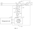
FIG. 5 is a schematic circuit diagram of a power supply circuit according to a third embodiment of the present disclosure. -
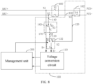
FIG. 6 is a schematic circuit diagram of a power supply circuit according to a fourth embodiment of the present disclosure. -
FIG. 7 is another schematic circuit diagram of a power supply circuit according to a fourth embodiment of the present disclosure. -
FIG. 8 is a schematic circuit diagram of a power supply circuit according to a fifth embodiment of the present disclosure. -
FIG. 9 is a schematic circuit diagram of a power supply circuit according to a sixth embodiment of the present disclosure. -
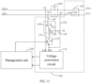
FIG. 10 is a schematic circuit diagram of a power supply circuit according to a seventh embodiment of the present disclosure. -
FIG. 11 is a schematic circuit diagram of a power supply circuit according to an eighth embodiment of the present disclosure. -
FIG. 12 is a schematic circuit diagram of a power supply circuit according to a ninth embodiment of the present disclosure. -
FIG. 13 is a schematic diagram of a connection of a power supply circuit and an external circuit according to the present disclosure. -
FIG. 14 is a schematic circuit diagram of a power supply circuit according to a tenth embodiment of the present disclosure. -
FIG. 15 is a schematic circuit diagram of a power supply circuit according to an eleventh embodiment of the present disclosure. -
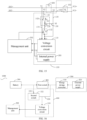
FIG. 16 is a schematic diagram of an energy storage device according to an embodiment of the present disclosure. - Embodiments of the present disclosure will be described in detail below with reference to the described embodiments as illustrated in the accompanying drawings, throughout which same or similar elements, or elements having same or similar functions, are denoted by same or similar reference numerals. The embodiments described below with reference to the drawings are illustrative only, and are intended to explain, rather than limiting, the present disclosure.
- In the related art, a cell monitor unit (CMU) is responsible for measuring parameters of a battery, such as a voltage, current, and temperature, and then transmitting the parameters to a battery management unit (BMU). The BMU is responsible for evaluating data transmitted by the CMU. If the data is abnormal, protection is performed on the battery and a request for lowering a current is issued, or a charging or discharging path is cut off, to prevent the battery from exceeding permissible conditions of use. Meanwhile, power and temperature of the battery are also managed.
- In the related art, some types of batteries are generally self-powered. For example, a household energy storage battery is self-powered. In a self-powered battery, a voltage output by the battery is output to the CMU for power supply after passing through a micro circuit breaker (MCB), enabling the CMU to operate to monitor the battery. However, after the MCB is disconnected manually or disconnected due to faults, the battery is disconnected from a power supply circuit of the CMU, and a CMU board cannot operate normally. In this way, even if when a fault occurs or even potential safety hazards occur in the battery, the CMU cannot monitor the battery, easily resulting in damage to the battery or the occurrence of safety issues in the battery.
- Referring to
FIG. 1 , an embodiment of the present disclosure provides apower supply circuit 100 for supplying power to amanagement unit 300 of abattery 200. Thebattery 200 is connected to anexternal circuit 500 by asafety protection switch 400. Thepower supply circuit 100 includes avoltage conversion circuit 110, afirst line 120, and asecond line 130. Thevoltage conversion circuit 110 is connected to two terminals of thesafety protection switch 400 by thefirst line 120 and thesecond line 130, respectively. Thevoltage conversion circuit 110 is configured to convert, when thesafety protection switch 400 is switched on, an output voltage of thebattery 200 into an operating voltage of themanagement unit 300 through thefirst line 120, and supply power to themanagement unit 300. Thesecond line 130 includes afirst switch 132. Thefirst switch 132 is configured to be switched on when thesafety protection switch 400 is switched off, to cause thevoltage conversion circuit 110 to supply power to themanagement unit 300 via thesecond line 130. - In an exemplary embodiment of the present disclosure, the
power supply circuit 100 has two power supply loops. In one of the two power supply loops, thebattery 200 is connected to thevoltage conversion circuit 110 by thesafety protection switch 400 and thefirst line 120, and thevoltage conversion circuit 110 converts an output voltage of thebattery 200 into the operating voltage of themanagement unit 300 to supply power to themanagement unit 300. In another power supply loop, thebattery 200 is connected to thevoltage conversion circuit 110 by thesecond line 130, and thevoltage conversion circuit 110 converts the output voltage of thebattery 200 into the operating voltage of themanagement unit 300 to supply power to themanagement unit 300. - The
safety protection switch 400 is configured to control thebattery 200 to be connected to or disconnected from theexternal circuit 500. Thebattery 200 exchanges electric energy with theexternal circuit 500 through thesafety protection switch 400. When thesafety protection switch 400 is switched on, thebattery 200 may discharge theexternal circuit 500, and theexternal circuit 500 may also charge thebattery 200. - The
safety protection switch 400 may be a micro circuit breaker (MCB), and the MCB may be manually disconnected or be disconnected due to a fault. For example, in a case where thebattery 200 is connected to theexternal circuit 500, when an input current or an output current of thebattery 200 is great, the MCB is disconnected due to overcurrent. - When the
safety protection switch 400 is switched off, thebattery 200 cannot be connected to thevoltage conversion circuit 110 by thefirst line 120. In this case, when thefirst switch 132 is switched on, thebattery 200 may be connected to thevoltage conversion circuit 110 by thesecond line 130 to supply power to themanagement unit 300 to allow themanagement unit 300 to operate normally. Thefirst switch 132 may be a button switch that is manually controllable. When thesafety protection switch 400 is switched off, thefirst switch 132 may be manually controlled to be switched on to allow themanagement unit 300 to operate normally. - Further, referring to
FIG. 2 , a BAT+ terminal may be configured to be connected to a positive pole of thebattery 200, and a BAT- terminal may be configured to be connected to a negative pole of thebattery 200. PCS+ may be configured to be connected to a positive pole of theexternal circuit 500, and PCS- may be configured to be connected to a negative pole of theexternal circuit 500. A B+ terminal may be configured to be connected to a positive pole of thevoltage conversion circuit 110, and a B- terminal may be configured to be connected to a negative pole of thevoltage conversion circuit 110. - The
safety protection switch 400 may include a switch S1, and thefirst switch 132 may include a switch S2. Thefirst line 120 may be a connection line between a third node N3 and the B- terminal, and thesecond line 130 may be a connection line between a fourth node N4 and the B- terminal. The BAT+ terminal may be connected to the B+ terminal through a first node N1, and the BAT- terminal may be connected to the B- terminal through thefirst line 120 or thesecond line 130. - When the switch S1 is switched on, the BAT- terminal may be connected to the B-terminal through the third node N3, i.e., the BAT- terminal may be connected to the B-terminal by the
first line 120. Meanwhile, the BAT+ terminal is connected to the B+ terminal through the first node N1. In this case, the output voltage of thebattery 200 is accessed to thevoltage conversion circuit 110. Thevoltage conversion circuit 110 may convert the output voltage of thebattery 200 into the operating voltage of themanagement unit 300 and supply power to themanagement unit 300. - Referring to
FIG. 3 , when the switch S1 is switched off, the BAT+ terminal and the third node N3 is disconnected from each other, and the BAT- terminal cannot be connected to the B- terminal through the third node N3, i.e., the BAT+ terminal cannot be connected to the B- terminal by thefirst line 120. In this case, the switch S2 may be controlled to be switched on, so that the BAT- terminal is connected to the B- terminal through the fourth node N4, i.e., the BAT- terminal may be connected to the B- terminal by thesecond line 130. Meanwhile, the BAT+ terminal is connected to the B+ terminal through the first node N1. In this case, the output voltage of thebattery 200 is accessed to thevoltage conversion circuit 110. Thevoltage conversion circuit 110 may convert the output voltage of thebattery 200 into the operating voltage of themanagement unit 300 and supply power to themanagement unit 300. - In this way, the
battery 200 can be connected to thevoltage conversion circuit 110 through two power supply loops. When thesafety protection switch 400 is switched off, the output voltage of thebattery 200 may also be supplied to thevoltage conversion circuit 110 through thefirst switch 132, to allow thevoltage conversion circuit 110 to supply power to themanagement unit 300. Themanagement unit 300 can still operate normally to monitor thebattery 200. Therefore, the damage to thebattery 200 or the occurrence of the safety issues in thebattery 200 due to an inability of themanagement unit 300 to monitor thebattery 200 can be avoided when a fault or even potential safety hazards occur in thebattery 200. - Referring to
FIG. 4 , in some embodiments, themanagement unit 300 is configured to detect an operating state of thebattery 200. Themanagement unit 300 can control thefirst switch 132 to be switched off in response to an abnormal operating state of thebattery 200 being detected, to disconnect thevoltage conversion circuit 110 from thebattery 200. - In an exemplary embodiment of the present disclosure, the
management unit 300 may be configured to measure a parameter such as a voltage, current, and temperature of thebattery 200, and determine the operating state of thebattery 200 based on the measurements. When the operating state of thebattery 200 is abnormal, protection may be performed on thebattery 200, to cause thebattery 200 to stop operating. After troubleshooting, thebattery 200 is re-controlled to operate. - When the
battery 200 has been stopped its operation, thebattery 200 cuts off a discharging path simultaneously, and the output voltage of thebattery 200 is no longer used for the power supply to themanagement unit 300 of thebattery 200. In this case, thesafety protection switch 100 is in an off state, i.e., the switch S1 is in an off state. In this case, if the switch S2 is controlled to be switched off, thevoltage conversion circuit 110 cannot be connected to thebattery 200 by thesecond line 130. Thevoltage conversion circuit 110 is disconnected from thebattery 200, to cause thebattery 200 to stop supplying power to themanagement unit 300. - When the
battery 200 has an insufficient power, thebattery 200 also needs to cut off the discharging path. For example, when thebattery 200 is charged by a charging device, thebattery 200 needs to cut off the discharging path, and thesafety protection switch 100 is in an off state. In this case, if the switch S2 is controlled to be switched off, as described above, thevoltage conversion circuit 110 is disconnected from thebattery 200, to cause thebattery 200 to stop supplying power to themanagement unit 300. - In this way, when the
battery 200 operates abnormally, thebattery 200 needs to cut off the discharging path. In this case, themanagement unit 300 controls thefirst switch 132 to be switched off, and thebattery 200 stops supplying power to themanagement unit 300. - Referring to
FIG. 5 , in some embodiments, thefirst switch 132 is a manual switch. - In an exemplary embodiment of the present disclosure, the
first switch 132 may include the switch S2 inFIG. 5 , and the switch S2 may be a manual switch. A user may manually switch off thefirst switch 132 as desired. For example, when the abnormal operating state of the battery is detected by the management unit, the management unit may send a corresponding alarm prompt signal to prompt the user. In this case, thesafety protection switch 100 is in an off state, i.e., the switch S1 is in an off state. - The user may control the switch S2 to be switched off to cut off the discharging path of the
battery 200 for the management unit, and the output voltage of thebattery 200 is no longer used for the power supply to themanagement unit 300 of thebattery 200. In this case, the switch S2 is controlled to be switched off, to cause the BAT- terminal and the B-terminal to be disconnected from each other. In this case, thevoltage conversion circuit 110 is disconnected from thebattery 200, so that thebattery 200 stops supplying power to themanagement unit 300. - When the insufficient power of the battery is detected by the management unit, the management unit may also send a corresponding alarm prompt signal to prompt the user. The user may control the switch S2 to be switched off to cut off the discharging path of the
battery 200 for the management unit, and the output voltage of thebattery 200 is no longer used for the power supply to themanagement unit 300 of thebattery 200. - Referring to
FIG. 6 , in some embodiments, thefirst switch 132 has a first terminal, a second terminal, and a third terminal. The first terminal is connected to thefirst line 120. The second terminal is connected to thesecond line 130. The third terminal is connected to thevoltage conversion circuit 110. Thefirst switch 132 is configured to selectively connect the third terminal to the first terminal or to the second terminal, or selectively disconnect the third terminal from the first terminal or from the second terminal. - In an exemplary embodiment of the present disclosure, the
first switch 132 may include a switch S2 shown inFIG. 6 . A first terminal of the switch S2 is connected to the third node N3, a second terminal of the switch S2 is connected to the fourth node N4, and a third terminal of the switch S2 is connected to the B- terminal. - When the first terminal is connected to the third terminal, the third node N3 may be connected to the B- terminal by the
first line 120. - If the switch S1 is switched on, the BAT- terminal may be connected to the third node N3, and connected to the B- terminal through the third node N3 and the switch S3. Meanwhile, the BAT+ terminal is connected to the B+ terminal through the first node N1. In this case, the output voltage of the
battery 200 is accessed to thevoltage conversion circuit 110. Thevoltage conversion circuit 110 may convert the output voltage of thebattery 200 into the operating voltage of themanagement unit 300 and supply power to themanagement unit 300. - If the switch S1 is switched off, the BAT- terminal cannot be connected to the third node N3, and the connection between the BAT- terminal and the B- terminal is disconnected. The
voltage conversion circuit 110 is disconnected from thebattery 200, so that thebattery 200 stops supplying power to themanagement unit 300. - Further, referring to
FIG. 7 , in a case where the second terminal is connected to the third terminal, the second node N2 may be connected to the B- terminal by thesecond line 130, and the BAT- terminal may be connected to the B- terminal through the second node N2. Meanwhile, the BAT+ terminal is connected to the B+ terminal through the first node N1. In this case, the output voltage of thebattery 200 is accessed to thevoltage conversion circuit 110. Thevoltage conversion circuit 110 may convert the output voltage of thebattery 200 into the operating voltage of themanagement unit 300 and supply power to themanagement unit 300. - Further, referring to
FIG. 8 , when the first terminal is disconnected from the third terminal and the second terminal is disconnected from the third terminal, the B- terminal cannot be connected to the BAT- terminal by thefirst line 120 and thesecond line 130, and the BAT- terminal and the B- terminal are disconnected from each other. Thevoltage conversion circuit 110 is disconnected from thebattery 200, causing thebattery 200 to stop supplying power to themanagement unit 300. - Referring to
FIG. 8 , in some embodiments, themanagement unit 300 is configured to detect the operating state of thebattery 200 and disconnect the third terminal from the first terminal and from the second terminal in response to the abnormal operating state of thebattery 200 being detected. - In an exemplary embodiment of the present disclosure, the
management unit 300 may control a connection state of the switch S3. When the abnormal operating state of thebattery 200 is detected by themanagement unit 300, thebattery 200 cuts off the charging and discharging path, and thebattery 200 cuts off a connection with theexternal circuit 500. In this case, the first terminal is disconnected from the third terminal, and the second terminal is disconnected from the third terminal. The B- terminal cannot be connected to the BAT-terminal by thefirst line 120 and thesecond line 130, and thus the BAT- terminal and the B-terminal are disconnected from each other. Thevoltage conversion circuit 110 is disconnected from thebattery 200, causing thebattery 200 to stop supplying power to themanagement unit 300. - Referring to
FIG. 9 , in some embodiments, thefirst switch 132 is a single-pole double-throw switch. - In an exemplary embodiment of the present disclosure, the switch S2 may be a manual single-pole double-throw switch. The user may selectively connect the third terminal to the first terminal or to the second terminal, or selectively disconnect the third terminal from the first terminal or from the second terminal, as desired.
- When the second terminal is connected to the third terminal, as described above, the
voltage conversion circuit 110 may convert the output voltage of thebattery 200 into the operating voltage of themanagement unit 300 and supply power to themanagement unit 300. - When the first terminal is disconnected from the third terminal and the second terminal is disconnected from the third terminal, as described above, the
voltage conversion circuit 110 is disconnected from thebattery 200, causing thebattery 200 to stop supplying power to themanagement unit 300. - Referring to
FIG. 10 , in some embodiments, thepower supply circuit 100 further includes athird line 140. Thebattery 200 is connected to thesecond line 130 by thethird line 140. The third line 40 includes asecond switch 142. Thebattery 200 is disconnected from thesecond line 130 when thesecond switch 142 is switched off. - When the
second switch 142 is switched off, thebattery 200 is disconnected from thesecond line 130, and thevoltage conversion circuit 110 cannot supply power to themanagement unit 300 through thesecond line 130. - In an exemplary embodiment of the present disclosure, the
third line 140 may be a connection line between the second node N2 and the fourth node N4, and thesecond switch 142 may include a switch S3. - When the switch S3 is switched off, the second node N2 and the fourth node N4 are disconnected from each other, and the BAT- terminal cannot be connected to the fourth node N4 through the second node N2. Further, the BAT- terminal cannot be connected to the B- terminal through the second node N2, the fourth node N4, and the switch S2, i.e., the BAT-terminal cannot be connected to the B- terminal by the
third line 140 and thesecond line 130. - As described above, when the switch S1 is switched off, the BAT- terminal cannot be connected to the B- terminal by the
first line 120. Therefore, when the switch S1 and the switch S3 are both switched off, the BAT- terminal cannot be connected to the B- terminal by thefirst line 120, and the BAT- terminal cannot be connected to the B- terminal by thesecond line 130, either. Thevoltage conversion circuit 110 is disconnected from thebattery 200, causing thebattery 200 to stop supplying power to themanagement unit 300. - Referring to
FIG. 11 , in some embodiments, the power supply circuit further includes afourth line 150. Thefourth line 150 is connected to thefirst line 120 and thethird line 140. When thesecond switch 142 is switched on, thebattery 200 is connected to thevoltage conversion circuit 110 by thethird line 140, thefourth line 150, and thefirst line 120. - In an exemplary embodiment of the present disclosure, the
fourth line 150 may be a connection line between the fourth node N4 and a fifth node N5. Thefourth line 150 is connected to thefirst line 120 through the fifth node N5, and thefourth line 150 is connected to thethird line 140 through the fourth node N4. - The fourth node N4 is connected to the fifth node N5, and the fifth node N5 is connected to the BAT- terminal. Further, the fourth node N4 is connected to the B- terminal. When the switch S3 is switched on, the BAT- terminal can be connected to the fourth node N4 through the second node N2, and the fourth node N4 is connected to the B- terminal. Thus, the BAT- terminal can be connected to the B- terminal through the fourth node N4. In this case, the
battery 200 is connected to thevoltage conversion circuit 110, and thevoltage conversion circuit 110 can convert the output voltage of thebattery 200 into the operating voltage of themanagement unit 300 and supply power to themanagement unit 300. - Referring to
FIG. 10 , in some embodiments, thesecond switch 142 includes a fourth terminal, a fifth terminal, and a sixth terminal. The fourth terminal is connected to the battery. The fifth terminal is suspended. The sixth terminal is connected to the second line. Thesecond switch 142 is configured to selectively connect the sixth terminal to the fourth terminal or to the fifth terminal, or selectively disconnect the sixth terminal from the fourth terminal or from the fifth terminal. - In an exemplary embodiment of the present disclosure, the
second switch 142 may include a switch S3. A fourth terminal of the switch S3 is connected to the second node N2, a fifth terminal of the switch S3 is suspended, and a sixth terminal of the switch S3 is connected to the fourth node N4. - When the fourth terminal is disconnected from the sixth terminal, the second node N2 and the fourth node N4 are disconnected from each other, and the BAT- terminal cannot be connected to the fourth node N4 through the second node N2. Further, the BAT- terminal cannot be connected to the B- terminal through the second node N2, the fourth node N4, and the switch S2, i.e., the BAT- terminal cannot be connected to the B- terminal by the
third line 140 and thesecond line 130. Thevoltage conversion circuit 110 is disconnected from thebattery 200, causing thebattery 200 to stop supplying power to themanagement unit 300. - Further, referring to
FIG. 12 , in a case where the fourth terminal is connected to the sixth terminal, the second node N2 may be connected to the fourth node N4 by thesecond line 142. If the switch S2 is switched on, the fourth node N4 may be connected to the B-terminal, and the BAT- terminal may be connected to the B- terminal through the second node N2 and the fourth node N4. In this case, thebattery 200 is connected to thevoltage conversion circuit 110, and thevoltage conversion circuit 110 can convert the output voltage of thebattery 200 into the operating voltage of themanagement unit 300 and supply power to themanagement unit 300. - Referring to
FIG. 12 , in some embodiments, thesecond switch 142 is a single pole double throw switch. - In an exemplary embodiment of the present disclosure, the
second switch 142 may be a manual single-pole double-throw switch. The user may selectively connect the sixth terminal to the fourth terminal or to the fifth terminal, or selectively disconnect the sixth terminal from the fourth terminal or from the fifth terminal, as desired. - When the fourth terminal is connected to the sixth terminal, and the switch S2 is switched on, as described above, the
voltage conversion circuit 110 may convert the output voltage of thebattery 200 into the operating voltage of themanagement unit 300 and supply power to themanagement unit 300. - When the fourth terminal is disconnected from the sixth terminal, and the switch S1 is switched off, as described above, the
voltage conversion circuit 110 is disconnected from thebattery 200, causing thebattery 200 to stop supplying power to themanagement unit 300. - Referring to
FIG. 13 , in some embodiments, theexternal circuit 500 includes anenergy storage converter 510 and anexternal power supply 520. When thesafety protection switch 400 is switched on, theexternal power supply 520 can charge the battery through theenergy storage converter 510. Thevoltage conversion circuit 110 is configured to convert, when thesafety protection switch 400 is switched on, an output voltage of theenergy storage converter 510 into the operating voltage of themanagement unit 300 through thefirst line 120 and supply power to themanagement unit 300. - In an exemplary embodiment of the present disclosure, when the
battery 200 has insufficient power, a voltage of theexternal power supply 520 may be accessed to theenergy storage converter 510 to supply power to thebattery 200. The battery may also supply power to a load connected to theexternal circuit 500 through theenergy storage converter 510. - The voltage of the
external power supply 520 may be accessed to theenergy storage converter 510 to supply power to themanagement unit 300. When thebattery 200 has insufficient power, theexternal power supply 520 may supply power to thebattery 200. - When the
external power supply 520 charges thebattery 200 through theenergy storage converter 510, themanagement unit 300 of thebattery 200 needs to monitor a charging of thebattery 200. Due to the insufficient power of thebattery 200, thebattery 200 cannot output a voltage to supply power to themanagement unit 300 of thebattery 200. In this case, the voltage of theexternal power supply 520 may be accessed to theenergy storage converter 510 to supply power to themanagement unit 300 of thebattery 200, to allow themanagement unit 300 to monitor a charging operation of thebattery 200. - Referring to
FIG. 14 , in some embodiments, thepower supply circuit 100 further includes afifth line 160. Thefifth line 160 is connected between the energy storage converter and thefirst line 120. Thefifth line 160 includes a third switch 152. The third switch 152 is configured to be switched on when thesafety protection switch 400 is switched on. - In an exemplary embodiment of the present disclosure, the third switch 152 may be a switch S4, and a line from the switch S1 to the PCS- is the
fifth line 160. PCS+ may be configured to be connected to a positive pole of theenergy storage converter 510, and the PCS may be configured to be connected to a negative pole of theenergy storage converter 510. - BAT+ is connected to PCS+ by the switch S1, and BAT- is connected to PCS- by the switch S1 and switch S4. When the switch S1 is switched on, the switch S4 is also switched on, to connect the BAT+ to the PCS+ and connect the BAT- to the PCS-. At this time, the
energy storage converter 510 is connected to thebattery 200. Therefore, theexternal circuit 500 can supply power to thebattery 200 through theenergy storage converter 510, or thebattery 200 can supply power to theexternal circuit 500 through theenergy storage converter 510. - Referring to
FIG. 14 , in some embodiments, thepower supply circuit 100 further includes asixth line 170. The positive pole of thebattery 200 is connected to thevoltage conversion circuit 110 by thesixth line 170, and the negative pole of thebattery 200 is connected to thevoltage conversion circuit 110 by thesecond line 130 and thethird line 140. The negative pole of thebattery 200 is also connected to thevoltage conversion circuit 110 by thefirst line 120. - In an exemplary embodiment of the present disclosure, a connection line between the first node N1 and the B+ terminal may be a sixth connection line. The B+ terminal may be directly connected to the BAT+ by the
sixth line 170. - Referring to
FIG. 15 , in some embodiments, thepower supply circuit 100 includes aninternal power supply 180. Theinternal power supply 180 is connected to themanagement unit 300 to supply power to themanagement unit 300. - In an exemplary embodiment of the present disclosure, the
management unit 300 of thebattery 200 has a correspondinginternal power supply 180. When thebattery 200 has insufficient power, theinternal power supply 180 may supply power to themanagement unit 300. In a case where the charging device charges thebattery 200, when thebattery 200 has insufficient power in such a manner that thebattery 200 cannot supply power to themanagement unit 300, theinternal power supply 180 may supply power to themanagement unit 300. Theinternal power supply 180 supplies power to themanagement unit 300 to allow themanagement unit 300 to operate normally and monitor the operating state of thebattery 200 during the charging. - An embodiment of the present disclosure provides a battery monitoring circuit. The battery monitoring circuit includes the
power supply circuit 100 according to any one of the above embodiments and themanagement unit 300. - In an exemplary embodiment of the present disclosure, during the operation of the
battery 200, thepower supply circuit 100 keeps supplying power to themanagement unit 300 to allow the management unit to always monitor the operating state of thebattery 200. Therefore, a protection can be activated by thepower supply circuit 100 in time when a fault or even potential safety hazards occur in thebattery 200. As a result, safety of thebattery 200 can be improved. - For embodiments of the
power supply circuit 100 and themanagement unit 300, reference may be made to the above embodiments, and beneficial effects of the battery monitoring circuit include all beneficial effects of thepower supply circuit 100 and themanagement unit 300, and details thereof are omitted herein. - Referring to
FIG. 16 , an embodiment of the present disclosure provides anenergy storage device 1000. Theenergy storage device 1000 includes the battery monitoring circuit according to any one of the above embodiments and abattery 200. - For embodiments of the battery monitoring circuit and the
battery 200, reference may be made to the foregoing embodiments, and beneficial effects of theenergy storage device 1000 include all beneficial effects of the battery monitoring circuit, and details thereof will be omitted herein. - In the
power supply circuit 100, the battery monitoring circuit, and theenergy storage device 1000 according to the embodiments of the present disclosure, thepower supply circuit 100 is configured to control thebattery 200 to supply power to themanagement unit 300 of thebattery 200. In one power supply loop, the voltage of thebattery 200 is accessed to to thevoltage conversion circuit 110 through thesafety protection switch 400 and thefirst line 120, and then thevoltage conversion circuit 110 converts the voltage of thebattery 200 into the operating voltage of themanagement unit 300 to supply power to themanagement unit 300. In another power supply loop, the voltage of thebattery 200 is accessed to thevoltage conversion circuit 110 through thesecond line 130, and then thevoltage conversion circuit 110 converts the voltage of thebattery 200 into the operating voltage of themanagement unit 300 to supply power to themanagement unit 300. When thesafety protection switch 400 is switched off, thebattery 200 cannot be connected to thevoltage conversion circuit 110 by thefirst line 120. In this case, when thefirst switch 132 is switched on, thebattery 200 can be connected to thevoltage conversion circuit 110 by thesecond line 130. As a result, the voltage of thebattery 200 can be accessed to thevoltage conversion circuit 110 through thesecond line 130, and then thevoltage conversion circuit 110 converts the voltage of thebattery 200 into the operating voltage of themanagement unit 300 to supply power to themanagement unit 300, so that themanagement unit 300 can operate normally. In this way, damage to thebattery 200 or occurrence of safety issue in thebattery 200 generated because themanagement unit 300 cannot monitor thebattery 200 can be avoided when a fault or even potential safety hazards occur in thebattery 200. - In the description of this specification, descriptions with reference to the terms "an embodiment," "some embodiments," "illustrative embodiments," "examples," "specific examples," or "some examples" etc., mean that specific features, structure, materials or characteristics described in conjunction with the embodiment or example are included in at least one embodiment or example of the present disclosure. In this specification, the schematic representations of the above terms do not necessarily refer to the same embodiment or example. In addition, those skilled in the art can combine the different embodiments or examples and the features of the different embodiments or examples described in this specification without contradicting each other.
- In addition, technical terms such as "connect to" should be understood in a broad sense. For example, it may be a fixed connection or a detachable connection or connection as one piece; a direct connection or an indirect connection through an intermediate; internal communication of two components. For those skilled in the art, the specific meaning of the above-mentioned terms in the present disclosure can be understood according to specific circumstances.
- In addition, the term "first" or "second" is only for descriptive purposes, rather than indicating or implying relative importance or implicitly indicating the number of indicated technical features. Therefore, the features associated with "first" or "second" can explicitly or implicitly include at least one of the features. In the description of the present disclosure, "plurality of" means at least two, unless otherwise specifically indicated.
- Any process or method described in a flowchart or described herein in other ways can be understood to include one or more modules, segments, or portions of codes of executable instructions for achieving specific logical functions or steps in the process. The scope of a preferred embodiment of the present disclosure includes other embodiments. A function may be performed not in a sequence shown or discussed, including a substantially simultaneous manner or a reverse sequence based on the function involved, which should be understood by those skilled in the art to which the embodiments of the present disclosure belong.
- Although embodiments according to the present disclosure have been shown and described, it would be appreciated by those skilled in the art that the above embodiments are illustrative and cannot be construed to limitation on the present disclosure, and changes, alternatives, modifications, and variations can be made in the embodiments without departing from scope of the present disclosure.
Claims (15)
- A power supply circuit (100) for supplying power to a management unit (300) of a battery (200), wherein the battery (200) is connected to an external circuit (500) by a safety protection switch (400), the power supply circuit (100) comprising:a first line (120);a second line (130); anda voltage conversion circuit (110) connected to two terminals of the safety protection switch (400) by the first line (120) and the second line (130) respectively, the voltage conversion circuit (110) being configured to convert an output voltage of the battery (200) into an operating voltage of the management unit (300) and supply power to the management unit (300),wherein the second line (130) comprises a first switch (132), the first switch (132) being configured to be switched on when the safety protection switch (400) is switched off, to cause the battery (200) to supply power to the management unit (300) by the voltage conversion circuit (110) via the second line (130).
- The power supply circuit (100) according to claim 1, wherein the first switch (132) is a manual switch that is manually switchable off by a user.
- The power supply circuit (100) according to claim 1, wherein:the first switch (132) has a first terminal connected to the battery (200), a second terminal connected to the first line (120), and a third terminal connected to the voltage conversion circuit (110); andthe first switch (132) is configured to selectively connect the third terminal to the first terminal or to the second terminal, or selectively disconnect the third terminal from the first terminal or from the second terminal.
- The power supply circuit (100) according to claim 3, wherein the first switch (132) is a single-pole double-throw switch.
- The power supply circuit (100) according to claim 1, further comprising a third line (140), the battery (200) being connected to the second line (130) by the third line (140),
wherein the third line (140) comprises a second switch (142), the battery (200) being disconnected from the second line (130) when the second switch (142) is switched off. - The power supply circuit (100) according to claim 5, further comprising a fourth line (150) connected to the first line (120) and the third line (140), the battery (200) being connected to the voltage conversion circuit (110) by the third line (140), the fourth line (150), and the first line (120) when the second switch (142) is switched on.
- The power supply circuit (100) according to claim 5, wherein:the second switch (142) has a fourth terminal connected to the battery (200), a fifth terminal that is suspended, and a sixth terminal connected to the second line (130); andthe second switch (142) is configured to selectively connect the sixth terminal to the fourth terminal or to the fifth terminal, or selectively disconnect the sixth terminal from the fourth terminal or from the fifth terminal.
- The power supply circuit (100) according to claim 7, wherein the second switch (142) is a single-pole double-throw switch.
- The power supply circuit (100) according to claim 1, wherein:
the voltage conversion circuit (110) is configured to convert, when the safety protection switch (400) is switched on, an output voltage of an energy storage converter (510) of the external circuit (500) into the operating voltage of the management unit (300) through the first line (120) and supply power to the management unit (300). - The power supply circuit (100) according to claim 1, further comprising a fifth line (160) connected between an energy storage converter (510) and the first line (120), the fifth line (160) comprising a third switch (152) configured to be switched on when the first switch (132) is switched on.
- The power supply circuit (100) according to claim 1, further comprising an internal power supply (180) connected to the management unit (300) to supply power to the management unit (300).
- A battery monitoring circuit, comprising:the power supply circuit (100) according to any one of claims 1 to 11; andthe management unit (300).
- The battery monitoring circuit according to claim 12, wherein the management unit (300) is configured to control the first switch (132) to be switched off in response to an abnormal operating state of the battery (200) being detected.
- The battery monitoring circuit according to claim 12 or 13, wherein:the first switch (132) has a first terminal connected to the battery (200), a second terminal connected to the first line (120), and a third terminal connected to the voltage conversion circuit (110);the first switch (132) is configured to selectively connect the third terminal to the first terminal or to the second terminal, or selectively disconnect the third terminal from the first terminal or from the second terminal; andthe management unit (300) is configured to disconnect the third terminal from the first terminal and from the second terminal in response to an abnormal operating state of the battery (200) being detected.
- An energy storage device, comprising:a battery (200); andthe battery monitoring circuit according to any one of claims 12 to 14.
Applications Claiming Priority (1)
| Application Number | Priority Date | Filing Date | Title |
|---|---|---|---|
| CN202322852056.7U CN221227182U (en) | 2023-10-23 | 2023-10-23 | Power supply circuit, battery monitoring circuit and energy storage device |
Publications (1)
| Publication Number | Publication Date |
|---|---|
| EP4546602A1 true EP4546602A1 (en) | 2025-04-30 |
Family
ID=91542395
Family Applications (1)
| Application Number | Title | Priority Date | Filing Date |
|---|---|---|---|
| EP24189293.4A Pending EP4546602A1 (en) | 2023-10-23 | 2024-07-17 | Power supply circuit, battery monitoring circuit, and energy storage device |
Country Status (5)
| Country | Link |
|---|---|
| US (1) | US20250132557A1 (en) |
| EP (1) | EP4546602A1 (en) |
| JP (1) | JP7723796B2 (en) |
| CN (1) | CN221227182U (en) |
| AU (1) | AU2024204691B2 (en) |
Citations (4)
| Publication number | Priority date | Publication date | Assignee | Title |
|---|---|---|---|---|
| EP3561992A1 (en) * | 2018-04-27 | 2019-10-30 | Permobil AB | Battery saving system and electrically powered mobility device comprising the same |
| US20200381917A1 (en) * | 2019-05-31 | 2020-12-03 | Mitsumi Electric Co., Ltd. | Secondary battery protection circuit, secondary battery protection apparatus and battery pack |
| US20210218070A1 (en) * | 2020-01-10 | 2021-07-15 | Lg Chem, Ltd. | Method for switch the mode of the battery pack from outside and the battery pack from the outside |
| KR20230061662A (en) * | 2021-10-28 | 2023-05-09 | 주식회사 엘지에너지솔루션 | Battery system and electric vehicle comprising the same |
Family Cites Families (2)
| Publication number | Priority date | Publication date | Assignee | Title |
|---|---|---|---|---|
| JPH11252822A (en) * | 1998-02-27 | 1999-09-17 | Nec Corp | Power supply device |
| JP6262418B2 (en) | 2012-08-23 | 2018-01-17 | Necプラットフォームズ株式会社 | POWER DIAGNOSIS DEVICE, POWER DIAGNOSIS SYSTEM, POWER DIAGNOSIS METHOD, AND POWER DIAGNOSIS PROGRAM |
-
2023
- 2023-10-23 CN CN202322852056.7U patent/CN221227182U/en active Active
-
2024
- 2024-05-22 JP JP2024082979A patent/JP7723796B2/en active Active
- 2024-07-05 US US18/764,412 patent/US20250132557A1/en active Pending
- 2024-07-07 AU AU2024204691A patent/AU2024204691B2/en active Active
- 2024-07-17 EP EP24189293.4A patent/EP4546602A1/en active Pending
Patent Citations (4)
| Publication number | Priority date | Publication date | Assignee | Title |
|---|---|---|---|---|
| EP3561992A1 (en) * | 2018-04-27 | 2019-10-30 | Permobil AB | Battery saving system and electrically powered mobility device comprising the same |
| US20200381917A1 (en) * | 2019-05-31 | 2020-12-03 | Mitsumi Electric Co., Ltd. | Secondary battery protection circuit, secondary battery protection apparatus and battery pack |
| US20210218070A1 (en) * | 2020-01-10 | 2021-07-15 | Lg Chem, Ltd. | Method for switch the mode of the battery pack from outside and the battery pack from the outside |
| KR20230061662A (en) * | 2021-10-28 | 2023-05-09 | 주식회사 엘지에너지솔루션 | Battery system and electric vehicle comprising the same |
Also Published As
| Publication number | Publication date |
|---|---|
| US20250132557A1 (en) | 2025-04-24 |
| CN221227182U (en) | 2024-06-25 |
| AU2024204691A1 (en) | 2025-05-08 |
| JP7723796B2 (en) | 2025-08-14 |
| AU2024204691B2 (en) | 2025-12-04 |
| JP2025071762A (en) | 2025-05-08 |
Similar Documents
| Publication | Publication Date | Title |
|---|---|---|
| CN111525642B (en) | A low-voltage parallel battery management system and method | |
| EP3767731B1 (en) | Battery pack and charging bank | |
| CN102570558B (en) | Intelligent charger of nickel-hydrogen nickel-cadmium battery and control method thereof | |
| CN109245283B (en) | Standby battery monitoring system and uninterrupted power supply intelligent switching and monitoring system | |
| US20060097696A1 (en) | Method and system for cell equalization with isolated charging sources | |
| KR101786347B1 (en) | Vehicle electric power system for jump start | |
| US20240222983A1 (en) | Lithium battery supporting series-parallel | |
| JP2009011081A (en) | Power system | |
| EP4546602A1 (en) | Power supply circuit, battery monitoring circuit, and energy storage device | |
| CN116031977A (en) | Battery management system and electric appliance | |
| WO2019053786A1 (en) | Storage battery device | |
| CN112531853B (en) | Main battery system management unit and protection method of battery single cabinet group parallel charging and discharging system | |
| CN102263432A (en) | Gush-surplus lithium battery storage battery | |
| CN211605342U (en) | Base station retired battery intelligent management system | |
| CN104578294B (en) | Control device, system, method and construction machinery for battery power supply system | |
| KR102765356B1 (en) | METHOD FOR BATTERY MONITORING AND CONTROLLING OF LiFePo4 BATTERY EMBEDDING POWER SUPPLY FOR 5G L2 SWITCH | |
| WO2025107465A1 (en) | Measurement and control module for intelligent charging and discharging, and charging and discharging system using module | |
| JP7313242B2 (en) | Battery pack and charging system | |
| CN117394282A (en) | A battery protection circuit | |
| CN212572106U (en) | Lead-acid storage battery system and device for preventing thermal runaway of lead-acid storage battery | |
| CN219041445U (en) | Battery management system and electric appliance | |
| KR102512062B1 (en) | Apparatus for controlling disconnecting switch and uninterruptible power supply including the same | |
| JP3583626B2 (en) | Charge / discharge device | |
| CN119944129B (en) | Battery system and its forced charge and discharge method | |
| CN223884958U (en) | A high-voltage box and energy storage system |
Legal Events
| Date | Code | Title | Description |
|---|---|---|---|
| PUAI | Public reference made under article 153(3) epc to a published international application that has entered the european phase |
Free format text: ORIGINAL CODE: 0009012 |
|
| STAA | Information on the status of an ep patent application or granted ep patent |
Free format text: STATUS: THE APPLICATION HAS BEEN PUBLISHED |
|
| AK | Designated contracting states |
Kind code of ref document: A1 Designated state(s): AL AT BE BG CH CY CZ DE DK EE ES FI FR GB GR HR HU IE IS IT LI LT LU LV MC ME MK MT NL NO PL PT RO RS SE SI SK SM TR |
|
| STAA | Information on the status of an ep patent application or granted ep patent |
Free format text: STATUS: REQUEST FOR EXAMINATION WAS MADE |
|
| 17P | Request for examination filed |
Effective date: 20251029 |