EP4546271A1 - Verfahren und vorrichtung zur erzeugung von 3d-bildern und computervorrichtung - Google Patents
Verfahren und vorrichtung zur erzeugung von 3d-bildern und computervorrichtung Download PDFInfo
- Publication number
- EP4546271A1 EP4546271A1 EP23826508.6A EP23826508A EP4546271A1 EP 4546271 A1 EP4546271 A1 EP 4546271A1 EP 23826508 A EP23826508 A EP 23826508A EP 4546271 A1 EP4546271 A1 EP 4546271A1
- Authority
- EP
- European Patent Office
- Prior art keywords
- image
- target
- color image
- initial
- rotation angle
- Prior art date
- Legal status (The legal status is an assumption and is not a legal conclusion. Google has not performed a legal analysis and makes no representation as to the accuracy of the status listed.)
- Pending
Links
Images


Classifications
-
- G—PHYSICS
- G06—COMPUTING OR CALCULATING; COUNTING
- G06T—IMAGE DATA PROCESSING OR GENERATION, IN GENERAL
- G06T17/00—Three dimensional [3D] modelling, e.g. data description of 3D objects
-
- H—ELECTRICITY
- H04—ELECTRIC COMMUNICATION TECHNIQUE
- H04N—PICTORIAL COMMUNICATION, e.g. TELEVISION
- H04N13/00—Stereoscopic video systems; Multi-view video systems; Details thereof
- H04N13/10—Processing, recording or transmission of stereoscopic or multi-view image signals
- H04N13/106—Processing image signals
- H04N13/128—Adjusting depth or disparity
-
- G—PHYSICS
- G06—COMPUTING OR CALCULATING; COUNTING
- G06T—IMAGE DATA PROCESSING OR GENERATION, IN GENERAL
- G06T15/00—3D [Three Dimensional] image rendering
- G06T15/005—General purpose rendering architectures
-
- G—PHYSICS
- G06—COMPUTING OR CALCULATING; COUNTING
- G06T—IMAGE DATA PROCESSING OR GENERATION, IN GENERAL
- G06T15/00—3D [Three Dimensional] image rendering
- G06T15/10—Geometric effects
- G06T15/20—Perspective computation
-
- G—PHYSICS
- G06—COMPUTING OR CALCULATING; COUNTING
- G06T—IMAGE DATA PROCESSING OR GENERATION, IN GENERAL
- G06T3/00—Geometric image transformations in the plane of the image
- G06T3/40—Scaling of whole images or parts thereof, e.g. expanding or contracting
-
- G—PHYSICS
- G06—COMPUTING OR CALCULATING; COUNTING
- G06T—IMAGE DATA PROCESSING OR GENERATION, IN GENERAL
- G06T7/00—Image analysis
- G06T7/50—Depth or shape recovery
-
- G—PHYSICS
- G06—COMPUTING OR CALCULATING; COUNTING
- G06T—IMAGE DATA PROCESSING OR GENERATION, IN GENERAL
- G06T7/00—Image analysis
- G06T7/90—Determination of colour characteristics
-
- H—ELECTRICITY
- H04—ELECTRIC COMMUNICATION TECHNIQUE
- H04N—PICTORIAL COMMUNICATION, e.g. TELEVISION
- H04N13/00—Stereoscopic video systems; Multi-view video systems; Details thereof
- H04N13/10—Processing, recording or transmission of stereoscopic or multi-view image signals
- H04N13/106—Processing image signals
- H04N13/15—Processing image signals for colour aspects of image signals
-
- H—ELECTRICITY
- H04—ELECTRIC COMMUNICATION TECHNIQUE
- H04N—PICTORIAL COMMUNICATION, e.g. TELEVISION
- H04N13/00—Stereoscopic video systems; Multi-view video systems; Details thereof
- H04N13/20—Image signal generators
- H04N13/261—Image signal generators with monoscopic-to-stereoscopic image conversion
- H04N13/268—Image signal generators with monoscopic-to-stereoscopic image conversion based on depth image-based rendering [DIBR]
-
- G—PHYSICS
- G06—COMPUTING OR CALCULATING; COUNTING
- G06T—IMAGE DATA PROCESSING OR GENERATION, IN GENERAL
- G06T2207/00—Indexing scheme for image analysis or image enhancement
- G06T2207/10—Image acquisition modality
- G06T2207/10024—Color image
-
- G—PHYSICS
- G06—COMPUTING OR CALCULATING; COUNTING
- G06T—IMAGE DATA PROCESSING OR GENERATION, IN GENERAL
- G06T2207/00—Indexing scheme for image analysis or image enhancement
- G06T2207/10—Image acquisition modality
- G06T2207/10028—Range image; Depth image; 3D point clouds
-
- H—ELECTRICITY
- H04—ELECTRIC COMMUNICATION TECHNIQUE
- H04N—PICTORIAL COMMUNICATION, e.g. TELEVISION
- H04N13/00—Stereoscopic video systems; Multi-view video systems; Details thereof
- H04N2013/0074—Stereoscopic image analysis
- H04N2013/0077—Colour aspects
Definitions
- the present application relates to the technical field of image processing, and in particular to a 3D image generating method, a 3D image generating apparatus and a computer device.
- 3D display technology With the development of science and technology, products applying 3D display technology have been widely used in people's daily lives. 3D videos applying 3D display technology have a strong visual impact and can bring immersive experiences to consumers.
- products applying 3D display technology usually convert a 2D video into a 3D video for stereoscopic display through a view conversion method.
- the 3D video obtained from a 2D video through the view conversion method does not present a perfect 3D display effect and is easy to cause blurring which degrades the users' viewing experience.
- the present application provides a 3D image generating method, an apparatus and a computer device to get more clearer 3D image and improve users' viewing experience.
- a first aspect of the embodiments of the present application provides a 3D image generating method, which includes:
- a second aspect of the embodiments of the present application provides a 3D generating apparatus, which includes:
- a third aspect of the embodiments of the present application provides a computer device which includes at least one processor, a memory and a transceiver connected therewith, the memory is configured to store program codes, and the processor is configured to call the program codes in the memory to execute the 3D image generating method mentioned above.
- the initial depth image of the 3D image to be generated is remapped to obtain the target depth image, and the relative displacement corresponding to the initial color image of the 3D image to be generated is determined. Then the initial color image is rendered according to the relative displacement and the target depth image to obtain the target color image, and the target color image and the initial color image are interleaved to generate the 3D image. In this way, a better and clearer 3D image can be got, which improves the users' viewing experience.
- the 3D image generating apparatus may be a server or a unit in the server, and is not specifically limited here.
- FIG. 1 a schematic flowchart of the 3D image generating method according to an embodiment of the present application is shown, and the 3D image generating method includes the following operations.
- an initial color image and an initial depth image are obtained from a back-end cache.
- modern 3D rendering frameworks (opengl ® , Metal ® , Vulkan ® , DirextX ® ) use dual/multiple cache technology. That is, the currently rendered image is not displayed on the screen in real time but stored in a back-end cache. The rendered content is displayed only after that the manager exchanges the contents between the front-end cache and back-end cache. Therefore, when the exchange is about to occur, a color image and a depth image in the back-end cache are obtained and re-rendered to generate images from other viewpoints, and a newly generated multi-viewpoint images, which are the content of the back-end cache, are exchanged with the content of the front-end cache.
- the 3D image generating apparatus can obtain the initial color image and the initial depth image which are to be displayed in 3D from the back-end cache.
- the initial color image and the initial depth image are related to each other, that is, the initial color image and the initial depth image are both obtained by converting a target original image.
- the target original image is an RGBD image including two images.
- One of the two images is an ordinary RGB three-channel color image including color information of a graphic.
- the other of the two image is a depth image including depth information.
- the original color image is an RGB three-channel color image and includes a plurality of pixels. Each of the pixels is represented by coordinate values (x, y), and each of the pixels has a pixel value representing RGB color information.
- the initial depth image is a depth image and includes a plurality of pixels.
- the pixels of the initial depth image have coordinate values corresponding to a target depth image.
- Each of the pixels of the initial depth image has a depth value representing depth information.
- the initial depth image is remapped to obtain a target depth image.
- the 3D image generating apparatus may remap the initial depth image to obtain the target depth image.
- D max is the maximum depth value of pixels of the initial depth image.
- MaxDepth is an empirical value, which can be 100 or another value, such as 80, 90 or 110, which is not specifically limited as long as it does not exceed the maximum floating-point value.
- the coordinate values of pixels of the target depth image obtained by remapping correspond to the coordinate values of pixels of the initial depth image one to one, and the depth value of the initial depth image and the depth value of the target depth image are different from each other.
- a relative displacement of the initial color image is determined.
- the 3D image generating apparatus can determine the relative displacement of the initial color image.
- the 3D image generating apparatus can determine a y-axis rotation angle and an x-axis rotation angle corresponding to the target original image.
- the target original image is an original image corresponding to the initial color image and the initial depth image.
- Rendering position information is determined according to the y-axis rotation angle and the x-axis rotation angle, and the relative displacement is determined according to the initial position information and the rendering position information.
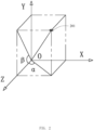
- FIG. 2 is a schematic diagram showing an angle between a human eye and a screen according to an embodiment of the present application.
- the label 201 represents a position of the human eye.
- an angle ⁇ is formed between a projection of a line on an XOZ plane and a positive z axis, the line is started from a user's eye to the center of the display screen, and an angle ⁇ is formed between a projection of the line on a YOZ plane and the positive z axis.
- a direction of an x-axis is identical to a left-right direction of the display screen, and a positive direction of the x-axis points from a center of a left part of the display screen to a center of a right part of the display screen.
- a direction of a y-axis is identical to a up-down direction of the display screen, and a positive direction of the y-axis points from a center of an upper part of the display screen to a center of a lower part of the display screen.
- a distance H from the user's eye to the display screen, and a distance J from a center of a scene corresponding to the target original image to the display screen a rotated angle a of the scene corresponding to the target original image around the y-axis (namely a "y-axis rotation angle" corresponding to the target original image) and a rotated angle b of the scene corresponding to the target original image around the x-axis (namely an "x-axis rotation angle" corresponding to the target original image) can be calculated.
- the display screen is the screen for displaying the 3D image
- the first target projection is the projection of the target connection line on the XOZ plane
- the target connection line is the line from the user's eye to the center of the display screen.
- the second target projection is the projection of the target connection line on the YOZ plane.
- the 3D image display device can determine the rendering position information according to the y-axis rotation angle and the x-axis rotation angle.
- the preset constant Rd can be 100 or 1000, which is not specifically limited and can be any value set according to the actual situation.
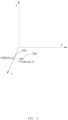
- FIG. 3 is a schematic diagram showing the relative displacement according to the embodiment of the present application.
- a coordinate point C 0 is where the camera 301 was located, and is the initial position information of the target original image.
- the camera 301 was located in a three-dimensional space defined by the x-axis, the y-axis and the z-axis, and the coordinate point C 0 has coordinate values (0, 0, z). Different rendered images can be obtained by changing the position of the camera 301.
- the position of camera 301 was remained unchanged on the z-axis.
- the changed position of the camera 301 was at a coordinate point C 1, that is, the coordinate point C 1 is the rendering position information, and the coordinate point C 1 has coordinate values (nx, ny, z ).
- the initial color image is rendered based on the relative displacement and the target depth image to obtain a target color image.
- the 3D image generating apparatus can render the initial color image based on the relative displacement and the target depth image to obtain the target color image, and the process is detailed in the following.
- an initial point cloud corresponding to the target depth image is determined.
- the coordinate values P 1( x, y, z ) of the point are obtained by adding D to the coordinate values P 0(x,y,z) . Since the position of the camera was remained unchanged on the z-axis and D has values (nx, ny, 0), z-values of the coordinate values of the target point cloud and the initial point cloud are the same.
- the reference image is a depth image that matches the size of the target depth image, and is initially assigned with a depth value A.
- Each point of the target point cloud is calculated according to the following formulas to obtain the reference image:
- Z x y min Z IP . x + 1 , IP . y + 1 , FltErr ;
- FltErr A ⁇ w / 2 / z 0 ;
- IP LP + Dis ⁇ DLP ;
- Dis PP ⁇ LP ⁇ PN ;
- DLP ⁇ LP , where Z is the reference image, Z(x,y) is a depth value of a pixel with coordinate values ( x,y ) in the reference image, Z ( IP.
- x+1, IP .y+1 is a depth value of a pixel with coordinate values (( IP. x+1, IP .y+1) in the reference image, min means to assign Z (x,y) with a smaller one of Z ( IP x+1, IP .y+1) IP.y +1) and FltErr ;
- A is an initial depth value of the reference image
- W is the width of the target depth image
- (x0, y0, z0) are the coordinate values of any point in the target point cloud, IP.x is the x-value of the coordinate values of the point IP, and IP.y is the y-value of the coordinate values of the point IP.
- the reference image is a depth image with the same size as the target depth image.
- the initial depth value of the reference image is A.
- the initial depth value A can be 100000, 90000, or 110000 which is not specifically limited as long as the initial depth value A is greater than the depth value of the target depth image and less than the maximum floating-point value.
- pixels of the initial color image is processed according to depth values of pixels of the reference image to obtain the target color image.
- I c ( x,y ) is a pixel value of a pixel with coordinate values (x,y) in the initial color image, and Z (x,y) is a depth value of a pixel with coordinate values (x,y) in the reference image.
- I c1 ( IP.x,IP.y ) is the pixel value of the pixel with coordinate values ( IP.x, IP.y ) in the target color image.
- the 3D image generating apparatus can determine whether there are a hole in the target color image, and the process of which is detailed below.
- the 3D image generating apparatus determines whether a pixel of the target color image is a hole based on a depth value of a pixel of the hole-filling depth image. Coordinate values of the pixel of the target color image is identical to coordinate values of the pixel of the hole-filling depth image. Pixels that are holes in the target color image are determined as target pixels.
- the determining of a target pixel in the target color image is detailed below.
- the pixel with coordinate values (x,y) in the target color image is determined as the target pixel which is a hole, where I d2 represents the hole-filling depth image, I d2 (x,y ) is a depth value of a reference pixel with coordinate values (x, y) in the hole-filling depth image. That is, in a condition that I d2 (x,y ) ⁇ 0 is met, the pixel value of the pixel with coordinate values (x,y) in the target color image is 0, and for the color value is zero, the pixel is a hole.
- the 3D image generating apparatus determines a hole filling value of the target pixel according to coordinate values and a depth value of each pixel in the hole-filling depth image, and the process of which is detailed below.
- preset paths can be determined according to the actual situation.
- the preset paths can be 16, 6, or 5, which are not specifically limited.
- the preset paths can be determined based on the generating of the target 3D image.
- 16 preset paths are taken as examples to detail the traversal method.
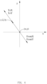
- FIG. 4 is a schematic diagram showing a preset path according to an embodiment of the present application.
- the preset paths are traversed based on coordinate values of each pixel in the hole-filling depth image, and a first target pixel and a second target pixel that meet the preset condition are determined.
- FromX FromX ⁇ Dirs i 0
- FromY FromY ⁇ Dirs i 1 .
- the negative direction traversal is performed until I d2 (FromX,FromY)> 0 is met or one of FromX and FromY exceeds the boundary of the hole-filling depth image.
- [i] in Dirs [i][ 0 ] and Dirs [i][1] represents the preset path to be traversed
- [0] means that a value of Dirs [ i ][ 0 ] is equal to a left one of coordinate values of the preset path.
- [1] means that a value of Dirs[i ][1] is equal to a right one of the coordinate values of the preset path.
- the positive direction traversal is performed until I d2 ( ToX,ToY ) >0 is met or one of ToX and ToY exceeds the boundary of the hole-filling depth image.
- [i] in Dirs[i][0] and Dirs[i][1] represents the preset path to be traversed
- [0] means that the value of Dirs [ i ][0] is equal to a left one of coordinate values of the preset path.
- [1] means that a value of Dirs [ i ][1] is equal to a right one of the coordinate values of the preset path.
- FLOAT_ MAX is the maximum floating-point value.
- the hole filling value of the target pixel is determined according to the coordinate values of the first target pixel and the coordinate values of the second target pixel.
- I d2 ( FromX,FromY ) is the depth value of the first target pixel
- I d2 ToX,ToY ) is the depth value of the second target pixel
- the hole filling value is assigned to the target pixel to fill the hole in the target color image, and the target color image without holes is obtained.
- a 3D image is generated according to the target color image and the initial color image.
- the 3D image generating apparatus scales the target color image and the initial color image to obtain a left color image and a right color image correspondingly, that is, the 3D image generating apparatus scales the initial color image to a size (w/2, h) to obtain the left color image, and scales the target color image to the size (w/2, h) to obtain the right color image, and then the left color image is rewritten to a left half area Rect(0, 0, w/2, h) of the back-end cache, and the right color image is written to the right half area Rect(w/2, 0, w/2, h) of the back-end cache.
- contents of the left half area of the back-end cache and contents of the right half area of the back-end cache are interleaved to obtain the 3D image and then the 3D image is output.
- the initial depth image of the 3D image to be generated is remapped to obtain the target depth image, and the relative displacement corresponding to the initial color image of the 3D image to be generated is determined. Then the initial color image is rendered according to the relative displacement and the target depth image to obtain the target color image, and the target color image and the initial color image are interleaved to generate the 3D image. In this way, a better and clearer 3D image can be got, which improves the users' viewing experience.
- the present application is described above from the perspective of a 3D image generating method, and the present application is described below from the perspective of the 3D image generating apparatus.
- FIG. 5 is a schematic structural diagram of a 3D image generating apparatus provided by an embodiment of the present application.
- the 3D image generating apparatus 400 includes:
- the determining unit 503 is further configured to:
- the determining unit 503 determining the rendering position information according to the y-axis rotation angle and the x-axis rotation angle includes:
- the determining unit 503 determining the y-axis rotation angle and the x-axis rotation angle corresponding to the target original image includes:
- the generating unit 505 is further configured to:
- the rendering unit 504 is further configured to:
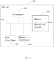
- FIG. 6 is a schematic structural diagram of a server of the present application.
- the server 600 in this embodiment includes at least one processor 601, at least one network interface 604 or another user interface 603, a memory 606, and at least one communication bus 602.
- the server 600 optionally includes the user interface 603, which can be a display, a keyboard, or a pointing device.
- the memory 605 may be a high-speed RAM memory, or may be a non-volatile memory, such as at least one disk memory.
- the memory 605 stores executable instructions.
- the processor 601 communicates with the memory 605, and the processor 601 invokes the instructions stored in the memory 605 to execute the above-mentioned 3D image generating method.
- the operating system 606 includes various programs for implementing various basic tasks and processing hardware-based tasks.
- the server provided by the embodiment of the present application can execute the above-mentioned embodiments of the 3D image generating method.
- the implementation principles and technical effects are similar to the above and will not be repeated here.
Landscapes
- Engineering & Computer Science (AREA)
- Physics & Mathematics (AREA)
- Theoretical Computer Science (AREA)
- General Physics & Mathematics (AREA)
- Computer Graphics (AREA)
- Geometry (AREA)
- Multimedia (AREA)
- Signal Processing (AREA)
- Computer Vision & Pattern Recognition (AREA)
- Software Systems (AREA)
- Computing Systems (AREA)
- Processing Or Creating Images (AREA)
- Image Processing (AREA)
- Image Generation (AREA)
Applications Claiming Priority (2)
| Application Number | Priority Date | Filing Date | Title |
|---|---|---|---|
| CN202210724366.8A CN115205451B (zh) | 2022-06-23 | 2022-06-23 | 3d图像的生成方法、装置及存储介质 |
| PCT/CN2023/101681 WO2023246863A1 (zh) | 2022-06-23 | 2023-06-21 | 3d图像的生成方法、装置及计算机设备 |
Publications (2)
| Publication Number | Publication Date |
|---|---|
| EP4546271A1 true EP4546271A1 (de) | 2025-04-30 |
| EP4546271A4 EP4546271A4 (de) | 2025-09-24 |
Family
ID=83578972
Family Applications (1)
| Application Number | Title | Priority Date | Filing Date |
|---|---|---|---|
| EP23826508.6A Pending EP4546271A4 (de) | 2022-06-23 | 2023-06-21 | Verfahren und vorrichtung zur erzeugung von 3d-bildern und computervorrichtung |
Country Status (6)
| Country | Link |
|---|---|
| US (1) | US20250373769A1 (de) |
| EP (1) | EP4546271A4 (de) |
| JP (1) | JP2025519947A (de) |
| KR (1) | KR20250040958A (de) |
| CN (1) | CN115205451B (de) |
| WO (1) | WO2023246863A1 (de) |
Cited By (1)
| Publication number | Priority date | Publication date | Assignee | Title |
|---|---|---|---|---|
| EP4546270A4 (de) * | 2022-06-23 | 2025-08-27 | Future Tech Xiang Yang Co Ltd | Verfahren und vorrichtung zur erzeugung von 3d-bildern und computervorrichtung |
Families Citing this family (1)
| Publication number | Priority date | Publication date | Assignee | Title |
|---|---|---|---|---|
| CN115205451B (zh) * | 2022-06-23 | 2025-10-21 | 未来科技(襄阳)有限公司 | 3d图像的生成方法、装置及存储介质 |
Family Cites Families (10)
| Publication number | Priority date | Publication date | Assignee | Title |
|---|---|---|---|---|
| KR101590763B1 (ko) * | 2009-06-10 | 2016-02-02 | 삼성전자주식회사 | Depth map 오브젝트의 영역 확장을 이용한 3d 영상 생성 장치 및 방법 |
| US8643701B2 (en) * | 2009-11-18 | 2014-02-04 | University Of Illinois At Urbana-Champaign | System for executing 3D propagation for depth image-based rendering |
| KR101688153B1 (ko) * | 2010-08-11 | 2016-12-20 | 엘지전자 주식회사 | 3차원 영상의 편집 방법 및 이를 이용하는 이동 단말기 |
| CN101937578B (zh) * | 2010-09-08 | 2012-07-04 | 宁波大学 | 一种虚拟视点彩色图像绘制方法 |
| US9137519B1 (en) * | 2012-01-04 | 2015-09-15 | Google Inc. | Generation of a stereo video from a mono video |
| CN104378617B (zh) * | 2014-10-30 | 2016-04-20 | 宁波大学 | 一种虚拟视点中像素点的获取方法 |
| CN111047709B (zh) * | 2019-11-29 | 2023-05-05 | 暨南大学 | 一种双目视觉裸眼3d图像生成方法 |
| EP4072147A4 (de) * | 2019-12-30 | 2022-12-14 | Huawei Technologies Co., Ltd. | Videostromverarbeitungsverfahren, gerät und vorrichtung und medium |
| CN113643414B (zh) * | 2020-05-11 | 2024-02-06 | 北京达佳互联信息技术有限公司 | 一种三维图像生成方法、装置、电子设备及存储介质 |
| CN115205451B (zh) * | 2022-06-23 | 2025-10-21 | 未来科技(襄阳)有限公司 | 3d图像的生成方法、装置及存储介质 |
-
2022
- 2022-06-23 CN CN202210724366.8A patent/CN115205451B/zh active Active
-
2023
- 2023-06-21 EP EP23826508.6A patent/EP4546271A4/de active Pending
- 2023-06-21 JP JP2024575733A patent/JP2025519947A/ja active Pending
- 2023-06-21 KR KR1020257002503A patent/KR20250040958A/ko active Pending
- 2023-06-21 WO PCT/CN2023/101681 patent/WO2023246863A1/zh not_active Ceased
-
2024
- 2024-12-20 US US18/989,323 patent/US20250373769A1/en active Pending
Cited By (1)
| Publication number | Priority date | Publication date | Assignee | Title |
|---|---|---|---|---|
| EP4546270A4 (de) * | 2022-06-23 | 2025-08-27 | Future Tech Xiang Yang Co Ltd | Verfahren und vorrichtung zur erzeugung von 3d-bildern und computervorrichtung |
Also Published As
| Publication number | Publication date |
|---|---|
| KR20250040958A (ko) | 2025-03-25 |
| CN115205451B (zh) | 2025-10-21 |
| WO2023246863A1 (zh) | 2023-12-28 |
| CN115205451A (zh) | 2022-10-18 |
| EP4546271A4 (de) | 2025-09-24 |
| US20250373769A1 (en) | 2025-12-04 |
| JP2025519947A (ja) | 2025-06-26 |
Similar Documents
| Publication | Publication Date | Title |
|---|---|---|
| US20250373769A1 (en) | 3d image generating method, apparatus and computer device | |
| CN111862295B (zh) | 一种虚拟对象的展示方法、装置、设备和存储介质 | |
| US10776997B2 (en) | Rendering an image from computer graphics using two rendering computing devices | |
| US20130286015A1 (en) | Optimal depth mapping | |
| CN101635061B (zh) | 基于人眼立体视觉机制的自适应立体渲染方法 | |
| WO2019040221A1 (en) | RENDERING AN IMAGE FROM COMPUTER GRAPHICS AND USING TWO RENDERING COMPUTER DEVICES | |
| KR100967296B1 (ko) | 그래픽 인터페이스 및 스테레오스코픽 디스플레이용 그래픽데이터를 래스터라이즈하는 방법 | |
| US12100106B2 (en) | Stereoscopic rendering of virtual 3D objects | |
| GB2406252A (en) | Generation of texture maps for use in 3D computer graphics | |
| CN107562185B (zh) | 一种基于头戴vr设备的光场显示系统及实现方法 | |
| CN108765582B (zh) | 一种全景图片显示方法及设备 | |
| US20250118013A1 (en) | 3d image generating method, computer device and non-transitory storage medium | |
| CN114513646A (zh) | 一种三维虚拟场景中全景视频的生成方法及设备 | |
| KR101227155B1 (ko) | 저해상도 그래픽 영상을 고해상도 그래픽 영상으로 실시간 변환하는 그래픽 영상 처리 장치 및 방법 | |
| CN118397226A (zh) | 一种三维模型确定方法及电子设备 | |
| Borshukov | New algorithms for modeling and rendering architecture from photographs | |
| Devernay et al. | New view synthesis for stereo cinema by hybrid disparity remapping | |
| US11202053B2 (en) | Stereo-aware panorama conversion for immersive media | |
| Bao et al. | Superview 3D image warping for visibility gap errors | |
| Marrinan et al. | Image Synthesis from a Collection of Depth Enhanced Panoramas: Creating Interactive Extended Reality Experiences from Static Images | |
| Walia et al. | A computationally efficient framework for 3D warping technique | |
| CN114359504B (zh) | 一种三维模型的显示方法及采集设备 | |
| CN112804511B (zh) | 一种动态渲染全景视频的方法和装置 | |
| TWI902767B (zh) | 處理拆分渲染中的遮蔽之方法及裝置 | |
| CN119379893A (zh) | 一种改善实时渲染平行光阴影贴图效果的方法及装置 |
Legal Events
| Date | Code | Title | Description |
|---|---|---|---|
| STAA | Information on the status of an ep patent application or granted ep patent |
Free format text: STATUS: THE INTERNATIONAL PUBLICATION HAS BEEN MADE |
|
| PUAI | Public reference made under article 153(3) epc to a published international application that has entered the european phase |
Free format text: ORIGINAL CODE: 0009012 |
|
| STAA | Information on the status of an ep patent application or granted ep patent |
Free format text: STATUS: REQUEST FOR EXAMINATION WAS MADE |
|
| 17P | Request for examination filed |
Effective date: 20250115 |
|
| AK | Designated contracting states |
Kind code of ref document: A1 Designated state(s): AL AT BE BG CH CY CZ DE DK EE ES FI FR GB GR HR HU IE IS IT LI LT LU LV MC ME MK MT NL NO PL PT RO RS SE SI SK SM TR |
|
| A4 | Supplementary search report drawn up and despatched |
Effective date: 20250822 |
|
| RIC1 | Information provided on ipc code assigned before grant |
Ipc: G06T 17/00 20060101AFI20250818BHEP Ipc: G06T 15/00 20110101ALI20250818BHEP Ipc: H04N 13/128 20180101ALI20250818BHEP Ipc: H04N 13/268 20180101ALI20250818BHEP |
|
| DAV | Request for validation of the european patent (deleted) | ||
| DAX | Request for extension of the european patent (deleted) |