EP4545856A2 - Modular injector bolt for an engine - Google Patents
Modular injector bolt for an engine Download PDFInfo
- Publication number
- EP4545856A2 EP4545856A2 EP24208794.8A EP24208794A EP4545856A2 EP 4545856 A2 EP4545856 A2 EP 4545856A2 EP 24208794 A EP24208794 A EP 24208794A EP 4545856 A2 EP4545856 A2 EP 4545856A2
- Authority
- EP
- European Patent Office
- Prior art keywords
- fuel
- nozzle
- injector
- passage
- centerline
- Prior art date
- Legal status (The legal status is an assumption and is not a legal conclusion. Google has not performed a legal analysis and makes no representation as to the accuracy of the status listed.)
- Pending
Links
Images




Classifications
-
- F—MECHANICAL ENGINEERING; LIGHTING; HEATING; WEAPONS; BLASTING
- F23—COMBUSTION APPARATUS; COMBUSTION PROCESSES
- F23R—GENERATING COMBUSTION PRODUCTS OF HIGH PRESSURE OR HIGH VELOCITY, e.g. GAS-TURBINE COMBUSTION CHAMBERS
- F23R3/00—Continuous combustion chambers using liquid or gaseous fuel
- F23R3/28—Continuous combustion chambers using liquid or gaseous fuel characterised by the fuel supply
- F23R3/283—Attaching or cooling of fuel injecting means including supports for fuel injectors, stems, or lances
-
- F—MECHANICAL ENGINEERING; LIGHTING; HEATING; WEAPONS; BLASTING
- F23—COMBUSTION APPARATUS; COMBUSTION PROCESSES
- F23R—GENERATING COMBUSTION PRODUCTS OF HIGH PRESSURE OR HIGH VELOCITY, e.g. GAS-TURBINE COMBUSTION CHAMBERS
- F23R3/00—Continuous combustion chambers using liquid or gaseous fuel
- F23R3/28—Continuous combustion chambers using liquid or gaseous fuel characterised by the fuel supply
- F23R3/286—Continuous combustion chambers using liquid or gaseous fuel characterised by the fuel supply having fuel-air premixing devices
-
- F—MECHANICAL ENGINEERING; LIGHTING; HEATING; WEAPONS; BLASTING
- F02—COMBUSTION ENGINES; HOT-GAS OR COMBUSTION-PRODUCT ENGINE PLANTS
- F02C—GAS-TURBINE PLANTS; AIR INTAKES FOR JET-PROPULSION PLANTS; CONTROLLING FUEL SUPPLY IN AIR-BREATHING JET-PROPULSION PLANTS
- F02C7/00—Features, components parts, details or accessories, not provided for in, or of interest apart form groups F02C1/00 - F02C6/00; Air intakes for jet-propulsion plants
- F02C7/22—Fuel supply systems
-
- F—MECHANICAL ENGINEERING; LIGHTING; HEATING; WEAPONS; BLASTING
- F02—COMBUSTION ENGINES; HOT-GAS OR COMBUSTION-PRODUCT ENGINE PLANTS
- F02K—JET-PROPULSION PLANTS
- F02K9/00—Rocket-engine plants, i.e. plants carrying both fuel and oxidant therefor; Control thereof
- F02K9/42—Rocket-engine plants, i.e. plants carrying both fuel and oxidant therefor; Control thereof using liquid or gaseous propellants
- F02K9/44—Feeding propellants
- F02K9/52—Injectors
-
- F—MECHANICAL ENGINEERING; LIGHTING; HEATING; WEAPONS; BLASTING
- F02—COMBUSTION ENGINES; HOT-GAS OR COMBUSTION-PRODUCT ENGINE PLANTS
- F02M—SUPPLYING COMBUSTION ENGINES IN GENERAL WITH COMBUSTIBLE MIXTURES OR CONSTITUENTS THEREOF
- F02M61/00—Fuel-injectors not provided for in groups F02M39/00 - F02M57/00 or F02M67/00
- F02M61/16—Details not provided for in, or of interest apart from, the apparatus of groups F02M61/02 - F02M61/14
- F02M61/18—Injection nozzles, e.g. having valve seats; Details of valve member seated ends, not otherwise provided for
-
- F—MECHANICAL ENGINEERING; LIGHTING; HEATING; WEAPONS; BLASTING
- F23—COMBUSTION APPARATUS; COMBUSTION PROCESSES
- F23D—BURNERS
- F23D7/00—Burners in which drops of liquid fuel impinge on a surface
-
- F—MECHANICAL ENGINEERING; LIGHTING; HEATING; WEAPONS; BLASTING
- F23—COMBUSTION APPARATUS; COMBUSTION PROCESSES
- F23R—GENERATING COMBUSTION PRODUCTS OF HIGH PRESSURE OR HIGH VELOCITY, e.g. GAS-TURBINE COMBUSTION CHAMBERS
- F23R3/00—Continuous combustion chambers using liquid or gaseous fuel
- F23R3/02—Continuous combustion chambers using liquid or gaseous fuel characterised by the air-flow or gas-flow configuration
- F23R3/04—Air inlet arrangements
- F23R3/10—Air inlet arrangements for primary air
- F23R3/12—Air inlet arrangements for primary air inducing a vortex
- F23R3/14—Air inlet arrangements for primary air inducing a vortex by using swirl vanes
-
- F—MECHANICAL ENGINEERING; LIGHTING; HEATING; WEAPONS; BLASTING
- F23—COMBUSTION APPARATUS; COMBUSTION PROCESSES
- F23R—GENERATING COMBUSTION PRODUCTS OF HIGH PRESSURE OR HIGH VELOCITY, e.g. GAS-TURBINE COMBUSTION CHAMBERS
- F23R3/00—Continuous combustion chambers using liquid or gaseous fuel
- F23R3/28—Continuous combustion chambers using liquid or gaseous fuel characterised by the fuel supply
- F23R3/30—Continuous combustion chambers using liquid or gaseous fuel characterised by the fuel supply comprising fuel prevapourising devices
-
- F—MECHANICAL ENGINEERING; LIGHTING; HEATING; WEAPONS; BLASTING
- F23—COMBUSTION APPARATUS; COMBUSTION PROCESSES
- F23R—GENERATING COMBUSTION PRODUCTS OF HIGH PRESSURE OR HIGH VELOCITY, e.g. GAS-TURBINE COMBUSTION CHAMBERS
- F23R3/00—Continuous combustion chambers using liquid or gaseous fuel
- F23R3/28—Continuous combustion chambers using liquid or gaseous fuel characterised by the fuel supply
- F23R3/30—Continuous combustion chambers using liquid or gaseous fuel characterised by the fuel supply comprising fuel prevapourising devices
- F23R3/32—Continuous combustion chambers using liquid or gaseous fuel characterised by the fuel supply comprising fuel prevapourising devices being tubular
-
- F—MECHANICAL ENGINEERING; LIGHTING; HEATING; WEAPONS; BLASTING
- F23—COMBUSTION APPARATUS; COMBUSTION PROCESSES
- F23R—GENERATING COMBUSTION PRODUCTS OF HIGH PRESSURE OR HIGH VELOCITY, e.g. GAS-TURBINE COMBUSTION CHAMBERS
- F23R3/00—Continuous combustion chambers using liquid or gaseous fuel
- F23R3/28—Continuous combustion chambers using liquid or gaseous fuel characterised by the fuel supply
- F23R3/38—Continuous combustion chambers using liquid or gaseous fuel characterised by the fuel supply comprising rotary fuel injection means
Definitions
- This disclosure relates generally to fuel delivery and, more particularly, to a fuel injector for an engine.
- a typical gas turbine engine includes an array of fuel injectors.
- the fuel injectors are operable to inject fuel into a chamber of a combustor for combustion.
- the fuel injectors are located radially within an engine casing.
- Each fuel injector may be L-shaped with a radially extending support arm and an axially extending nozzle at an inner end of the support arm.
- the support arm is secured to the engine casing and the nozzle is mated with a respective opening in a bulkhead of the combustor. While such known fuel injectors have various benefits, these fuel injectors may be cumbersome to install and may require significant engine disassembly for fuel injector inspection, maintenance and/or replacement.
- an assembly for an engine.
- This engine assembly includes an engine structure and a fuel injector.
- the engine structure includes an injector receptacle and a fuel supply passage.
- the injector receptacle extends longitudinally through the engine structure along a centerline.
- the fuel supply passage extends laterally within the engine structure to the injector receptacle.
- the fuel injector is mated with the injector receptacle.
- the fuel injector includes a nozzle passage and a nozzle outlet.
- the nozzle passage spirals about the centerline within the fuel injector towards the nozzle outlet.
- the nozzle passage fluidly couples the nozzle outlet to the fuel supply passage.
- the nozzle passage spirals about the centerline within the fuel injector to the nozzle outlet.
- the nozzle passage spirals two or more rotations about the centerline within the fuel injector.
- the nozzle passage has a spiral diameter and a spiral pitch that is equal to or greater than the spiral diameter.
- the nozzle passage is a first nozzle passage
- the fuel injector further includes a second nozzle passage longitudinally overlapping the first nozzle passage, the second nozzle passage spirals about the centerline within the fuel injector towards the nozzle outlet, and the second nozzle passage fluidly couples the nozzle outlet to the fuel supply passage.
- the fuel injector further includes a fuel nozzle and a splash plate, the fuel nozzle includes the nozzle passage and the nozzle outlet, and the fuel injector is configured to direct fuel, received by the nozzle passage from the fuel supply passage, out of the fuel nozzle through the nozzle outlet to impinge against the splash plate.
- the splash plate comprises a frustoconical splash plate surface
- the fuel injector is configured to direct fuel out of the fuel nozzle through the nozzle outlet to impinge against the frustoconical splash plate surface.
- the injector receptacle extends longitudinally through the engine structure along the centerline to an interior surface of the engine structure, and the interior surface is angularly offset from the centerline by a first angle, and the frustoconical splash plate surface is angularly offset from the centerline by a second angle that is equal to or less than the first angle.
- the nozzle outlet is formed by a frustoconical nozzle surface that is longitudinally spaced from and parallel with the frustoconical splash plate surface.
- the fuel injector further includes a fuel nozzle and a splash plate
- the fuel nozzle includes the nozzle passage and the nozzle outlet
- the splash plate is disposed at a distal end of the fuel nozzle and laterally overlaps the nozzle outlet.
- the fuel injector further includes a fuel coupler disposed within the fuel injector receptacle adjacent the fuel supply passage, and the fuel coupler fluidly couples the fuel supply passage to the nozzle passage.
- the fuel coupler includes a tubular sidewall and a chamber within the tubular sidewall, a port extends laterally through the tubular sidewall, and the port is at least partially aligned with an orifice to the fuel supply passage, and the chamber is fluidly coupled with and between the port and the nozzle passage.
- the fuel injector is attached to the engine structure by a threaded interface.
- the fuel injector includes a base and a head connected to the base, the base projects longitudinally along the centerline into the injector receptacle, and the head is abutted longitudinally against a surface of the engine structure.
- the engine comprises a gas turbine engine
- the engine structure comprises a wall of a combustor of the gas turbine engine
- the centerline is parallel with or angularly offset from a centerline axis of the combustor by less than fifteen degrees.
- this engine assembly includes an engine structure and a fuel injector.
- the engine structure includes an injector receptacle and a fuel supply passage.
- the injector receptacle extends longitudinally through the engine structure along a centerline.
- the fuel supply passage extends laterally within the engine structure to the injector receptacle.
- the fuel injector is mated with the injector receptacle and is attached to the engine structure by a threaded interface.
- the fuel injector is configured as a monolithic body and includes a fuel nozzle and a splash plate.
- the splash plate includes a frustoconical splash plate surface.
- the fuel injector is configured to direct fuel, received by the nozzle passage from the fuel supply passage, out of the fuel nozzle to impinge against the frustoconical splash plate surface.
- the fuel nozzle includes an annular nozzle outlet and a plurality of spiral nozzle passages fluidly coupled in parallel between the annular nozzle outlet and the fuel supply passage.
- This engine assembly includes an engine structure and a fuel injector.
- the engine structure includes an injector receptacle, a fuel supply passage and a combustion chamber.
- the injector receptacle extends longitudinally through the engine structure along a longitudinal centerline to the combustion chamber.
- the fuel supply passage extends laterally within the engine structure to the injector receptacle.
- the longitudinal centerline is parallel with or angularly offset from a centerline axis of the engine structure by less than fifteen degrees.
- the fuel injector is mated with the injector receptacle and is attached to the engine structure by a threaded interface.
- the fuel injector includes a nozzle passage and a nozzle outlet.
- the nozzle passage extends longitudinally along the centerline within the fuel injector towards the nozzle outlet.
- the nozzle passage fluidly couples the nozzle outlet to the fuel supply passage.
- the nozzle passage comprises a spiral nozzle passage.
- the nozzle passage may be configured as or otherwise include a spiral nozzle passage.
- the fuel nozzle may include an annular nozzle outlet and a plurality of spiral nozzle passages fluidly coupled in parallel between the annular nozzle outlet and the fuel supply passage.
- the nozzle passage may spiral about the centerline within the fuel injector to the nozzle outlet.
- the nozzle passage may spiral two or more rotations about the centerline within the fuel injector.
- the nozzle passage may have a spiral diameter and a spiral pitch that is equal to or greater than the spiral diameter.
- the nozzle passage may have a spiral diameter and a spiral pitch that is less than the spiral diameter.
- the nozzle passage may be a first nozzle passage, and the fuel injector may also include a second nozzle passage longitudinally overlapping the first nozzle passage.
- the second nozzle passage may spiral about the centerline within the fuel injector towards the nozzle outlet.
- the second nozzle passage may fluidly couple the nozzle outlet to the fuel supply passage.
- the fuel injector may also include a fuel nozzle and a splash plate.
- the fuel nozzle may include the nozzle passage and the nozzle outlet.
- the fuel injector may be configured to direct fuel, received by the nozzle passage from the fuel supply passage, out of the fuel nozzle through the nozzle outlet to impinge against the splash plate.
- the splash plate may include a frustoconical splash plate surface.
- the fuel injector may be configured to direct fuel out of the fuel nozzle through the nozzle outlet to impinge against the frustoconical splash plate surface.
- the injector receptacle may extend longitudinally through the engine structure along the centerline to an interior surface of the engine structure.
- the interior surface may be angularly offset from the centerline by a first angle.
- the frustoconical splash plate surface may be angularly offset from the centerline by a second angle that is equal to or less than the first angle.
- the nozzle outlet may be formed by a frustoconical nozzle surface that is longitudinally spaced from and parallel with the frustoconical splash plate surface.
- the fuel injector may also include a fuel nozzle and a splash plate.
- the fuel nozzle may include the nozzle passage and the nozzle outlet.
- the splash plate may be disposed at a distal end of the fuel nozzle and laterally overlaps the nozzle outlet.
- the fuel injector may also include a fuel coupler disposed within the fuel injector receptacle adjacent the fuel supply passage.
- the fuel coupler may fluidly couple the fuel supply passage to the nozzle passage.
- the fuel coupler may include a tubular sidewall and a chamber within the tubular sidewall.
- a port may extend laterally through the tubular sidewall.
- the port may be at least partially aligned with an orifice to the fuel supply passage.
- the chamber may be fluidly coupled with and between the port and the nozzle passage.
- the fuel injector may be attached to the engine structure by a threaded interface.
- the fuel injector may be configured to be installed with or removed from the engine structure completely from an exterior of the engine structure.
- the fuel injector may include a base and a head connected to the base.
- the base may project longitudinally along the centerline into the injector receptacle.
- the head may be abutted longitudinally against a surface of the engine structure.
- the engine may be configured as or otherwise include a gas turbine engine.
- the engine structure may be configured as or otherwise include a wall of a combustor of the gas turbine engine.
- the centerline may be parallel with or angularly offset from a centerline axis of the combustor by less than fifteen degrees.
- the present disclosure may include any one or more of the individual features disclosed above and/or below alone or in any combination thereof.
- FIGS. 1 and 2 are sectional illustrations of an assembly 20 for an internal combustion (IC) engine.
- IC internal combustion
- the gas turbine engine may be a turbojet engine, a turbofan engine, a turboprop engine, a turboshaft engine, a propfan engine, a pusher fan engine or an auxiliary power unit (APU).
- the aircraft may be an airplane, a helicopter, a drone (e.g., an unmanned aerial vehicle (UAV)) or any other manned or unmanned aerial vehicle or system.
- UAV unmanned aerial vehicle
- the present disclosure is not limited to such exemplary engines nor to aircraft applications.
- the engine for example, may alternatively be an industrial turbine engine, a reciprocating piston engine, a rotary engine (e.g., a Wenkel engine), or any other type of engine where fuel is continuously or periodically injected into a combustion volume for combustion.
- the engine assembly 20 of FIGS. 1 and 2 includes a stationary engine structure 22 with a centerline axis 24. This engine assembly 20 also includes a removable / modular fuel injector 26 with a longitudinal centerline 28.
- the engine structure 22 of FIG. 3 extends circumferentially about (e.g., partially or completely around) the centerline axis 24.
- the engine structure 22 of FIG. 4 extends axially along the centerline axis 24.
- the engine structure 22 of FIGS. 3 and 4 includes an inner wall 30, an outer wall 32, a fuel injector mount 34, a fuel conduit 36 (see FIG. 3 ) and a fuel injector receptacle 38.
- the inner wall 30 may be configured as a wall of a combustor 43 (see also FIG. 11 ) within the engine such as a combustor bulkhead wall or a combustor liner wall.
- the inner wall 30 of FIGS. 3 and 4 has a thickness which extends from an inner surface 40 of the inner wall 30 to an outer surface 42 of the inner wall 30.
- the inner wall inner surface 40 forms a peripheral outer boundary of a combustion chamber 44 (or another combustion volume) within the engine combustor 43.
- the inner wall outer surface 42 forms a peripheral inner boundary of a diffuser plenum 46 (or another cavity or flowpath) between the inner wall 30 and the outer wall 32 and adjacent (e.g., surrounding) the engine combustor 43.
- the inner wall 30 extends circumferentially about (e.g., partially or completely around) the centerline axis 24.
- the inner wall 30 may also extend radially away from and/or axially along the centerline axis 24.
- the inner wall 30 of FIG. 4 for example, converges radially inward towards the centerline axis 24 as the inner wall 30 extends axially along the centerline axis 24.
- the inner wall 30 and its inner wall inner surface 40 are angularly offset from the centerline axis 24 by an included angle 48 when viewed, for example, in a first reference plane parallel with (e.g., including) the centerline axis 24 and/or the longitudinal centerline 28; e.g., plane of FIG. 4 .
- This inner wall angle 48 may be a non-zero acute angle such as between thirty degrees (30°) and eighty degrees (80°); e.g., forty-five degrees (45°), sixty degrees (60°), etc.
- the inner wall angle 48 may be a right angle where the inner wall 30 and its inner wall inner surface 40 are perpendicular to the centerline axis 24.
- the inner wall angle 48 may be a zero angle where the inner wall 30 and its inner wall inner surface 40 are parallel with the centerline axis 24.
- the outer wall 32 may be configured as a diffuser case (or another combustor section case).
- the outer wall 32 of FIGS. 3 and 4 for example, has a thickness which extends from an inner surface 50 of the outer wall 32 to an outer surface 52 of the outer wall 32.
- the outer wall inner surface 50 forms a peripheral outer boundary of the diffuser plenum 46.
- the outer wall outer surface 52 forms an exterior surface of the engine.
- the outer wall 32 extends circumferentially about (e.g., partially or completely around) the centerline axis 24.
- the outer wall 32 may also extend radially away from and/or axially along the centerline axis 24.
- outer wall angle 54 of FIG. 4 is equal to the inner wall angle 48.
- the outer wall angle 54 may be (e.g., slightly) greater or less than the inner wall angle 48.
- the injector mount 34 is configured for mounting the fuel injector 26 to the engine structure 22.
- the injector mount 34 of FIGS. 1 and 2 for example, is a tubular member of the engine structure 22 (e.g., a boss) configured to receive the fuel injector 26.
- the injector mount 34 projects longitudinally along the longitudinal centerline 28 out from the inner wall 30, through the outer wall 32, to a longitudinal distal end 56 of the injector mount 34.
- This injector mount 34 is connected to (e.g., formed integral with or otherwise attached to) the inner wall 30 and/or the outer wall 32.
- 3 and 4 extends circumferentially about (e.g., completely around) the longitudinal centerline 28, providing the injector mount 34 with a full-hoop (e.g., tubular) geometry.
- a tubular inner portion 58 of the injector mount 34 extends longitudinally across the diffuser plenum 46 from the outer wall 32 and its outer wall inner surface 50 to the inner wall 30 and its inner wall outer surface 42.
- a tubular outer portion 60 of the injector mount 34 projects longitudinally out from the outer wall 32 and its outer wall outer surface 52 to the mount distal end 56.
- a fuel supply passage 62 extends along a centerline 64 of the fuel supply passage 62 (e.g., laterally relative to the longitudinal centerline 28), through the fuel conduit 36 and a tubular sidewall 66 of the injector mount 34 and its mount outer portion 60, to a supply passage orifice 68.
- the supply passage orifice 68 of FIGS. 3 and 4 is configured as an outlet from the fuel supply passage 62 into the injector receptacle 38.
- the injector receptacle 38 is configured as an internal aperture (e.g., a bore) in the engine structure 22.
- the injector receptacle 38 extends longitudinally along the longitudinal centerline 28 through the engine structure 22 to and between an outer end 70 of the injector receptacle 38 and an inner end 72 of the injector receptacle 38, which receptacle inner end 72 is longitudinally opposite the receptacle outer end 70.
- the receptacle outer end 70 is arranged at the mount distal end 56.
- the receptacle inner end 72 is arranged at the inner wall inner surface 40.
- the injector receptacle 38 of FIGS. 3 and 4 thereby extends longitudinally along the longitudinal centerline 28 from the mount distal end 56, sequentially through (and may be formed by) the mount outer portion 60, the outer wall 32, the mount inner portion 58 and the inner wall 30, to the inner wall inner surface 40.
- the injector receptacle 38 of FIGS. 3 and 4 includes a threaded portion 74 and a non-threaded portion 76.
- the receptacle threaded portion 74 is a tapped portion of the mount sidewall 66 forming the injector receptacle 38.
- the receptacle threaded portion 74 is disposed at (e.g., on, adjacent or proximate) the receptacle outer end 70.
- the receptacle non-threaded portion 76 is an untapped (e.g., smooth, cylindrical) portion of the mount sidewall 66.
- the receptacle non-threaded portion 76 is disposed at the receptacle inner end 72.
- the supply passage orifice 68 is disposed along an intermediate region of the injector receptacle 38.
- the supply passage orifice 68 for example, is located longitudinally (e.g., midway) between the receptacle outer end 70 and the receptacle inner end 72 along the longitudinal centerline 28.
- the supply passage orifice 68 of FIGS. 3 and 4 in particular, is disposed in the untapped portion of the mount sidewall 66 - in the receptacle non-threaded portion 76.
- the fuel supply passage 62 is thereby fluidly coupled with the injector receptacle 38 and its non-threaded portion 76.
- the fuel injector 26 may be configured as a fuel injector plug; e.g., a fuel injector bolt.
- the fuel injector 26 of FIG. 5 extends longitudinally along the longitudinal centerline 28 between and to an outer end 78 of the fuel injector 26 and an inner end 80 of the fuel injector 26, which injector inner end 80 is longitudinally opposite the injector outer end 78.
- the fuel injector 26 of FIG. 5 includes a fuel injector head 82, a fuel injector base 84 and a splash plate 86, where the injector head 82 may be a head of the fuel injector plug and the injector base 84 may be a shank of the fuel injector plug.
- the injector head 82 is connected to the injector base 84 and arranged at the injector outer end 78.
- the injector head 82 may be configured with a wrenching feature 88.
- the injector head 82 of FIGS. 6 and 7A is configured with a recess 90 for receiving and mating with a tool (not shown) such as, but not limited to, a hex-head tool (e.g., an Allen wrench or drive).
- a tool such as, but not limited to, a hex-head tool (e.g., an Allen wrench or drive).
- the recess 90 projects longitudinally along the longitudinal centerline 28 partially into the injector head 82 from the injector outer end 78 to an inner distal end 92 of the wrenching feature 88.
- FIG. 7A has a polygonal cross-sectional geometry such as a hexagonal cross-sectional geometry when viewed, for example, in a second reference plane perpendicular to the longitudinal centerline 28; e.g., plane of FIG. 7A .
- the wrenching feature 88 is described above as an internal wrenching feature, the injector head 82 may also or alternatively be configured with an external wrenching feature.
- an exterior of the injector head 82 may be configured one or more flats (e.g., planer surfaces) to provide the head 80 with a polygonal cross-sectional geometry.
- the injector base 84 projects longitudinally along the longitudinal centerline 28 from the injector head 82 to the injector inner end 80.
- the injector base 84 of FIG. 5 includes a (e.g., threaded) fuel injector attachment 94, a fuel coupler 96 and a fuel nozzle 98.
- the injector attachment 94 is longitudinally between and connected to (e.g., formed integral with or otherwise attached to) the injector head 82 and the fuel coupler 96.
- the injector attachment 94 of FIG. 5 extends longitudinally along the longitudinal centerline 28 to and between the injector head 82 and the fuel coupler 96.
- the injector attachment 94 may be a solid portion of the fuel injector 26; see also FIG. 6 .
- the injector attachment 94 for example, may be configured without any pathways through which fluid (e.g., fuel) may travel (e.g., laterally and/or longitudinally) thereacross. More particularly, the fuel injector 26 of FIG. 5 is configured without any apertures, bores, channels, etc. extending laterally and/or longitudinally through the injector attachment 94.
- An exterior of the injector attachment 94 is configured with threads for mating with the receptacle threaded portion 74; see FIGS. 1 and 2 .
- the threaded exterior of the injector attachment 94 may be laterally (e.g., radially relative to the longitudinal centerline 28) recessed from the exterior of the injector head 82 such that a (e.g., annular) head shoulder 100 extends laterally between the exteriors and circumferentially around the longitudinal centerline 28.
- the fuel coupler 96 is longitudinally between and connected to (e.g., formed integral with or otherwise attached to) the injector attachment 94 and the fuel nozzle 98.
- the fuel coupler 96 of FIG. 6 extends longitudinally along the longitudinal centerline 28 to and between the injector attachment 94 and the fuel nozzle 98.
- the fuel coupler 96 is configured with a lateral width (e.g., a diameter) that is less than a lateral width (e.g., a diameter) of the injector attachment 94.
- the fuel coupler 96 includes one or more ports 102 (e.g., apertures, windows, pass-throughs, etc.) and an internal chamber 104 (e.g., a plenum or another internal volume).
- the ports 102 are arranged circumferentially about the longitudinal centerline 28.
- Each port 102 provides a flowpath from an exterior of the fuel coupler 96 into the internal chamber 104.
- Each port 102 of FIG. 8 projects laterally (e.g., radially relative to the longitudinal centerline 28) into the fuel coupler 96 from the exterior of the fuel coupler 96 to the internal chamber 104.
- the internal chamber 104 is laterally and longitudinally within the fuel coupler 96.
- the internal chamber 104 may be an internal bore within the fuel coupler 96.
- the fuel nozzle 98 is connected to the fuel coupler 96.
- the fuel nozzle 98 of FIG. 6 projects longitudinally along the longitudinal centerline 28 from the fuel coupler 96 to a distal end 106 (e.g., a tip) of the fuel nozzle 98 proximate the injector inner end 80.
- the fuel nozzle 98 is configured with a lateral width (e.g., a diameter) that is different (e.g., less) than the lateral width of the fuel coupler 96 at the distal end 106; however, the present disclosure is not limited thereto.
- the fuel nozzle 98 is configured with one or more spiral fuel nozzle passages 108 (e.g., parallel fuel passages) and a fuel nozzle outlet 110.
- the fuel nozzle 98 may also be configured with an internal bore 112.
- This internal bore 112 projects longitudinally along the longitudinal centerline 28 within the fuel nozzle 98 from the internal chamber 104 to the nozzle passages 108.
- the internal bore 112 may thereby fluidly couple the nozzle passages 108 to the internal chamber 104 in parallel.
- Each of the nozzle passages 108 spirals about the longitudinal centerline 28 within the fuel nozzle 98 towards the nozzle outlet 110.
- each of the nozzle passages 108 spirals multiple revolutions about the longitudinal centerline 28 from the internal bore 112 (or alternatively directly from the internal chamber 104) to the nozzle outlet 110.
- the nozzle passages 108 of FIG. 6 longitudinally overlap one another along the longitudinal centerline 28.
- the nozzle passages 108 may thereby be arranged with a double helical geometry about and along the longitudinal centerline 28, where each nozzle passage 108 fluidly couples the internal bore 112 and, thus, the internal chamber 104 to the nozzle outlet 110 independent of the other nozzle passage 108.
- the nozzle passages 108 form a fuel swirler within the fuel nozzle 98 at (e.g., just upstream of) the nozzle outlet 110.
- Each nozzle passage 108 has an outer spiral diameter 114 and a spiral pitch 116.
- the spiral diameter 114 may be uniform (e.g., constant) longitudinally along the longitudinal centerline 28.
- the spiral pitch 116 may be equal to or greater than the spiral diameter 114.
- the present disclosure is not limited to such an exemplary relationship.
- the spiral pitch 116 may alternatively be less than the spiral diameter 114.
- the spiral pitch 116 may be sized larger than the spiral diameter 114 to increase longitudinal forward momentum of fuel flowing through the nozzle passages 108.
- the nozzle outlet 110 is disposed at the nozzle distal end 106.
- This nozzle outlet 110 is configured as a port or an orifice which fluidly couples the nozzle passages 108 to an environment outside of the fuel injector 26 and its fuel nozzle 98; e.g., the combustion chamber 44 of FIGS. 1 and 2 .
- the nozzle outlet 110 thereby provides an outlet from the nozzle passages 108 and, more generally, from the fuel injector 26 and its fuel nozzle 98.
- the nozzle outlet 110 may be configured with a divergent geometry.
- An outer periphery of the nozzle outlet 110 of FIG. 7 for example, is formed by an annular outer nozzle surface 118; e.g., a frustoconical nozzle surface.
- This nozzle surface 118 extends circumferentially about (e.g., completely around) the longitudinal centerline 28.
- a radius of the nozzle surface 118 increases as the nozzle surface 118 extends longitudinally along the longitudinal centerline 28 from the nozzle passages 108 towards the injector inner end 80.
- the nozzle surface 118 is angularly offset from the longitudinal centerline 28 by an included angle 120 when viewed, for example, in the first reference plane; e.g., plane of FIG. 6 .
- This nozzle surface angle 120 is a non-zero acute angle greater than twenty degrees (20°); e.g., between twenty degrees (20°) and forty degrees (40°), between forty degrees (40°) and sixty degrees (60°), between sixty degrees (60°) and eighty degrees (80°).
- the present disclosure is not limited to such an exemplary relationship.
- the nozzle surface angle 120 may alternatively be a right angle (90°) in other select embodiments.
- the splash plate 86 is connected to (e.g., formed integral with or otherwise attached to) the fuel nozzle 98 at the injector inner end 80.
- the splash plate 86 has an annular splash plate surface 122 (e.g., a frustoconical splash plate surface) disposed longitudinally opposite the nozzle outlet 110.
- the splash plate surface 122 of FIG. 6 for example, is spaced longitudinally from the nozzle distal end 106 and the nozzle outlet 110 by a longitudinal distance.
- the splash plate surface 122 extends circumferentially about (e.g., completely around) the longitudinal centerline 28.
- the splash plate surface 122 projects radially out to a distal outer peripheral edge 124 (e.g., an outer rim) of the splash plate 86.
- a radius of the splash plate surface 122 increases as the splash plate 86 extends longitudinally along the longitudinal centerline 28 away from the nozzle outlet 110.
- the splash plate surface 122 is angularly offset from the longitudinal centerline 28 by an included angle 126 when viewed, for example, in the first reference plane; e.g., plane of FIG. 6 .
- This splash plate surface angle 126 may be equal to or less than the nozzle surface angle 120.
- the splash plate surface angle 126 for example, is a non-zero acute angle greater than twenty degrees (20°); e.g., between twenty degrees (20°) and forty degrees (40°), between forty degrees (40°) and sixty degrees (60°), between sixty degrees (60°) and eighty degrees (80°).
- the present disclosure is not limited to such an exemplary relationship.
- the radius of the splash plate surface 122 at the outer peripheral edge 124 of the splash plate 86 may be sized greater than a maximum radius of the nozzle outlet 110.
- the splash plate 86 and its splash plate surface 122 may thereby (e.g., completely) laterally overlap the nozzle outlet 110.
- the fuel injector 26 is mated with (e.g., disposed and/or threaded into) the injector receptacle 38.
- the fuel nozzle 98 is inserted longitudinally into the injector receptacle 38 at the receptacle outer end 70 (see also FIGS. 3 and 4 ).
- the fuel nozzle 98 is moved longitudinally through the receptacle threaded portion 74 and into the receptacle non-threaded portion 76.
- the external threads of the injector attachment 94 are mated with the internal threads of the receptacle threaded portion 74.
- the fuel injector 26 is threaded (e.g., screwed) into the injector receptacle 38 using a tool (not shown) until, for example, the head shoulder 100 is longitudinally abutted and preloaded direct against a surface 128 at the mount distal end 56, or indirectly against the mount distal end surface 128 through a washer (not shown).
- the fuel injector 26 is thereby removably attached to the engine structure 22 by a threaded interface between the interior threads on the mount sidewall 66 of the receptacle threaded portion 74 and the exterior threads on the injector attachment 94.
- the ports 102 may be configured with the fuel coupler 96 (e.g., sized and spaced around the longitudinal centerline 28) such that, for example, at least one of these ports 102 is at least partially (or completely) aligned with the supply passage orifice 68 no matter how the fuel nozzle 98 is clocked about the longitudinal centerline 28 within the injector receptacle 38.
- the injector attachment 94 and/or the fuel coupler 96 may be arranged completely within the injector receptacle 38.
- the fuel nozzle 98 may be arranged (e.g., partially or completely) within and/or outside of the injector receptacle 38. More particularly, the fuel nozzle 98 of FIGS. 1 and 2 projects longitudinally out from the injector receptacle 38, away from the inner wall inner surface 40 and into the combustion chamber 44.
- the fuel injector 26 may be installed with the engine structure 22 and removed from the engine structure 22 from an exterior of the engine structure 22. Assembly personnel, maintenance personnel and/or inspection personnel may thereby install, replace and/or service the fuel injector 26 without requiring disassembly and/or removal of the engine structure 22 nor access to an interior of the engine structure 22.
- Fuel injectors 26 with, for example, different fuel coupler configurations, fuel nozzle configurations, etc. may be more easily swapped. The plug-and-play operation of the fuel nozzle 98 reduces complexity of the fuel delivery system.
- a single step of mating the fuel injector 26 with the engine structure 22 may (A) fluidly couple the fuel injector 26 with the fuel conduit 36 as well as (B) position the fuel nozzle 98 for operation.
- the bolt-like design of the fuel injector 26 may simplify the mechanical connection between the fuel injector 26 and the engine structure 22.
- fuel is directed into the fuel supply passage 62 from a fuel source (not shown). At least a portion (or all) of the fuel within the fuel supply passage 62 is directed into the nozzle passages 108.
- the fuel flowing within the fuel nozzle 98 is swirled by the nozzle passages 108 and directed out of the fuel nozzle 98 through the nozzle outlet 110 into a spatial gap between (a) the fuel nozzle 98 and its nozzle outlet 110 and (b) the splash plate 86 and its splash plate surface 122 as a swirler fuel jet. This swirled fuel jet flows through the spatial gap and impacts (e.g., impinges against) the splash plate surface 122.
- the splash plate 86 Upon impacting the splash plate surface 122, the splash plate 86 redirects (e.g., disperses) the impinging fuel jet radially outward (relative to the longitudinal centerline 28) into a (e.g., uniform and/or symmetrical) disperse radiant pattern; e.g., an arcuate and/or a generally planar film.
- the fuel may thereby be more evenly dispersed / spread / mixed into fluid (e.g., air, fuel-air mixture, combustion products, etc.) within the combustion chamber 44. Providing such relatively even mixing of the fuel and the fluid may in turn increase fuel burn efficiency and/or reduce likelihood of carbon formation within the engine.
- the fuel injector 26 may be configured with one or more annular seal elements 130 and 132.
- Each seal element 130, 132 may be configured as a ring seal such as, but not limited to, an O-ring element, a C-seal element, a crush seal element, a washer, etc.
- the ports 102 and the supply passage orifice 68 of FIG. 1 are positioned longitudinally along the longitudinal centerline 28 between the outer seal element 130 and the inner seal element 132.
- the outer seal element 130 is seated in an annular outer seal receptacle 134 (e.g., a notch, a groove, a channel, etc.) in the injector base 84; see also FIGS. 5 and 6 .
- the outer seal receptacle 134 of FIG. 1 in particular, is located in an outer portion of the fuel coupler 96.
- the outer seal receptacle 134 may be located in an inner portion of the injector attachment 94, or in another portion of the fuel injector 26 and its injector base 84 longitudinally between the fuel coupler 96 and the injector attachment 94.
- the outer seal element 130 is laterally engaged with the injector base 84 and the mount sidewall 66 in the receptacle non-threaded portion 76.
- the outer seal element 130 may thereby form a seal interface between the fuel injector 26 and the engine structure 22 such that the fuel, for example, does not leak (e.g., in an outward direction) between the engine assembly elements into an external environment.
- the inner seal element 132 is seated in an annular inner seal receptacle 136 (e.g., a notch, a groove, a channel, etc.) in the injector base 84; see also FIGS. 5 and 6 .
- the inner seal receptacle 136 of FIG. 1 in particular, is located in an inner portion of the fuel coupler 96.
- the inner seal receptacle 136 may be located in an outer portion of the fuel nozzle 98, or in another portion of the fuel injector 26 and its injector base 84 longitudinally between the fuel coupler 96 and the fuel nozzle 98.
- the inner seal element 132 is laterally engaged with the injector base 84 and the mount sidewall 66 in the receptacle non-threaded portion 76.
- the inner seal element 132 may thereby form a seal interface between the fuel injector 26 and the engine structure 22 such that the fuel, for example, does not leak (e.g., in an inward direction) between the engine assembly elements into the combustion chamber 44.
- the longitudinal centerline 28 may be arranged parallel with the centerline axis 24. In other embodiments, the longitudinal centerline 28 may be angularly offset from the centerline axis 24 by less than ten or fifteen degrees (10-15°). The present disclosure, however, is not limited to such exemplary arrangements.
- the inner wall 30 and its inner wall inner surface 40 are angularly offset from the longitudinal centerline 28 by an included offset angle 138.
- the first wall offset angle 138 is equal to the inner wall angle 48 (see FIG. 4 ); however, the present disclosure is not limited to such an exemplary relationship.
- the splash plate surface angle 126 may be equal to or less than the first wall offset angle 138. With this arrangement, the fuel may be directed into the combustion chamber 44 by the splash plate 86, for example, without also impinging against and/or being substantially obstructed by and/or redirected by the inner wall 30 and its inner wall inner surface 40.
- the engine assembly 20 may include a plurality of the fuel injectors 26. These fuel injectors 26 may be arranged circumferentially about the centerline axis 24 in, for example, an annular array. Each of the fuel injectors 26 may be configured as described above.
- the engine structure 22 may also be generally configured as described above. However, the engine structure 22 may include a plurality of the fuel conduits 36 and a plurality of the injector mounts 34, where each injector mount 34 is configured to mount a respective one of the fuel injectors 26 with the engine structure 22.
- the fuel conduits 36 may be configured to collectively form a fuel supply (e.g., a manifold) for the fuel injectors 26.
- a fuel supply e.g., a manifold
- Each fuel conduit 36 of FIG. 10 is arranged between a respective circumferentially adjacent pair of the fuel injectors 26.
- Each injector mount 34 may be arranged circumferentially between and connected to respective circumferentially adjacent pair of the fuel conduits 36.
- each injector receptacle 38 see FIGS. 1 and 2
- the respective fuel injector 26 received therein is fluidly coupled with a respective pair of the fuel supply passages 62.
- each fuel injector 26 may be configured as a monolithic body.
- Each fuel injector 26 and its elements 82, 84 and 86 may be additively manufactured, cast, machined and/or otherwise forms as a single integral, unitary body.
- the engine structure 22 may also or alternatively be configured as a monolithic body.
- the engine structure 22 of FIGS. 1-4 and 10 for example, and each of its elements 30, 32, 34 and 36 may be additively manufactured, cast, machined and/or otherwise formed as a single integral, unitary body.
- a non-monolithic body may include parts that are discretely formed from one another, where those parts are subsequently mechanically fastened and/or otherwise attached to one another.
- FIG. 11 schematically illustrates a single spool, radial-flow turbojet turbine engine 140 with which the engine assembly 20 of FIGS. 1 , 2 and 10 may be included.
- This turbine engine 140 may be configured for propelling an unmanned aerial vehicle (UAV), a drone, or any other manned or unmanned aircraft or self-propelled projectile.
- UAV unmanned aerial vehicle
- the turbine engine 140 includes an upstream inlet 142, a (e.g., radial) compressor section 144, a combustor section 146, a (e.g., radial) turbine section 148 and a downstream exhaust 150 fluidly coupled in series.
- a compressor rotor 152 in the compressor section 146 is coupled with a turbine rotor 154 in the turbine section 148 by a shaft 156, which rotates about the centerline axis 24 of the turbine engine 140.
- the engine combustor 43 is disposed within the combustor section 146.
Landscapes
- Engineering & Computer Science (AREA)
- Chemical & Material Sciences (AREA)
- Combustion & Propulsion (AREA)
- Mechanical Engineering (AREA)
- General Engineering & Computer Science (AREA)
- Fuel-Injection Apparatus (AREA)
Abstract
Description
- This disclosure relates generally to fuel delivery and, more particularly, to a fuel injector for an engine.
- A typical gas turbine engine includes an array of fuel injectors. The fuel injectors are operable to inject fuel into a chamber of a combustor for combustion. The fuel injectors are located radially within an engine casing. Each fuel injector may be L-shaped with a radially extending support arm and an axially extending nozzle at an inner end of the support arm. The support arm is secured to the engine casing and the nozzle is mated with a respective opening in a bulkhead of the combustor. While such known fuel injectors have various benefits, these fuel injectors may be cumbersome to install and may require significant engine disassembly for fuel injector inspection, maintenance and/or replacement.
- It is also known in the art to form a fuel injector with a surrounding engine casing as a unitary body. While such an integral fuel injector configuration may simplify engine assembly, the fuel injector cannot be replaced without also replacing or modifying the engine casing.
- Thus, there is a need in the art for an improved fuel injector system.
- According to an aspect of the present invention, an assembly is provided for an engine. This engine assembly includes an engine structure and a fuel injector. The engine structure includes an injector receptacle and a fuel supply passage. The injector receptacle extends longitudinally through the engine structure along a centerline. The fuel supply passage extends laterally within the engine structure to the injector receptacle. The fuel injector is mated with the injector receptacle. The fuel injector includes a nozzle passage and a nozzle outlet. The nozzle passage spirals about the centerline within the fuel injector towards the nozzle outlet. The nozzle passage fluidly couples the nozzle outlet to the fuel supply passage.
- In an embodiment of the above, the nozzle passage spirals about the centerline within the fuel injector to the nozzle outlet.
- In a further embodiment of any of the above, the nozzle passage spirals two or more rotations about the centerline within the fuel injector.
- In a further embodiment of any of the above, the nozzle passage has a spiral diameter and a spiral pitch that is equal to or greater than the spiral diameter.
- In a further embodiment of any of the above, the nozzle passage is a first nozzle passage, and the fuel injector further includes a second nozzle passage longitudinally overlapping the first nozzle passage, the second nozzle passage spirals about the centerline within the fuel injector towards the nozzle outlet, and the second nozzle passage fluidly couples the nozzle outlet to the fuel supply passage.
- In a further embodiment of any of the above, the fuel injector further includes a fuel nozzle and a splash plate, the fuel nozzle includes the nozzle passage and the nozzle outlet, and the fuel injector is configured to direct fuel, received by the nozzle passage from the fuel supply passage, out of the fuel nozzle through the nozzle outlet to impinge against the splash plate.
- In a further embodiment of any of the above, the splash plate comprises a frustoconical splash plate surface, and the fuel injector is configured to direct fuel out of the fuel nozzle through the nozzle outlet to impinge against the frustoconical splash plate surface.
- In a further embodiment of any of the above, the injector receptacle extends longitudinally through the engine structure along the centerline to an interior surface of the engine structure, and the interior surface is angularly offset from the centerline by a first angle, and the frustoconical splash plate surface is angularly offset from the centerline by a second angle that is equal to or less than the first angle.
- In a further embodiment of any of the above, the nozzle outlet is formed by a frustoconical nozzle surface that is longitudinally spaced from and parallel with the frustoconical splash plate surface.
- In a further embodiment of any of the above, the fuel injector further includes a fuel nozzle and a splash plate, the fuel nozzle includes the nozzle passage and the nozzle outlet, and the splash plate is disposed at a distal end of the fuel nozzle and laterally overlaps the nozzle outlet.
- In a further embodiment of any of the above, the fuel injector further includes a fuel coupler disposed within the fuel injector receptacle adjacent the fuel supply passage, and the fuel coupler fluidly couples the fuel supply passage to the nozzle passage.
- In a further embodiment of any of the above, the fuel coupler includes a tubular sidewall and a chamber within the tubular sidewall, a port extends laterally through the tubular sidewall, and the port is at least partially aligned with an orifice to the fuel supply passage, and the chamber is fluidly coupled with and between the port and the nozzle passage.
- In a further embodiment of any of the above, the fuel injector is attached to the engine structure by a threaded interface.
- In a further embodiment of any of the above, the fuel injector includes a base and a head connected to the base, the base projects longitudinally along the centerline into the injector receptacle, and the head is abutted longitudinally against a surface of the engine structure.
- In a further embodiment of any of the above, the engine comprises a gas turbine engine, and the engine structure comprises a wall of a combustor of the gas turbine engine.
- In a further embodiment of any of the above, the centerline is parallel with or angularly offset from a centerline axis of the combustor by less than fifteen degrees.
- According to another aspect of the present invention, another assembly is provided for an engine. This engine assembly includes an engine structure and a fuel injector. The engine structure includes an injector receptacle and a fuel supply passage. The injector receptacle extends longitudinally through the engine structure along a centerline. The fuel supply passage extends laterally within the engine structure to the injector receptacle. The fuel injector is mated with the injector receptacle and is attached to the engine structure by a threaded interface. The fuel injector is configured as a monolithic body and includes a fuel nozzle and a splash plate. The splash plate includes a frustoconical splash plate surface. The fuel injector is configured to direct fuel, received by the nozzle passage from the fuel supply passage, out of the fuel nozzle to impinge against the frustoconical splash plate surface.
- In an embodiment of the above, the fuel nozzle includes an annular nozzle outlet and a plurality of spiral nozzle passages fluidly coupled in parallel between the annular nozzle outlet and the fuel supply passage.
- According to still another aspect of the present invention, another assembly is provided for an engine. This engine assembly includes an engine structure and a fuel injector. The engine structure includes an injector receptacle, a fuel supply passage and a combustion chamber. The injector receptacle extends longitudinally through the engine structure along a longitudinal centerline to the combustion chamber. The fuel supply passage extends laterally within the engine structure to the injector receptacle. The longitudinal centerline is parallel with or angularly offset from a centerline axis of the engine structure by less than fifteen degrees. The fuel injector is mated with the injector receptacle and is attached to the engine structure by a threaded interface. The fuel injector includes a nozzle passage and a nozzle outlet. The nozzle passage extends longitudinally along the centerline within the fuel injector towards the nozzle outlet. The nozzle passage fluidly couples the nozzle outlet to the fuel supply passage.
- In an embodiment of the above, the nozzle passage comprises a spiral nozzle passage.
- The nozzle passage may be configured as or otherwise include a spiral nozzle passage.
- The fuel nozzle may include an annular nozzle outlet and a plurality of spiral nozzle passages fluidly coupled in parallel between the annular nozzle outlet and the fuel supply passage.
- The nozzle passage may spiral about the centerline within the fuel injector to the nozzle outlet.
- The nozzle passage may spiral two or more rotations about the centerline within the fuel injector.
- The nozzle passage may have a spiral diameter and a spiral pitch that is equal to or greater than the spiral diameter.
- The nozzle passage may have a spiral diameter and a spiral pitch that is less than the spiral diameter.
- The nozzle passage may be a first nozzle passage, and the fuel injector may also include a second nozzle passage longitudinally overlapping the first nozzle passage. The second nozzle passage may spiral about the centerline within the fuel injector towards the nozzle outlet. The second nozzle passage may fluidly couple the nozzle outlet to the fuel supply passage.
- The fuel injector may also include a fuel nozzle and a splash plate. The fuel nozzle may include the nozzle passage and the nozzle outlet. The fuel injector may be configured to direct fuel, received by the nozzle passage from the fuel supply passage, out of the fuel nozzle through the nozzle outlet to impinge against the splash plate.
- The splash plate may include a frustoconical splash plate surface. The fuel injector may be configured to direct fuel out of the fuel nozzle through the nozzle outlet to impinge against the frustoconical splash plate surface.
- The injector receptacle may extend longitudinally through the engine structure along the centerline to an interior surface of the engine structure. The interior surface may be angularly offset from the centerline by a first angle. The frustoconical splash plate surface may be angularly offset from the centerline by a second angle that is equal to or less than the first angle.
- The nozzle outlet may be formed by a frustoconical nozzle surface that is longitudinally spaced from and parallel with the frustoconical splash plate surface.
- The fuel injector may also include a fuel nozzle and a splash plate. The fuel nozzle may include the nozzle passage and the nozzle outlet. The splash plate may be disposed at a distal end of the fuel nozzle and laterally overlaps the nozzle outlet.
- The fuel injector may also include a fuel coupler disposed within the fuel injector receptacle adjacent the fuel supply passage. The fuel coupler may fluidly couple the fuel supply passage to the nozzle passage.
- The fuel coupler may include a tubular sidewall and a chamber within the tubular sidewall. A port may extend laterally through the tubular sidewall. The port may be at least partially aligned with an orifice to the fuel supply passage. The chamber may be fluidly coupled with and between the port and the nozzle passage.
- The fuel injector may be attached to the engine structure by a threaded interface.
- The fuel injector may be configured to be installed with or removed from the engine structure completely from an exterior of the engine structure.
- The fuel injector may include a base and a head connected to the base. The base may project longitudinally along the centerline into the injector receptacle. The head may be abutted longitudinally against a surface of the engine structure.
- The engine may be configured as or otherwise include a gas turbine engine. The engine structure may be configured as or otherwise include a wall of a combustor of the gas turbine engine.
- The centerline may be parallel with or angularly offset from a centerline axis of the combustor by less than fifteen degrees.
- The present disclosure may include any one or more of the individual features disclosed above and/or below alone or in any combination thereof.
- The foregoing features and the operation of the invention will become more apparent in light of the following description and the accompanying drawings.
-
-
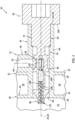
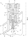
FIG. 1 is a plan view sectional illustration of a portion of an assembly for an internal combustion engine. -
FIG. 2 is another sectional illustration of a portion of the engine assembly. -
FIG. 3 is a plan view sectional illustration of a portion of an engine structure for the engine assembly. -
FIG. 4 is another section illustration of a portion of the engine structure. -
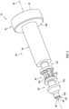
FIG. 5 is a perspective illustration of a fuel injector. -
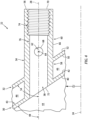
FIG. 6 is a sectional illustration of the fuel injector. -
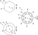
FIG. 7A is an illustration of a head of the fuel injector with an internal wrenching feature. -
FIG. 7B is an illustration of the fuel injector head with an external wrenching feature. -
FIG. 8 is a cross-sectional illustration of the fuel injector at its fuel coupler. -
FIG. 9 is a sectional illustration of a portion of the engine assembly ofFIG. 2 during engine operation. -
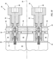
FIG. 10 is a plan view schematic illustration of another engine assembly configured with a plurality of the fuel injectors. -
FIG. 11 is a schematic side illustration of a single spool, radial-flow turbojet turbine engine. -
FIGS. 1 and2 are sectional illustrations of anassembly 20 for an internal combustion (IC) engine. For ease of description, this engine is described below as a gas turbine engine for an aircraft. The gas turbine engine may be a turbojet engine, a turbofan engine, a turboprop engine, a turboshaft engine, a propfan engine, a pusher fan engine or an auxiliary power unit (APU). The aircraft may be an airplane, a helicopter, a drone (e.g., an unmanned aerial vehicle (UAV)) or any other manned or unmanned aerial vehicle or system. The present disclosure, however, is not limited to such exemplary engines nor to aircraft applications. The engine, for example, may alternatively be an industrial turbine engine, a reciprocating piston engine, a rotary engine (e.g., a Wenkel engine), or any other type of engine where fuel is continuously or periodically injected into a combustion volume for combustion. - The
engine assembly 20 ofFIGS. 1 and2 includes astationary engine structure 22 with acenterline axis 24. Thisengine assembly 20 also includes a removable /modular fuel injector 26 with alongitudinal centerline 28. - The
engine structure 22 ofFIG. 3 extends circumferentially about (e.g., partially or completely around) thecenterline axis 24. Theengine structure 22 ofFIG. 4 extends axially along thecenterline axis 24. Theengine structure 22 ofFIGS. 3 and4 includes aninner wall 30, anouter wall 32, afuel injector mount 34, a fuel conduit 36 (seeFIG. 3 ) and afuel injector receptacle 38. - The
inner wall 30 may be configured as a wall of a combustor 43 (see alsoFIG. 11 ) within the engine such as a combustor bulkhead wall or a combustor liner wall. Theinner wall 30 ofFIGS. 3 and4 , for example, has a thickness which extends from aninner surface 40 of theinner wall 30 to anouter surface 42 of theinner wall 30. The inner wallinner surface 40 forms a peripheral outer boundary of a combustion chamber 44 (or another combustion volume) within theengine combustor 43. The inner wallouter surface 42 forms a peripheral inner boundary of a diffuser plenum 46 (or another cavity or flowpath) between theinner wall 30 and theouter wall 32 and adjacent (e.g., surrounding) theengine combustor 43. Theinner wall 30 extends circumferentially about (e.g., partially or completely around) thecenterline axis 24. Theinner wall 30 may also extend radially away from and/or axially along thecenterline axis 24. Theinner wall 30 ofFIG. 4 , for example, converges radially inward towards thecenterline axis 24 as theinner wall 30 extends axially along thecenterline axis 24. With this arrangement, theinner wall 30 and its inner wallinner surface 40 are angularly offset from thecenterline axis 24 by an includedangle 48 when viewed, for example, in a first reference plane parallel with (e.g., including) thecenterline axis 24 and/or thelongitudinal centerline 28; e.g., plane ofFIG. 4 . Thisinner wall angle 48 may be a non-zero acute angle such as between thirty degrees (30°) and eighty degrees (80°); e.g., forty-five degrees (45°), sixty degrees (60°), etc. Alternatively, theinner wall angle 48 may be a right angle where theinner wall 30 and its inner wallinner surface 40 are perpendicular to thecenterline axis 24. Still alternatively, it is contemplated theinner wall angle 48 may be a zero angle where theinner wall 30 and its inner wallinner surface 40 are parallel with thecenterline axis 24. - The
outer wall 32 may be configured as a diffuser case (or another combustor section case). Theouter wall 32 ofFIGS. 3 and4 , for example, has a thickness which extends from aninner surface 50 of theouter wall 32 to anouter surface 52 of theouter wall 32. The outer wallinner surface 50 forms a peripheral outer boundary of thediffuser plenum 46. The outer wallouter surface 52 forms an exterior surface of the engine. Theouter wall 32 extends circumferentially about (e.g., partially or completely around) thecenterline axis 24. Theouter wall 32 may also extend radially away from and/or axially along thecenterline axis 24. Theouter wall 32 ofFIG. 4 , for example, converges radially inward towards thecenterline axis 24 as theouter wall 32 extends axially along thecenterline axis 24. With this arrangement, theouter wall 32 and its outer wallinner surface 50 are angularly offset from thecenterline axis 24 by an includedangle 54 when viewed, for example, in the first reference plane. Thisouter wall angle 54 ofFIG. 4 is equal to theinner wall angle 48. However, in other embodiments, theouter wall angle 54 may be (e.g., slightly) greater or less than theinner wall angle 48. - Referring to
FIGS. 1 and2 , theinjector mount 34 is configured for mounting thefuel injector 26 to theengine structure 22. The injector mount 34 ofFIGS. 1 and2 , for example, is a tubular member of the engine structure 22 (e.g., a boss) configured to receive thefuel injector 26. Referring toFIGS. 3 and4 , the injector mount 34 projects longitudinally along thelongitudinal centerline 28 out from theinner wall 30, through theouter wall 32, to a longitudinaldistal end 56 of theinjector mount 34. This injector mount 34 is connected to (e.g., formed integral with or otherwise attached to) theinner wall 30 and/or theouter wall 32. The injector mount 34 ofFIGS. 3 and4 extends circumferentially about (e.g., completely around) thelongitudinal centerline 28, providing theinjector mount 34 with a full-hoop (e.g., tubular) geometry. With this arrangement, a tubularinner portion 58 of theinjector mount 34 extends longitudinally across thediffuser plenum 46 from theouter wall 32 and its outer wallinner surface 50 to theinner wall 30 and its inner wallouter surface 42. A tubularouter portion 60 of the injector mount 34 projects longitudinally out from theouter wall 32 and its outer wallouter surface 52 to the mountdistal end 56. - Referring to
FIG. 3 , thefuel conduit 36 is configured as or may otherwise be part of a fuel supply circuit for thefuel injector 26. Thefuel conduit 36, for example, may be or may be part of a fuel supply tube, a fuel inlet manifold and/or a fuel distribution manifold. Thefuel conduit 36 ofFIG. 3 is connected to (e.g., formed integral with or otherwise attached to) theouter wall 32 and is arranged at the outer wallouter surface 52. Thefuel conduit 36 extends circumferentially along theouter wall 32 to theinjector mount 34 and its mountouter portion 60. With this arrangement, afuel supply passage 62 extends along acenterline 64 of the fuel supply passage 62 (e.g., laterally relative to the longitudinal centerline 28), through thefuel conduit 36 and atubular sidewall 66 of theinjector mount 34 and its mountouter portion 60, to asupply passage orifice 68. Thesupply passage orifice 68 ofFIGS. 3 and4 is configured as an outlet from thefuel supply passage 62 into theinjector receptacle 38. - The
injector receptacle 38 is configured as an internal aperture (e.g., a bore) in theengine structure 22. Theinjector receptacle 38 extends longitudinally along thelongitudinal centerline 28 through theengine structure 22 to and between anouter end 70 of theinjector receptacle 38 and aninner end 72 of theinjector receptacle 38, which receptacleinner end 72 is longitudinally opposite the receptacleouter end 70. The receptacleouter end 70 is arranged at the mountdistal end 56. The receptacleinner end 72 is arranged at the inner wallinner surface 40. Theinjector receptacle 38 ofFIGS. 3 and4 thereby extends longitudinally along thelongitudinal centerline 28 from the mountdistal end 56, sequentially through (and may be formed by) the mountouter portion 60, theouter wall 32, the mountinner portion 58 and theinner wall 30, to the inner wallinner surface 40. - The
injector receptacle 38 ofFIGS. 3 and4 includes a threadedportion 74 and anon-threaded portion 76. The receptacle threadedportion 74 is a tapped portion of themount sidewall 66 forming theinjector receptacle 38. The receptacle threadedportion 74 is disposed at (e.g., on, adjacent or proximate) the receptacleouter end 70. The receptaclenon-threaded portion 76 is an untapped (e.g., smooth, cylindrical) portion of themount sidewall 66. The receptaclenon-threaded portion 76 is disposed at the receptacleinner end 72. - The
supply passage orifice 68 is disposed along an intermediate region of theinjector receptacle 38. Thesupply passage orifice 68, for example, is located longitudinally (e.g., midway) between the receptacleouter end 70 and the receptacleinner end 72 along thelongitudinal centerline 28. Thesupply passage orifice 68 ofFIGS. 3 and4 , in particular, is disposed in the untapped portion of the mount sidewall 66 - in the receptaclenon-threaded portion 76. Thefuel supply passage 62 is thereby fluidly coupled with theinjector receptacle 38 and itsnon-threaded portion 76. - Referring to
FIGS. 5 and6 , thefuel injector 26 may be configured as a fuel injector plug; e.g., a fuel injector bolt. Thefuel injector 26 ofFIG. 5 , for example, extends longitudinally along thelongitudinal centerline 28 between and to anouter end 78 of thefuel injector 26 and aninner end 80 of thefuel injector 26, which injectorinner end 80 is longitudinally opposite the injectorouter end 78. Thefuel injector 26 ofFIG. 5 includes afuel injector head 82, afuel injector base 84 and asplash plate 86, where theinjector head 82 may be a head of the fuel injector plug and theinjector base 84 may be a shank of the fuel injector plug. - The
injector head 82 is connected to theinjector base 84 and arranged at the injectorouter end 78. Referring toFIGS. 7A and 7B , theinjector head 82 may be configured with awrenching feature 88. Theinjector head 82 ofFIGS. 6 and7A , for example, is configured with arecess 90 for receiving and mating with a tool (not shown) such as, but not limited to, a hex-head tool (e.g., an Allen wrench or drive). Therecess 90 projects longitudinally along thelongitudinal centerline 28 partially into theinjector head 82 from the injectorouter end 78 to an innerdistal end 92 of thewrenching feature 88. Therecess 90 ofFIG. 7A has a polygonal cross-sectional geometry such as a hexagonal cross-sectional geometry when viewed, for example, in a second reference plane perpendicular to thelongitudinal centerline 28; e.g., plane ofFIG. 7A . While the wrenchingfeature 88 is described above as an internal wrenching feature, theinjector head 82 may also or alternatively be configured with an external wrenching feature. For example, referring toFIG. 7B , an exterior of theinjector head 82 may be configured one or more flats (e.g., planer surfaces) to provide thehead 80 with a polygonal cross-sectional geometry. - Referring to
FIG. 5 , theinjector base 84 projects longitudinally along thelongitudinal centerline 28 from theinjector head 82 to the injectorinner end 80. Theinjector base 84 ofFIG. 5 includes a (e.g., threaded)fuel injector attachment 94, afuel coupler 96 and afuel nozzle 98. - The
injector attachment 94 is longitudinally between and connected to (e.g., formed integral with or otherwise attached to) theinjector head 82 and thefuel coupler 96. Theinjector attachment 94 ofFIG. 5 , for example, extends longitudinally along thelongitudinal centerline 28 to and between theinjector head 82 and thefuel coupler 96. Theinjector attachment 94 may be a solid portion of thefuel injector 26; see alsoFIG. 6 . Theinjector attachment 94, for example, may be configured without any pathways through which fluid (e.g., fuel) may travel (e.g., laterally and/or longitudinally) thereacross. More particularly, thefuel injector 26 ofFIG. 5 is configured without any apertures, bores, channels, etc. extending laterally and/or longitudinally through theinjector attachment 94. - An exterior of the
injector attachment 94 is configured with threads for mating with the receptacle threadedportion 74; seeFIGS. 1 and2 . The threaded exterior of theinjector attachment 94 may be laterally (e.g., radially relative to the longitudinal centerline 28) recessed from the exterior of theinjector head 82 such that a (e.g., annular)head shoulder 100 extends laterally between the exteriors and circumferentially around thelongitudinal centerline 28. - Referring to
FIG. 6 , thefuel coupler 96 is longitudinally between and connected to (e.g., formed integral with or otherwise attached to) theinjector attachment 94 and thefuel nozzle 98. Thefuel coupler 96 ofFIG. 6 , for example, extends longitudinally along thelongitudinal centerline 28 to and between theinjector attachment 94 and thefuel nozzle 98. Thefuel coupler 96 is configured with a lateral width (e.g., a diameter) that is less than a lateral width (e.g., a diameter) of theinjector attachment 94. - The
fuel coupler 96 includes one or more ports 102 (e.g., apertures, windows, pass-throughs, etc.) and an internal chamber 104 (e.g., a plenum or another internal volume). Referring toFIG. 8 , theports 102 are arranged circumferentially about thelongitudinal centerline 28. Eachport 102 provides a flowpath from an exterior of thefuel coupler 96 into theinternal chamber 104. Eachport 102 ofFIG. 8 , for example, projects laterally (e.g., radially relative to the longitudinal centerline 28) into thefuel coupler 96 from the exterior of thefuel coupler 96 to theinternal chamber 104. Theinternal chamber 104 is laterally and longitudinally within thefuel coupler 96. Theinternal chamber 104, for example, may be an internal bore within thefuel coupler 96. - Referring to
FIG. 6 , thefuel nozzle 98 is connected to thefuel coupler 96. Thefuel nozzle 98 ofFIG. 6 , for example, projects longitudinally along thelongitudinal centerline 28 from thefuel coupler 96 to a distal end 106 (e.g., a tip) of thefuel nozzle 98 proximate the injectorinner end 80. Thefuel nozzle 98 is configured with a lateral width (e.g., a diameter) that is different (e.g., less) than the lateral width of thefuel coupler 96 at thedistal end 106; however, the present disclosure is not limited thereto. - The
fuel nozzle 98 is configured with one or more spiral fuel nozzle passages 108 (e.g., parallel fuel passages) and afuel nozzle outlet 110. Thefuel nozzle 98 may also be configured with aninternal bore 112. This internal bore 112 projects longitudinally along thelongitudinal centerline 28 within thefuel nozzle 98 from theinternal chamber 104 to thenozzle passages 108. Theinternal bore 112 may thereby fluidly couple thenozzle passages 108 to theinternal chamber 104 in parallel. Each of thenozzle passages 108 spirals about thelongitudinal centerline 28 within thefuel nozzle 98 towards thenozzle outlet 110. More particularly, each of thenozzle passages 108 spirals multiple revolutions about thelongitudinal centerline 28 from the internal bore 112 (or alternatively directly from the internal chamber 104) to thenozzle outlet 110. Thenozzle passages 108 ofFIG. 6 longitudinally overlap one another along thelongitudinal centerline 28. Thenozzle passages 108 may thereby be arranged with a double helical geometry about and along thelongitudinal centerline 28, where eachnozzle passage 108 fluidly couples theinternal bore 112 and, thus, theinternal chamber 104 to thenozzle outlet 110 independent of theother nozzle passage 108. With this arrangement, thenozzle passages 108 form a fuel swirler within thefuel nozzle 98 at (e.g., just upstream of) thenozzle outlet 110. - Each
nozzle passage 108 has anouter spiral diameter 114 and aspiral pitch 116. Thespiral diameter 114 may be uniform (e.g., constant) longitudinally along thelongitudinal centerline 28. Thespiral pitch 116 may be equal to or greater than thespiral diameter 114. The present disclosure, however, is not limited to such an exemplary relationship. Thespiral pitch 116, for example, may alternatively be less than thespiral diameter 114. Thespiral pitch 116 may be sized larger than thespiral diameter 114 to increase longitudinal forward momentum of fuel flowing through thenozzle passages 108. - The
nozzle outlet 110 is disposed at the nozzledistal end 106. Thisnozzle outlet 110 is configured as a port or an orifice which fluidly couples thenozzle passages 108 to an environment outside of thefuel injector 26 and itsfuel nozzle 98; e.g., thecombustion chamber 44 ofFIGS. 1 and2 . Thenozzle outlet 110 thereby provides an outlet from thenozzle passages 108 and, more generally, from thefuel injector 26 and itsfuel nozzle 98. Thenozzle outlet 110 may be configured with a divergent geometry. An outer periphery of thenozzle outlet 110 ofFIG. 7 , for example, is formed by an annularouter nozzle surface 118; e.g., a frustoconical nozzle surface. Thisnozzle surface 118 extends circumferentially about (e.g., completely around) thelongitudinal centerline 28. A radius of thenozzle surface 118 increases as thenozzle surface 118 extends longitudinally along thelongitudinal centerline 28 from thenozzle passages 108 towards the injectorinner end 80. With this arrangement, thenozzle surface 118 is angularly offset from thelongitudinal centerline 28 by an includedangle 120 when viewed, for example, in the first reference plane; e.g., plane ofFIG. 6 . Thisnozzle surface angle 120 is a non-zero acute angle greater than twenty degrees (20°); e.g., between twenty degrees (20°) and forty degrees (40°), between forty degrees (40°) and sixty degrees (60°), between sixty degrees (60°) and eighty degrees (80°). The present disclosure, however, is not limited to such an exemplary relationship. Thenozzle surface angle 120, for example, may alternatively be a right angle (90°) in other select embodiments. - The
splash plate 86 is connected to (e.g., formed integral with or otherwise attached to) thefuel nozzle 98 at the injectorinner end 80. Thesplash plate 86 has an annular splash plate surface 122 (e.g., a frustoconical splash plate surface) disposed longitudinally opposite thenozzle outlet 110. Thesplash plate surface 122 ofFIG. 6 , for example, is spaced longitudinally from the nozzledistal end 106 and thenozzle outlet 110 by a longitudinal distance. Thesplash plate surface 122 extends circumferentially about (e.g., completely around) thelongitudinal centerline 28. Thesplash plate surface 122 projects radially out to a distal outer peripheral edge 124 (e.g., an outer rim) of thesplash plate 86. A radius of thesplash plate surface 122 increases as thesplash plate 86 extends longitudinally along thelongitudinal centerline 28 away from thenozzle outlet 110. With this arrangement, thesplash plate surface 122 is angularly offset from thelongitudinal centerline 28 by an includedangle 126 when viewed, for example, in the first reference plane; e.g., plane ofFIG. 6 . This splashplate surface angle 126 may be equal to or less than thenozzle surface angle 120. The splashplate surface angle 126, for example, is a non-zero acute angle greater than twenty degrees (20°); e.g., between twenty degrees (20°) and forty degrees (40°), between forty degrees (40°) and sixty degrees (60°), between sixty degrees (60°) and eighty degrees (80°). The present disclosure, however, is not limited to such an exemplary relationship. - The radius of the
splash plate surface 122 at the outerperipheral edge 124 of thesplash plate 86 may be sized greater than a maximum radius of thenozzle outlet 110. Thesplash plate 86 and itssplash plate surface 122 may thereby (e.g., completely) laterally overlap thenozzle outlet 110. - Referring to
FIGS. 1 and2 , thefuel injector 26 is mated with (e.g., disposed and/or threaded into) theinjector receptacle 38. For example, during assembly, thefuel nozzle 98 is inserted longitudinally into theinjector receptacle 38 at the receptacle outer end 70 (see alsoFIGS. 3 and4 ). Thefuel nozzle 98 is moved longitudinally through the receptacle threadedportion 74 and into the receptaclenon-threaded portion 76. The external threads of theinjector attachment 94 are mated with the internal threads of the receptacle threadedportion 74. Thefuel injector 26 is threaded (e.g., screwed) into theinjector receptacle 38 using a tool (not shown) until, for example, thehead shoulder 100 is longitudinally abutted and preloaded direct against a surface 128 at the mountdistal end 56, or indirectly against the mount distal end surface 128 through a washer (not shown). Thefuel injector 26 is thereby removably attached to theengine structure 22 by a threaded interface between the interior threads on themount sidewall 66 of the receptacle threadedportion 74 and the exterior threads on theinjector attachment 94. - In the assembled position of
FIG. 1 , thesupply passage orifice 68 is aligned with thefuel coupler 96 and at least one of itsports 102. One of theports 102, for example, may at least partially (or completely) longitudinally overlap and may at least partially (or completely) circumferentially overlap thesupply passage orifice 68 to provide a (e.g., unobstructed, or only partially obstructed) fluid coupling between thefuel supply passage 62 and theinternal chamber 104. Note, theports 102 may be configured with the fuel coupler 96 (e.g., sized and spaced around the longitudinal centerline 28) such that, for example, at least one of theseports 102 is at least partially (or completely) aligned with thesupply passage orifice 68 no matter how thefuel nozzle 98 is clocked about thelongitudinal centerline 28 within theinjector receptacle 38. - The
injector attachment 94 and/or thefuel coupler 96 may be arranged completely within theinjector receptacle 38. Thefuel nozzle 98 may be arranged (e.g., partially or completely) within and/or outside of theinjector receptacle 38. More particularly, thefuel nozzle 98 ofFIGS. 1 and2 projects longitudinally out from theinjector receptacle 38, away from the inner wallinner surface 40 and into thecombustion chamber 44. - With the above configuration, the
fuel injector 26 may be installed with theengine structure 22 and removed from theengine structure 22 from an exterior of theengine structure 22. Assembly personnel, maintenance personnel and/or inspection personnel may thereby install, replace and/or service thefuel injector 26 without requiring disassembly and/or removal of theengine structure 22 nor access to an interior of theengine structure 22.Fuel injectors 26 with, for example, different fuel coupler configurations, fuel nozzle configurations, etc. may be more easily swapped. The plug-and-play operation of thefuel nozzle 98 reduces complexity of the fuel delivery system. For example, a single step of mating thefuel injector 26 with theengine structure 22 may (A) fluidly couple thefuel injector 26 with thefuel conduit 36 as well as (B) position thefuel nozzle 98 for operation. Furthermore, the bolt-like design of thefuel injector 26 may simplify the mechanical connection between thefuel injector 26 and theengine structure 22. - Referring to
FIG. 1 , during engine operation, fuel is directed into thefuel supply passage 62 from a fuel source (not shown). At least a portion (or all) of the fuel within thefuel supply passage 62 is directed into thenozzle passages 108. Referring toFIG. 9 , the fuel flowing within thefuel nozzle 98 is swirled by thenozzle passages 108 and directed out of thefuel nozzle 98 through thenozzle outlet 110 into a spatial gap between (a) thefuel nozzle 98 and itsnozzle outlet 110 and (b) thesplash plate 86 and itssplash plate surface 122 as a swirler fuel jet. This swirled fuel jet flows through the spatial gap and impacts (e.g., impinges against) thesplash plate surface 122. Upon impacting thesplash plate surface 122, thesplash plate 86 redirects (e.g., disperses) the impinging fuel jet radially outward (relative to the longitudinal centerline 28) into a (e.g., uniform and/or symmetrical) disperse radiant pattern; e.g., an arcuate and/or a generally planar film. The fuel may thereby be more evenly dispersed / spread / mixed into fluid (e.g., air, fuel-air mixture, combustion products, etc.) within thecombustion chamber 44. Providing such relatively even mixing of the fuel and the fluid may in turn increase fuel burn efficiency and/or reduce likelihood of carbon formation within the engine. - In some embodiments, the
fuel injector 26 may be configured with one or moreannular seal elements seal element ports 102 and thesupply passage orifice 68 ofFIG. 1 are positioned longitudinally along thelongitudinal centerline 28 between theouter seal element 130 and theinner seal element 132. - The
outer seal element 130 is seated in an annular outer seal receptacle 134 (e.g., a notch, a groove, a channel, etc.) in theinjector base 84; see alsoFIGS. 5 and6 . Theouter seal receptacle 134 ofFIG. 1 , in particular, is located in an outer portion of thefuel coupler 96. However, in other embodiments, theouter seal receptacle 134 may be located in an inner portion of theinjector attachment 94, or in another portion of thefuel injector 26 and itsinjector base 84 longitudinally between thefuel coupler 96 and theinjector attachment 94. - The
outer seal element 130 is laterally engaged with theinjector base 84 and themount sidewall 66 in the receptaclenon-threaded portion 76. Theouter seal element 130 may thereby form a seal interface between thefuel injector 26 and theengine structure 22 such that the fuel, for example, does not leak (e.g., in an outward direction) between the engine assembly elements into an external environment. - The
inner seal element 132 is seated in an annular inner seal receptacle 136 (e.g., a notch, a groove, a channel, etc.) in theinjector base 84; see alsoFIGS. 5 and6 . Theinner seal receptacle 136 ofFIG. 1 , in particular, is located in an inner portion of thefuel coupler 96. However, in other embodiments, theinner seal receptacle 136 may be located in an outer portion of thefuel nozzle 98, or in another portion of thefuel injector 26 and itsinjector base 84 longitudinally between thefuel coupler 96 and thefuel nozzle 98. - The
inner seal element 132 is laterally engaged with theinjector base 84 and themount sidewall 66 in the receptaclenon-threaded portion 76. Theinner seal element 132 may thereby form a seal interface between thefuel injector 26 and theengine structure 22 such that the fuel, for example, does not leak (e.g., in an inward direction) between the engine assembly elements into thecombustion chamber 44. - In some embodiments, referring to
FIG. 9 , thelongitudinal centerline 28 may be arranged parallel with thecenterline axis 24. In other embodiments, thelongitudinal centerline 28 may be angularly offset from thecenterline axis 24 by less than ten or fifteen degrees (10-15°). The present disclosure, however, is not limited to such exemplary arrangements. - The
inner wall 30 and its inner wallinner surface 40 are angularly offset from thelongitudinal centerline 28 by an included offsetangle 138. Here, the first wall offsetangle 138 is equal to the inner wall angle 48 (seeFIG. 4 ); however, the present disclosure is not limited to such an exemplary relationship. In some embodiments, the splash plate surface angle 126 (seeFIG. 6 ) may be equal to or less than the first wall offsetangle 138. With this arrangement, the fuel may be directed into thecombustion chamber 44 by thesplash plate 86, for example, without also impinging against and/or being substantially obstructed by and/or redirected by theinner wall 30 and its inner wallinner surface 40. - In some embodiments, referring to
FIG. 10 , theengine assembly 20 may include a plurality of thefuel injectors 26. Thesefuel injectors 26 may be arranged circumferentially about thecenterline axis 24 in, for example, an annular array. Each of thefuel injectors 26 may be configured as described above. Theengine structure 22 may also be generally configured as described above. However, theengine structure 22 may include a plurality of thefuel conduits 36 and a plurality of the injector mounts 34, where each injector mount 34 is configured to mount a respective one of thefuel injectors 26 with theengine structure 22. - The
fuel conduits 36 may be configured to collectively form a fuel supply (e.g., a manifold) for thefuel injectors 26. Eachfuel conduit 36 ofFIG. 10 , for example, is arranged between a respective circumferentially adjacent pair of thefuel injectors 26. Each injector mount 34 may be arranged circumferentially between and connected to respective circumferentially adjacent pair of thefuel conduits 36. Thus, each injector receptacle 38 (seeFIGS. 1 and2 ) and therespective fuel injector 26 received therein is fluidly coupled with a respective pair of thefuel supply passages 62. - In some embodiments, referring to
FIGS. 1 and2 , eachfuel injector 26 may be configured as a monolithic body. Eachfuel injector 26 and itselements engine structure 22 may also or alternatively be configured as a monolithic body. Theengine structure 22 ofFIGS. 1-4 and10 , for example, and each of itselements -
FIG. 11 schematically illustrates a single spool, radial-flowturbojet turbine engine 140 with which theengine assembly 20 ofFIGS. 1 ,2 and10 may be included. Thisturbine engine 140 may be configured for propelling an unmanned aerial vehicle (UAV), a drone, or any other manned or unmanned aircraft or self-propelled projectile. In the specific embodiment ofFIG. 11 , theturbine engine 140 includes anupstream inlet 142, a (e.g., radial)compressor section 144, acombustor section 146, a (e.g., radial)turbine section 148 and adownstream exhaust 150 fluidly coupled in series. Acompressor rotor 152 in thecompressor section 146 is coupled with aturbine rotor 154 in theturbine section 148 by ashaft 156, which rotates about thecenterline axis 24 of theturbine engine 140. Here, theengine combustor 43 is disposed within thecombustor section 146. - While various embodiments of the present disclosure have been described, it will be apparent to those of ordinary skill in the art that many more embodiments and implementations are possible within the scope of the disclosure. For example, the present disclosure as described herein includes several aspects and embodiments that include particular features. Although these features may be described individually, it is within the scope of the present disclosure that some or all of these features may be combined with any one of the aspects and remain within the scope of the disclosure. Accordingly, the present disclosure is not to be restricted except in light of the attached claims and their equivalents.
Claims (15)
- An assembly for an engine, comprising:an engine structure (22) including an injector receptacle (38) and a fuel supply passage (62), the injector receptacle (38) extending longitudinally through the engine structure (22) along a centerline (28), and the fuel supply passage (62) extending laterally within the engine structure (22) to the injector receptacle (38); anda fuel injector (26) mated with the injector receptacle (38), the fuel injector (26) including a nozzle passage (108) and a nozzle outlet (110), the nozzle passage (108) spiraling about the centerline (28) within the fuel injector (26) towards the nozzle outlet (110), and the nozzle passage (108) fluidly coupling the nozzle outlet (110) to the fuel supply passage (62).
- The assembly of claim 1, wherein the nozzle passage (108) spirals about the centerline (28) within the fuel injector (26) to the nozzle outlet (110).
- The assembly of claim 1 or 2, wherein the nozzle passage (108) spirals two or more rotations about the centerline (28) within the fuel injector (26).
- The assembly of any preceding claim, wherein the nozzle passage (108) has a spiral diameter (114) and a spiral pitch (116) that is equal to or greater than the spiral diameter (114).
- The assembly of any preceding claim, wherein:the nozzle passage (108) is a first nozzle passage (108), and the fuel injector (26) further includes a second nozzle passage (108) longitudinally overlapping the first nozzle passage (108);the second nozzle passage (108) spirals about the centerline (28) within the fuel injector (26) towards the nozzle outlet (110), and the second nozzle passage (108) fluidly couples the nozzle outlet (110) to the fuel supply passage (62).
- The assembly of any preceding claim, wherein:the fuel injector (26) further includes a fuel nozzle (98) and a splash plate (86);the fuel nozzle (98) includes the nozzle passage (108) and the nozzle outlet (110); andthe fuel injector (26) is configured to direct fuel, received by the nozzle passage (108) from the fuel supply passage (62), out of the fuel nozzle (98) through the nozzle outlet (110) to impinge against the splash plate (86).
- The assembly of claim 6, wherein:the splash plate (86) comprises a frustoconical splash plate surface (122); andthe fuel injector (26) is configured to direct fuel out of the fuel nozzle (98) through the nozzle outlet (110) to impinge against the frustoconical splash plate surface (122), optionally wherein the nozzle outlet (110) is formed by a frustoconical nozzle surface (118) that is longitudinally spaced from and parallel with the frustoconical splash plate surface (122).
- The assembly of claim 7, wherein:the injector receptacle (38) extends longitudinally through the engine structure (22) along the centerline (28) to an interior surface (40) of the engine structure (22), and the interior surface (40) is angularly offset from the centerline (28) by a first angle (48, 138); andthe frustoconical splash plate surface (122) is angularly offset from the centerline (28) by a second angle (126) that is equal to or less than the first angle (48, 138).
- The assembly of any preceding claim, wherein:the fuel injector (26) further includes a or the fuel nozzle (98) and a or the splash plate (86);the fuel nozzle (98) includes a or the nozzle passage (108) and a or the nozzle outlet (110); andthe splash plate (86) is disposed at a distal end (106) of the fuel nozzle (98) and laterally overlaps the nozzle outlet (110).
- The assembly of any preceding claim, wherein:the fuel injector (26) further includes a fuel coupler (96) disposed within the fuel injector receptacle (38) adjacent the fuel supply passage (62); andthe fuel coupler (96) fluidly couples the fuel supply passage (62) to the nozzle passage (108), optionally wherein:the fuel coupler (96) includes a tubular sidewall (66) and a chamber (104) within the tubular sidewall (66);a port (102) extends laterally through the tubular sidewall (66), and the port (102) is at least partially aligned with an orifice (68) to the fuel supply passage (62); andthe chamber (104) is fluidly coupled with and between the port (102) and the nozzle passage (108).
- The assembly of any preceding claim, wherein the fuel injector (26) is attached to the engine structure (22) by a threaded interface (74).
- The assembly of any preceding claim, wherein:the fuel injector (26) includes a base (84) and a head (82) connected to the base (84);the base (84) projects longitudinally along the centerline (28) into the injector receptacle (38); andthe head (82) is abutted longitudinally against a surface (128) of the engine structure (22).
- The assembly of any preceding claim, wherein:the engine comprises a gas turbine engine; andthe engine structure (22) comprises a wall (30) of a combustor (43) of the gas turbine engine, optionally wherein the centerline (28) is parallel with or angularly offset from a centerline axis (24) of the combustor (43) by less than fifteen degrees.
- An assembly for an engine, comprising:an engine structure (22) including an injector receptacle (38) and a fuel supply passage (62), the injector receptacle (38) extending longitudinally through the engine structure (22) along a centerline (28), and the fuel supply passage (62) extending laterally within the engine structure (22) to the injector receptacle (38); anda fuel injector (26) mated with the injector receptacle (38) and attached to the engine structure (22) by a threaded interface (74), the fuel injector (26) configured as a monolithic body and including a fuel nozzle (98) and a splash plate (86), the splash plate (86) comprising a frustoconical splash plate surface (122), and the fuel injector (26) configured to direct fuel, received by the nozzle passage (108) from the fuel supply passage (62), out of the fuel nozzle (98) to impinge against the frustoconical splash plate surface (122), optionally wherein the fuel nozzle (98) includes an annular nozzle outlet (110) and a plurality of spiral nozzle passages (108) fluidly coupled in parallel between the annular nozzle outlet (110) and the fuel supply passage (62).
- An assembly for an engine, comprising:an engine structure (22) including an injector receptacle (38), a fuel supply passage (62) and a combustion chamber (44), the injector receptacle (38) extending longitudinally through the engine structure (22) along a longitudinal centerline (28) to the combustion chamber (44), the fuel supply passage (62) extending laterally within the engine structure (22) to the injector receptacle (38), and the longitudinal centerline (28) parallel with or angularly offset from a centerline axis (24) of the engine structure (22) by less than fifteen degrees; anda fuel injector (26) mated with the injector receptacle (38) and attached to the engine structure (22) by a threaded interface (74), the fuel injector (26) including a nozzle passage (108) and a nozzle outlet (110), the nozzle passage (108) extending longitudinally along the centerline (28) within the fuel injector (26) towards the nozzle outlet (110), and the nozzle passage (108) fluidly coupling the nozzle outlet (110) to the fuel supply passage (62), optionally wherein the nozzle passage (108) comprises a spiral nozzle passage (108).
Applications Claiming Priority (1)
| Application Number | Priority Date | Filing Date | Title |
|---|---|---|---|
| US18/384,659 US12584632B2 (en) | 2023-10-27 | 2023-10-27 | Modular injector bolt for an engine |
Publications (2)
| Publication Number | Publication Date |
|---|---|
| EP4545856A2 true EP4545856A2 (en) | 2025-04-30 |
| EP4545856A3 EP4545856A3 (en) | 2025-05-14 |
Family
ID=93284076
Family Applications (1)
| Application Number | Title | Priority Date | Filing Date |
|---|---|---|---|
| EP24208794.8A Pending EP4545856A3 (en) | 2023-10-27 | 2024-10-24 | Modular injector bolt for an engine |
Country Status (2)
| Country | Link |
|---|---|
| US (1) | US12584632B2 (en) |
| EP (1) | EP4545856A3 (en) |
Family Cites Families (50)
| Publication number | Priority date | Publication date | Assignee | Title |
|---|---|---|---|---|
| US3295325A (en) | 1965-04-29 | 1967-01-03 | United Aircraft Corp | Jet engine afterburner flameholder |
| US3719042A (en) | 1970-08-04 | 1973-03-06 | United Aircraft Corp | Fuel injection means |
| GB1377184A (en) * | 1971-02-02 | 1974-12-11 | Secr Defence | Gas turbine engine combustion apparatus |
| US3703259A (en) | 1971-05-03 | 1972-11-21 | Gen Electric | Air blast fuel atomizer |
| JPS5334648B2 (en) | 1973-08-28 | 1978-09-21 | ||
| US3853273A (en) | 1973-10-01 | 1974-12-10 | Gen Electric | Axial swirler central injection carburetor |
| US4028888A (en) | 1974-05-03 | 1977-06-14 | Norwalk-Turbo Inc. | Fuel distribution manifold to an annular combustion chamber |
| US4057371A (en) | 1974-05-03 | 1977-11-08 | Norwalk-Turbo Inc. | Gas turbine driven high speed centrifugal compressor unit |
| JPS5142286A (en) | 1974-10-07 | 1976-04-09 | Hitachi Shipbuilding Eng Co | Kinzokunenryonyorukoatsugasuhatsuseisochi |
| US4398388A (en) | 1976-12-27 | 1983-08-16 | United Technologies Corporation | High bypass ratio supplemental fuel injection |
| US4898329A (en) | 1987-11-04 | 1990-02-06 | United Technologies Corporation | Apparatus for a fuel system |
| US5140807A (en) | 1988-12-12 | 1992-08-25 | Sundstrand Corporation | Air blast tube impingement fuel injector for a gas turbine engine |
| US4967562A (en) | 1988-12-12 | 1990-11-06 | Sundstrand Corporation | Turbine engine with high efficiency fuel atomization |
| GB9818160D0 (en) | 1998-08-21 | 1998-10-14 | Rolls Royce Plc | A combustion chamber |
| US6931862B2 (en) | 2003-04-30 | 2005-08-23 | Hamilton Sundstrand Corporation | Combustor system for an expendable gas turbine engine |
| JP2004340208A (en) | 2003-05-14 | 2004-12-02 | Isuzu Motors Ltd | Piping connection structure |
| US20100071377A1 (en) | 2008-09-19 | 2010-03-25 | Fox Timothy A | Combustor Apparatus for Use in a Gas Turbine Engine |
| JP4797079B2 (en) | 2009-03-13 | 2011-10-19 | 川崎重工業株式会社 | Gas turbine combustor |
| US8387391B2 (en) * | 2010-12-17 | 2013-03-05 | General Electric Company | Aerodynamically enhanced fuel nozzle |
| US9010120B2 (en) | 2011-08-05 | 2015-04-21 | General Electric Company | Assemblies and apparatus related to integrating late lean injection into combustion turbine engines |
| US20130104553A1 (en) | 2011-11-01 | 2013-05-02 | General Electric Company | Injection apparatus |
| US9062609B2 (en) | 2012-01-09 | 2015-06-23 | Hamilton Sundstrand Corporation | Symmetric fuel injection for turbine combustor |
| US9151500B2 (en) | 2012-03-15 | 2015-10-06 | General Electric Company | System for supplying a fuel and a working fluid through a liner to a combustion chamber |
| US9052115B2 (en) | 2012-04-25 | 2015-06-09 | General Electric Company | System and method for supplying a working fluid to a combustor |
| US9400104B2 (en) * | 2012-09-28 | 2016-07-26 | United Technologies Corporation | Flow modifier for combustor fuel nozzle tip |
| US9803498B2 (en) | 2012-10-17 | 2017-10-31 | United Technologies Corporation | One-piece fuel nozzle for a thrust engine |
| US9534790B2 (en) | 2013-01-07 | 2017-01-03 | General Electric Company | Fuel injector for supplying fuel to a combustor |
| US9366443B2 (en) | 2013-01-11 | 2016-06-14 | Siemens Energy, Inc. | Lean-rich axial stage combustion in a can-annular gas turbine engine |
| EP2808611B1 (en) | 2013-05-31 | 2015-12-02 | Siemens Aktiengesellschaft | Injector for introducing a fuel-air mixture into a combustion chamber |
| US20140367494A1 (en) * | 2013-06-14 | 2014-12-18 | Delavan Inc | Additively manufactured nozzle tip for fuel injector |
| US20160209041A1 (en) | 2013-10-07 | 2016-07-21 | United Technologies Corporation | Fuel vaporizer for a turbine engine combustor |
| US10731861B2 (en) * | 2013-11-18 | 2020-08-04 | Raytheon Technologies Corporation | Dual fuel nozzle with concentric fuel passages for a gas turbine engine |
| US9528705B2 (en) | 2014-04-08 | 2016-12-27 | General Electric Company | Trapped vortex fuel injector and method for manufacture |
| EP3143334B1 (en) * | 2014-05-12 | 2020-08-12 | General Electric Company | Pre-film liquid fuel cartridge |
| EP2955445B1 (en) | 2014-06-12 | 2019-11-27 | Kawasaki Jukogyo Kabushiki Kaisha | Multifuel gas turbine combustor |
| US10060628B2 (en) | 2015-03-26 | 2018-08-28 | General Electric Company | Systems and methods for creating a seal about a liquid fuel injector in a gas turbine engine |
| US20170211480A1 (en) * | 2016-01-21 | 2017-07-27 | Delavan Inc | Discrete jet orifices |
| US10222066B2 (en) | 2016-05-26 | 2019-03-05 | Siemens Energy, Inc. | Ducting arrangement with injector assemblies arranged in an expanding cross-sectional area of a downstream combustion stage in a gas turbine engine |
| WO2018026381A1 (en) * | 2016-08-03 | 2018-02-08 | Siemens Aktiengesellschaft | Combustion system with injector assemblies arranged to recapture cooling air in a combustor wall to form a shielding flow of air in a combustion stage |
| GB201614428D0 (en) | 2016-08-24 | 2016-10-05 | Rolls Royce Plc | A dual walled component for a gas turbine engine |
| CN108731029B (en) | 2017-04-25 | 2021-10-29 | 帕克-汉尼芬公司 | Jet fuel nozzle |
| US10816207B2 (en) * | 2018-02-14 | 2020-10-27 | Pratt & Whitney Canada Corp. | Fuel nozzle with helical fuel passage |
| US11255543B2 (en) | 2018-08-07 | 2022-02-22 | General Electric Company | Dilution structure for gas turbine engine combustor |
| US11060460B1 (en) | 2019-04-01 | 2021-07-13 | Marine Turbine Technologies, LLC | Fuel distribution system for gas turbine engine |
| US11933223B2 (en) | 2019-04-18 | 2024-03-19 | Rtx Corporation | Integrated additive fuel injectors for attritable engines |
| US20200400314A1 (en) | 2019-06-21 | 2020-12-24 | United Technologies Corporation | Cooling fuel injector system for an attritable engine |
| US11465247B2 (en) | 2019-06-21 | 2022-10-11 | Raytheon Technologies Corporation | Fuel feed passages for an attritable engine |
| US11649964B2 (en) * | 2020-12-01 | 2023-05-16 | Raytheon Technologies Corporation | Fuel injector assembly for a turbine engine |
| US12066188B2 (en) | 2021-03-26 | 2024-08-20 | Rtx Corporation | Modular injector bolt for an engine |
| US12072101B2 (en) | 2022-02-18 | 2024-08-27 | Rtx Corporation | Fuel injector with splash plate for an engine |
-
2023
- 2023-10-27 US US18/384,659 patent/US12584632B2/en active Active
-
2024
- 2024-10-24 EP EP24208794.8A patent/EP4545856A3/en active Pending
Also Published As
| Publication number | Publication date |
|---|---|
| EP4545856A3 (en) | 2025-05-14 |
| US20250137643A1 (en) | 2025-05-01 |
| US12584632B2 (en) | 2026-03-24 |
Similar Documents
| Publication | Publication Date | Title |
|---|---|---|
| EP4230915B1 (en) | Fuel injector with splash plate for an engine | |
| US12066188B2 (en) | Modular injector bolt for an engine | |
| US11525578B2 (en) | Dynamics-mitigating adapter for bundled tube fuel nozzle | |
| US8246298B2 (en) | Borescope boss and plug cooling | |
| EP1908940B1 (en) | Multi-conduit fuel manifold and method of manufacture | |
| US12116934B2 (en) | Turbine engine fuel injector with oxygen circuit | |
| EP4206534B1 (en) | Turbine engine fuel premixer | |
| US12196165B2 (en) | Fuel nozzle having different first and second discharge orifices for providing a hydrogen-air mixture | |
| US12055058B2 (en) | Joint between gas turbine engine components with a spring element | |
| CN105593602A (en) | Combustion chamber for turbine engine with homogeneous air intake through fuel-injection systems | |
| US12584632B2 (en) | Modular injector bolt for an engine | |
| CN116772238B (en) | Dome-guide connector cooling arrangement | |
| US12535214B2 (en) | Attaching powerplant structures together using fuel injector bolts | |
| US11684954B2 (en) | Removing debris from an engine component | |
| US10641493B2 (en) | Aerodynamic fastening of turbomachine fuel injectors | |
| EP4717980A2 (en) | Engine fuel injectors with common fuel target location | |
| US12560123B2 (en) | Arcuate fuel gallery for turbine engine fuel nozzle | |
| KR20180135805A (en) | Fuel supply assembly and related methods |
Legal Events
| Date | Code | Title | Description |
|---|---|---|---|
| PUAI | Public reference made under article 153(3) epc to a published international application that has entered the european phase |
Free format text: ORIGINAL CODE: 0009012 |
|
| STAA | Information on the status of an ep patent application or granted ep patent |
Free format text: STATUS: THE APPLICATION HAS BEEN PUBLISHED |
|
| PUAL | Search report despatched |
Free format text: ORIGINAL CODE: 0009013 |
|
| AK | Designated contracting states |
Kind code of ref document: A2 Designated state(s): AL AT BE BG CH CY CZ DE DK EE ES FI FR GB GR HR HU IE IS IT LI LT LU LV MC ME MK MT NL NO PL PT RO RS SE SI SK SM TR |
|
| AK | Designated contracting states |
Kind code of ref document: A3 Designated state(s): AL AT BE BG CH CY CZ DE DK EE ES FI FR GB GR HR HU IE IS IT LI LT LU LV MC ME MK MT NL NO PL PT RO RS SE SI SK SM TR |
|
| RIC1 | Information provided on ipc code assigned before grant |
Ipc: F02C 7/22 20060101ALI20250410BHEP Ipc: F23R 3/28 20060101AFI20250410BHEP |
|
| STAA | Information on the status of an ep patent application or granted ep patent |
Free format text: STATUS: REQUEST FOR EXAMINATION WAS MADE |
|
| 17P | Request for examination filed |
Effective date: 20251113 |
|
| GRAP | Despatch of communication of intention to grant a patent |
Free format text: ORIGINAL CODE: EPIDOSNIGR1 |
|
| STAA | Information on the status of an ep patent application or granted ep patent |
Free format text: STATUS: GRANT OF PATENT IS INTENDED |
|
| INTG | Intention to grant announced |
Effective date: 20260313 |