EP4545823A2 - A sealing arrangement and a climate chamber - Google Patents
A sealing arrangement and a climate chamber Download PDFInfo
- Publication number
- EP4545823A2 EP4545823A2 EP25150601.0A EP25150601A EP4545823A2 EP 4545823 A2 EP4545823 A2 EP 4545823A2 EP 25150601 A EP25150601 A EP 25150601A EP 4545823 A2 EP4545823 A2 EP 4545823A2
- Authority
- EP
- European Patent Office
- Prior art keywords
- shaft
- sealing
- opening
- sealing arrangement
- adjustment part
- Prior art date
- Legal status (The legal status is an assumption and is not a legal conclusion. Google has not performed a legal analysis and makes no representation as to the accuracy of the status listed.)
- Pending
Links
Images


Classifications
-
- F—MECHANICAL ENGINEERING; LIGHTING; HEATING; WEAPONS; BLASTING
- F16—ENGINEERING ELEMENTS AND UNITS; GENERAL MEASURES FOR PRODUCING AND MAINTAINING EFFECTIVE FUNCTIONING OF MACHINES OR INSTALLATIONS; THERMAL INSULATION IN GENERAL
- F16J—PISTONS; CYLINDERS; SEALINGS
- F16J15/00—Sealings
- F16J15/16—Sealings between relatively-moving surfaces
- F16J15/34—Sealings between relatively-moving surfaces with slip-ring pressed against a more or less radial face on one member
- F16J15/3464—Mounting of the seal
- F16J15/3472—Means for centering or aligning the contacting faces
-
- F—MECHANICAL ENGINEERING; LIGHTING; HEATING; WEAPONS; BLASTING
- F16—ENGINEERING ELEMENTS AND UNITS; GENERAL MEASURES FOR PRODUCING AND MAINTAINING EFFECTIVE FUNCTIONING OF MACHINES OR INSTALLATIONS; THERMAL INSULATION IN GENERAL
- F16J—PISTONS; CYLINDERS; SEALINGS
- F16J15/00—Sealings
- F16J15/16—Sealings between relatively-moving surfaces
- F16J15/32—Sealings between relatively-moving surfaces with elastic sealings, e.g. O-rings
- F16J15/3204—Sealings between relatively-moving surfaces with elastic sealings, e.g. O-rings with at least one lip
- F16J15/3224—Sealings between relatively-moving surfaces with elastic sealings, e.g. O-rings with at least one lip capable of accommodating changes in distances or misalignment between the surfaces, e.g. able to compensate for defaults of eccentricity or angular deviations
-
- G—PHYSICS
- G01—MEASURING; TESTING
- G01M—TESTING STATIC OR DYNAMIC BALANCE OF MACHINES OR STRUCTURES; TESTING OF STRUCTURES OR APPARATUS, NOT OTHERWISE PROVIDED FOR
- G01M15/00—Testing of engines
- G01M15/02—Details or accessories of testing apparatus
Definitions
- the disclosure relates generally to climate chambers used for testing of vehicle equipment including rotating components, such as transmissions, motors, etc.
- the disclosure relates to a sealing arrangement and a climate chamber.
- the disclosure can be applied in the testing of equipment for heavy-duty vehicles, such as trucks, buses, and construction equipment, among other vehicle types.
- a climate chamber in which the temperature can be varied and in which the vehicle equipment to be tested is placed.
- a motor or engine driving the vehicle equipment via a rotating shaft is positioned outside of the chamber.
- the climate chamber has an opening through which the rotating shaft may extend.
- a temperature difference between the climate chamber and a room in which it is located may be large, since it is desirable that the temperature within the climate chamber can be set to temperatures corresponding to extreme weather conditions. Leakage of air via the opening may therefore lead to substantial energy losses as well as difficulties to control the temperature within the climate chamber.
- a sealing arrangement for reducing leakage of gas via an opening formed in a chamber wall of a chamber in connection with rotation of a shaft extending through the opening comprising:
- the first aspect of the disclosure may seek to provide an in at least some aspect improved sealing arrangement for a climate chamber.
- a technical benefit may include the possibility to accommodate the rotating shaft at different shaft angles, thanks to the possibility to adjust the position of the first aperture relative to the opening. A reduced leakage of gas, and thereby temperature, via the opening may thereby be achieved.
- the shaft is configured to extend through the opening at a shaft angle defined relative to a normal direction of the chamber wall
- the adjustment part is configured to enable adjustment of the position of the first aperture relative to the opening to receive the shaft extending through the opening and the first aperture at any shaft angle within a predefined non-zero range of shaft angles.
- a technical benefit may include accommodating varying shaft angles, which improves adaptability and reduces leakage of gas via the sealing arrangement.
- the predefined non-zero range of shaft angles includes at least shaft angles having a magnitude of up to 5°, preferably shaft angles having a magnitude of up to 10°, more preferably shaft angles having a magnitude of up to 15°.
- the predefined non-zero range of shaft angles includes shaft angles having a magnitude of up to 7°.
- a technical benefit may include a sufficient versatility of the sealing arrangement for different operational configurations.
- the annular seal is formed by a first sealing surface of the first sealing device and a second sealing surface of the adjustment part.
- a technical benefit may include improved sealing efficiency by ensuring close contact between the sealing surfaces when the position of the first aperture is altered.
- the adjustment part is configured to be tiltable relative to the base part about at least a first axis, the first axis being parallel to the chamber wall.
- a technical benefit may include the ability to accommodate various shaft angles.
- the first sealing device and the second sealing device are configured to be mounted to the shaft and the chamber wall, respectively, when the shaft extends through the opening.
- a technical benefit may include simplified assembly and maintenance processes.
- the first sealing device comprises at least two releasably joinable first parts configured to be disposed on opposing portions of the perimeter of the shaft.
- a technical benefit may include easier installation and removal of the sealing device without disassembling the shaft.
- the at least two releasably joinable first parts together form an inner ring
- the first sealing device further comprises at least two releasably joinable second parts together forming an outer ring, and a sealing flange clamped between the inner ring and the outer ring.
- a technical benefit may include enhanced sealing performance by securely retaining the sealing flange.
- the sealing flange is made of a pliable material.
- a technical benefit may include improved conformity to irregular surfaces, enhancing sealing efficiency.
- the base part comprises at least two releasably joinable parts configured to be disposed on mutually opposite sides of the shaft extending through the opening
- the adjustment part comprises at least two releasably joinable parts configured to be disposed on mutually opposite sides of the shaft extending through the opening.
- a technical benefit may include easier installation and removal of the sealing device without disassembling the shaft.
- the base part comprises a proximal wall configured to abut the chamber wall, and a distal wall formed at a distance from the proximal wall as measured in a direction normal to the proximal wall, a second aperture configured to overlap with the opening of the chamber wall being formed in the proximal wall and a third aperture configured to overlap with the opening of the chamber wall being formed in the distal wall, wherein the distal wall comprises an annular pocket extending around an edge of the third aperture, the pocket being configured to slidingly receive the adjustment part.
- the position of the first aperture may thereby be varied by sliding the adjustment member to a desired position within the annular pocket.
- a technical benefit may include enhanced adjustability and sealing integrity.
- the distal wall and the adjustment part together form a dome shape with a convexly rounded distal side facing away from the proximal wall.
- a technical benefit may include enhanced adjustability.
- the first sealing device comprises a sealing surface configured to face a surface portion of the convexly rounded distal side provided on the adjustment part.
- a technical benefit may include facilitated adjustment of the seal between the first and second sealing devices by adjusting a position of the first sealing device.
- the base part comprises at least one proximal part comprising the proximal wall, and at least one removable distal part, the annular pocket being formed between the proximal and distal parts.
- a technical benefit may include modular construction, facilitating replacement and customization.
- the adjustment part comprises a sheet formed as a portion of a spherical shell.
- a technical benefit may include improved adjustability for various shaft angles.
- the adjustment part is configured to be attached to the base part by fasteners, wherein at least some of the fasteners are configured to enable adjustment of a distance between the base part and the adjustment part.
- a technical benefit may include that a tilting of the adjustment part relative to the base part may be achieved, such that a position of the first aperture relative to the opening in the chamber wall may be varied.
- a column configured to be filled with an insulating material is formed between the base part and the adjustment part.
- a technical benefit may include enhanced thermal insulation, reducing heat transfer between the chamber interior and exterior.
- the first sealing device is configured to be disposed between the base part and the adjustment part, and the annular seal is configured to be formed between a proximal surface of the adjustment part and a distal surface of the first sealing device.
- a technical benefit may include efficient sealing.
- the base part is configured to be attached to the chamber wall by fastening devices configured to enable adjustment of the base part relative to the chamber wall along at least one direction parallel with the chamber wall.
- a technical benefit may include enhanced adjustability of the position of the first aperture relative to the opening.
- a climate chamber for testing of vehicle components comprising the sealing arrangement of the first aspect.
- the second aspect of the disclosure may seek to provide an in at least some aspect improved climate chamber.
- a technical benefit may include a climate chamber which is able to accommodate rotating shafts at various shaft angles, with relatively small leakage of gas via the opening. Thanks to the possibility to vary the shaft angle, a more compact arrangement may be provided, suitable for testing of equipment for heavy-duty vehicles.
- FIG. 1 is an exemplary climate chamber 1 for testing of vehicle components according to an example.
- the vehicle components to be tested may be any type of components whose behavior in different temperatures needs to be tested, such as components of a powertrain, e.g., a transmission, a differential, a motor, an engine, etc.
- the climate chamber 1 is suitable for the testing of rotating components driven by an engine or electric motor positioned outside of the climate chamber 1 via a shaft 20 extending through an opening 10 provided in a chamber wall 2.
- a temperature difference between the climate chamber 1 and a room in which it is located may be large, since it is desirable that the temperature within the climate chamber 1 can be set to temperatures corresponding to extreme weather conditions. Leakage of air via the opening 10 may therefore lead to substantial energy losses as well as difficulties to control the temperature within the climate chamber 1.
- a sealing arrangement 100 is arranged to provide a seal between the shaft 20 and the chamber wall 2 and thereby reduce the leakage of gas, such as air, via the opening 10.
- the chamber wall 2 extends in a yz-plane and the shaft 20 extends along an x-axis, normal to the yz-plane.
- the shaft 20 may, for example, be a propeller shaft whose angle of extension may be varied to adapt to different powertrain configurations.
- the proposed sealing arrangement 100 is arranged such that it can be adjusted to accommodate a range of different shaft angles.
- FIG. 2 illustrates the sealing arrangement 100 according to a first example of the disclosure, arranged to form a seal between a propeller shaft 20 and a chamber wall 2, wherein the shaft 20 extends at a non-zero shaft angle through an opening in the chamber wall 2.
- the sealing arrangement 100 comprises an annular first sealing device 120 configured to be sealingly attached to the shaft 20 around a perimeter 21 of the shaft 20. It further comprises a second sealing device 101, comprising a base part 102 configured to be sealingly attached to the chamber wall 2 around the opening 10. A proximal wall 113 of the base part 102 abuts the chamber wall 2 and extends in parallel with the chamber wall 2.
- the second sealing device 101 further comprises an adjustment part 103 defining a first aperture for receiving the shaft 20.
- the adjustment part 103 is adjustable relative to the base part 102 to enable adjustment of a position of the first aperture relative to the opening 10 in the chamber wall 2 when the base part 102 is attached to the chamber wall 2.
- the first sealing device 120 and the second sealing device 101 are together configured to form an annular seal 150 extending around the first aperture.
- the first sealing device 120 is in contact with the adjustment part 103, which is in the form of a sheet formed as a portion of a spherical shell.
- the adjustment part 103 is slidable within an annular pocket 115 formed in a distal wall 114 of the base part 102, the pocket 115 having a shape adapted to receive the adjustment part 103, such that the position of the first aperture through which the shaft 20 extends can be adjusted.
- the distal wall 114 is formed at a distance from the proximal wall 113, as measured in a direction normal to the proximal wall 113.
- the sizes of the adjustment part 103 and the pocket 115 are adapted such that an entire peripheral edge of the adjustment part 103 is always contained within the pocket 115.
- the adjustment part 103 can in the illustrated first embodiment be moved relative to the base part 102 to accommodate a shaft 20 extending in any direction within a predefined range of shaft angles delimited by the design of the second sealing device 101.
- FIGS. 3-4 illustrate the second sealing device 101 in further detail.
- the base part 102 may be formed from several parts. As best seen in FIG. 3 , the base part 102 may comprise two releasably joinable parts 111, 112 configured to be disposed on mutually opposite sides of the shaft 20 extending through the opening 10 in the chamber wall 2. The two releasably joinable parts 111, 112 may be identical.
- the adjustment part 103 may also comprise at least two releasably joinable parts 105, 106 configured to be disposed on mutually opposite sides of the shaft 20 extending through the opening 10. In FIG. 3 , the dashed line corresponds to the peripheral edge of the adjustment part 103.
- a circular first aperture 104 for receiving the shaft 20 is formed when the releasably joinable parts 105, 106 are joined together.
- the second sealing device 101 may be assembled in connection with mounting on the chamber wall 2, such that it can be mounted to the chamber wall 2 when the shaft 20 already extends through the opening 10.
- two releasable proximal parts 102a and two releasable distal parts 102b may be provided.
- FIG. 4 only one of the distal parts 102b is illustrated.
- a second aperture 116 is formed in the proximal wall 113 of the base part 102, and a third aperture delimited by an edge 117 is formed in the distal wall 114. Both the second and third apertures are configured to overlap with the opening 10 of the chamber wall 2 such that the shaft 20 may extend through the base part 102.
- the distal wall 114 and the adjustment part 103 together form a dome shape with a convexly rounded distal side 110 facing away from the proximal wall 113.
- the distal side 110 comprises a convexly rounded surface portion 110a provided on the adjustment part 103.
- the surface portion 110a is configured to form the annular seal 150 together with the first sealing device 120 and constitutes a second sealing surface 110a of the sealing arrangement 100.
- FIG. 5 illustrates the first sealing device 120 used in the sealing arrangement 100 according to the first example in greater detail.
- the first sealing device 120 comprises a first sealing surface 126 configured to face the convexly rounded surface portion 110a of the adjustment part 103. It is not necessary that the first sealing surface 126 and the second sealing surface 110a (refer to Fig. 4 ) are in contact during use, although the sealing integrity will be improved if they are. However, since the shaft 20 (as shown in Fig. 2 ) and thereby also the first sealing device 120 will rotate with respect to the second sealing device 101 (as shown in Fig. 2 ), friction will be generated when the surfaces are in contact. Hence, an optimal position of the first sealing device 120 relative to the second sealing device 101 may be found by taking friction losses as well as energy losses due to gas leakage via the annular seal 150 into account. Lubrication may be used if the surfaces are in contact.
- the first sealing device 120 comprises at least two releasably joinable first parts 121, 122 configured to be disposed on opposing portions of the perimeter 21 of the shaft 20 (as shown in Fig. 2 ), i.e., on opposite sides of the shaft 20. These first parts 121, 122 together form an inner ring.
- the first sealing device 120 further comprises at least two releasably joinable second parts 123, 124 together forming an outer ring, and a sealing flange 125 clamped between the inner ring and the outer ring.
- the sealing flange 125 may preferably be made of a pliable material, such as a soft rubber material or similar.
- the first sealing device 120 is made of several parts that can be assembled around the shaft 20 when the shaft 20 already extends through the opening 10.
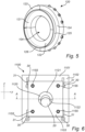
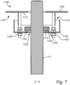
- FIGS. 6-7 illustrate a sealing arrangement 1100 according to a second example of the disclosure. Similar to the first example, the sealing arrangement 1100 comprises an annular first sealing device 1120 configured to be sealingly attached to the shaft 20 around a perimeter 21 of the shaft 20. The sealing arrangement 1100 further comprises a second sealing device 1101, comprising a base part 1102 configured to be sealingly attached to the chamber wall 2 around the opening 10. A proximal wall 1113 of the base part 1102 abuts the chamber wall 2. The second sealing device 1101 further comprises an adjustment part 1103 defining a first aperture 1104 for receiving the shaft 20.
- the adjustment part 1103 is adjustable relative to the base part 1102 to enable adjustment of a position of the first aperture 1104 relative to the opening 10 in the chamber wall 2 when the base part 1102 is attached to the chamber wall 2.
- the first sealing device 1120 and the second sealing device 1101 are together configured to form an annular seal 1150 extending around the first aperture 1104.
- the first sealing device 1120 is configured to be disposed between the base part 1102 and the adjustment part 1103, and the annular seal 1150 is configured to be formed between a proximal surface 1110 of the adjustment part 1103 and a distal surface 1126 of the first sealing device 1120.
- the adjustment part 1103 is in the second example configured to be attached to the base part 1102 by fasteners 1155. At least some of the fasteners 1155, such as all fasteners 1155, are configured to enable adjustment of a distance between the proximal wall 1113 of the base part 1102 and the adjustment part 1103. A tilting of the adjustment part 1103 relative to the base part 1102 may thereby be achieved, such that a position of the first aperture 1104 relative to the opening 10 in the chamber wall 2 may be varied.
- a column 1115 configured to be filled with an insulating material is formed between the base part 1102 and the adjustment part 1103, reducing heat losses.
- the first sealing device 1120 may be formed from several releasably joinable parts, such as at least two parts 1121, 1122 configured to be located on opposite sides of the shaft 20.
- the second sealing device 1101 may also be formed from several releasably joinable parts, such as at least two parts located on opposite sides of the shaft 20.
- the base part 102, 1102 is configured to be attached to the chamber wall 2 by fastening devices 30, such as screws or bolts.
- the fastening devices 30 may be configured to enable adjustment of the base part 1102 relative to the chamber wall 2 along a direction parallel with the chamber wall 2. In the illustrated second example, this is achieved by elongated slots 31 extending along the z-axis, through which the fastening devices 30 extend.
- the shaft 20 may in both examples be configured to extend through the opening 10 at a shaft angle ⁇ (see FIG. 4 ) defined relative to a normal direction of the chamber wall 2, corresponding to the x-axis.
- the adjustment part 103, 1103 is configured to enable adjustment of the position of the first aperture 104, 1104 relative to the opening 10 to receive the shaft 20 extending through the opening 10 and the first aperture 104, 1104 at a shaft angle ⁇ within a predefined non-zero range of shaft angles.
- the adjustment part 103, 1103 is tiltable relative to the base part 102 about at least one axis A1 parallel to the chamber wall 2.
- the configuration of the adjustment part 103 and the pocket 115 enables the range to include all shaft angles ⁇ having a magnitude of up to about 7°, since the adjustment part 103 can be moved to any position within the pocket 115 and is not limited to tilting about a specific axis.
- the configuration of the second sealing device 101 such that the adjustment part is only tiltable relative to the base part to accommodate shaft angles lying within the xz-plane, it may be possible to enable tilting to shaft angles having a magnitude of up to 10°, or even up to 15°.
- the configuration is less flexible and tilting of the adjustment part 1103 may typically be possible about the y-axis and/or about the z-axis by adjusting the length of the fasteners 1155.
- Shaft angles having a magnitude of up to 5°, or up to 10°, or even up to 15° may be accommodated, provided that the shaft 20 is tilted within the xz-plane.
- sealing arrangement 100 is in the illustrated examples mounted to an external side of the chamber wall 2, it may in other examples be mounted to an internal side thereof, i.e., within the chamber 1. However, mounting to the external side may be preferred due to easier assembly and adjustment.
- Example 1 A sealing arrangement (100, 1100) for reducing leakage of gas via an opening (10) formed in a chamber wall (2) of a chamber (1) in connection with rotation of a shaft (20) extending through the opening (10), the sealing arrangement (100, 1100) comprising:
- Example 2 The sealing arrangement of example 1, wherein the shaft (20) is configured to extend through the opening (10) at a shaft angle ( ⁇ ) defined relative to a normal direction of the chamber wall (2), and wherein the adjustment part (103, 1103) is configured to enable adjustment of the position of the first aperture (104, 1104) relative to the opening (10) to receive the shaft (20) extending through the opening (10) and the first aperture (104, 1104) at any shaft angle ( ⁇ ) within a predefined non-zero range of shaft angles.
- Example 3 The sealing arrangement of example 2, wherein the predefined non-zero range of shaft angles includes at least shaft angles having a magnitude of up to 5°, preferably shaft angles having a magnitude of up to 10°, more preferably shaft angles having a magnitude of up to 15°.
- Example 4 The sealing device of any one of the preceding examples, wherein the annular seal (150, 1150) is formed by a first sealing surface (126, 1126) of the first sealing device (120) and a second sealing surface (110a, 1110) of the adjustment part (103, 1103).
- Example 5 The sealing arrangement of any one of the preceding examples, wherein the adjustment part (103, 1103) is configured to be tiltable relative to the base part (102, 1102) about at least a first axis (A1), the first axis (A1) being parallel to the chamber wall (2).
- Example 6 The sealing arrangement of any one of the preceding examples, wherein the first sealing device (120, 1120) and the second sealing device (101, 1101) are configured to be mounted to the shaft (20) and the chamber wall (2), respectively, when the shaft (20) extends through the opening (10).
- Example 7 The sealing arrangement of any one of the preceding examples, wherein the first sealing device (120, 1120) comprises at least two releasably joinable first parts (121, 122; 1121, 1122) configured to be disposed on opposing portions of the perimeter (21) of the shaft.
- Example 8 The sealing arrangement of example 7, wherein the at least two releasably joinable first parts (121, 122) together form an inner ring, and wherein the first sealing device (120) further comprises at least two releasably joinable second parts (123, 124) together forming an outer ring, and a sealing flange (125) clamped between the inner ring and the outer ring.
- Example 9 The sealing arrangement of example 8, wherein the sealing flange (125) is made of a pliable material.
- Example 10 The sealing arrangement of any one of the preceding examples, wherein the base part (102, 1102) comprises at least two releasably joinable parts (111, 112) configured to be disposed on mutually opposite sides of the shaft (20) extending through the opening (10), and wherein the adjustment part (103, 1103) comprises at least two releasably joinable parts (105, 106) configured to be disposed on mutually opposite sides of the shaft (20) extending through the opening (10).
- Example 11 The sealing arrangement of any one of the preceding examples, wherein the base part (102) comprises a proximal wall (113) configured to abut the chamber wall (2), and a distal wall (114) formed at a distance from the proximal wall (113) as measured in a direction normal to the proximal wall (113), a second aperture (116) configured to overlap with the opening (10) of the chamber wall (2) being formed in the proximal wall (113) and a third aperture configured to overlap with the opening (10) of the chamber wall (2) being formed in the distal wall (114), and wherein the distal wall (114) comprises an annular pocket (115) extending around an edge (117) of the third aperture, the pocket (115) being configured to slidingly receive the adjustment part (103).
- the base part (102) comprises a proximal wall (113) configured to abut the chamber wall (2), and a distal wall (114) formed at a distance from the proximal wall (113) as measured in a direction normal to the prox
- Example 12 The sealing arrangement of example 11, wherein the distal wall (114) and the adjustment part (103) together form a dome shape with a convexly rounded distal side (110) facing away from the proximal wall (113).
- Example 13 The sealing arrangement of example 12, wherein the first sealing device (120) comprises a sealing surface (126) configured to face a surface portion (110a) of the convexly rounded distal side (110) provided on the adjustment part (103).
- Example 14 The sealing arrangement of any one of examples 11-13, wherein the base part (102) comprises at least one proximal part (102a) comprising the proximal wall (113), and at least one removable distal part (102b), the annular pocket (115) being formed between the proximal and distal parts (102a, 102b).
- Example 15 The sealing arrangement of any one of the preceding examples, wherein the adjustment part (103) comprises a sheet formed as a portion of a spherical shell.
- Example 16 The sealing arrangement of any one of examples 1-10, wherein the adjustment part (1103) is configured to be attached to the base part (1102) by fasteners (1155), wherein at least some of the fasteners (1155) are configured to enable adjustment of a distance between the base part (1102) and the adjustment part (1103).
- Example 17 The sealing arrangement of example 16, wherein a column (1115) configured to be filled with an insulating material is formed between the base part (1102) and the adjustment part (1103).
- Example 18 The sealing arrangement of example 17, wherein the first sealing device (1120) is configured to be disposed between the base part (1102) and the adjustment part (1103), and wherein the annular seal (1150) is configured to be formed between a proximal surface (1110) of the adjustment part (1103) and a distal surface (1126) of the first sealing device (1120).
- Example 19 The sealing arrangement of any one of the preceding examples, wherein the base part (102, 1102) is configured to be attached to the chamber wall (2) by fastening devices (30) configured to enable adjustment of the base part (102, 1102) relative to the chamber wall (2) along at least one direction parallel with the chamber wall (2).
- Example 20 A climate chamber (1) for testing of vehicle components, comprising the sealing arrangement (100, 1100) of any one of the preceding examples.
- Relative terms such as “below” or “above” or “upper” or “lower” or “horizontal” or “vertical” may be used herein to describe a relationship of one element to another element as illustrated in the Figures. It will be understood that these terms and those discussed above are intended to encompass different orientations of the device in addition to the orientation depicted in the Figures. It will be understood that when an element is referred to as being “connected” or “coupled” to another element, it can be directly connected or coupled to the other element, or intervening elements may be present. In contrast, when an element is referred to as being “directly connected” or “directly coupled” to another element, there are no intervening elements present.
Landscapes
- Engineering & Computer Science (AREA)
- General Engineering & Computer Science (AREA)
- Mechanical Engineering (AREA)
- Physics & Mathematics (AREA)
- General Physics & Mathematics (AREA)
- Sealing Devices (AREA)
- Gasket Seals (AREA)
Abstract
an annular first sealing device (120) configured to be sealingly attached around the shaft,
a second sealing device comprising a base part (102) configured to be sealingly attached to the chamber wall around the opening, and an adjustment part (103) defining an aperture (104) for receiving the shaft, the adjustment part being adjustable relative to the base part to enable adjustment of a position of the first aperture relative to the opening (10) when the base part is attached to the wall, thereby adapting the sealing arrangement to different shaft angles,
wherein the first and second sealing devices are together configured to form an annular seal (150) extending around the aperture.
Description
- The disclosure relates generally to climate chambers used for testing of vehicle equipment including rotating components, such as transmissions, motors, etc. In particular aspects, the disclosure relates to a sealing arrangement and a climate chamber. The disclosure can be applied in the testing of equipment for heavy-duty vehicles, such as trucks, buses, and construction equipment, among other vehicle types.
- In testing of vehicle equipment comprising rotating components, such as transmissions, it is common to use a climate chamber in which the temperature can be varied and in which the vehicle equipment to be tested is placed. Usually, a motor or engine driving the vehicle equipment via a rotating shaft is positioned outside of the chamber. This requires that the climate chamber has an opening through which the rotating shaft may extend. A temperature difference between the climate chamber and a room in which it is located may be large, since it is desirable that the temperature within the climate chamber can be set to temperatures corresponding to extreme weather conditions. Leakage of air via the opening may therefore lead to substantial energy losses as well as difficulties to control the temperature within the climate chamber.
- According to a first aspect of the disclosure, a sealing arrangement for reducing leakage of gas via an opening formed in a chamber wall of a chamber in connection with rotation of a shaft extending through the opening, the sealing arrangement comprising:
- an annular first sealing device configured to be sealingly attached to the shaft around a perimeter of the shaft,
- a second sealing device comprising a base part configured to be sealingly attached to the chamber wall around the opening, and an adjustment part defining a first aperture for receiving the shaft, the adjustment part being adjustable relative to the base part to enable adjustment of a position of the first aperture relative to the opening in the chamber wall when the base part is attached to the chamber wall,
- wherein the first sealing device and the second sealing device are together configured to form an annular seal extending around the first aperture.
- The first aspect of the disclosure may seek to provide an in at least some aspect improved sealing arrangement for a climate chamber. A technical benefit may include the possibility to accommodate the rotating shaft at different shaft angles, thanks to the possibility to adjust the position of the first aperture relative to the opening. A reduced leakage of gas, and thereby temperature, via the opening may thereby be achieved.
- Optionally in some examples, including in at least one preferred example, the shaft is configured to extend through the opening at a shaft angle defined relative to a normal direction of the chamber wall, and the adjustment part is configured to enable adjustment of the position of the first aperture relative to the opening to receive the shaft extending through the opening and the first aperture at any shaft angle within a predefined non-zero range of shaft angles. A technical benefit may include accommodating varying shaft angles, which improves adaptability and reduces leakage of gas via the sealing arrangement.
- Optionally in some examples, including in at least one preferred example, the predefined non-zero range of shaft angles includes at least shaft angles having a magnitude of up to 5°, preferably shaft angles having a magnitude of up to 10°, more preferably shaft angles having a magnitude of up to 15°. In at least one preferred example, the predefined non-zero range of shaft angles includes shaft angles having a magnitude of up to 7°. A technical benefit may include a sufficient versatility of the sealing arrangement for different operational configurations.
- Optionally in some examples, including in at least one preferred example, the annular seal is formed by a first sealing surface of the first sealing device and a second sealing surface of the adjustment part. A technical benefit may include improved sealing efficiency by ensuring close contact between the sealing surfaces when the position of the first aperture is altered.
- Optionally in some examples, including in at least one preferred example, the adjustment part is configured to be tiltable relative to the base part about at least a first axis, the first axis being parallel to the chamber wall. A technical benefit may include the ability to accommodate various shaft angles.
- Optionally in some examples, including in at least one preferred example, the first sealing device and the second sealing device are configured to be mounted to the shaft and the chamber wall, respectively, when the shaft extends through the opening. A technical benefit may include simplified assembly and maintenance processes.
- Optionally in some examples, including in at least one preferred example, the first sealing device comprises at least two releasably joinable first parts configured to be disposed on opposing portions of the perimeter of the shaft. A technical benefit may include easier installation and removal of the sealing device without disassembling the shaft.
- Optionally in some examples, including in at least one preferred example, the at least two releasably joinable first parts together form an inner ring, wherein the first sealing device further comprises at least two releasably joinable second parts together forming an outer ring, and a sealing flange clamped between the inner ring and the outer ring. A technical benefit may include enhanced sealing performance by securely retaining the sealing flange.
- Optionally in some examples, including in at least one preferred example, the sealing flange is made of a pliable material. A technical benefit may include improved conformity to irregular surfaces, enhancing sealing efficiency.
- Optionally in some examples, including in at least one preferred example, the base part comprises at least two releasably joinable parts configured to be disposed on mutually opposite sides of the shaft extending through the opening, and the adjustment part comprises at least two releasably joinable parts configured to be disposed on mutually opposite sides of the shaft extending through the opening. A technical benefit may include easier installation and removal of the sealing device without disassembling the shaft.
- Optionally in some examples, including in at least one preferred example, the base part comprises a proximal wall configured to abut the chamber wall, and a distal wall formed at a distance from the proximal wall as measured in a direction normal to the proximal wall, a second aperture configured to overlap with the opening of the chamber wall being formed in the proximal wall and a third aperture configured to overlap with the opening of the chamber wall being formed in the distal wall, wherein the distal wall comprises an annular pocket extending around an edge of the third aperture, the pocket being configured to slidingly receive the adjustment part. The position of the first aperture may thereby be varied by sliding the adjustment member to a desired position within the annular pocket. A technical benefit may include enhanced adjustability and sealing integrity.
- Optionally in some examples, including in at least one preferred example, the distal wall and the adjustment part together form a dome shape with a convexly rounded distal side facing away from the proximal wall. A technical benefit may include enhanced adjustability.
- Optionally in some examples, including in at least one preferred example, the first sealing device comprises a sealing surface configured to face a surface portion of the convexly rounded distal side provided on the adjustment part. A technical benefit may include facilitated adjustment of the seal between the first and second sealing devices by adjusting a position of the first sealing device.
- Optionally in some examples, including in at least one preferred example, the base part comprises at least one proximal part comprising the proximal wall, and at least one removable distal part, the annular pocket being formed between the proximal and distal parts. A technical benefit may include modular construction, facilitating replacement and customization.
- Optionally in some examples, including in at least one preferred example, the adjustment part comprises a sheet formed as a portion of a spherical shell. A technical benefit may include improved adjustability for various shaft angles.
- Optionally in some examples, including in at least one preferred example, the adjustment part is configured to be attached to the base part by fasteners, wherein at least some of the fasteners are configured to enable adjustment of a distance between the base part and the adjustment part. A technical benefit may include that a tilting of the adjustment part relative to the base part may be achieved, such that a position of the first aperture relative to the opening in the chamber wall may be varied.
- Optionally in some examples, including in at least one preferred example, a column configured to be filled with an insulating material is formed between the base part and the adjustment part. A technical benefit may include enhanced thermal insulation, reducing heat transfer between the chamber interior and exterior.
- Optionally in some examples, including in at least one preferred example, the first sealing device is configured to be disposed between the base part and the adjustment part, and the annular seal is configured to be formed between a proximal surface of the adjustment part and a distal surface of the first sealing device. A technical benefit may include efficient sealing.
- Optionally in some examples, including in at least one preferred example, the base part is configured to be attached to the chamber wall by fastening devices configured to enable adjustment of the base part relative to the chamber wall along at least one direction parallel with the chamber wall. A technical benefit may include enhanced adjustability of the position of the first aperture relative to the opening.
- According to a second aspect of the disclosure, a climate chamber for testing of vehicle components, comprising the sealing arrangement of the first aspect is provided. The second aspect of the disclosure may seek to provide an in at least some aspect improved climate chamber. A technical benefit may include a climate chamber which is able to accommodate rotating shafts at various shaft angles, with relatively small leakage of gas via the opening. Thanks to the possibility to vary the shaft angle, a more compact arrangement may be provided, suitable for testing of equipment for heavy-duty vehicles.
- The disclosed aspects, examples (including any preferred examples), and/or accompanying claims may be suitably combined with each other as would be apparent to anyone of ordinary skill in the art. Additional features and advantages are disclosed in the following description, claims, and drawings, and in part will be readily apparent therefrom to those skilled in the art or recognized by practicing the disclosure as described herein.
- Examples are described in more detail below with reference to the appended drawings.
-
FIG. 1 is an exemplary climate chamber according to an example. -
FIG. 2 is a sectional view of an exemplary sealing arrangement according to a first example. -
FIG. 3 is a front end view of parts of the sealing arrangement according to the first example. -
FIG. 4 is a side view of parts of the sealing arrangement according to the first example. -
FIG. 5 is a perspective view of parts of the sealing arrangement according to the first example. -
FIG. 6 is a front end view of an exemplary sealing arrangement according to a second example. -
FIG. 7 is a sectional view of the sealing arrangement according to the second example along the line A-A inFIG. 6 . - The drawings are schematic and are not necessarily drawn to scale. Like reference numbers refer to like elements, unless expressed otherwise.
- The detailed description set forth below provides information and examples of the disclosed technology with sufficient detail to enable those skilled in the art to practice the disclosure.
-
FIG. 1 is anexemplary climate chamber 1 for testing of vehicle components according to an example. The vehicle components to be tested may be any type of components whose behavior in different temperatures needs to be tested, such as components of a powertrain, e.g., a transmission, a differential, a motor, an engine, etc. In particular, theclimate chamber 1 is suitable for the testing of rotating components driven by an engine or electric motor positioned outside of theclimate chamber 1 via ashaft 20 extending through anopening 10 provided in achamber wall 2. A temperature difference between theclimate chamber 1 and a room in which it is located may be large, since it is desirable that the temperature within theclimate chamber 1 can be set to temperatures corresponding to extreme weather conditions. Leakage of air via theopening 10 may therefore lead to substantial energy losses as well as difficulties to control the temperature within theclimate chamber 1. - A sealing
arrangement 100 is arranged to provide a seal between theshaft 20 and thechamber wall 2 and thereby reduce the leakage of gas, such as air, via theopening 10. In the illustrated example, thechamber wall 2 extends in a yz-plane and theshaft 20 extends along an x-axis, normal to the yz-plane. However, it is desirable to be able to change the direction of extension of theshaft 20, such that it can extend at an angle with respect to the x-axis. Theshaft 20 may, for example, be a propeller shaft whose angle of extension may be varied to adapt to different powertrain configurations. For this purpose, the proposedsealing arrangement 100 is arranged such that it can be adjusted to accommodate a range of different shaft angles. -
FIG. 2 illustrates the sealingarrangement 100 according to a first example of the disclosure, arranged to form a seal between apropeller shaft 20 and achamber wall 2, wherein theshaft 20 extends at a non-zero shaft angle through an opening in thechamber wall 2. The sealingarrangement 100 comprises an annularfirst sealing device 120 configured to be sealingly attached to theshaft 20 around aperimeter 21 of theshaft 20. It further comprises asecond sealing device 101, comprising abase part 102 configured to be sealingly attached to thechamber wall 2 around theopening 10. Aproximal wall 113 of thebase part 102 abuts thechamber wall 2 and extends in parallel with thechamber wall 2. Thesecond sealing device 101 further comprises anadjustment part 103 defining a first aperture for receiving theshaft 20. Theadjustment part 103 is adjustable relative to thebase part 102 to enable adjustment of a position of the first aperture relative to theopening 10 in thechamber wall 2 when thebase part 102 is attached to thechamber wall 2. Thefirst sealing device 120 and thesecond sealing device 101 are together configured to form anannular seal 150 extending around the first aperture. In the illustrated first example, thefirst sealing device 120 is in contact with theadjustment part 103, which is in the form of a sheet formed as a portion of a spherical shell. Theadjustment part 103 is slidable within anannular pocket 115 formed in adistal wall 114 of thebase part 102, thepocket 115 having a shape adapted to receive theadjustment part 103, such that the position of the first aperture through which theshaft 20 extends can be adjusted. Thedistal wall 114 is formed at a distance from theproximal wall 113, as measured in a direction normal to theproximal wall 113. The sizes of theadjustment part 103 and thepocket 115 are adapted such that an entire peripheral edge of theadjustment part 103 is always contained within thepocket 115. Hence, theadjustment part 103 can in the illustrated first embodiment be moved relative to thebase part 102 to accommodate ashaft 20 extending in any direction within a predefined range of shaft angles delimited by the design of thesecond sealing device 101. -
FIGS. 3-4 illustrate thesecond sealing device 101 in further detail. Thebase part 102 may be formed from several parts. As best seen inFIG. 3 , thebase part 102 may comprise two releasablyjoinable parts shaft 20 extending through theopening 10 in thechamber wall 2. The two releasablyjoinable parts adjustment part 103 may also comprise at least two releasablyjoinable parts shaft 20 extending through theopening 10. InFIG. 3 , the dashed line corresponds to the peripheral edge of theadjustment part 103. A circularfirst aperture 104 for receiving theshaft 20 is formed when the releasablyjoinable parts second sealing device 101 may be assembled in connection with mounting on thechamber wall 2, such that it can be mounted to thechamber wall 2 when theshaft 20 already extends through theopening 10. - The
base part 102 may comprise more than two separate parts. As illustrated inFIG. 4 , thebase part 102 may comprise at least one proximal part 102a, comprising theproximal wall 113 configured to abut the chamber wall 2 (seeFIG. 2 ), and at least one removable distal part 102b. The annular pocket 115 (seeFIG. 2 ) may be formed between the proximal and distal parts 102a, 102b. In this way, theadjustment part 103 may be mounted after the proximal part 102a, whereafter the distal part 102b is attached to the proximal part 102a by fasteners, screw fitting, adhesive, or any other type of attachment means. To enable mounting of thebase part 102 around theshaft 20 as described above, two releasable proximal parts 102a and two releasable distal parts 102b may be provided. InFIG. 4 , only one of the distal parts 102b is illustrated. - A
second aperture 116 is formed in theproximal wall 113 of thebase part 102, and a third aperture delimited by anedge 117 is formed in thedistal wall 114. Both the second and third apertures are configured to overlap with theopening 10 of thechamber wall 2 such that theshaft 20 may extend through thebase part 102. - The
distal wall 114 and theadjustment part 103 together form a dome shape with a convexly roundeddistal side 110 facing away from theproximal wall 113. Thedistal side 110 comprises a convexly roundedsurface portion 110a provided on theadjustment part 103. Thesurface portion 110a is configured to form theannular seal 150 together with thefirst sealing device 120 and constitutes asecond sealing surface 110a of the sealingarrangement 100. -
FIG. 5 illustrates thefirst sealing device 120 used in thesealing arrangement 100 according to the first example in greater detail. Thefirst sealing device 120 comprises afirst sealing surface 126 configured to face the convexly roundedsurface portion 110a of theadjustment part 103. It is not necessary that thefirst sealing surface 126 and thesecond sealing surface 110a (refer toFig. 4 ) are in contact during use, although the sealing integrity will be improved if they are. However, since the shaft 20 (as shown inFig. 2 ) and thereby also thefirst sealing device 120 will rotate with respect to the second sealing device 101 (as shown inFig. 2 ), friction will be generated when the surfaces are in contact. Hence, an optimal position of thefirst sealing device 120 relative to thesecond sealing device 101 may be found by taking friction losses as well as energy losses due to gas leakage via theannular seal 150 into account. Lubrication may be used if the surfaces are in contact. - The
first sealing device 120 comprises at least two releasably joinablefirst parts perimeter 21 of the shaft 20 (as shown inFig. 2 ), i.e., on opposite sides of theshaft 20. Thesefirst parts first sealing device 120 further comprises at least two releasably joinablesecond parts flange 125 clamped between the inner ring and the outer ring. The sealingflange 125 may preferably be made of a pliable material, such as a soft rubber material or similar. Hence, similar to thesecond sealing device 101, thefirst sealing device 120 is made of several parts that can be assembled around theshaft 20 when theshaft 20 already extends through theopening 10. -
FIGS. 6-7 illustrate asealing arrangement 1100 according to a second example of the disclosure. Similar to the first example, thesealing arrangement 1100 comprises an annularfirst sealing device 1120 configured to be sealingly attached to theshaft 20 around aperimeter 21 of theshaft 20. Thesealing arrangement 1100 further comprises asecond sealing device 1101, comprising abase part 1102 configured to be sealingly attached to thechamber wall 2 around theopening 10. Aproximal wall 1113 of thebase part 1102 abuts thechamber wall 2. Thesecond sealing device 1101 further comprises anadjustment part 1103 defining afirst aperture 1104 for receiving theshaft 20. Theadjustment part 1103 is adjustable relative to thebase part 1102 to enable adjustment of a position of thefirst aperture 1104 relative to theopening 10 in thechamber wall 2 when thebase part 1102 is attached to thechamber wall 2. Thefirst sealing device 1120 and thesecond sealing device 1101 are together configured to form anannular seal 1150 extending around thefirst aperture 1104. In the illustrated second example, thefirst sealing device 1120 is configured to be disposed between thebase part 1102 and theadjustment part 1103, and theannular seal 1150 is configured to be formed between aproximal surface 1110 of theadjustment part 1103 and adistal surface 1126 of thefirst sealing device 1120. - The
adjustment part 1103 is in the second example configured to be attached to thebase part 1102 byfasteners 1155. At least some of thefasteners 1155, such as allfasteners 1155, are configured to enable adjustment of a distance between theproximal wall 1113 of thebase part 1102 and theadjustment part 1103. A tilting of theadjustment part 1103 relative to thebase part 1102 may thereby be achieved, such that a position of thefirst aperture 1104 relative to theopening 10 in thechamber wall 2 may be varied. A column 1115 configured to be filled with an insulating material is formed between thebase part 1102 and theadjustment part 1103, reducing heat losses. - Similar to the first example, the
first sealing device 1120 may be formed from several releasably joinable parts, such as at least twoparts shaft 20. Thesecond sealing device 1101 may also be formed from several releasably joinable parts, such as at least two parts located on opposite sides of theshaft 20. - In both illustrated examples, the
base part chamber wall 2 byfastening devices 30, such as screws or bolts. As illustrated in the second example, thefastening devices 30 may be configured to enable adjustment of thebase part 1102 relative to thechamber wall 2 along a direction parallel with thechamber wall 2. In the illustrated second example, this is achieved byelongated slots 31 extending along the z-axis, through which thefastening devices 30 extend. - The
shaft 20 may in both examples be configured to extend through theopening 10 at a shaft angle α (seeFIG. 4 ) defined relative to a normal direction of thechamber wall 2, corresponding to the x-axis. Theadjustment part first aperture opening 10 to receive theshaft 20 extending through theopening 10 and thefirst aperture adjustment part base part 102 about at least one axis A1 parallel to thechamber wall 2. In the first example, the configuration of theadjustment part 103 and thepocket 115 enables the range to include all shaft angles α having a magnitude of up to about 7°, since theadjustment part 103 can be moved to any position within thepocket 115 and is not limited to tilting about a specific axis. By adjusting the configuration of thesecond sealing device 101 such that the adjustment part is only tiltable relative to the base part to accommodate shaft angles lying within the xz-plane, it may be possible to enable tilting to shaft angles having a magnitude of up to 10°, or even up to 15°. - In the second example, the configuration is less flexible and tilting of the
adjustment part 1103 may typically be possible about the y-axis and/or about the z-axis by adjusting the length of thefasteners 1155. Shaft angles having a magnitude of up to 5°, or up to 10°, or even up to 15° may be accommodated, provided that theshaft 20 is tilted within the xz-plane. - Although the sealing
arrangement 100 is in the illustrated examples mounted to an external side of thechamber wall 2, it may in other examples be mounted to an internal side thereof, i.e., within thechamber 1. However, mounting to the external side may be preferred due to easier assembly and adjustment. - In the following, a list of numbered examples of the disclosure is presented.
- Example 1: A sealing arrangement (100, 1100) for reducing leakage of gas via an opening (10) formed in a chamber wall (2) of a chamber (1) in connection with rotation of a shaft (20) extending through the opening (10), the sealing arrangement (100, 1100) comprising:
- an annular first sealing device (120, 1120) configured to be sealingly attached to the shaft (20) around a perimeter (21) of the shaft (20),
- a second sealing device (101, 1101) comprising a base part (102, 1102) configured to be sealingly attached to the chamber wall (2) around the opening (10), and an adjustment part (103, 1103) defining a first aperture (104, 1104) for receiving the shaft (20), the adjustment part (103, 1103) being adjustable relative to the base part (102, 1102) to enable adjustment of a position of the first aperture (104, 1104) relative to the opening (10) in the chamber wall (2) when the base part (102, 1102) is attached to the chamber wall (2),
- wherein the first sealing device (120, 1120) and the second sealing device (101, 1101) are together configured to form an annular seal (150, 1150) extending around the first aperture (104, 1104).
- Example 2: The sealing arrangement of example 1, wherein the shaft (20) is configured to extend through the opening (10) at a shaft angle (α) defined relative to a normal direction of the chamber wall (2), and wherein the adjustment part (103, 1103) is configured to enable adjustment of the position of the first aperture (104, 1104) relative to the opening (10) to receive the shaft (20) extending through the opening (10) and the first aperture (104, 1104) at any shaft angle (α) within a predefined non-zero range of shaft angles.
- Example 3. The sealing arrangement of example 2, wherein the predefined non-zero range of shaft angles includes at least shaft angles having a magnitude of up to 5°, preferably shaft angles having a magnitude of up to 10°, more preferably shaft angles having a magnitude of up to 15°.
- Example 4. The sealing device of any one of the preceding examples, wherein the annular seal (150, 1150) is formed by a first sealing surface (126, 1126) of the first sealing device (120) and a second sealing surface (110a, 1110) of the adjustment part (103, 1103).
- Example 5. The sealing arrangement of any one of the preceding examples, wherein the adjustment part (103, 1103) is configured to be tiltable relative to the base part (102, 1102) about at least a first axis (A1), the first axis (A1) being parallel to the chamber wall (2).
- Example 6. The sealing arrangement of any one of the preceding examples, wherein the first sealing device (120, 1120) and the second sealing device (101, 1101) are configured to be mounted to the shaft (20) and the chamber wall (2), respectively, when the shaft (20) extends through the opening (10).
- Example 7. The sealing arrangement of any one of the preceding examples, wherein the first sealing device (120, 1120) comprises at least two releasably joinable first parts (121, 122; 1121, 1122) configured to be disposed on opposing portions of the perimeter (21) of the shaft.
- Example 8. The sealing arrangement of example 7, wherein the at least two releasably joinable first parts (121, 122) together form an inner ring, and wherein the first sealing device (120) further comprises at least two releasably joinable second parts (123, 124) together forming an outer ring, and a sealing flange (125) clamped between the inner ring and the outer ring.
- Example 9. The sealing arrangement of example 8, wherein the sealing flange (125) is made of a pliable material.
- Example 10. The sealing arrangement of any one of the preceding examples, wherein the base part (102, 1102) comprises at least two releasably joinable parts (111, 112) configured to be disposed on mutually opposite sides of the shaft (20) extending through the opening (10), and wherein the adjustment part (103, 1103) comprises at least two releasably joinable parts (105, 106) configured to be disposed on mutually opposite sides of the shaft (20) extending through the opening (10).
- Example 11. The sealing arrangement of any one of the preceding examples, wherein the base part (102) comprises a proximal wall (113) configured to abut the chamber wall (2), and a distal wall (114) formed at a distance from the proximal wall (113) as measured in a direction normal to the proximal wall (113), a second aperture (116) configured to overlap with the opening (10) of the chamber wall (2) being formed in the proximal wall (113) and a third aperture configured to overlap with the opening (10) of the chamber wall (2) being formed in the distal wall (114), and wherein the distal wall (114) comprises an annular pocket (115) extending around an edge (117) of the third aperture, the pocket (115) being configured to slidingly receive the adjustment part (103).
- Example 12. The sealing arrangement of example 11, wherein the distal wall (114) and the adjustment part (103) together form a dome shape with a convexly rounded distal side (110) facing away from the proximal wall (113).
- Example 13. The sealing arrangement of example 12, wherein the first sealing device (120) comprises a sealing surface (126) configured to face a surface portion (110a) of the convexly rounded distal side (110) provided on the adjustment part (103).
- Example 14. The sealing arrangement of any one of examples 11-13, wherein the base part (102) comprises at least one proximal part (102a) comprising the proximal wall (113), and at least one removable distal part (102b), the annular pocket (115) being formed between the proximal and distal parts (102a, 102b).
- Example 15. The sealing arrangement of any one of the preceding examples, wherein the adjustment part (103) comprises a sheet formed as a portion of a spherical shell.
- Example 16. The sealing arrangement of any one of examples 1-10, wherein the adjustment part (1103) is configured to be attached to the base part (1102) by fasteners (1155), wherein at least some of the fasteners (1155) are configured to enable adjustment of a distance between the base part (1102) and the adjustment part (1103).
- Example 17. The sealing arrangement of example 16, wherein a column (1115) configured to be filled with an insulating material is formed between the base part (1102) and the adjustment part (1103).
- Example 18. The sealing arrangement of example 17, wherein the first sealing device (1120) is configured to be disposed between the base part (1102) and the adjustment part (1103), and wherein the annular seal (1150) is configured to be formed between a proximal surface (1110) of the adjustment part (1103) and a distal surface (1126) of the first sealing device (1120).
- Example 19. The sealing arrangement of any one of the preceding examples, wherein the base part (102, 1102) is configured to be attached to the chamber wall (2) by fastening devices (30) configured to enable adjustment of the base part (102, 1102) relative to the chamber wall (2) along at least one direction parallel with the chamber wall (2).
- Example 20. A climate chamber (1) for testing of vehicle components, comprising the sealing arrangement (100, 1100) of any one of the preceding examples.
- The terminology used herein is for the purpose of describing particular aspects only and is not intended to be limiting of the disclosure. As used herein, the singular forms "a," "an," and "the" are intended to include the plural forms as well, unless the context clearly indicates otherwise. As used herein, the term "and/or" includes any and all combinations of one or more of the associated listed items. It will be further understood that the terms "comprises," "comprising," "includes," and/or "including" when used herein specify the presence of stated features, integers, actions, steps, operations, elements, and/or components, but do not preclude the presence or addition of one or more other features, integers, actions, steps, operations, elements, components, and/or groups thereof.
- It will be understood that, although the terms first, second, etc., may be used herein to describe various elements, these elements should not be limited by these terms. These terms are only used to distinguish one element from another. For example, a first element could be termed a second element, and, similarly, a second element could be termed a first element without departing from the scope of the present disclosure.
- Relative terms such as "below" or "above" or "upper" or "lower" or "horizontal" or "vertical" may be used herein to describe a relationship of one element to another element as illustrated in the Figures. It will be understood that these terms and those discussed above are intended to encompass different orientations of the device in addition to the orientation depicted in the Figures. It will be understood that when an element is referred to as being "connected" or "coupled" to another element, it can be directly connected or coupled to the other element, or intervening elements may be present. In contrast, when an element is referred to as being "directly connected" or "directly coupled" to another element, there are no intervening elements present.
- Unless otherwise defined, all terms (including technical and scientific terms) used herein have the same meaning as commonly understood by one of ordinary skill in the art to which this disclosure belongs. It will be further understood that terms used herein should be interpreted as having a meaning consistent with their meaning in the context of this specification and the relevant art and will not be interpreted in an idealized or overly formal sense unless expressly so defined herein.
- It is to be understood that the present disclosure is not limited to the aspects described above and illustrated in the drawings; rather, the skilled person will recognize that many changes and modifications may be made within the scope of the present disclosure and appended claims. In the drawings and specification, there have been disclosed aspects for purposes of illustration only and not for purposes of limitation, the scope of the disclosure being set forth in the following claims.
Claims (15)
- A sealing arrangement (100, 1100) for reducing leakage of gas via an opening (10) formed in a chamber wall (2) of a chamber (1) in connection with rotation of a shaft (20) extending through the opening (10), the sealing arrangement (100, 1100) comprising:an annular first sealing device (120, 1120) configured to be sealingly attached to the shaft (20) around a perimeter (21) of the shaft (20),a second sealing device (101, 1101) comprising a base part (102, 1102) configured to be sealingly attached to the chamber wall (2) around the opening (10), and an adjustment part (103, 1103) defining a first aperture (104, 1104) for receiving the shaft (20), the adjustment part (103, 1103) being adjustable relative to the base part (102, 1102) to enable adjustment of a position of the first aperture (104, 1104) relative to the opening (10) in the chamber wall (2) when the base part (102, 1102) is attached to the chamber wall (2),wherein the first sealing device (120, 1120) and the second sealing device (101, 1101) are together configured to form an annular seal (150, 1150) extending around the first aperture (104, 1104).
- The sealing arrangement of claim 1, wherein the shaft (20) is configured to extend through the opening (10) at a shaft angle (α) defined relative to a normal direction of the chamber wall (2), and wherein the adjustment part (103, 1103) is configured to enable adjustment of the position of the first aperture (104, 1104) relative to the opening (10) to receive the shaft (20) extending through the opening (10) and the first aperture (104, 1104) at any shaft angle (α) within a predefined non-zero range of shaft angles.
- The sealing device of claim 1 or 2, wherein the annular seal (150, 1150) is formed by a first sealing surface (126, 1126) of the first sealing device (120) and a second sealing surface (110a, 1110) of the adjustment part (103, 1103).
- The sealing arrangement of any one of the preceding claims, wherein the adjustment part (103, 1103) is configured to be tiltable relative to the base part (102, 1102) about at least a first axis (A1), the first axis (A1) being parallel to the chamber wall (2).
- The sealing arrangement of any one of the preceding claims, wherein the first sealing device (120, 1120) and the second sealing device (101, 1101) are configured to be mounted to the shaft (20) and the chamber wall (2), respectively, when the shaft (20) extends through the opening (10).
- The sealing arrangement of any one of the preceding claims, wherein the first sealing device (120, 1120) comprises at least two releasably joinable first parts (121, 122; 1121, 1122) configured to be disposed on opposing portions of the perimeter (21) of the shaft.
- The sealing arrangement of claim 6, wherein the at least two releasably joinable first parts (121, 122) together form an inner ring, and wherein the first sealing device (120) further comprises at least two releasably joinable second parts (123, 124) together forming an outer ring, and a sealing flange (125) clamped between the inner ring and the outer ring.
- The sealing arrangement of any one of the preceding claims, wherein the base part (102, 1102) comprises at least two releasably joinable parts (111, 112) configured to be disposed on mutually opposite sides of the shaft (20) extending through the opening (10), and wherein the adjustment part (103, 1103) comprises at least two releasably joinable parts (105, 106) configured to be disposed on mutually opposite sides of the shaft (20) extending through the opening (10).
- The sealing arrangement of any one of the preceding claims, wherein the base part (102) comprises a proximal wall (113) configured to abut the chamber wall (2), and a distal wall (114) formed at a distance from the proximal wall (113) as measured in a direction normal to the proximal wall (113), a second aperture (116) configured to overlap with the opening (10) of the chamber wall (2) being formed in the proximal wall (113) and a third aperture configured to overlap with the opening (10) of the chamber wall (2) being formed in the distal wall (114), and wherein the distal wall (114) comprises an annular pocket (115) extending around an edge (117) of the third aperture, the pocket (115) being configured to slidingly receive the adjustment part (103).
- The sealing arrangement of claim 9, wherein the distal wall (114) and the adjustment part (103) together form a dome shape with a convexly rounded distal side (110) facing away from the proximal wall (113).
- The sealing arrangement of claim 10, wherein the first sealing device (120) comprises a sealing surface (126) configured to face a surface portion (110a) of the convexly rounded distal side (110) provided on the adjustment part (103).
- The sealing arrangement of any one of the preceding claims, wherein the adjustment part (103) comprises a sheet formed as a portion of a spherical shell.
- The sealing arrangement of any one of claims 1-8, wherein the adjustment part (1103) is configured to be attached to the base part (1102) by fasteners (1155), wherein at least some of the fasteners (1155) are configured to enable adjustment of a distance between the base part (1102) and the adjustment part (1103).
- The sealing arrangement of claim 14, wherein a column (1115) configured to be filled with an insulating material is formed between the base part (1102) and the adjustment part (1103).
- A climate chamber (1) for testing of vehicle components, comprising the sealing arrangement (100, 1100) of any one of the preceding claims.
Priority Applications (1)
| Application Number | Priority Date | Filing Date | Title |
|---|---|---|---|
| EP25150601.0A EP4545823A3 (en) | 2025-01-08 | 2025-01-08 | A sealing arrangement and a climate chamber |
Applications Claiming Priority (1)
| Application Number | Priority Date | Filing Date | Title |
|---|---|---|---|
| EP25150601.0A EP4545823A3 (en) | 2025-01-08 | 2025-01-08 | A sealing arrangement and a climate chamber |
Publications (2)
| Publication Number | Publication Date |
|---|---|
| EP4545823A2 true EP4545823A2 (en) | 2025-04-30 |
| EP4545823A3 EP4545823A3 (en) | 2025-07-30 |
Family
ID=94227597
Family Applications (1)
| Application Number | Title | Priority Date | Filing Date |
|---|---|---|---|
| EP25150601.0A Pending EP4545823A3 (en) | 2025-01-08 | 2025-01-08 | A sealing arrangement and a climate chamber |
Country Status (1)
| Country | Link |
|---|---|
| EP (1) | EP4545823A3 (en) |
Family Cites Families (6)
| Publication number | Priority date | Publication date | Assignee | Title |
|---|---|---|---|---|
| US1181143A (en) * | 1914-05-25 | 1916-05-02 | Herman C Korfhage | Stuffing-box. |
| GB1386602A (en) * | 1971-05-07 | 1975-03-12 | Gec Diesels Ltd | Shaft seal |
| US3971564A (en) * | 1974-05-24 | 1976-07-27 | Caterpillar Tractor Co. | Environmental seals for multidirectional control levers |
| US20020113375A1 (en) * | 2001-02-20 | 2002-08-22 | Gennady Ruderman | Pressure differential sealing device |
| CA2366693C (en) * | 2002-01-04 | 2004-07-27 | Keith D. Farquharson | Wellhead stuffing box support assembly |
| EP4147969B1 (en) * | 2021-09-13 | 2026-03-18 | Ratier-Figeac SAS | Control lever assembly for controlling an aircraft system |
-
2025
- 2025-01-08 EP EP25150601.0A patent/EP4545823A3/en active Pending
Also Published As
| Publication number | Publication date |
|---|---|
| EP4545823A3 (en) | 2025-07-30 |
Similar Documents
| Publication | Publication Date | Title |
|---|---|---|
| US7444729B2 (en) | Oil pan assembly and method of selecting an oil pan | |
| WO2004005830A8 (en) | Heat exchanger support device and associated heat exchanger module | |
| KR100944648B1 (en) | Fan attachment with dynamic out-of-balance equalization | |
| US5881857A (en) | Hydraulic fan coupling apparatus | |
| CN101248567A (en) | Element for positioning and retaining an electric motor stator in a compressor, compressor and method for mounting same | |
| EP1624196A2 (en) | Shroud and blower using the same | |
| CN110686908B (en) | Self-adaptive rotary opening and closing type automobile body air pressure balancing device for test | |
| EP0266098B1 (en) | Supercharger system noise reduction | |
| CN1302265A (en) | Adjustable steering clumn line for motor vehicle | |
| CN116576128B (en) | Cross-flow fans and indoor air conditioning units including the cross-flow fans | |
| CN113733903B (en) | Intermediate support assembly and vehicle | |
| CN210893697U (en) | A kind of self-adaptive rotary opening and closing body air pressure balance device for testing | |
| JP2000039209A (en) | Ceiling-mounted air conditioner | |
| JP3817925B2 (en) | Vehicle capacitors | |
| CA2260425A1 (en) | Air conditioner for a motor vehicle | |
| CN215635955U (en) | Inflatable multi-angle adjusting central control display screen | |
| AU2006201620B2 (en) | Steering shaft bearing assembly | |
| KR100375534B1 (en) | Dynamic damper | |
| CN222277274U (en) | Vibration reduction structure of transmission shafting and car | |
| JPH029330Y2 (en) | ||
| CN110925886A (en) | Air conditioner base and air conditioner | |
| EP0592417A1 (en) | Arrangement in valve dampers. | |
| US20030075406A1 (en) | Dynamic damper | |
| CN220152842U (en) | Indoor unit of air conditioner | |
| KR102758345B1 (en) | Shaft damper based on wireless power charging device and system for monitering using the same |
Legal Events
| Date | Code | Title | Description |
|---|---|---|---|
| PUAI | Public reference made under article 153(3) epc to a published international application that has entered the european phase |
Free format text: ORIGINAL CODE: 0009012 |
|
| STAA | Information on the status of an ep patent application or granted ep patent |
Free format text: STATUS: THE APPLICATION HAS BEEN PUBLISHED |
|
| AK | Designated contracting states |
Kind code of ref document: A2 Designated state(s): AL AT BE BG CH CY CZ DE DK EE ES FI FR GB GR HR HU IE IS IT LI LT LU LV MC ME MK MT NL NO PL PT RO RS SE SI SK SM TR |
|
| PUAL | Search report despatched |
Free format text: ORIGINAL CODE: 0009013 |
|
| AK | Designated contracting states |
Kind code of ref document: A3 Designated state(s): AL AT BE BG CH CY CZ DE DK EE ES FI FR GB GR HR HU IE IS IT LI LT LU LV MC ME MK MT NL NO PL PT RO RS SE SI SK SM TR |
|
| RIC1 | Information provided on ipc code assigned before grant |
Ipc: F16J 15/34 20060101AFI20250620BHEP Ipc: G01M 15/02 20060101ALI20250620BHEP |