EP4545818A1 - Radbremsanordnung - Google Patents
Radbremsanordnung Download PDFInfo
- Publication number
- EP4545818A1 EP4545818A1 EP23205887.5A EP23205887A EP4545818A1 EP 4545818 A1 EP4545818 A1 EP 4545818A1 EP 23205887 A EP23205887 A EP 23205887A EP 4545818 A1 EP4545818 A1 EP 4545818A1
- Authority
- EP
- European Patent Office
- Prior art keywords
- arrangement
- brake pad
- brake
- rod
- coil spring
- Prior art date
- Legal status (The legal status is an assumption and is not a legal conclusion. Google has not performed a legal analysis and makes no representation as to the accuracy of the status listed.)
- Pending
Links
Images


Classifications
-
- F—MECHANICAL ENGINEERING; LIGHTING; HEATING; WEAPONS; BLASTING
- F16—ENGINEERING ELEMENTS AND UNITS; GENERAL MEASURES FOR PRODUCING AND MAINTAINING EFFECTIVE FUNCTIONING OF MACHINES OR INSTALLATIONS; THERMAL INSULATION IN GENERAL
- F16D—COUPLINGS FOR TRANSMITTING ROTATION; CLUTCHES; BRAKES
- F16D55/00—Brakes with substantially-radial braking surfaces pressed together in axial direction, e.g. disc brakes
- F16D55/02—Brakes with substantially-radial braking surfaces pressed together in axial direction, e.g. disc brakes with axially-movable discs or pads pressed against axially-located rotating members
- F16D55/22—Brakes with substantially-radial braking surfaces pressed together in axial direction, e.g. disc brakes with axially-movable discs or pads pressed against axially-located rotating members by clamping an axially-located rotating disc between movable braking members, e.g. movable brake discs or brake pads
- F16D55/224—Brakes with substantially-radial braking surfaces pressed together in axial direction, e.g. disc brakes with axially-movable discs or pads pressed against axially-located rotating members by clamping an axially-located rotating disc between movable braking members, e.g. movable brake discs or brake pads with a common actuating member for the braking members
- F16D55/225—Brakes with substantially-radial braking surfaces pressed together in axial direction, e.g. disc brakes with axially-movable discs or pads pressed against axially-located rotating members by clamping an axially-located rotating disc between movable braking members, e.g. movable brake discs or brake pads with a common actuating member for the braking members the braking members being brake pads
- F16D55/226—Brakes with substantially-radial braking surfaces pressed together in axial direction, e.g. disc brakes with axially-movable discs or pads pressed against axially-located rotating members by clamping an axially-located rotating disc between movable braking members, e.g. movable brake discs or brake pads with a common actuating member for the braking members the braking members being brake pads in which the common actuating member is moved axially, e.g. floating caliper disc brakes
-
- F—MECHANICAL ENGINEERING; LIGHTING; HEATING; WEAPONS; BLASTING
- F16—ENGINEERING ELEMENTS AND UNITS; GENERAL MEASURES FOR PRODUCING AND MAINTAINING EFFECTIVE FUNCTIONING OF MACHINES OR INSTALLATIONS; THERMAL INSULATION IN GENERAL
- F16D—COUPLINGS FOR TRANSMITTING ROTATION; CLUTCHES; BRAKES
- F16D65/00—Parts or details
- F16D65/38—Slack adjusters
- F16D65/40—Slack adjusters mechanical
- F16D65/52—Slack adjusters mechanical self-acting in one direction for adjusting excessive play
- F16D65/54—Slack adjusters mechanical self-acting in one direction for adjusting excessive play by means of direct linear adjustment
-
- F—MECHANICAL ENGINEERING; LIGHTING; HEATING; WEAPONS; BLASTING
- F16—ENGINEERING ELEMENTS AND UNITS; GENERAL MEASURES FOR PRODUCING AND MAINTAINING EFFECTIVE FUNCTIONING OF MACHINES OR INSTALLATIONS; THERMAL INSULATION IN GENERAL
- F16D—COUPLINGS FOR TRANSMITTING ROTATION; CLUTCHES; BRAKES
- F16D55/00—Brakes with substantially-radial braking surfaces pressed together in axial direction, e.g. disc brakes
- F16D55/02—Brakes with substantially-radial braking surfaces pressed together in axial direction, e.g. disc brakes with axially-movable discs or pads pressed against axially-located rotating members
- F16D55/22—Brakes with substantially-radial braking surfaces pressed together in axial direction, e.g. disc brakes with axially-movable discs or pads pressed against axially-located rotating members by clamping an axially-located rotating disc between movable braking members, e.g. movable brake discs or brake pads
- F16D55/224—Brakes with substantially-radial braking surfaces pressed together in axial direction, e.g. disc brakes with axially-movable discs or pads pressed against axially-located rotating members by clamping an axially-located rotating disc between movable braking members, e.g. movable brake discs or brake pads with a common actuating member for the braking members
- F16D55/225—Brakes with substantially-radial braking surfaces pressed together in axial direction, e.g. disc brakes with axially-movable discs or pads pressed against axially-located rotating members by clamping an axially-located rotating disc between movable braking members, e.g. movable brake discs or brake pads with a common actuating member for the braking members the braking members being brake pads
-
- F—MECHANICAL ENGINEERING; LIGHTING; HEATING; WEAPONS; BLASTING
- F16—ENGINEERING ELEMENTS AND UNITS; GENERAL MEASURES FOR PRODUCING AND MAINTAINING EFFECTIVE FUNCTIONING OF MACHINES OR INSTALLATIONS; THERMAL INSULATION IN GENERAL
- F16D—COUPLINGS FOR TRANSMITTING ROTATION; CLUTCHES; BRAKES
- F16D65/00—Parts or details
- F16D65/02—Braking members; Mounting thereof
- F16D65/04—Bands, shoes or pads; Pivots or supporting members therefor
- F16D65/092—Bands, shoes or pads; Pivots or supporting members therefor for axially-engaging brakes, e.g. disc brakes
- F16D65/095—Pivots or supporting members therefor
- F16D65/097—Resilient means interposed between pads and supporting members or other brake parts
- F16D65/0973—Resilient means interposed between pads and supporting members or other brake parts not subjected to brake forces
- F16D65/0974—Resilient means interposed between pads and supporting members or other brake parts not subjected to brake forces acting on or in the vicinity of the pad rim in a direction substantially transverse to the brake disc axis
- F16D65/0975—Springs made from wire
-
- F—MECHANICAL ENGINEERING; LIGHTING; HEATING; WEAPONS; BLASTING
- F16—ENGINEERING ELEMENTS AND UNITS; GENERAL MEASURES FOR PRODUCING AND MAINTAINING EFFECTIVE FUNCTIONING OF MACHINES OR INSTALLATIONS; THERMAL INSULATION IN GENERAL
- F16D—COUPLINGS FOR TRANSMITTING ROTATION; CLUTCHES; BRAKES
- F16D2127/00—Auxiliary mechanisms
- F16D2127/02—Release mechanisms
Definitions
- the disclosure relates generally to brakes.
- the disclosure relates to a wheel brake arrangement.
- the disclosure can be applied to heavy-duty vehicles, such as trucks, buses, and construction equipment, among other vehicle types.
- heavy-duty vehicles such as trucks, buses, and construction equipment, among other vehicle types.
- the disclosure may be described with respect to a particular vehicle, the disclosure is not restricted to any particular vehicle.
- Vehicles such as e.g. vehicles in the form trucks, always have a high demand on the wheel brakes. These demands relate in particular to the braking capability of the wheel brake as they need to function properly in order to reduce vehicle speed properly.
- the wheel brake comprises a brake disc connected to a wheel hub, which in turn is connected to a wheel of the vehicle.
- the wheel brake further comprises brake pads which are arranged to provide a brake action against the brake disc, i.e. clamp against the brake disc, such that a rotation speed of the wheel is reduced.
- the brake disc will thus slip against the brake pads until the wheel has stopped its motion. This creates frictional heat in the brake disc which needs to be taken care of.
- the brake pads are in turn connected to a carrier arranged to support the brake pad and keep it in its correct position.
- a wheel brake arrangement for a wheel of a vehicle, the wheel brake arrangement comprising a first brake pad module comprising a first brake pad, and a second brake pad module comprising a second brake pad, the first and second brake pad modules being axially movable relative to each other, a spring arrangement comprising at least one coil spring, a first rod comprising a first end portion attached to a first end of the at least one coil spring and a second end portion operatively connected to the first brake pad module, wherein a second end of the at least one coil spring is operatively connected to the second brake pad module, and a locking arrangement attached to a stationary portion of the wheel brake arrangement, the locking arrangement comprising a first locking member slidable along a surface of the first rod upon moving the first and second brake pads toward each other, and a stop element configured to lock the first locking element to the surface of the first rod upon moving the first brake pad a predetermined distance away from the second brake pad.
- the first aspect of the disclosure may seek to reduce the risk of the brake pad maintaining engagement with a brake disc after a braking event.
- a technical benefit may include that the operational lifetime of the brake pad is increased. Also, a positive brake pad disengagement from the brake disc will have a positive impact on the fuel economy of the vehicle as it will reduce the inertia.
- the disclosure may also ensure that the first brake pad will maintain a predetermined distance from a brake disc after the brake event even when the first brake pad has been worn due to usage.
- a technical benefit may include that a delay in the brake application can be more or less avoided. The locking mechanism may thus compensate for brake pad wear and enable rapid braking action.
- the above definition "operatively connected to” should in the following and throughout be construed in such a manner that one component can be connected to another component via another element.
- the second end portion of the first rod may be connected to the first brake pad module via another component. Examples will be given below in relation to at least one example.
- the first locking element is a locking cam rotatably attached to the stationary portion of the wheel brake arrangement.
- a technical benefit may include that the locking cam is particularly suitable for engagement with a sawtooth of the serrated surface to obtain a secure locking functionality of the first brake pad module.
- stop element is arranged in abutment with a first portion of the locking cam when the first brake pad has moved the predetermined distance away from the second brake pad to fixate a second portion of the locking cam to the sawtooth of the serrated surface.
- a technical benefit may include that a secure mechanical stop for the movement of the first brake pad module is obtained.
- stop element is a stop pin.
- the first brake pad module further comprises a radially extending plate member, wherein the second end portion of the first rod is attached to the radially extending plate member.
- the first brake pad module further comprises a first backing plate supporting the first brake pad, wherein the radially extending plate member is attached to the first backing plate.
- a technical benefit may include that that the spring force from the coil spring is exerted to the backing plate to thereby uniformly force the first brake pad module in a direction away from the second brake pad module.
- spring arrangement comprises a second rod, the second rod comprising a first end portion attached to the second end of the at least one coil spring, and a second end portion operatively connected to the second brake pad module.
- a technical benefit may include that a compact wheel brake arrangement is provided which includes a low number of components for obtaining the above described technical advantages.
- first coil spring is attached to the first rod and the second coil spring is attached to the second rod.
- the spring arrangement further comprises a mounting bracket arranged between the first and second coil springs.
- each of the first and second coil springs exerts a pressure against the mounting bracket when forcing the first and second brake pad modules in the direction away from each other.
- the at least one coil spring is arranged in a spring housing attached to the stationary retainer bar.
- a technical benefit may include that the at least one coil spring is well protected from damage, etc.
- the wheel brake arrangement further comprises a rotatable brake disc arranged axially between the first and second brake pads.
- first and second brake pad modules are movable towards and away from the rotatable brake disc.
- a vehicle comprising a wheel brake arrangement of any one of the examples described above in relation to the first aspect. Effects and features of the second aspect are largely analogous to those described above in relation to the first aspect.
- the disclosure described in the following may seek to reduce the risk of drag losses caused by brake pads not being properly released from a brake disc after a braking event.
- the disclosure aims to mitigate the risk that the brake pad is arranged to far away from the brake disc in a released state when the brake pad is worn due to usage.
- a technical benefit of the present disclosure described in the following may thus become that rapid engagement and secure disengagement of the brake pad to/from the brake disc can be obtained irrespective of the brake pad ware.
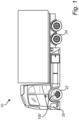
- Fig. 1 is an exemplary illustration of a vehicle 10 according to an example.
- the exemplified vehicle 10 is in the form of a truck.
- the vehicle 10 is depicted as comprising an engine 20, such as in the form of an electric traction motor for propelling the vehicle 10.
- the engine 20 may be connected to the foremost pair of rear wheels 24.
- Other alternatives are of course conceivable, such as connecting the engine to the front wheels 22 and/or to both the front pair of rear wheels 24 as well as to the front wheels 22, etc.
- Fig. 1 illustrates an electrically propelled vehicle 10
- the vehicle 10 may also be propelled by an engine 20 in the form of an internal combustion engine (not shown), either alone or in combination with the electric traction motor.
- the latter example is also conventionally referred to as a hybrid vehicle.
- the vehicle 10 comprises a braking arrangement 100, illustrated in the form of a service brake.
- the braking arrangement 100 is only depicted as arranged on the front wheels 22 but it should be readily understood that the braking arrangement 100 may be arranged on further wheels than the front wheels 22, such as for each of the wheels of the vehicle 10.
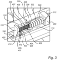
- Fig. 2 is an exemplary illustration of a wheel brake arrangement according to an example.
- the wheel brake arrangement 100 exemplified in Fig. 2 comprises a first brake pad module 102 and a second brake pad module 202, wherein the first brake pad module 102 comprises a first brake pad 104, while the second brake pad module 202 comprises a second brake pad 204.
- the first 102 and second 202 brake pad modules are axially 50 movable relative to each other.
- the first brake pad module 102 comprises a first backing plate 106 arranged as a support for the first brake pad 104.
- the second brake pad module 202 comprises a second backing plate 206 arranged as a support for the second brake pad 204.
- a rotatable brake disc is arranged between the first 102 and second 202 brake pad modules.
- the brake disc is connected to a wheel (e.g. 22 in Fig. 1 ) of the vehicle 10 whereby the wheel brake arrangement 100 is arranged to controllably reduce or control the rotational speed of the wheel 22 during operation of the vehicle 10.
- the exemplified wheel brake arrangement 100 further comprises a caliper 108 at least partially housing the brake pad modules 102, 202, as well as the brake disc 106.
- the caliper 108 comprises a first caliper part 108' and a second caliper part 108" which are connected to each other.
- the first 108' and second 108" caliper parts form an opening 111 of the caliper 108. By means of the opening 111, components of the brake pad arrangement 100 are accessible whereby maintenance thereof is simplified.
- the caliper 108 is a stationary portion 402 of the wheel brake arrangement 100.
- the wheel brake arrangement 100 comprises a further stationary portion 402 in the form of a retainer bar 110.
- the retainer bar 110 is preferably connected between the first 108' and second 108" caliper parts.
- the retainer bar 110 is connected to the second caliper part 108" by means of a screw connection and extends axially across each of the first 102 and second 202 brake pad modules, as well as the brake disc, thus forming a bridge radially above the opening 111.
- the wheel brake arrangement 100 further comprises a spring arrangement 300.
- the spring arrangement 300 is configured to force at least the first brake pad 104 axially away from the second brake pad 204 upon releasing the brake subsequent to a braking event/braking operation.
- the spring arrangement 300 is configured to force both the first 104 and second 204 brake pads away from the brake disc subsequent to the braking event.
- the wheel brake arrangement 100 further comprises a locking arrangement 400 configured to fixate the first brake pad module 102 at a predetermined distance away from the second brake pad module 202 subsequent to the braking event.
- the spring arrangement 300 comprises at least one coil spring 302, a first rod 304 comprising a first end portion 306 attached to a first end 308 of the at least one coil spring.
- the first rod 304 also comprises a second end portion 310 operatively connected to the first brake pad module (102 in Fig. 2 ).
- a second end 312 of the at least one coil spring 302 is operatively connected to the second brake pad module (202 in Fig. 2 ).
- the second end 312 of the at least one coil spring 302 is operatively connected to the second brake pad module via other components, such as via at least a mounting bracket 280 described in further detail below.
- the locking arrangement 400 is attached to the stationary portion 402 of the wheel brake arrangement, such as preferably the above described retainer bar 110.
- the locking arrangement 400 comprising a first locking member 404 which is slidable along a surface 406 of the first rod upon moving the first 104 and second 204 brake pads toward each other.
- the locking arrangement 400 also comprises a stop element 408.
- the stop element 408 is configured to lock the first locking element 404 to the surface 406 of the first rod 304 upon moving the first brake pad 104 a predetermined distance away from the second brake pad 204.
- the surface 406 of the first rod 304 is preferably a serrated surface 407.
- the serrated surface 407 comprises a plurality of saw teeth 409.
- the first locking element 406 is slidable along the serrated surface 407, and engaged with a sawtooth, i.e. one of the plurality of saw teeth 409 of the serrated surface 407 when the first brake pad 104 has moved the predetermined distance away from the second brake pad 204 upon releasing the brake, i.e. after the braking event.
- the first locking element 404 is locked to the serrated surface 407.
- the first locking element 404 hooks into one of the plurality of saw teeth 409 to maintain the first brake pad at the predetermined distance.
- the surface of the first brake pad 104 facing the second brake pad 204 will be arranged at the same predetermined distance form the second brake pad 204 as for a new and unused first brake pad. Accordingly, the surfaces of the first 104 and second 204 brake pads facing each other will remain at substantially the same distance from each other after a braking event irrespective of wear, and as a consequence, will be arranged at the same distance from the brake disc after the braking event.
- the first rod and the at least one coil spring are arranged coaxially with each other.
- the locking element 404 is preferably, and as indicated in Fig. 3 , a rotatable locking cam 405.
- the locking cam 405 is rotatably attached to the stationary portion 402 of the wheel brake arrangement 100.
- the rotatable locking cam 405 is in the exemplified illustration rotatably connected to a pin 410, which pin 410 in turn is fixated to the retainer bar 110.
- the rotatable locking cam 405 preferably comprises a nose portion arranged to slide along the serrated surface 407 of the first rod 304.
- the spring arrangement 300 comprises a second rod 304' in addition to the first rod 304.
- the second rod 304' comprises a first end portion 308' attached to the at least one coil spring 302.
- the first end portion 308' of the second rod 304' is attached to the second end of the at least one coil spring 302.
- the second rod 304 also comprises a second end 310' operatively connected to the second brake pad module 202.
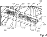
- Figs. 4-6 are detailed exemplary illustrations of a spring arrangement 300 and a locking arrangement 400 of the wheel brake arrangement 100 according to examples.
- the spring arrangement 300 comprises a second rod 304' in addition to the first rod 304.
- the second rod 304' comprises a first end portion 308' attached to the at least one coil spring 302.
- the first end portion 308' of the second rod 304' is attached to the second end of the at least one coil spring 302.
- the second rod 304 also comprises a second end 310' operatively connected to the second brake pad module 202.
- the second end 310' of the second rod 304 is preferably connected to a second radially extending plate member 320', which in turn is connected to the second brake pad module 202.
- the second radially extending plate member 320' is extending through a second opening 330' of the retainer bar 110 to be able to move along with the second brake pad module 202 upon braking and releasing the brake.
- the second radially extending plate member 320' is preferably attached to the second backing plate 106.
- the locking arrangement 400 also comprises a second locking member 404' which is slidable along a surface 406' of the second rod 304' upon moving the first and second brake pads toward each other.
- the locking arrangement 400 further comprises a second stop element 408' configured to lock the second locking element 404' to the surface 406' of the second rod 304' upon moving the first 104 and second 204 brake pads the predetermined distance away from each other.
- the surface 406' of the second rod 304' is, in a similar vein as the surface 406 of the first rod 304, a serrated surface 407', also referred to as the second serrated surface 407'.
- the second serrated surface 407' comprises a plurality of saw teeth 409'.
- the second locking element 404' is slidable along the second serrated surface 407', and engaged with a sawtooth, i.e. one of the plurality of saw teeth 409' of the second serrated surface 407' when the second brake pad 204 has moved the predetermined distance away from the first brake pad 104 upon releasing the brake, i.e. after the braking event.
- the locking arrangement 400 in Figs. 4-6 further comprises a second stop element 408' configured to lock the second locking element 404' to the surface of the second rod 304' upon moving the first 104 and second 204 brake pads the predetermined distance away from each other.
- the first coil spring 302 is arranged between the first rod 304 and the mounting bracket 280.
- the second rod 304' is arranged between the second brake pad module 202 and the second coil spring 302'.
- the second coil spring 302' is arranged between the second rod 304' and the mounting bracket 280.
- the at least one coil spring 302 is arranged in a spring housing 500.
- the spring housing 500 comprises a first spring housing 502 housing the first coil spring 302, and a second spring housing 502' housing the second coil spring 302'.
- the spring housing 500 is preferably attached to the mounting bracket 280.
- Example 1 A wheel brake arrangement for a wheel of a vehicle, the wheel brake arrangement comprising a first brake pad module comprising a first brake pad, and a second brake pad module comprising a second brake pad, the first and second brake pad modules being axially movable relative to each other, a spring arrangement comprising at least one coil spring, a first rod comprising a first end portion attached to a first end of the at least one coil spring and a second end portion operatively connected to the first brake pad module, wherein a second end of the at least one coil spring is operatively connected to the second brake pad module, and a locking arrangement attached to a stationary portion of the wheel brake arrangement, the locking arrangement comprising a first locking member slidable along a surface of the first rod upon moving the first and second brake pads toward each other, and a stop element configured to lock the first locking element to the surface of the first rod upon moving the first brake pad a predetermined distance away from the second brake pad.
- Example 2 The wheel brake arrangement of example 1, wherein the surface of the first rod is a serrated surface, the first locking element being engaged with a sawtooth of the serrated surface to lock the first locking element to the serrated surface when the first brake pad has moved the predetermined distance away from the second brake pad.
- Example 3 The wheel brake arrangement of example 2, wherein the first locking element is a locking cam rotatably attached to the stationary portion of the wheel brake arrangement.
- Example 4 The wheel brake arrangement of example 3, wherein the stop element is arranged in abutment with a first portion of the locking cam when the first brake pad has moved the predetermined distance away from the second brake pad to fixate a second portion of the locking cam to the sawtooth of the serrated surface.
- Example 5 The wheel brake arrangement of any one of the preceding examples, wherein the stop element is a stop pin.
- Example 6 The wheel brake arrangement of any one of the preceding examples, wherein the first rod and the at least one coil spring are arranged coaxially with each other.
- Example 7 The wheel brake arrangement of any one of the preceding examples, wherein the first brake pad module further comprises a radially extending plate member, wherein the second end portion of the first rod is attached to the radially extending plate member.
- Example 8 The wheel brake arrangement of example 7, wherein the first brake pad module further comprises a first backing plate supporting the first brake pad, wherein the radially extending plate member is attached to the first backing plate.
- Example 10 The wheel brake arrangement of example 9, wherein the locking arrangement further comprises a second locking member slidable along a surface of the second rod upon moving the first and second brake pads toward each other, and a second stop element configured to lock the second locking element to the surface of the second rod upon moving the first and second brake pads the predetermined distance away from each other.
- Example 11 The wheel brake arrangement of any one of examples 9 or 10, wherein the first rod, the second rod and the at least one coil spring are arranged coaxially with each other.
- Example 13 The wheel brake arrangement of example 12 when dependent on any one of examples 9 - 11, wherein the first coil spring is attached to the first rod and the second coil spring is attached to the second rod.
- Example 14 The wheel brake arrangement of example 13, wherein the spring arrangement further comprises a mounting bracket arranged between the first and second coil springs.
- Example 15 The wheel brake arrangement of any one of the preceding examples, further comprising a stationary retainer bar, wherein the stationary portion of the wheel brake arrangement is arranged on a surface of the stationary retainer bar.
- Example 16 The wheel brake arrangement of example 15, wherein the at least one coil spring is arranged in a spring housing attached to the stationary retainer bar.
- Example 17 The wheel brake arrangement of any one of the preceding examples, wherein the wheel brake arrangement further comprises a rotatable brake disc arranged axially between the first and second brake pads.
- Example 18 The wheel brake arrangement of example 17, wherein the first and second brake pad modules are movable towards and away from the rotatable brake disc.
- Example 19 A vehicle, comprising a wheel brake arrangement of any one of the preceding examples.
- Relative terms such as “below” or “above” or “upper” or “lower” or “horizontal” or “vertical” may be used herein to describe a relationship of one element to another element as illustrated in the Figures. It will be understood that these terms and those discussed above are intended to encompass different orientations of the device in addition to the orientation depicted in the Figures. It will be understood that when an element is referred to as being “connected” or “coupled” to another element, it can be directly connected or coupled to the other element, or intervening elements may be present. In contrast, when an element is referred to as being “directly connected” or “directly coupled” to another element, there are no intervening elements present.
Landscapes
- Engineering & Computer Science (AREA)
- General Engineering & Computer Science (AREA)
- Mechanical Engineering (AREA)
- Braking Arrangements (AREA)
Priority Applications (2)
| Application Number | Priority Date | Filing Date | Title |
|---|---|---|---|
| EP23205887.5A EP4545818A1 (de) | 2023-10-25 | 2023-10-25 | Radbremsanordnung |
| US18/914,448 US20250137507A1 (en) | 2023-10-25 | 2024-10-14 | Wheel brake arrangement |
Applications Claiming Priority (1)
| Application Number | Priority Date | Filing Date | Title |
|---|---|---|---|
| EP23205887.5A EP4545818A1 (de) | 2023-10-25 | 2023-10-25 | Radbremsanordnung |
Publications (1)
| Publication Number | Publication Date |
|---|---|
| EP4545818A1 true EP4545818A1 (de) | 2025-04-30 |
Family
ID=88510888
Family Applications (1)
| Application Number | Title | Priority Date | Filing Date |
|---|---|---|---|
| EP23205887.5A Pending EP4545818A1 (de) | 2023-10-25 | 2023-10-25 | Radbremsanordnung |
Country Status (2)
| Country | Link |
|---|---|
| US (1) | US20250137507A1 (de) |
| EP (1) | EP4545818A1 (de) |
Citations (4)
| Publication number | Priority date | Publication date | Assignee | Title |
|---|---|---|---|---|
| US20190056000A1 (en) * | 2016-04-13 | 2019-02-21 | Wabco Europe Bvba | Disc brake, in particular for utility vehicles |
| US20220299073A1 (en) * | 2021-03-22 | 2022-09-22 | Meritor Heavy Vehicle Braking Systems (Uk) Limited | Disc brake |
| US20220397166A1 (en) * | 2021-06-10 | 2022-12-15 | Mei Brakes Limited | Air Disc Brake for a Road Vehicle |
| US20230067490A1 (en) * | 2021-08-25 | 2023-03-02 | Zf Cv Systems Europe Bv | Disc brake for a motor vehicle |
-
2023
- 2023-10-25 EP EP23205887.5A patent/EP4545818A1/de active Pending
-
2024
- 2024-10-14 US US18/914,448 patent/US20250137507A1/en active Pending
Patent Citations (4)
| Publication number | Priority date | Publication date | Assignee | Title |
|---|---|---|---|---|
| US20190056000A1 (en) * | 2016-04-13 | 2019-02-21 | Wabco Europe Bvba | Disc brake, in particular for utility vehicles |
| US20220299073A1 (en) * | 2021-03-22 | 2022-09-22 | Meritor Heavy Vehicle Braking Systems (Uk) Limited | Disc brake |
| US20220397166A1 (en) * | 2021-06-10 | 2022-12-15 | Mei Brakes Limited | Air Disc Brake for a Road Vehicle |
| US20230067490A1 (en) * | 2021-08-25 | 2023-03-02 | Zf Cv Systems Europe Bv | Disc brake for a motor vehicle |
Also Published As
| Publication number | Publication date |
|---|---|
| US20250137507A1 (en) | 2025-05-01 |
Similar Documents
| Publication | Publication Date | Title |
|---|---|---|
| US7143873B2 (en) | Motor vehicle brake system comprising a parking brake function and electromechanical wheel brake for such a motor vehicle brake system | |
| CN102649426A (zh) | 用于调节在车辆中由驻车制动器施加的夹紧力的方法 | |
| AU2012307418A1 (en) | Disk brake of a motor vehicle and brake pad | |
| US12352327B2 (en) | Wheel brake arrangement | |
| US20160223082A1 (en) | Parking Lock for Motor Vehicles | |
| CN208216689U (zh) | 一种汽车刹车系统 | |
| EP4545818A1 (de) | Radbremsanordnung | |
| CN215762975U (zh) | 一种用于制动器摩擦片磨损用报警装置 | |
| EP4269831A1 (de) | Bremssattelanordnung, bremse und fahrzeug | |
| CN110410496B (zh) | 驻车机构及其使用方法和车辆 | |
| US7837014B2 (en) | High performance retrofit disk brake kit and method of use | |
| CN109099085A (zh) | 一种楔形增力式线控制动器 | |
| US20250146547A1 (en) | Disc Brake for a Utility Vehicle, and Brake Lining for a Disc Brake | |
| EP4571140A1 (de) | Radbremsanordnung | |
| CN210554765U (zh) | 四轮制动的电子驻车系统 | |
| CN109501781B (zh) | 一种消除液压盘式制动器启动阻滞的方法 | |
| CN116877599B (zh) | 一种车辆刹车装置 | |
| CN113734112A (zh) | 一种应用于新能源汽车的车档装置 | |
| CN221423747U (zh) | 一种防撞击结构及制动钳 | |
| GB1429629A (en) | Vehicle brake operating devices and to brake assemblies | |
| EP4219976A1 (de) | Feststellbremssattel mit umgekehrter hebelkonfiguration | |
| WO2002033282A1 (en) | Spring for retracting and retaining a pad in a caliper type disc brake assembly | |
| CN110043582A (zh) | 一种摩擦片降噪及主动回位结构 | |
| CN201264601Y (zh) | 汽车减速装置 | |
| US20010030089A1 (en) | Dragless brake caliper |
Legal Events
| Date | Code | Title | Description |
|---|---|---|---|
| PUAI | Public reference made under article 153(3) epc to a published international application that has entered the european phase |
Free format text: ORIGINAL CODE: 0009012 |
|
| STAA | Information on the status of an ep patent application or granted ep patent |
Free format text: STATUS: THE APPLICATION HAS BEEN PUBLISHED |
|
| AK | Designated contracting states |
Kind code of ref document: A1 Designated state(s): AL AT BE BG CH CY CZ DE DK EE ES FI FR GB GR HR HU IE IS IT LI LT LU LV MC ME MK MT NL NO PL PT RO RS SE SI SK SM TR |
|
| STAA | Information on the status of an ep patent application or granted ep patent |
Free format text: STATUS: REQUEST FOR EXAMINATION WAS MADE |
|
| 17P | Request for examination filed |
Effective date: 20251013 |