EP4545760A1 - INTERNAL COMBUSTION ENGINE - Google Patents
INTERNAL COMBUSTION ENGINE Download PDFInfo
- Publication number
- EP4545760A1 EP4545760A1 EP24199401.1A EP24199401A EP4545760A1 EP 4545760 A1 EP4545760 A1 EP 4545760A1 EP 24199401 A EP24199401 A EP 24199401A EP 4545760 A1 EP4545760 A1 EP 4545760A1
- Authority
- EP
- European Patent Office
- Prior art keywords
- exhaust gas
- down frame
- pipe
- gas sensor
- engine
- Prior art date
- Legal status (The legal status is an assumption and is not a legal conclusion. Google has not performed a legal analysis and makes no representation as to the accuracy of the status listed.)
- Granted
Links
Images



Classifications
-
- F—MECHANICAL ENGINEERING; LIGHTING; HEATING; WEAPONS; BLASTING
- F01—MACHINES OR ENGINES IN GENERAL; ENGINE PLANTS IN GENERAL; STEAM ENGINES
- F01N—GAS-FLOW SILENCERS OR EXHAUST APPARATUS FOR MACHINES OR ENGINES IN GENERAL; GAS-FLOW SILENCERS OR EXHAUST APPARATUS FOR INTERNAL-COMBUSTION ENGINES
- F01N3/00—Exhaust or silencing apparatus having means for purifying, rendering innocuous, or otherwise treating exhaust
- F01N3/08—Exhaust or silencing apparatus having means for purifying, rendering innocuous, or otherwise treating exhaust for rendering innocuous
- F01N3/10—Exhaust or silencing apparatus having means for purifying, rendering innocuous, or otherwise treating exhaust for rendering innocuous by thermal or catalytic conversion of noxious components of exhaust
-
- F—MECHANICAL ENGINEERING; LIGHTING; HEATING; WEAPONS; BLASTING
- F01—MACHINES OR ENGINES IN GENERAL; ENGINE PLANTS IN GENERAL; STEAM ENGINES
- F01N—GAS-FLOW SILENCERS OR EXHAUST APPARATUS FOR MACHINES OR ENGINES IN GENERAL; GAS-FLOW SILENCERS OR EXHAUST APPARATUS FOR INTERNAL-COMBUSTION ENGINES
- F01N13/00—Exhaust or silencing apparatus characterised by constructional features
- F01N13/008—Mounting or arrangement of exhaust sensors in or on exhaust apparatus
-
- F—MECHANICAL ENGINEERING; LIGHTING; HEATING; WEAPONS; BLASTING
- F01—MACHINES OR ENGINES IN GENERAL; ENGINE PLANTS IN GENERAL; STEAM ENGINES
- F01N—GAS-FLOW SILENCERS OR EXHAUST APPARATUS FOR MACHINES OR ENGINES IN GENERAL; GAS-FLOW SILENCERS OR EXHAUST APPARATUS FOR INTERNAL-COMBUSTION ENGINES
- F01N13/00—Exhaust or silencing apparatus characterised by constructional features
- F01N13/08—Other arrangements or adaptations of exhaust conduits
-
- F—MECHANICAL ENGINEERING; LIGHTING; HEATING; WEAPONS; BLASTING
- F01—MACHINES OR ENGINES IN GENERAL; ENGINE PLANTS IN GENERAL; STEAM ENGINES
- F01N—GAS-FLOW SILENCERS OR EXHAUST APPARATUS FOR MACHINES OR ENGINES IN GENERAL; GAS-FLOW SILENCERS OR EXHAUST APPARATUS FOR INTERNAL-COMBUSTION ENGINES
- F01N2340/00—Dimensional characteristics of the exhaust system, e.g. length, diameter or volume of the exhaust apparatus; Spatial arrangements of exhaust apparatuses
- F01N2340/04—Arrangement of the exhaust system relative to a vehicle or parts thereof
-
- F—MECHANICAL ENGINEERING; LIGHTING; HEATING; WEAPONS; BLASTING
- F01—MACHINES OR ENGINES IN GENERAL; ENGINE PLANTS IN GENERAL; STEAM ENGINES
- F01N—GAS-FLOW SILENCERS OR EXHAUST APPARATUS FOR MACHINES OR ENGINES IN GENERAL; GAS-FLOW SILENCERS OR EXHAUST APPARATUS FOR INTERNAL-COMBUSTION ENGINES
- F01N2560/00—Exhaust systems with means for detecting or measuring exhaust gas components or characteristics
- F01N2560/02—Exhaust systems with means for detecting or measuring exhaust gas components or characteristics the means being an exhaust gas sensor
- F01N2560/025—Exhaust systems with means for detecting or measuring exhaust gas components or characteristics the means being an exhaust gas sensor for measuring or detecting O2, e.g. lambda sensors
-
- F—MECHANICAL ENGINEERING; LIGHTING; HEATING; WEAPONS; BLASTING
- F01—MACHINES OR ENGINES IN GENERAL; ENGINE PLANTS IN GENERAL; STEAM ENGINES
- F01N—GAS-FLOW SILENCERS OR EXHAUST APPARATUS FOR MACHINES OR ENGINES IN GENERAL; GAS-FLOW SILENCERS OR EXHAUST APPARATUS FOR INTERNAL-COMBUSTION ENGINES
- F01N2560/00—Exhaust systems with means for detecting or measuring exhaust gas components or characteristics
- F01N2560/14—Exhaust systems with means for detecting or measuring exhaust gas components or characteristics having more than one sensor of one kind
-
- F—MECHANICAL ENGINEERING; LIGHTING; HEATING; WEAPONS; BLASTING
- F01—MACHINES OR ENGINES IN GENERAL; ENGINE PLANTS IN GENERAL; STEAM ENGINES
- F01N—GAS-FLOW SILENCERS OR EXHAUST APPARATUS FOR MACHINES OR ENGINES IN GENERAL; GAS-FLOW SILENCERS OR EXHAUST APPARATUS FOR INTERNAL-COMBUSTION ENGINES
- F01N2590/00—Exhaust or silencing apparatus adapted to particular use, e.g. for military applications, airplanes, submarines
- F01N2590/04—Exhaust or silencing apparatus adapted to particular use, e.g. for military applications, airplanes, submarines for motorcycles
Definitions
- the present disclosure relates to an engine.
- An engine for a straddle-type vehicle has an exhaust pipe that is curved in a U-shape in front of a down tube (see, for example, JP3489242B ).
- a cylinder is disposed on a crank case, and a cylinder head is disposed on the cylinder.
- An exhaust port is formed in a front surface of the cylinder head, and an exhaust pipe extends downward from the exhaust port toward the crank case.
- the exhaust pipe is curved upward in a U-shape and extends to the cylinder, and the exhaust pipe passes through a lateral side of the cylinder and extends to a rear side of the vehicle and then connected to a muffler.
- an exhaust gas sensor is attached to the exhaust pipe, but if the exhaust pipe has many bends, the flow of exhaust gas is deviated, thereby deteriorating detection accuracy of the exhaust gas sensor. Depending on where the exhaust gas sensor is disposed, there is a high risk of damage to the exhaust gas sensor or a lead wire.
- Non-limiting embodiments of the present disclosure relates to provide an engine capable of reducing the risk of damage to the exhaust gas sensor in a model in which the exhaust pipe passes through the lateral side of the cylinder.
- aspects of certain non-limiting embodiments of the present disclosure address the features discussed above and/or other features not described above. However, aspects of the non-limiting embodiments are not required to address the above features, and aspects of the non-limiting embodiments of the present disclosure may not address features described above.
- an engine for a straddle-type vehicle to be mounted on a vehicle frame in which a down frame extends downward from a head pipe the engine including:
- An engine is mounted on a vehicle frame of a straddle-type vehicle.
- An exhaust port is formed in a cylinder head of the engine, and an exhaust pipe is connected to the exhaust port of the cylinder head, and an exhaust gas sensor is attached to the exhaust pipe.
- a down frame extends downward from a head pipe of the vehicle frame, and the exhaust pipe extends downward through one lateral side of the down frame. After crossing a front side of the down frame, the exhaust pipe passes through the other lateral side of the down frame and extends upward.
- a part of the exhaust pipe that crosses the down frame is a straight portion, and the exhaust gas sensor is attached to the straight portion and overlaps the down frame from the front side.
- the exhaust gas sensor is attached to the straight portion where the flow of exhaust gas is less deviated, and the exhaust gas sensor overlaps the down frame from the front side and is approximately perpendicular to the straight portion.
- the detection accuracy is improved by directing the detection end of the exhaust gas sensor approximately perpendicular to the flow of the exhaust gas.
- the straight portion of the exhaust pipe vibrates less than a bent portion, allowing the exhaust gas sensor to be stably supported, and the exhaust gas sensor is positioned on the inside in the vehicle width direction, thereby reducing the risk of damage to the exhaust gas sensor when the vehicle rolls over.
- FIG. 1 is a right side view of the straddle-type vehicle according to the present embodiment.
- an arrow FR indicates a vehicle front side
- an arrow RE indicates a vehicle rear side
- an arrow L indicates a vehicle left side
- an arrow R indicates a vehicle right side.
- a straddle-type vehicle 1 is implemented by mounting various components such as an engine 40 and an electrical system on a vehicle frame 10.
- a pair of main frames 12 extend obliquely rearward and downward from a head pipe 11 (see FIG. 2 ) of the vehicle frame 10, and rear portions of the pair of main frames 12 form a pair of body frames 13 bent downward.
- a down frame 14 extends downward from the head pipe 11, and an under loop 15 bent rearward is connected to a lower portion of the down frame 14. Rear ends of the pair of under loops 15 are connected to lower portions of the pair of body frames 13, so that the vehicle frame 10 is formed into a cradle shape.
- a front fork 25 is steerably supported by the head pipe 11 via a steering shaft (not shown).
- a handle 26 is provided at an upper portion of the front fork 25, and a front wheel 27 is rotatably supported by a lower portion of the front fork 25.
- a fuel tank 31 is placed over upper portions of the pair of main frames 12, and the main frames 12 and the fuel tank 31 are covered by a front side cover 33 from a lateral side.
- a seat 32 is disposed behind the fuel tank 31, and a seat frame 16 (see FIG. 2 ) that supports the seat 32 from below is covered by a rear side cover 34 from a lateral side.
- a swing arm 35 is swingably supported on the body frame 13.
- the swing arm 35 extends rearward from the body frame 13, and a rear wheel 36 is rotatably supported at a rear end of the swing arm 35.
- the engine 40 is a four-stroke single-cylinder engine, and is suspended inside the vehicle frame 10 via a plurality of suspension brackets.
- a cylinder assembly in which a cylinder 42, a cylinder head 43, and a cylinder head cover 44 are stacked is attached to an upper portion of a crank case 41 of the engine 40.
- an air cleaner 48 is disposed at a rear side of the cylinder head 43.
- Left and right radiators 51, 55 are positioned in front of the cylinder head 43.
- the left and right radiators 51, 55 are attached to the down frame 14.
- An exhaust pipe 70 extends downward from a left side of a front surface of the cylinder head 43.
- the exhaust pipe 70 passes through a right lateral side of the cylinder 42 and is connected to a muffler 79 at a rear side of the vehicle.
- a primary catalyst case 74 is formed in the exhaust pipe 70 in front of the crank case 41.
- a secondary catalyst case 78 is formed in the exhaust pipe 70 behind the air cleaner 48.
- the primary catalyst case 74 accommodates a primary catalyst 81.
- the secondary catalyst case 78 accommodates a secondary catalyst 82.
- the exhaust pipe 70 has many bends, which causes the flow of the exhaust gas inside the exhaust pipe 70 to deviate, resulting in poor detection accuracy depending on a position where the oxygen sensor is disposed. There is a high risk of damage to the oxygen sensor and a lead wire in front of the crank case 41.
- the cooling water flows upward from the right inlet tank 52 toward the right outlet tank 54, and while the cooling water passes through the right radiator core 53, the heat of the cooling water is radiated into the air.
- the cooling water is sent from the right outlet tank 54 to the left inlet tank 56, through the inter-radiator hose 63.
- the cooling water flows downward from the left inlet tank 56 toward the left outlet tank 58, and while the cooling water passes through the left radiator core 57, the heat of the cooling water is radiated into the air.
- the heat of the cooling water is radiated in two stages by the right radiator 51 and the left radiator 55, so that cooling efficiency is improved.
- a guard member 83 protrudes upward from the straight portion 73 of the diameter-enlarged pipe 72.
- a first oxygen sensor (exhaust gas sensor) 84 is attached to an upper surface of the straight portion 73 behind the guard member 83, in a front view.
- the first oxygen sensor 84 is positioned in front of the down frame 14.
- the first oxygen sensor 84 is sandwiched between the down frame 14 and the guard member 83 from the front and rear sides.
- the first oxygen sensor 84 is protected by the guard member 83 and the down frame 14.
- the downstream side of the diameter-reduced pipe 75 is positioned on the lateral side of the cylinder 42.
- a second oxygen sensor 86 is attached to the diameter-reduced pipe 75 on the lateral side of the cylinder 42.
- a base end of the second oxygen sensor 86 faces inward in the vehicle width direction.
- a base end of the second oxygen sensor 86 is positioned in a space surrounded by the peripheral components such as the right radiator 51, the cylinder head 43, the inlet hose 62, and the diameter-reduced pipe 75.
- the second oxygen sensor 86 is protected by the peripheral components.
- the second oxygen sensor 86 is positioned at a downstream side of the diameter-reduced pipe 75 where the diameter is reduced, and even when the diameter-reduced pipe 75 is curved, the exhaust gas is not likely to hit a detection end of the second oxygen sensor 86, so that the detection accuracy will not be impaired.
- the downstream pipe 76 extends rearward from the downstream end of the diameter-reduced pipe 75 and passes through the right lateral side of the cylinder 42.
- the diameter-enlarged pipe 77 is enlarged in diameter from the downstream end of the downstream pipe 76 toward the rear side.
- the secondary catalyst case 78 is formed to have a larger diameter than the downstream pipe 76.
- the secondary catalyst 82 (see FIG. 1 ) is accommodated inside the secondary catalyst case 78. Air pollutants in the exhaust gas are purified as the exhaust gas passes through the secondary catalyst 82.
- the muffler 79 is connected to the downstream end of the secondary catalyst case 78. Exhaust gas that passes through the secondary catalyst 82 is discharged from the muffler 79 to the outside.
- the diameter-enlarged pipe 72 is formed in a hollow structure constituted by front and rear pipe halves.
- the primary catalyst case 74 and the diameter-reduced pipe 75 are also formed in a hollow structure constituted by left and right pipe halves. Therefore, mounting bosses for the first and second oxygen sensors 84, 86 can be easily provided on each of the pipe halves.
- the first oxygen sensor 84 is configured to detect an oxygen concentration in the exhaust gas.
- the second oxygen sensor 86 is configured to detect an oxygen concentration in the exhaust gas that passes through the primary catalyst 81.
- a detection result of the first oxygen sensor 84 is used for feedback control of a fuel injection amount, and a detection result of the second oxygen sensor 86 is used for diagnosing catalyst deterioration.
- a first lead wire 85 extends upward from a base end of the first oxygen sensor 84 (see FIG. 2 ), and a second lead wire 87 extends upward from the base end of the second oxygen sensor 86.
- the right radiator 51 is provided with a shroud 66 that covers the right radiator core 53, and the shroud 66 is provided with cable holders 67, 68.
- the first lead wire 85 is held by the suspension bracket 23 (see FIG. 3 ) of the down frame 14 and then extends toward the second oxygen sensor 86 and is held together with the first lead wire 85 by the cable holders 67, 68 of the shroud 66.
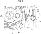
- FIG. 5 is a cross-sectional view of the engine in FIG. 3 taken along a line V-V
- FIG. 6 is a cross-sectional view of the engine in FIG. 3 taken along a line VI-VI.
- the straight portion 73 of the exhaust pipe 70 extends across the front side of the down frame 14 in the vehicle width direction.
- the guard member 83 protrudes from an upper surface of the straight portion 73.
- the first oxygen sensor 84 is attached to a back side of the guard member 83 from the upper surface of the straight portion 73.
- the straight portion 73 of the exhaust pipe 70 vibrates less than a bent portion, so that the first oxygen sensor 84 is supported stably.
- the first oxygen sensor 84 overlaps the down frame 14 from the front side, and the first oxygen sensor 84 is approximately perpendicular to the straight portion 73, so that the detection accuracy is stable.
- an extension line L1 of an upper edge of the upstream pipe 71 is extended to the right lateral side, so that the diameter-enlarged pipe 72 is divided into upper and lower parts.
- the first oxygen sensor 84 is attached to a lower area of the diameter-enlarged pipe 72.
- the first oxygen sensor 84 is not attached to an upper area of the diameter-enlarged pipe 72.
- the lower area of the diameter-enlarged pipe 72 is the straight portion 73 where the flow rate of the exhaust gas is high, thereby improving exhaust gas exchange performance and reducing deviation of the flow of the exhaust gas.
- the detection accuracy is improved by directing the detection end of the first oxygen sensor 84 approximately perpendicular to the flow of the exhaust gas.
- the first oxygen sensor 84 extends in a manner of being parallel to the down frame 14, and the first oxygen sensor 84 is positioned inside both side surfaces of the down frame 14 in an engine width direction.
- the first lead wire 85 extending from the base end (upper end) of the first oxygen sensor 84 can be easily routed along the down frame 14.
- the down frame 14 and the guard member 83 face each other in the front-rear direction.
- the first oxygen sensor 84 is sandwiched between the down frame 14 and the guard member 83. At the front side of the engine 40, the first oxygen sensor 84 is protected by the down frame 14 and the guard member 83 from the front and rear sides.
- the first oxygen sensor 84 overlaps the exhaust pipe 70 passing through both lateral sides of the down frame 14 (see FIG. 2 ).
- the upstream pipe 71 is positioned on the left lateral side of the first oxygen sensor 84.
- the primary catalyst case 74 is positioned on the right lateral side of the first oxygen sensor 84.
- the first oxygen sensor 84 is protected by the upstream pipe 71 and the primary catalyst case 74, thereby reducing the risk of damage to the first oxygen sensor 84 when the vehicle rolls over.
- the primary catalyst 81 is accommodated inside the primary catalyst case 74, and is positioned so that the primary catalyst 81 overlaps the first oxygen sensor 84 in a side view (see FIG. 2 ).
- the primary catalyst 81 is positioned above a lower end of the down frame 14 and the under loop 15 and below the exhaust port 47.
- an upper end of the primary catalyst 81 is inclined so as to be positioned outside a lower end of the primary catalyst 81 in the vehicle width direction.
- the lower end of the primary catalyst 81 is inclined so as to be positioned in front of the upper end of the primary catalyst 81 (see FIG. 2 ).
- the primary catalyst 81 overlaps the down frame 14, and the lower end of the primary catalyst 81 is positioned in front of the down frame 14 (see FIG. 2 ).
- an axis C1 of the first oxygen sensor 84 is inclined so as to approach an axis C2 of the down frame 14, in a side view. Since the first oxygen sensor 84 is slightly inclined rearward, the risk of damage due to a collision with a flying stone or the like from the front side is reduced.
- the first lead wire 85 (see FIG. 6 ) can be easily routed along the down frame 14.
- the axis C1 of the first oxygen sensor 84 extends approximately parallel to an axis of the front fork 25 (see FIG. 1 ), and the first oxygen sensor 84 is positioned inside both end positions P1, P2 of the straight portion 73 in the front-rear direction. Since the first oxygen sensor 84 does not protrude from the straight portion 73, a gap is ensured between the first oxygen sensor 84 and the down frame 14 or the front wheel 27, and there is no need to extend a wheelbase to attach the first oxygen sensor 84.
- the guard member 83 protrudes vertically from the straight portion 73, and an upper end of the guard member 83 is positioned above the base end of the first oxygen sensor 84.
- the first oxygen sensor 84 is inclined upward and away from the guard member 83. The further upward the first oxygen sensor 84 is, the farther it is away from the guard member 83, so that even in a case where the guard member 83 is hit by a flying stone or the like and deformed, influence on the first oxygen sensor 84 is reduced.
- Providing the gap between the first oxygen sensor 84 and the guard member 83 makes it easier to attach the first oxygen sensor 84 and to route the first lead wire 85.
- the under loop 15 is curved downward and rearward from the down frame 14.
- the first oxygen sensor 84 is positioned above the extension line L2. Since the first oxygen sensor 84 is positioned above the extension line L2 of the under loop 15, the exhaust pipe 70 (straight portion 73) is positioned higher. Therefore, when the straddle-type vehicle 1 passes over an obstacle, the first oxygen sensor 84 does not hit the obstacle, and even when the exhaust pipe 70 interferes with the obstacle and is dented, the risk of damage to the first oxygen sensor 84 is reduced.
- the guard member 83 is formed in an arc shape when viewed from above, and the first oxygen sensor 84 is positioned between the guard member 83 and the down frame 14.
- the guard member 83 and the down frame 14 are brought close to the first oxygen sensor 84 from the front and rear sides, and the first oxygen sensor 84 is covered by the down frame 14 from the rear side, so that it is not necessary to form the guard member 83 around the entire periphery.
- the guard member 83 is no longer necessary behind the first oxygen sensor 84, and a working space is ensured between the down frame 14 and the guard member 83 when the first oxygen sensor 84 is attached with a tool, thereby preventing deterioration of the ease of assembly.
- the first oxygen sensor 84 is attached to the straight portion 73 where the flow of the exhaust gas is less deviated, and the first oxygen sensor 84 overlaps the down frame 14 from the front side and is approximately perpendicular to the straight portion 73.
- the detection accuracy is improved by directing the detection end of the first oxygen sensor 84 approximately perpendicular to the flow of the exhaust gas.
- the straight portion 73 of the exhaust pipe 70 vibrates less than a bent portion, allowing the first oxygen sensor 84 to be stably supported, and the first oxygen sensor 84 is positioned on the inside in the vehicle width direction, thereby reducing the risk of damage to the first oxygen sensor 84 when the vehicle rolls over.
- the exhaust pipe extends downward from the cylinder head, and the exhaust pipe is largely curved in front of the crank case, and then extends rearward passing through the lateral side of the cylinder, but the exhaust pipe may extend rearward from the cylinder head passing through the lateral side of the cylinder.
- the exhaust pipe may extend from the cylinder head toward a lateral side and then extend rearward passing through the lateral side of the cylinder.
- an oxygen sensor is used as an example of an exhaust gas sensor, but the exhaust gas sensor may be any sensor capable of detecting average characteristics of the exhaust gas, and may be, for example, an exhaust temperature sensor that detects an exhaust temperature of the exhaust gas.
- the first oxygen sensor serving as an exhaust gas sensor is attached to the straight portion of the diameter-enlarged pipe, but the exhaust gas sensor may be attached to the straight portion of the exhaust pipe that crosses the down frame.
- the exhaust pipe is provided with the primary catalyst case and the secondary catalyst case, but it is sufficient that the exhaust device is provided with at least one catalyst case.
- the vehicle frame is provided with an under loop, but the shape of the vehicle frame is not particularly limited as long as an under frame extends downward from at least the head pipe in the vehicle frame.
- a water-cooled engine is exemplified as the engine, but the engine may be an air-cooled engine or an oil-cooled engine.
- the exhaust pipe in the present embodiment may be a single pipe or a double pipe.
- the engine of the present embodiment is not limited to being used in the off-road type straddle-type vehicle described above, and may be used in other types of straddle-type vehicles.
- the straddle-type vehicle is not limited to a general vehicle in which a driver rides on a seat in a posture straddling the seat, and includes a scooter-type vehicle in which the driver rides on the seat without straddling the seat.
- a first aspect is an engine (40) for a straddle-type vehicle (1) to be mounted on a vehicle frame (10) in which a down frame (14) extends downward from a head pipe (11), the engine including: a cylinder head (43) having an exhaust port (47) formed therein; an exhaust pipe (70) connected to the exhaust port of the cylinder head; and an exhaust gas sensor (first oxygen sensor 84) attached to the exhaust pipe, in which the exhaust pipe extends downward passing through one lateral side of the down frame, crosses a front side of the down frame, and then extends upward passing through the other lateral side of the down frame, a part of the exhaust pipe that crosses the down frame is a straight portion (73), and the exhaust gas sensor is attached to the straight portion and overlaps the down frame from the front side.
- the exhaust gas sensor is attached to the straight portion where the flow of exhaust gas is less deviated, and the exhaust gas sensor overlaps the down frame from the front side and is approximately perpendicular to the straight portion.
- the detection accuracy is improved by directing the detection end of the exhaust gas sensor approximately perpendicular to the flow of the exhaust gas.
- the straight portion of the exhaust pipe vibrates less than a bent portion, allowing the exhaust gas sensor to be stably supported, and the exhaust gas sensor is positioned on the inside in the vehicle width direction, thereby reducing the risk of damage to the exhaust gas sensor when the vehicle rolls over.
- the exhaust gas sensor in a front view, extends in an upper-lower direction in a manner of being parallel to the down frame, and the exhaust gas sensor is positioned inside both side surfaces of the down frame in an engine width direction. According to this configuration, the exhaust gas sensor is attached approximately perpendicular to the straight portion of the exhaust pipe, thereby making it possible to further improve the detection accuracy.
- the lead wire of the exhaust gas sensor can be easily routed along the down frame.
- an axis of the exhaust gas sensor is inclined upward in a manner of approaching an axis of the down frame. According to this configuration, the risk of damage to the exhaust gas sensor due to a collision with a flying stone or the like from the front side is reduced by being inclined rearward.
- the lead wire of the exhaust gas sensor can be easily routed along the down frame, and by routing the lead wire along the down frame, vibration of the lead wire can be prevented.
- the exhaust gas sensor is positioned inside both ends of the straight portion in a front-rear direction in a side view. According to this configuration, the exhaust gas sensor does not protrude forward or rearward from the straight portion, so that a gap is ensured between the exhaust gas sensor and the down frame or the front wheel, and there is no need to extend the wheelbase to attach the exhaust gas sensor.
- the exhaust gas sensor overlaps the exhaust pipe passing through both lateral sides of the down frame in a side view. According to this configuration, the exhaust gas sensor is protected from both lateral sides by the exhaust pipe, and the risk of damage to the exhaust gas sensor due to the vehicle rolling over or the like can be reduced.
- a catalyst (primary catalyst 81) is accommodated in the exhaust pipe on the other lateral side of the down frame, and the catalyst overlaps the exhaust gas sensor in a side view. According to this configuration, by bringing the catalyst closer to the exhaust gas sensor, the heat of the catalyst can be utilized to activate the exhaust gas sensor early, thereby improving the detection accuracy.
- a guard member (83) protrudes from the straight portion, and the exhaust gas sensor is covered by the guard member from the front side. According to this configuration, the exhaust gas sensor is covered by the guard member from the front side, and the exhaust gas sensor is protected by the guard member, thereby reducing the risk of damage.
- the guard member protrudes vertically from the straight portion in a side view, and the exhaust gas sensor is inclined upward in a manner of being away from the guard member. According to this configuration, the further upward the exhaust gas sensor is, the farther it is away from the guard member, so that even when the guard member is hit by a flying stone or the like and deformed, influence on the exhaust gas sensor is reduced. Providing a gap between the exhaust gas sensor and the guard member makes it easier to attach the exhaust gas sensor and to route the lead wire.
Landscapes
- Engineering & Computer Science (AREA)
- Chemical & Material Sciences (AREA)
- Combustion & Propulsion (AREA)
- Mechanical Engineering (AREA)
- General Engineering & Computer Science (AREA)
- Analytical Chemistry (AREA)
- Health & Medical Sciences (AREA)
- Chemical Kinetics & Catalysis (AREA)
- Toxicology (AREA)
- Exhaust Silencers (AREA)
- Exhaust Gas After Treatment (AREA)
Abstract
Description
- The present disclosure relates to an engine.
- An engine for a straddle-type vehicle has an exhaust pipe that is curved in a U-shape in front of a down tube (see, for example,
JP3489242B JP3489242B - Incidentally, an exhaust gas sensor is attached to the exhaust pipe, but if the exhaust pipe has many bends, the flow of exhaust gas is deviated, thereby deteriorating detection accuracy of the exhaust gas sensor. Depending on where the exhaust gas sensor is disposed, there is a high risk of damage to the exhaust gas sensor or a lead wire.
- Aspect of non-limiting embodiments of the present disclosure relates to provide an engine capable of reducing the risk of damage to the exhaust gas sensor in a model in which the exhaust pipe passes through the lateral side of the cylinder.
- Aspects of certain non-limiting embodiments of the present disclosure address the features discussed above and/or other features not described above. However, aspects of the non-limiting embodiments are not required to address the above features, and aspects of the non-limiting embodiments of the present disclosure may not address features described above.
- According to an aspect of the present disclosure, there is provided an engine for a straddle-type vehicle to be mounted on a vehicle frame in which a down frame extends downward from a head pipe, the engine including:
- a cylinder head having an exhaust port formed thereon;
- an exhaust pipe connected to the exhaust port of the cylinder head; and
- an exhaust gas sensor attached to the exhaust pipe,
- in which the exhaust pipe extends downward passing through a first lateral side of the down frame, crosses a front side of the down frame, and extends upward passing through a second lateral side of the down frame,
- a part of the exhaust pipe that crosses the down frame is a straight portion, and
- the exhaust gas sensor is attached to the straight portion and overlaps the down frame from the front side.
- Exemplary embodiment(s) of the present invention will be described in detail based on the following figures, wherein:
-
FIG. 1 is a right side view of a straddle-type vehicle according to an embodiment; -
FIG. 2 is a right side view of a periphery of an engine according to the present embodiment; -
FIG. 3 is a front view of the periphery of the engine according to the present embodiment; -
FIG. 4 is a perspective view of the periphery of the engine according to the present embodiment when obliquely viewed from a rear and right side; -
FIG. 5 is a cross-sectional view of the engine inFIG. 3 taken along a line V-V; and -
FIG. 6 is a cross-sectional view of the engine inFIG. 3 taken along a line VI-VI. - An engine according to one aspect of the present disclosure is mounted on a vehicle frame of a straddle-type vehicle. An exhaust port is formed in a cylinder head of the engine, and an exhaust pipe is connected to the exhaust port of the cylinder head, and an exhaust gas sensor is attached to the exhaust pipe. A down frame extends downward from a head pipe of the vehicle frame, and the exhaust pipe extends downward through one lateral side of the down frame. After crossing a front side of the down frame, the exhaust pipe passes through the other lateral side of the down frame and extends upward. A part of the exhaust pipe that crosses the down frame is a straight portion, and the exhaust gas sensor is attached to the straight portion and overlaps the down frame from the front side. The exhaust gas sensor is attached to the straight portion where the flow of exhaust gas is less deviated, and the exhaust gas sensor overlaps the down frame from the front side and is approximately perpendicular to the straight portion. The detection accuracy is improved by directing the detection end of the exhaust gas sensor approximately perpendicular to the flow of the exhaust gas. The straight portion of the exhaust pipe vibrates less than a bent portion, allowing the exhaust gas sensor to be stably supported, and the exhaust gas sensor is positioned on the inside in the vehicle width direction, thereby reducing the risk of damage to the exhaust gas sensor when the vehicle rolls over. By routing the lead wire of the exhaust gas sensor along the down frame, it is possible to prevent vibration of the lead wire and reduce the risk of damage to the lead wire.
- Hereinafter, a straddle-type vehicle according to the present embodiment will be described with reference to the accompanying drawings.
FIG. 1 is a right side view of the straddle-type vehicle according to the present embodiment. In the following drawings, an arrow FR indicates a vehicle front side, an arrow RE indicates a vehicle rear side, an arrow L indicates a vehicle left side, and an arrow R indicates a vehicle right side. - As shown in
FIG. 1 , a straddle-type vehicle 1 is implemented by mounting various components such as anengine 40 and an electrical system on avehicle frame 10. A pair ofmain frames 12 extend obliquely rearward and downward from a head pipe 11 (seeFIG. 2 ) of thevehicle frame 10, and rear portions of the pair ofmain frames 12 form a pair ofbody frames 13 bent downward. Adown frame 14 extends downward from thehead pipe 11, and an underloop 15 bent rearward is connected to a lower portion of thedown frame 14. Rear ends of the pair of underloops 15 are connected to lower portions of the pair ofbody frames 13, so that thevehicle frame 10 is formed into a cradle shape. - A
front fork 25 is steerably supported by thehead pipe 11 via a steering shaft (not shown). Ahandle 26 is provided at an upper portion of thefront fork 25, and afront wheel 27 is rotatably supported by a lower portion of thefront fork 25. Afuel tank 31 is placed over upper portions of the pair ofmain frames 12, and themain frames 12 and thefuel tank 31 are covered by afront side cover 33 from a lateral side. Aseat 32 is disposed behind thefuel tank 31, and a seat frame 16 (seeFIG. 2 ) that supports theseat 32 from below is covered by arear side cover 34 from a lateral side. - A
swing arm 35 is swingably supported on thebody frame 13. Theswing arm 35 extends rearward from thebody frame 13, and arear wheel 36 is rotatably supported at a rear end of theswing arm 35. Theengine 40 is a four-stroke single-cylinder engine, and is suspended inside thevehicle frame 10 via a plurality of suspension brackets. A cylinder assembly in which acylinder 42, acylinder head 43, and acylinder head cover 44 are stacked is attached to an upper portion of acrank case 41 of theengine 40. At a rear side of thecylinder head 43, anair cleaner 48 is disposed. - Left and
right radiators 51, 55 (only theright radiator 51 is shown inFIG. 1 ) are positioned in front of thecylinder head 43. The left andright radiators down frame 14. Anexhaust pipe 70 extends downward from a left side of a front surface of thecylinder head 43. Theexhaust pipe 70 passes through a right lateral side of thecylinder 42 and is connected to amuffler 79 at a rear side of the vehicle. Aprimary catalyst case 74 is formed in theexhaust pipe 70 in front of thecrank case 41. Asecondary catalyst case 78 is formed in theexhaust pipe 70 behind theair cleaner 48. Theprimary catalyst case 74 accommodates aprimary catalyst 81. Thesecondary catalyst case 78 accommodates asecondary catalyst 82. - When the
primary catalyst case 74 is provided in front of thecrank case 41, it is difficult to provide an oxygen sensor on an upstream side or a downstream side of theprimary catalyst case 74. In the straddle-type vehicle 1 of the present embodiment, theexhaust pipe 70 has many bends, which causes the flow of the exhaust gas inside theexhaust pipe 70 to deviate, resulting in poor detection accuracy depending on a position where the oxygen sensor is disposed. There is a high risk of damage to the oxygen sensor and a lead wire in front of thecrank case 41. Therefore, in the present embodiment, the oxygen sensor is provided at the straight portion in theexhaust pipe 70, where the flow of the exhaust gas is less deviated and the risk of damage is low, and at a position overlapping the down frame, which serves as a route for routing the lead wire, from the front side. - Peripheral structures of the engine will now be described with reference to
FIGS. 2 to 4 .FIG. 2 is a right side view of a periphery of the engine according to the present embodiment.FIG. 3 is a front view of the periphery of the engine according to the present embodiment.FIG. 4 is a perspective view of the periphery of the engine according to the present embodiment when obliquely viewed from a rear and right side. - As shown in
FIG. 2 , the pair ofmain frames 12 and thedown frame 14 are connected to each other viabridge tubes 17 for reinforcement at an upper portion of thevehicle frame 10. Below thebridge tubes 17, theengine 40 is suspended from thevehicle frame 10 bysuspension brackets 21 to 23. Aclutch cover 45 is attached to a right side surface of thecrank case 41 of theengine 40. Awater pump 46 is provided in front of theclutch cover 45. A discharge port of thewater pump 46 is connected to a cooling passage in thecrank case 41. A cooling water is delivered from thewater pump 46 to the inside of thecylinder 42 and to a water jacket in thecylinder head 43. - As shown in
FIGS. 2 and3 , theright radiator 51 and theleft radiator 55 are provided in front of thecylinder head 43 with thedown frame 14 at a center of the vehicle interposed between theright radiator 51 and theleft radiator 55. Theright radiator 51 is formed to be larger than theleft radiator 55. In theright radiator 51, aright inlet tank 52 is provided below aright radiator core 53, and aright outlet tank 54 is provided above theright radiator core 53. In theleft radiator 55, aleft inlet tank 56 is provided above aleft radiator core 57, and aleft outlet tank 58 is provided below theleft radiator core 57. - A
thermostat cover 61 is provided on a front surface of theengine 40. A thermostat (not shown) is provided inside thethermostat cover 61. Theright inlet tank 52 is connected to thethermostat cover 61 via aninlet hose 62. Theright outlet tank 54 and theleft inlet tank 56 are connected to each other via aninter-radiator hose 63. Theleft outlet tank 58 is connected to thewater pump 46 via anoutlet hose 64. An upper portion of thethermostat cover 61 is connected to theright outlet tank 54 via anair vent hose 65. - In the
right radiator 51, the cooling water flows upward from theright inlet tank 52 toward theright outlet tank 54, and while the cooling water passes through theright radiator core 53, the heat of the cooling water is radiated into the air. The cooling water is sent from theright outlet tank 54 to theleft inlet tank 56, through theinter-radiator hose 63. In theleft radiator 55, the cooling water flows downward from theleft inlet tank 56 toward theleft outlet tank 58, and while the cooling water passes through theleft radiator core 57, the heat of the cooling water is radiated into the air. The heat of the cooling water is radiated in two stages by theright radiator 51 and theleft radiator 55, so that cooling efficiency is improved. - The
cylinder head 43 and an intermediate portion of theoutlet hose 64 are connected via a bypass hose (not shown). A bypass passage is formed by the bypass hose that bypasses theright radiator 51 and theleft radiator 55. A bypass passage is configured to return the cooling water from the cylinder head 43 (upstream of the thermostat) to thewater pump 46. In a case where a temperature of the cooling water is lower than a predetermined temperature, the thermostat closes and the cooling water is returned from thecylinder head 43 through the bypass hose to thewater pump 46. In a case where the temperature of the cooling water is equal to or higher than the predetermined temperature, the thermostat opens, and the cooling water flows into theright radiator 51 and theleft radiator 55 to cool theengine 40. - An
exhaust port 47 obliquely facing a left and lower side is formed in the front surface of thecylinder head 43, and theexhaust pipe 70 is connected to theexhaust port 47. Theexhaust pipe 70 extends downward from theexhaust port 47 passing through the left lateral side of thedown frame 14, crosses a front side of thedown frame 14, and then extends upward passing through the right lateral side of thedown frame 14. Theexhaust pipe 70 is curved into a U-shape using a space in front of the vehicle body, so that a radius of curvature of a curved portion of theexhaust pipe 70 becomes large, and exhaust resistance is reduced. Theexhaust pipe 70 extends rearward passing through the right lateral side of thecylinder 42. A rear end of theexhaust pipe 70 is connected to themuffler 79 near theseat 32. - The
exhaust pipe 70 is formed by connecting anupstream pipe 71, a diameter-enlargedpipe 72, theprimary catalyst case 74, a diameter-reducedpipe 75, adownstream pipe 76, a diameter-enlarged pipe 77 (seeFIG. 1 ), and the secondary catalyst case 78 (seeFIG. 1 ). Theupstream pipe 71 obliquely extends to a left and lower side from theexhaust port 47 and then is curved to toward the right side. The diameter-enlargedpipe 72 extends rightward from a downstream end of theupstream pipe 71, crosses the front side of thedown frame 14, and then is obliquely curved to an upper and right side. A front half of the diameter-enlargedpipe 72 that crosses thedown frame 14 is astraight portion 73 having a straight pipe shape. A rear half of the diameter-enlargedpipe 72 is curved while being enlarged in diameter from thestraight portion 73 toward the downstream side. - A
guard member 83 protrudes upward from thestraight portion 73 of the diameter-enlargedpipe 72. A first oxygen sensor (exhaust gas sensor) 84 is attached to an upper surface of thestraight portion 73 behind theguard member 83, in a front view. Thefirst oxygen sensor 84 is positioned in front of thedown frame 14. Thefirst oxygen sensor 84 is sandwiched between thedown frame 14 and theguard member 83 from the front and rear sides. Thefirst oxygen sensor 84 is protected by theguard member 83 and thedown frame 14. By attaching thefirst oxygen sensor 84 to thestraight portion 73, deviation of the flow of the exhaust gas in the vicinity of a detection end of thefirst oxygen sensor 84 is reduced, thereby improving detection accuracy. - The
primary catalyst case 74 and the diameter-reducedpipe 75 are integrally formed. Theprimary catalyst case 74 obliquely extends to an upper and right side from a downstream end of the diameter-enlargedpipe 72. The diameter-reducedpipe 75 is curved rearward from a downstream end of theprimary catalyst case 74. Theprimary catalyst case 74 is formed to have a larger diameter than theupstream pipe 71. Theprimary catalyst 81 is accommodated inside theprimary catalyst case 74. Air pollutants in the exhaust gas are purified as the exhaust gas passes through theprimary catalyst 81. The diameter-reducedpipe 75 is curved while reducing in diameter from theprimary catalyst case 74 toward the downstream. - The downstream side of the diameter-reduced
pipe 75 is positioned on the lateral side of thecylinder 42. Asecond oxygen sensor 86 is attached to the diameter-reducedpipe 75 on the lateral side of thecylinder 42. A base end of thesecond oxygen sensor 86 faces inward in the vehicle width direction. A base end of thesecond oxygen sensor 86 is positioned in a space surrounded by the peripheral components such as theright radiator 51, thecylinder head 43, theinlet hose 62, and the diameter-reducedpipe 75. Thesecond oxygen sensor 86 is protected by the peripheral components. Thesecond oxygen sensor 86 is positioned at a downstream side of the diameter-reducedpipe 75 where the diameter is reduced, and even when the diameter-reducedpipe 75 is curved, the exhaust gas is not likely to hit a detection end of thesecond oxygen sensor 86, so that the detection accuracy will not be impaired. - The
downstream pipe 76 extends rearward from the downstream end of the diameter-reducedpipe 75 and passes through the right lateral side of thecylinder 42. The diameter-enlargedpipe 77 is enlarged in diameter from the downstream end of thedownstream pipe 76 toward the rear side. Thesecondary catalyst case 78 is formed to have a larger diameter than thedownstream pipe 76. The secondary catalyst 82 (seeFIG. 1 ) is accommodated inside thesecondary catalyst case 78. Air pollutants in the exhaust gas are purified as the exhaust gas passes through thesecondary catalyst 82. Themuffler 79 is connected to the downstream end of thesecondary catalyst case 78. Exhaust gas that passes through thesecondary catalyst 82 is discharged from themuffler 79 to the outside. - The diameter-enlarged
pipe 72 is formed in a hollow structure constituted by front and rear pipe halves. Theprimary catalyst case 74 and the diameter-reducedpipe 75 are also formed in a hollow structure constituted by left and right pipe halves. Therefore, mounting bosses for the first andsecond oxygen sensors first oxygen sensor 84 is configured to detect an oxygen concentration in the exhaust gas. Thesecond oxygen sensor 86 is configured to detect an oxygen concentration in the exhaust gas that passes through theprimary catalyst 81. A detection result of thefirst oxygen sensor 84 is used for feedback control of a fuel injection amount, and a detection result of thesecond oxygen sensor 86 is used for diagnosing catalyst deterioration. - As shown in
FIG. 4 , afirst lead wire 85 extends upward from a base end of the first oxygen sensor 84 (seeFIG. 2 ), and asecond lead wire 87 extends upward from the base end of thesecond oxygen sensor 86. Theright radiator 51 is provided with ashroud 66 that covers theright radiator core 53, and theshroud 66 is provided withcable holders first lead wire 85 is held by the suspension bracket 23 (seeFIG. 3 ) of thedown frame 14 and then extends toward thesecond oxygen sensor 86 and is held together with thefirst lead wire 85 by thecable holders shroud 66. By reducing vibration of the first and secondlead wires lead wires - The layout of the first oxygen sensor will be described in detail with reference to
FIGS. 3 ,5 and6 .FIG. 5 is a cross-sectional view of the engine inFIG. 3 taken along a line V-VFIG. 6 is a cross-sectional view of the engine inFIG. 3 taken along a line VI-VI. - As shown in
FIG. 3 , thestraight portion 73 of theexhaust pipe 70 extends across the front side of thedown frame 14 in the vehicle width direction. Theguard member 83 protrudes from an upper surface of thestraight portion 73. Thefirst oxygen sensor 84 is attached to a back side of theguard member 83 from the upper surface of thestraight portion 73. When passing over an obstacle, thestraight portion 73 of theexhaust pipe 70 vibrates less than a bent portion, so that thefirst oxygen sensor 84 is supported stably. Thefirst oxygen sensor 84 overlaps thedown frame 14 from the front side, and thefirst oxygen sensor 84 is approximately perpendicular to thestraight portion 73, so that the detection accuracy is stable. - In this case, an extension line L1 of an upper edge of the
upstream pipe 71 is extended to the right lateral side, so that the diameter-enlargedpipe 72 is divided into upper and lower parts. Thefirst oxygen sensor 84 is attached to a lower area of the diameter-enlargedpipe 72. Thefirst oxygen sensor 84 is not attached to an upper area of the diameter-enlargedpipe 72. The lower area of the diameter-enlargedpipe 72 is thestraight portion 73 where the flow rate of the exhaust gas is high, thereby improving exhaust gas exchange performance and reducing deviation of the flow of the exhaust gas. In the lower area of the diameter-enlargedpipe 72, the detection accuracy is improved by directing the detection end of thefirst oxygen sensor 84 approximately perpendicular to the flow of the exhaust gas. - In a front view, the
first oxygen sensor 84 extends in a manner of being parallel to thedown frame 14, and thefirst oxygen sensor 84 is positioned inside both side surfaces of thedown frame 14 in an engine width direction. Thefirst lead wire 85 extending from the base end (upper end) of thefirst oxygen sensor 84 can be easily routed along thedown frame 14. The downframe 14 and theguard member 83 face each other in the front-rear direction. Thefirst oxygen sensor 84 is sandwiched between thedown frame 14 and theguard member 83. At the front side of theengine 40, thefirst oxygen sensor 84 is protected by thedown frame 14 and theguard member 83 from the front and rear sides. - In a side view, the
first oxygen sensor 84 overlaps theexhaust pipe 70 passing through both lateral sides of the down frame 14 (seeFIG. 2 ). Theupstream pipe 71 is positioned on the left lateral side of thefirst oxygen sensor 84. Theprimary catalyst case 74 is positioned on the right lateral side of thefirst oxygen sensor 84. Thefirst oxygen sensor 84 is protected by theupstream pipe 71 and theprimary catalyst case 74, thereby reducing the risk of damage to thefirst oxygen sensor 84 when the vehicle rolls over. As described above, theprimary catalyst 81 is accommodated inside theprimary catalyst case 74, and is positioned so that theprimary catalyst 81 overlaps thefirst oxygen sensor 84 in a side view (seeFIG. 2 ). - In this case, the
primary catalyst 81 is positioned above a lower end of thedown frame 14 and theunder loop 15 and below theexhaust port 47. In a front view, an upper end of theprimary catalyst 81 is inclined so as to be positioned outside a lower end of theprimary catalyst 81 in the vehicle width direction. In a side view, the lower end of theprimary catalyst 81 is inclined so as to be positioned in front of the upper end of the primary catalyst 81 (seeFIG. 2 ). In a side view, theprimary catalyst 81 overlaps thedown frame 14, and the lower end of theprimary catalyst 81 is positioned in front of the down frame 14 (seeFIG. 2 ). By bringing theprimary catalyst 81 closer to thefirst oxygen sensor 84, thefirst oxygen sensor 84 is activated early by utilizing the heat of theprimary catalyst 81, so that the detection accuracy is improved. - As shown in
FIG. 5 , an axis C1 of thefirst oxygen sensor 84 is inclined so as to approach an axis C2 of thedown frame 14, in a side view. Since thefirst oxygen sensor 84 is slightly inclined rearward, the risk of damage due to a collision with a flying stone or the like from the front side is reduced. The first lead wire 85 (seeFIG. 6 ) can be easily routed along thedown frame 14. In a side view, the axis C1 of thefirst oxygen sensor 84 extends approximately parallel to an axis of the front fork 25 (seeFIG. 1 ), and thefirst oxygen sensor 84 is positioned inside both end positions P1, P2 of thestraight portion 73 in the front-rear direction. Since thefirst oxygen sensor 84 does not protrude from thestraight portion 73, a gap is ensured between thefirst oxygen sensor 84 and thedown frame 14 or thefront wheel 27, and there is no need to extend a wheelbase to attach thefirst oxygen sensor 84. - In a side view, the
guard member 83 protrudes vertically from thestraight portion 73, and an upper end of theguard member 83 is positioned above the base end of thefirst oxygen sensor 84. Thefirst oxygen sensor 84 is inclined upward and away from theguard member 83. The further upward thefirst oxygen sensor 84 is, the farther it is away from theguard member 83, so that even in a case where theguard member 83 is hit by a flying stone or the like and deformed, influence on thefirst oxygen sensor 84 is reduced. Providing the gap between thefirst oxygen sensor 84 and theguard member 83 makes it easier to attach thefirst oxygen sensor 84 and to route thefirst lead wire 85. - The under
loop 15 is curved downward and rearward from thedown frame 14. When an extension line L2 of a lower edge of theunder loop 15 is extended at a middle position of a curved portion of theunder loop 15, thefirst oxygen sensor 84 is positioned above the extension line L2. Since thefirst oxygen sensor 84 is positioned above the extension line L2 of theunder loop 15, the exhaust pipe 70 (straight portion 73) is positioned higher. Therefore, when the straddle-type vehicle 1 passes over an obstacle, thefirst oxygen sensor 84 does not hit the obstacle, and even when theexhaust pipe 70 interferes with the obstacle and is dented, the risk of damage to thefirst oxygen sensor 84 is reduced. - As shown in
FIG. 6 , theguard member 83 is formed in an arc shape when viewed from above, and thefirst oxygen sensor 84 is positioned between theguard member 83 and thedown frame 14. Theguard member 83 and thedown frame 14 are brought close to thefirst oxygen sensor 84 from the front and rear sides, and thefirst oxygen sensor 84 is covered by thedown frame 14 from the rear side, so that it is not necessary to form theguard member 83 around the entire periphery. Theguard member 83 is no longer necessary behind thefirst oxygen sensor 84, and a working space is ensured between thedown frame 14 and theguard member 83 when thefirst oxygen sensor 84 is attached with a tool, thereby preventing deterioration of the ease of assembly. - As described above, according to the
engine 40 of the present invention, thefirst oxygen sensor 84 is attached to thestraight portion 73 where the flow of the exhaust gas is less deviated, and thefirst oxygen sensor 84 overlaps thedown frame 14 from the front side and is approximately perpendicular to thestraight portion 73. The detection accuracy is improved by directing the detection end of thefirst oxygen sensor 84 approximately perpendicular to the flow of the exhaust gas. Thestraight portion 73 of theexhaust pipe 70 vibrates less than a bent portion, allowing thefirst oxygen sensor 84 to be stably supported, and thefirst oxygen sensor 84 is positioned on the inside in the vehicle width direction, thereby reducing the risk of damage to thefirst oxygen sensor 84 when the vehicle rolls over. By routing thefirst lead wire 85 along thedown frame 14, it is possible to prevent vibration of thefirst lead wire 85 and reduce the risk of damage to thefirst lead wire 85. - Note that in the present embodiment, the exhaust pipe extends downward from the cylinder head, and the exhaust pipe is largely curved in front of the crank case, and then extends rearward passing through the lateral side of the cylinder, but the exhaust pipe may extend rearward from the cylinder head passing through the lateral side of the cylinder. For example, the exhaust pipe may extend from the cylinder head toward a lateral side and then extend rearward passing through the lateral side of the cylinder.
- In the present embodiment, an oxygen sensor is used as an example of an exhaust gas sensor, but the exhaust gas sensor may be any sensor capable of detecting average characteristics of the exhaust gas, and may be, for example, an exhaust temperature sensor that detects an exhaust temperature of the exhaust gas.
- In the present embodiment, the first oxygen sensor serving as an exhaust gas sensor is attached to the straight portion of the diameter-enlarged pipe, but the exhaust gas sensor may be attached to the straight portion of the exhaust pipe that crosses the down frame.
- In the present embodiment, the first and second oxygen sensors serving as exhaust gas sensors are provided in the exhaust pipe, but it is sufficient that at least one exhaust gas sensor is provided in the exhaust pipe.
- In the present embodiment, the exhaust pipe is provided with the primary catalyst case and the secondary catalyst case, but it is sufficient that the exhaust device is provided with at least one catalyst case.
- In the present embodiment, the vehicle frame is provided with an under loop, but the shape of the vehicle frame is not particularly limited as long as an under frame extends downward from at least the head pipe in the vehicle frame.
- In the present embodiment, a water-cooled engine is exemplified as the engine, but the engine may be an air-cooled engine or an oil-cooled engine.
- The exhaust pipe in the present embodiment may be a single pipe or a double pipe.
- The engine of the present embodiment is not limited to being used in the off-road type straddle-type vehicle described above, and may be used in other types of straddle-type vehicles. Note that the straddle-type vehicle is not limited to a general vehicle in which a driver rides on a seat in a posture straddling the seat, and includes a scooter-type vehicle in which the driver rides on the seat without straddling the seat.
- As described above, a first aspect is an engine (40) for a straddle-type vehicle (1) to be mounted on a vehicle frame (10) in which a down frame (14) extends downward from a head pipe (11), the engine including: a cylinder head (43) having an exhaust port (47) formed therein; an exhaust pipe (70) connected to the exhaust port of the cylinder head; and an exhaust gas sensor (first oxygen sensor 84) attached to the exhaust pipe, in which the exhaust pipe extends downward passing through one lateral side of the down frame, crosses a front side of the down frame, and then extends upward passing through the other lateral side of the down frame, a part of the exhaust pipe that crosses the down frame is a straight portion (73), and the exhaust gas sensor is attached to the straight portion and overlaps the down frame from the front side. According to this configuration, the exhaust gas sensor is attached to the straight portion where the flow of exhaust gas is less deviated, and the exhaust gas sensor overlaps the down frame from the front side and is approximately perpendicular to the straight portion. The detection accuracy is improved by directing the detection end of the exhaust gas sensor approximately perpendicular to the flow of the exhaust gas. The straight portion of the exhaust pipe vibrates less than a bent portion, allowing the exhaust gas sensor to be stably supported, and the exhaust gas sensor is positioned on the inside in the vehicle width direction, thereby reducing the risk of damage to the exhaust gas sensor when the vehicle rolls over. By routing the lead wire of the exhaust gas sensor along the down frame, it is possible to prevent vibration of the lead wire and reduce the risk of damage to the lead wire.
- In a second aspect, according to the first aspect, in a front view, the exhaust gas sensor extends in an upper-lower direction in a manner of being parallel to the down frame, and the exhaust gas sensor is positioned inside both side surfaces of the down frame in an engine width direction. According to this configuration, the exhaust gas sensor is attached approximately perpendicular to the straight portion of the exhaust pipe, thereby making it possible to further improve the detection accuracy. The lead wire of the exhaust gas sensor can be easily routed along the down frame.
- In a third aspect, according to the first aspect and the second aspect, in a side view, an axis of the exhaust gas sensor is inclined upward in a manner of approaching an axis of the down frame. According to this configuration, the risk of damage to the exhaust gas sensor due to a collision with a flying stone or the like from the front side is reduced by being inclined rearward. The lead wire of the exhaust gas sensor can be easily routed along the down frame, and by routing the lead wire along the down frame, vibration of the lead wire can be prevented.
- In a fourth aspect, according to any one aspect of the first aspect to the third aspect, the exhaust gas sensor is positioned inside both ends of the straight portion in a front-rear direction in a side view. According to this configuration, the exhaust gas sensor does not protrude forward or rearward from the straight portion, so that a gap is ensured between the exhaust gas sensor and the down frame or the front wheel, and there is no need to extend the wheelbase to attach the exhaust gas sensor.
- In a fifth aspect, according to any one aspect of the first aspect to the fourth aspect, the exhaust gas sensor overlaps the exhaust pipe passing through both lateral sides of the down frame in a side view. According to this configuration, the exhaust gas sensor is protected from both lateral sides by the exhaust pipe, and the risk of damage to the exhaust gas sensor due to the vehicle rolling over or the like can be reduced.
- In a sixth aspect, according to any one aspect of the first aspect to the fifth aspect, a catalyst (primary catalyst 81) is accommodated in the exhaust pipe on the other lateral side of the down frame, and the catalyst overlaps the exhaust gas sensor in a side view. According to this configuration, by bringing the catalyst closer to the exhaust gas sensor, the heat of the catalyst can be utilized to activate the exhaust gas sensor early, thereby improving the detection accuracy.
- In a seventh aspect, according to any one aspect of the first aspect to the sixth aspect, a guard member (83) protrudes from the straight portion, and the exhaust gas sensor is covered by the guard member from the front side. According to this configuration, the exhaust gas sensor is covered by the guard member from the front side, and the exhaust gas sensor is protected by the guard member, thereby reducing the risk of damage.
- In an eighth aspect, according to the seventh aspect, the guard member protrudes vertically from the straight portion in a side view, and the exhaust gas sensor is inclined upward in a manner of being away from the guard member. According to this configuration, the further upward the exhaust gas sensor is, the farther it is away from the guard member, so that even when the guard member is hit by a flying stone or the like and deformed, influence on the exhaust gas sensor is reduced. Providing a gap between the exhaust gas sensor and the guard member makes it easier to attach the exhaust gas sensor and to route the lead wire.
- The foregoing description of the exemplary embodiments of the present invention has been provided for the purposes of illustration and description. It is not intended to be exhaustive or to limit the invention to the precise forms disclosed. Obviously, many modifications and variations will be apparent to practitioners skilled in the art. The embodiments were chosen and described in order to best explain the principles of the invention and its practical applications, thereby enabling others skilled in the art to understand the invention for various embodiments and with the various modifications as are suited to the particular use contemplated. It is intended that the scope of the invention be defined by the following claims and their equivalents.
Claims (8)
- An engine (40) for a straddle-type vehicle (1), the straddle-type vehicle (1) to be mounted on a vehicle frame (10) in which a down frame (14) extends downward from a head pipe (11), the engine (40) comprising:a cylinder head (43) having an exhaust port (47) formed thereon;an exhaust pipe (70) connected to the exhaust port (47) of the cylinder head (43); andan exhaust gas sensor (84) attached to the exhaust pipe (70),wherein the exhaust pipe (70) extends downward passing through a first lateral side of the down frame (14), crosses a front side of the down frame (14), and extends upward passing through a second lateral side of the down frame (14),a part of the exhaust pipe (70) that crosses the down frame (14) is a straight portion (73), andthe exhaust gas sensor (84) is attached to the straight portion (73) and overlaps the down frame (14) from the front side.
- The engine (40) according to claim 1,wherein in a front view, the exhaust gas sensor (84) extends in an upper-lower direction so as to be parallel to the down frame (14), andthe exhaust gas sensor (84) is positioned inside both side surfaces of the down frame (14) in an engine width direction.
- The engine (40) according to claim 1 or claim 2,
wherein in a side view, an axis of the exhaust gas sensor (84) is inclined upward so as to be close to an axis of the down frame (14). - The engine (40) according to claim 1 or claim 2,
wherein in a side view, the exhaust gas sensor (84) is positioned inside both ends of the straight portion (73) in a front-rear direction. - The engine (40) according to claim 1 or claim 2,
wherein in a side view, the exhaust gas sensor (84) overlaps the exhaust pipe (70) passing through both lateral sides of the down frame (14). - The engine (40) according to claim 1 or claim 2,wherein a catalyst (81) is accommodated in the exhaust pipe (70), on the second lateral side of the down frame (14), andin a side view, the catalyst (81) overlaps the exhaust gas sensor (84).
- The engine (40) according to claim 1 or claim 2,wherein a guard member (83) protrudes from the straight portion (73), andthe guard member (83) covers the exhaust gas sensor (84) from a front side.
- The engine (40) according to claim 7,wherein in a side view, the guard member (83) protrudes vertically from the straight portion (73), andthe exhaust gas sensor (84) is inclined upward so as to be away from the guard member (83).
Applications Claiming Priority (1)
| Application Number | Priority Date | Filing Date | Title |
|---|---|---|---|
| JP2023183739A JP2025073194A (en) | 2023-10-26 | 2023-10-26 | engine |
Publications (2)
| Publication Number | Publication Date |
|---|---|
| EP4545760A1 true EP4545760A1 (en) | 2025-04-30 |
| EP4545760B1 EP4545760B1 (en) | 2026-05-13 |
Family
ID=92746511
Family Applications (1)
| Application Number | Title | Priority Date | Filing Date |
|---|---|---|---|
| EP24199401.1A Active EP4545760B1 (en) | 2023-10-26 | 2024-09-10 | Engine |
Country Status (3)
| Country | Link |
|---|---|
| US (1) | US12359604B2 (en) |
| EP (1) | EP4545760B1 (en) |
| JP (1) | JP2025073194A (en) |
Citations (7)
| Publication number | Priority date | Publication date | Assignee | Title |
|---|---|---|---|---|
| JP3489242B2 (en) | 1995-02-13 | 2004-01-19 | スズキ株式会社 | Secondary air supply system for motorcycle engine |
| BRPI0700424A (en) * | 2006-02-23 | 2007-11-06 | Honda Motor Co Ltd | motorcycle exhaust structure |
| US20100032226A1 (en) * | 2008-08-08 | 2010-02-11 | Yamaha Hatsudoki Kabushiki Kaisha | Vehicle and vehicle exhaust pipe |
| WO2021220299A1 (en) * | 2020-04-28 | 2021-11-04 | Tvs Motor Company Limited | An exhaust system for a vehicle |
| EP3655634B1 (en) * | 2017-07-19 | 2023-05-03 | Bayerische Motoren Werke Aktiengesellschaft | Exhaust gas system for an internal combustion engine |
| JP7338145B2 (en) * | 2018-11-26 | 2023-09-05 | スズキ株式会社 | straddle-type vehicle |
| WO2023189962A1 (en) * | 2022-03-30 | 2023-10-05 | 本田技研工業株式会社 | Saddle riding-type vehicle |
Family Cites Families (1)
| Publication number | Priority date | Publication date | Assignee | Title |
|---|---|---|---|---|
| JP7563185B2 (en) * | 2021-01-08 | 2024-10-08 | スズキ株式会社 | Exhaust system |
-
2023
- 2023-10-26 JP JP2023183739A patent/JP2025073194A/en active Pending
-
2024
- 2024-08-30 US US18/820,905 patent/US12359604B2/en active Active
- 2024-09-10 EP EP24199401.1A patent/EP4545760B1/en active Active
Patent Citations (7)
| Publication number | Priority date | Publication date | Assignee | Title |
|---|---|---|---|---|
| JP3489242B2 (en) | 1995-02-13 | 2004-01-19 | スズキ株式会社 | Secondary air supply system for motorcycle engine |
| BRPI0700424A (en) * | 2006-02-23 | 2007-11-06 | Honda Motor Co Ltd | motorcycle exhaust structure |
| US20100032226A1 (en) * | 2008-08-08 | 2010-02-11 | Yamaha Hatsudoki Kabushiki Kaisha | Vehicle and vehicle exhaust pipe |
| EP3655634B1 (en) * | 2017-07-19 | 2023-05-03 | Bayerische Motoren Werke Aktiengesellschaft | Exhaust gas system for an internal combustion engine |
| JP7338145B2 (en) * | 2018-11-26 | 2023-09-05 | スズキ株式会社 | straddle-type vehicle |
| WO2021220299A1 (en) * | 2020-04-28 | 2021-11-04 | Tvs Motor Company Limited | An exhaust system for a vehicle |
| WO2023189962A1 (en) * | 2022-03-30 | 2023-10-05 | 本田技研工業株式会社 | Saddle riding-type vehicle |
Also Published As
| Publication number | Publication date |
|---|---|
| US12359604B2 (en) | 2025-07-15 |
| US20250137397A1 (en) | 2025-05-01 |
| JP2025073194A (en) | 2025-05-13 |
| EP4545760B1 (en) | 2026-05-13 |
Similar Documents
| Publication | Publication Date | Title |
|---|---|---|
| EP1974972B1 (en) | Cooling device for motorcycle engine | |
| US7882700B2 (en) | Exhaust pipe structure | |
| JP4586438B2 (en) | Front structure of rough terrain vehicle | |
| US8181733B2 (en) | Motorcycle equipped with an exhaust gas purifying apparatus with improved layout | |
| EP3450293B1 (en) | Saddle riding vehicle | |
| CN102066189B (en) | Two-wheeled motor vehicle | |
| US7484361B2 (en) | Exhaust gas purifying apparatus of motorcycle | |
| EP4545760B1 (en) | Engine | |
| JP7206661B2 (en) | Motorcycle exhaust system, engine exhaust system and motorcycle | |
| EP4545764B1 (en) | Engine | |
| CN110816745B (en) | Motorcycle with a motorcycle body | |
| US20260062089A1 (en) | Engine | |
| EP2210801A1 (en) | Motorcycle with particular arrangement of fuel tank, fuel pump and air cleaner | |
| JP7589555B2 (en) | Exhaust system | |
| CN110816733B (en) | Motorcycle with a motorcycle body | |
| JP7563185B2 (en) | Exhaust system | |
| US20250052186A1 (en) | Installation structure of water temperature sensor | |
| US11840947B2 (en) | Straddle-type vehicle | |
| US9708962B2 (en) | Secondary-air supply structure for saddle-ride type vehicle | |
| US20260001613A1 (en) | Straddle type vehicle and cover member | |
| US20260002500A1 (en) | Cover structure | |
| JP2021021347A (en) | Exhaust device of engine | |
| EP2211035B1 (en) | Motorcycle equipped with an exhaust gas purifying apparatus with improved layout | |
| JP2019002301A (en) | Exhaust system |
Legal Events
| Date | Code | Title | Description |
|---|---|---|---|
| PUAI | Public reference made under article 153(3) epc to a published international application that has entered the european phase |
Free format text: ORIGINAL CODE: 0009012 |
|
| STAA | Information on the status of an ep patent application or granted ep patent |
Free format text: STATUS: REQUEST FOR EXAMINATION WAS MADE |
|
| 17P | Request for examination filed |
Effective date: 20240910 |
|
| AK | Designated contracting states |
Kind code of ref document: A1 Designated state(s): AL AT BE BG CH CY CZ DE DK EE ES FI FR GB GR HR HU IE IS IT LI LT LU LV MC ME MK MT NL NO PL PT RO RS SE SI SK SM TR |
|
| GRAP | Despatch of communication of intention to grant a patent |
Free format text: ORIGINAL CODE: EPIDOSNIGR1 |
|
| STAA | Information on the status of an ep patent application or granted ep patent |
Free format text: STATUS: GRANT OF PATENT IS INTENDED |
|
| INTG | Intention to grant announced |
Effective date: 20260202 |
|
| GRAS | Grant fee paid |
Free format text: ORIGINAL CODE: EPIDOSNIGR3 |
|
| GRAA | (expected) grant |
Free format text: ORIGINAL CODE: 0009210 |
|
| STAA | Information on the status of an ep patent application or granted ep patent |
Free format text: STATUS: THE PATENT HAS BEEN GRANTED |
|
| AK | Designated contracting states |
Kind code of ref document: B1 Designated state(s): AL AT BE BG CH CY CZ DE DK EE ES FI FR GB GR HR HU IE IS IT LI LT LU LV MC ME MK MT NL NO PL PT RO RS SE SI SK SM TR |
|
| REG | Reference to a national code |
Ref country code: CH Ref legal event code: F10 Free format text: ST27 STATUS EVENT CODE: U-0-0-F10-F00 (AS PROVIDED BY THE NATIONAL OFFICE) Effective date: 20260513 |