EP4545757A1 - Damped fluid line for aircraft engine - Google Patents
Damped fluid line for aircraft engine Download PDFInfo
- Publication number
- EP4545757A1 EP4545757A1 EP24196223.2A EP24196223A EP4545757A1 EP 4545757 A1 EP4545757 A1 EP 4545757A1 EP 24196223 A EP24196223 A EP 24196223A EP 4545757 A1 EP4545757 A1 EP 4545757A1
- Authority
- EP
- European Patent Office
- Prior art keywords
- fluid
- fluid line
- elastomeric foam
- foam sleeve
- flow regulator
- Prior art date
- Legal status (The legal status is an assumption and is not a legal conclusion. Google has not performed a legal analysis and makes no representation as to the accuracy of the status listed.)
- Pending
Links
Images


Classifications
-
- F—MECHANICAL ENGINEERING; LIGHTING; HEATING; WEAPONS; BLASTING
- F16—ENGINEERING ELEMENTS AND UNITS; GENERAL MEASURES FOR PRODUCING AND MAINTAINING EFFECTIVE FUNCTIONING OF MACHINES OR INSTALLATIONS; THERMAL INSULATION IN GENERAL
- F16L—PIPES; JOINTS OR FITTINGS FOR PIPES; SUPPORTS FOR PIPES, CABLES OR PROTECTIVE TUBING; MEANS FOR THERMAL INSULATION IN GENERAL
- F16L55/00—Devices or appurtenances for use in, or in connection with, pipes or pipe systems
- F16L55/04—Devices damping pulsations or vibrations in fluids
-
- F—MECHANICAL ENGINEERING; LIGHTING; HEATING; WEAPONS; BLASTING
- F01—MACHINES OR ENGINES IN GENERAL; ENGINE PLANTS IN GENERAL; STEAM ENGINES
- F01D—NON-POSITIVE DISPLACEMENT MACHINES OR ENGINES, e.g. STEAM TURBINES
- F01D25/00—Component parts, details, or accessories, not provided for in, or of interest apart from, other groups
- F01D25/04—Antivibration arrangements
-
- B—PERFORMING OPERATIONS; TRANSPORTING
- B64—AIRCRAFT; AVIATION; COSMONAUTICS
- B64D—EQUIPMENT FOR FITTING IN OR TO AIRCRAFT; FLIGHT SUITS; PARACHUTES; ARRANGEMENT OR MOUNTING OF POWER PLANTS OR PROPULSION TRANSMISSIONS IN AIRCRAFT
- B64D37/00—Arrangements in connection with fuel supply for power plant
- B64D37/005—Accessories not provided for in the groups B64D37/02 - B64D37/28
-
- F—MECHANICAL ENGINEERING; LIGHTING; HEATING; WEAPONS; BLASTING
- F01—MACHINES OR ENGINES IN GENERAL; ENGINE PLANTS IN GENERAL; STEAM ENGINES
- F01D—NON-POSITIVE DISPLACEMENT MACHINES OR ENGINES, e.g. STEAM TURBINES
- F01D5/00—Blades; Blade-carrying members; Heating, heat-insulating, cooling or antivibration means on the blades or the members
- F01D5/12—Blades
- F01D5/26—Antivibration means not restricted to blade form or construction or to blade-to-blade connections or to the use of particular materials
-
- F—MECHANICAL ENGINEERING; LIGHTING; HEATING; WEAPONS; BLASTING
- F01—MACHINES OR ENGINES IN GENERAL; ENGINE PLANTS IN GENERAL; STEAM ENGINES
- F01D—NON-POSITIVE DISPLACEMENT MACHINES OR ENGINES, e.g. STEAM TURBINES
- F01D9/00—Stators
- F01D9/06—Fluid supply conduits to nozzles or the like
- F01D9/065—Fluid supply or removal conduits traversing the working fluid flow, e.g. for lubrication-, cooling-, or sealing fluids
-
- F—MECHANICAL ENGINEERING; LIGHTING; HEATING; WEAPONS; BLASTING
- F02—COMBUSTION ENGINES; HOT-GAS OR COMBUSTION-PRODUCT ENGINE PLANTS
- F02C—GAS-TURBINE PLANTS; AIR INTAKES FOR JET-PROPULSION PLANTS; CONTROLLING FUEL SUPPLY IN AIR-BREATHING JET-PROPULSION PLANTS
- F02C7/00—Features, components parts, details or accessories, not provided for in, or of interest apart form groups F02C1/00 - F02C6/00; Air intakes for jet-propulsion plants
- F02C7/22—Fuel supply systems
- F02C7/222—Fuel flow conduits, e.g. manifolds
-
- F—MECHANICAL ENGINEERING; LIGHTING; HEATING; WEAPONS; BLASTING
- F05—INDEXING SCHEMES RELATING TO ENGINES OR PUMPS IN VARIOUS SUBCLASSES OF CLASSES F01-F04
- F05D—INDEXING SCHEME FOR ASPECTS RELATING TO NON-POSITIVE-DISPLACEMENT MACHINES OR ENGINES, GAS-TURBINES OR JET-PROPULSION PLANTS
- F05D2260/00—Function
- F05D2260/96—Preventing, counteracting or reducing vibration or noise
-
- F—MECHANICAL ENGINEERING; LIGHTING; HEATING; WEAPONS; BLASTING
- F05—INDEXING SCHEMES RELATING TO ENGINES OR PUMPS IN VARIOUS SUBCLASSES OF CLASSES F01-F04
- F05D—INDEXING SCHEME FOR ASPECTS RELATING TO NON-POSITIVE-DISPLACEMENT MACHINES OR ENGINES, GAS-TURBINES OR JET-PROPULSION PLANTS
- F05D2300/00—Materials; Properties thereof
- F05D2300/40—Organic materials
- F05D2300/43—Synthetic polymers, e.g. plastics; Rubber
-
- F—MECHANICAL ENGINEERING; LIGHTING; HEATING; WEAPONS; BLASTING
- F05—INDEXING SCHEMES RELATING TO ENGINES OR PUMPS IN VARIOUS SUBCLASSES OF CLASSES F01-F04
- F05D—INDEXING SCHEME FOR ASPECTS RELATING TO NON-POSITIVE-DISPLACEMENT MACHINES OR ENGINES, GAS-TURBINES OR JET-PROPULSION PLANTS
- F05D2300/00—Materials; Properties thereof
- F05D2300/40—Organic materials
- F05D2300/43—Synthetic polymers, e.g. plastics; Rubber
- F05D2300/431—Rubber
-
- F—MECHANICAL ENGINEERING; LIGHTING; HEATING; WEAPONS; BLASTING
- F05—INDEXING SCHEMES RELATING TO ENGINES OR PUMPS IN VARIOUS SUBCLASSES OF CLASSES F01-F04
- F05D—INDEXING SCHEME FOR ASPECTS RELATING TO NON-POSITIVE-DISPLACEMENT MACHINES OR ENGINES, GAS-TURBINES OR JET-PROPULSION PLANTS
- F05D2300/00—Materials; Properties thereof
- F05D2300/40—Organic materials
- F05D2300/43—Synthetic polymers, e.g. plastics; Rubber
- F05D2300/432—PTFE [PolyTetraFluorEthylene]
-
- F—MECHANICAL ENGINEERING; LIGHTING; HEATING; WEAPONS; BLASTING
- F05—INDEXING SCHEMES RELATING TO ENGINES OR PUMPS IN VARIOUS SUBCLASSES OF CLASSES F01-F04
- F05D—INDEXING SCHEME FOR ASPECTS RELATING TO NON-POSITIVE-DISPLACEMENT MACHINES OR ENGINES, GAS-TURBINES OR JET-PROPULSION PLANTS
- F05D2300/00—Materials; Properties thereof
- F05D2300/40—Organic materials
- F05D2300/43—Synthetic polymers, e.g. plastics; Rubber
- F05D2300/433—Polyamides, e.g. NYLON
-
- F—MECHANICAL ENGINEERING; LIGHTING; HEATING; WEAPONS; BLASTING
- F05—INDEXING SCHEMES RELATING TO ENGINES OR PUMPS IN VARIOUS SUBCLASSES OF CLASSES F01-F04
- F05D—INDEXING SCHEME FOR ASPECTS RELATING TO NON-POSITIVE-DISPLACEMENT MACHINES OR ENGINES, GAS-TURBINES OR JET-PROPULSION PLANTS
- F05D2300/00—Materials; Properties thereof
- F05D2300/40—Organic materials
- F05D2300/43—Synthetic polymers, e.g. plastics; Rubber
- F05D2300/434—Polyimides, e.g. AURUM
-
- F—MECHANICAL ENGINEERING; LIGHTING; HEATING; WEAPONS; BLASTING
- F05—INDEXING SCHEMES RELATING TO ENGINES OR PUMPS IN VARIOUS SUBCLASSES OF CLASSES F01-F04
- F05D—INDEXING SCHEME FOR ASPECTS RELATING TO NON-POSITIVE-DISPLACEMENT MACHINES OR ENGINES, GAS-TURBINES OR JET-PROPULSION PLANTS
- F05D2300/00—Materials; Properties thereof
- F05D2300/40—Organic materials
- F05D2300/43—Synthetic polymers, e.g. plastics; Rubber
- F05D2300/437—Silicon polymers
-
- F—MECHANICAL ENGINEERING; LIGHTING; HEATING; WEAPONS; BLASTING
- F05—INDEXING SCHEMES RELATING TO ENGINES OR PUMPS IN VARIOUS SUBCLASSES OF CLASSES F01-F04
- F05D—INDEXING SCHEME FOR ASPECTS RELATING TO NON-POSITIVE-DISPLACEMENT MACHINES OR ENGINES, GAS-TURBINES OR JET-PROPULSION PLANTS
- F05D2300/00—Materials; Properties thereof
- F05D2300/50—Intrinsic material properties or characteristics
- F05D2300/501—Elasticity
Definitions
- This disclosure relates generally to an aircraft engine and, more particularly, to a fluid system for the aircraft engine.
- a liquid fluid is directed through a flow regulator into a fluid line.
- the fluid line is included as part of a fluid system of a gas turbine engine.
- Flow of the liquid fluid is regulated through the flow regulator.
- the regulating of the flow of the liquid fluid through the flow regulator induces pressure wave oscillations in the liquid fluid within the fluid line.
- the pressure wave oscillations in the liquid fluid within the fluid line are damped using a line damper abutted radially against the fluid line.
- the line damper extends longitudinally along and circumscribes the fluid line.
- the line damper is configured from or otherwise includes an elastomeric foam.
- a system for a gas turbine engine.
- This system includes a gas turbine engine component, a fluid system and an elastomeric foam sleeve.
- the fluid system is configured to deliver fluid to the gas turbine engine component.
- the fluid system includes an upstream flow regulator, a downstream flow regulator and a fluid line fluidly coupling the upstream flow regulator to the downstream flow regulator.
- the upstream flow regulator is configured to regulate flow of the fluid into the fluid line to the downstream flow regulator. The regulating of the flow of the fluid through the flow regulator induces pressure wave oscillations in the fluid within the fluid line at a frequency equal to or greater than one thousand hertz.
- the elastomeric foam sleeve is configured to damp the pressure wave oscillation in the fluid within the fluid line.
- the elastomeric foam sleeve contacts the fluid line.
- the elastomeric foam sleeve extends longitudinally along and circumscribes the fluid line.
- the fluid may be or otherwise include a liquid.
- the pressure wave oscillations may have a frequency equal to or greater than one thousand hertz during the directing of the regulating of the flow of the liquid fluid.
- the liquid fluid may be directed through the fluid line at a pressure equal to or greater than one-thousand pounds per square inch.
- the frequency may be equal to or greater than one thousand one hundred hertz (1100 Hz).
- the frequency may be equal to or greater than one thousand five hundred hertz (1500 Hz).
- the frequency may be equal to or greater than one thousand eight hundred hertz (1800 Hz).
- the flow regulator may be configured as or otherwise include a solenoid valve.
- the fluid may be fuel.
- the fluid may be directed through the fluid line at a pressure equal to or greater than one thousand pounds per square inch.
- the fluid line may be fluidly coupled to and downstream of a flow regulator.
- the pressure wave oscillations may be generated by operation of the flow regulator.
- the flow regulator may be configured as or otherwise include a solenoid valve.
- the flow regulator may be a first flow regulator.
- the fluid line may be fluidly coupled to and upstream of a second flow regulator.
- the fluid line may extend longitudinally from a first coupling between the fluid line and the first flow regulator and a second coupling between the fluid line and the second flow regulator.
- the elastomeric foam sleeve may have a longitudinal length.
- the elastomeric foam sleeve may contact the fluid line longitudinally along at least eighty-percent of the longitudinal length.
- the elastomeric foam sleeve may contact the fluid line at least three hundred degrees circumferentially around the fluid line.
- the elastomeric foam sleeve may contact the fluid line circumferentially around an entirety of the fluid line.
- the elastomeric foam sleeve may have a full-hoop tubular body.
- the elastomeric foam sleeve may extend circumferentially about the fluid line between a first circumferential side of the elastomeric foam sleeve and a second circumferential side of the elastomeric foam sleeve.
- the first circumferential side of the elastomeric foam sleeve may be circumferentially next to the second circumferential side of the elastomeric foam sleeve.
- the first circumferential side of the elastomeric foam sleeve may be abutted circumferentially against the second circumferential side of the elastomeric foam sleeve.
- the elastomeric foam sleeve may be configured from or otherwise include silicone rubber.
- the fluid line may be mounted to a case of the aircraft engine by a mount.
- the elastomeric foam sleeve may be discrete from the mount.
- the elastomeric foam sleeve may be spaced longitudinally from the mount along the fluid line by a gap.
- the fluid may be fuel.
- the component may be configured as or otherwise include a fuel injector in the aircraft engine.
- the directing of the fluid may include directing the fluid through the fluid line to the fuel injector for injection into a combustion volume within the aircraft engine.
- the aircraft engine may be configured as or otherwise include a gas turbine engine.
- the present disclosure may include any one or more of the individual features disclosed above and/or below alone or in any combination thereof.
- FIG. 1 is a partial schematic illustration of a system 10 for an engine of an aircraft.
- the aircraft may be an airplane, a rotorcraft (e.g., a helicopter), a drone (e.g., an unmanned aerial vehicle (UAV)) or any other manned or unmanned aerial vehicle or system.
- the aircraft engine may be a gas turbine engine, a rotary engine (e.g., a Wenkel engine), a reciprocating piston engine or any other type of internal combustion engine.
- the engine system 10 of FIG. 1 includes a fluid system 12 and one or more internal and/or peripheral components 14 of the aircraft engine.
- the fluid system 12 is configured to service the one or more engine components 14.
- the fluid system 12 of FIG. 1 is configured to deliver fluid to the engine components 14, where the fluid is used by the engine components 14 and/or subsequently distributed (e.g., sprayed, jetted or otherwise injected or directed) by the engine components 14 within the aircraft engine.
- the fluid system 12 may be described below as a fuel delivery system 16 for the aircraft engine and its engine components 14, and the fluid may be described below as fuel.
- the present disclosure is not limited to such an exemplary fluid system application.
- the fluid system 12, for example may alternatively deliver lubricant, coolant, hydraulic fluid and/or any other liquid fluid to the engine components 14 (e.g., at high pressure) to facilitate lubrication, cooling, actuation, etc. of the engine components 14.
- the fluid system 12 of FIG. 1 includes a fluid reservoir 18, a fluid pump 20, an upstream fluid flow regulator 22, a downstream fluid flow regulator 24 and a fluid flow circuit 26.
- This fluid system 12 may also include various other fluid system components, which are not shown in FIG. 1 for clarity of illustration. Examples of these other fluid system components include, but are not limited to, one or more filters, one or more sensors, one or more additional pumps, one or more additional flow regulators (e.g., valves or valve systems), one or more heat exchangers, and/or the like.
- the fluid reservoir 18 is configured to store a quantity of the fluid before, during and/or after engine system operation.
- the fluid reservoir 18, for example, may be configured as or otherwise include a tank, a cylinder, a pressure vessel, a bladder or any other type of fluid storage container.
- the fluid reservoir 18 of FIG. 1 includes an outlet 28 from an internal cavity within the fluid reservoir 18 for storing the fluid.
- Each of the fluid flow regulators 22, 24 is configured to regulate a flow of the fluid flowing through / across that respective fluid flow regulator 22, 24.
- Each of the fluid flow regulators 22, 24, for example, may be configured as a single valve, or include a system of multiple valves.
- the upstream fluid flow regulator 22, for example, may be configured as a throttle valve assembly with an internal solenoid valve.
- the downstream fluid flow regulator 24 may be configured as a fuel control with one or more internal control valves.
- Each flow regulator valve may be configured to fully open, fully close and/or move to one or more (e.g., predefined or infinitely adjustable) intermediate positions to regulate the flow of the fluid through the respective fluid flow regulator 22, 24.
- One or more of the fluid flow regulators 22 and/or 24 may each be (e.g., directly) mounted to a support structure 30 such as, but not limited to, an engine housing (e.g., a casing) for the aircraft engine.
- the flow circuit 26 is configured to fluidly couple the fluid reservoir 18 to the one or more engine components 14.
- the flow circuit 26 of FIG. 1 for example, is arranged between and fluidly coupled to the reservoir outlet 28 and an inlet 32 into each engine component 14.
- This flow circuit 26 extends longitudinally from the reservoir outlet 28, sequentially through the fluid pump 20, the upstream fluid flow regulator 22, the downstream fluid flow regulator 24, to each component inlet 32.
- the flow circuit 26 of FIG. 1 includes a fluid line 34; e.g., a fuel line.
- This fluid line 34 is a rigid tube (e.g., a metal conduit, metal pipe, etc.) which fluidly couples the upstream fluid flow regulator 22 to the downstream fluid flow regulator 24.
- a longitudinal upstream end 36 of the fluid line 34 of FIG. 1 is (e.g., directly) fluidly coupled to an outlet from the upstream fluid flow regulator 22 by an upstream coupling; e.g., a threaded fluid fitting.
- the fluid line 34 extends longitudinally along a centerline 40 from the line upstream end 36 to the line downstream end 38, defining a longitudinal length of the fluid line 34 along the centerline 40 between the line upstream end 36 and the line downstream end 38.
- the flow circuit 26 and its fluid line 34 may be mounted to the support structure 30 by a line mount 42.
- This line mount 42 may be (e.g., directly) mechanically fastened or otherwise connected to the support structure 30.
- the line mount 42 projects out from the support structure 30 to the fluid line 34.
- a longitudinal intermediate portion of the fluid line 34 may be clamped onto and/or otherwise connected to and is supported by the line mount 42.
- the connection between the line mount 42 and the fluid line 34 may be a rigid connection or a compliant connection (e.g., through a damping element).
- the engine components 14 may be any components of the aircraft engine which utilize and/or transfer the fluid during aircraft engine operation.
- the fluid system 12 is configured as the fuel delivery system 16 and where the fluid is fuel
- one or more or all of the engine components 14 may be configured as fuel injectors 44 within a combustor section or an auxiliary thrust section of the aircraft engine.
- Each of these fuel injectors 44 is configured to inject or otherwise deliver fuel into an internal volume 46 (e.g., a combustion chamber or another section of a core flowpath) within the aircraft engine for subsequent combustion.
- the present disclosure is not limited to such exemplary arrangement.
- One or more of the engine components 14, for example, may alternatively be configured as a fuel actuated device.
- the fluid may alternatively be lubricant, coolant, hydraulic fluid and/or any other liquid fluid.
- the engine components 14 may be configured as fluid delivery devices (e.g., injectors), actuators (e.g., hydraulic pistons) and/or components of the aircraft engine which utilize lubrication (e.g., bearings, gears, etc.) and/or cooling (or heating).
- fluid delivery devices e.g., injectors
- actuators e.g., hydraulic pistons
- components of the aircraft engine which utilize lubrication (e.g., bearings, gears, etc.) and/or cooling (or heating).
- lubrication e.g., bearings, gears, etc.
- cooling or heating
- the fluid pump 20 directs (e.g., pumps) a quantity of the fluid from the fluid reservoir 18 through the flow circuit 26 to the engine components 14.
- a flow of the fluid is regulated by the fluid flow regulators 22 and 24 to increase the flow of the fluid to the engine components 14, to decrease the flow of the fluid to the engine components 14, to selectively divert the flow of the fluid to some or all of the engine components 14, etc.
- the upstream fluid flow regulator 22 and its valve may oscillate (e.g., slightly open and close) to maintain the flow of the fluid at a predetermined (or requested) fluid flowrate and/or fluid pressure, or within a predetermined (or requested) fluid flowrate range and/or fluid pressure range.
- This oscillation may induce (e.g., high frequency) pressure wave oscillations in the fluid flowing downstream of the upstream fluid flow regulator 22 and, in particular, in the fluid flowing through the fluid line 34.
- a frequency of these pressure wave oscillations may be equal to or greater than one thousand five hundred hertz (1500 Hz).
- the frequency of the pressure wave oscillations may be between one thousand six hundred hertz (1600 Hz) and two thousand hertz (2000 Hz); e.g., equal to or about one thousand eight hundred hertz (1800 Hz). These pressure wave oscillations may locally increase a pressure of the fluid flowing within the fluid line 34.
- the pressure wave oscillations may locally increase the fluid pressure to two thousand pounds per square inch (2000 psi, about 13.8 MPa), two thousand five hundred pounds per square inch (2500 psi, about 17.2 MPa), or even three thousand pounds per square inch (3000 psi, about 20.7 MPa).
- the fluid line 34 may thereby be subject to relatively high stress load cycling, which can significantly reduce a service life of the fluid line 34.
- the present disclosure is not limited to such exemplary fluid pressures nor frequencies of the pressure wave oscillations.
- the fluid may alternatively be directed into the fluid line 34 at a pressure between eight hundred pounds per square inch (800 psi, about 5.5 MPa) and one thousand pounds per square inch (1000 psi, about 6.9 MPa), or greater than thousand pounds per square inch (1000 psi, about 6.9 MPa).
- the frequency of these pressure wave oscillations may be less than one thousand five hundred hertz (1500 Hz) such as between one thousand hertz (1000 Hz) and one thousand five hundred hertz (1500 Hz); e.g., one thousand one hundred hertz (1100 Hz).
- the flow circuit 26 of FIG. 1 also includes one or more vibration dampers 48A and 48B (generally referred to as "48") for the fluid line 34.
- Each of these line dampers 48 is configured as or otherwise includes an elastomeric foam sleeve 50A, 50B (generally referred to as "50").
- each elastomeric foam sleeve 50 is configured as a tubular body formed by elastomeric foam 52 with multiple open-cell and/or closed cell pores 54.
- the elastomeric foam 52 is constructed from an elastomeric material such as, but not limited to, silicone rubber, fluorocarbon rubber (e.g., Viton TM material), or ethylene propylene diene monomer (EPDM) rubber.
- the elastomeric material may be nitrile butadiene rubber (NBR), neoprene rubber or chloroprene rubber where, for example, sulfur can be tolerated.
- NBR nitrile butadiene rubber
- the pores 54 within the elastomeric foam 52 are gas filled cavities, where the gas may be air or a pore forming gas used during manufacture of the elastomeric foam 52.
- each elastomeric foam sleeve 50A, 50B extends longitudinally along the centerline 40 from an upstream end 56A, 56B (generally referred to as "56") of that respective elastomeric foam sleeve 50 to a downstream end 58A, 58B (generally referred to as "58") of that respective elastomeric foam sleeve 50, defining a longitudinal length 60A, 60B (generally referred to as "60") of the respective elastomeric foam sleeve 50A, 50B along the centerline 40 between its sleeve upstream end 56A, 56B and its sleeve downstream end 58A, 58B.
- each elastomeric foam sleeve 50 extends radially (relative to the centerline 40) from a radial inner side 62 of the respective elastomeric foam sleeve 50 to a radial outer side 64 of the respective elastomeric foam sleeve 50, defining a radial thickness 66 of the respective elastomeric foam sleeve 50 between its sleeve inner side 62 and its sleeve outer side 64.
- This sleeve thickness 66 may be uniform (the same) circumferentially about the centerline 40 and/or longitudinally along the centerline 40; see also FIG. 2 .
- Each elastomeric foam sleeve 50 extends circumferentially about (e.g., partially or completely around) the centerline 40.
- the elastomeric foam sleeve 50 of FIG. 3A for example, extends completely circumferentially around the centerline 40 providing that elastomeric foam sleeve 50 with a full-hoop body; e.g., a circumferentially uninterrupted body.
- FIGS. 3B and 3C extends partially (e.g., at least 300°, 320° or 340°) circumferentially about the centerline 40 between opposing circumferential sides 68 and 70 of the elastomeric foam sleeve 50.
- the sleeve first side 68 of FIGS. 3B and 3C is disposed circumferentially next to (e.g., adjacent) the sleeve second side 70.
- the sleeve first side 68 may circumferentially engage (e.g., abut against, contact, etc.) the sleeve second side 70.
- FIG. 3B the sleeve first side 68 may circumferentially engage (e.g., abut against, contact, etc.) the sleeve second side 70.
- the sleeve first side 68 may be (e.g., slightly) circumferentially spaced from the sleeve second side 70.
- a small gap may be formed by and extend circumferentially between the sleeve first side 68 and the sleeve second side 70.
- each line damper 48 and its elastomeric foam sleeve 50 is mounted to the fluid line 34.
- the fluid line 34 of FIG. 2 projects longitudinally through an inner bore of each elastomeric foam sleeve 50.
- Each elastomeric foam sleeve 50 extends longitudinally along the fluid line 34 between its respective line ends 56 and 58.
- each elastomeric foam sleeve 50 is disposed radially next to and contacts (e.g., is abutted against, is pressed against, etc.) the fluid line 34 longitudinally along at least eighty percent (80%), ninety percent (90%) or a longitudinal entirety of its sleeve length 60. Referring to FIGS.
- each elastomeric foam sleeve 50 extends circumferentially about (e.g., partially or completely around) the fluid line 34.
- each elastomeric foam sleeve 50 is disposed radially next to and contacts (e.g., is abutted against, is pressed against, etc.) the fluid line 34 at least three hundred degrees (300°), three hundred and twenty degrees (320°), or three hundred and forty degrees (340°) circumferentially around a circumference of the fluid line 34.
- the elastomeric foam sleeve 50 of FIGS. 3A and 3B in particular, is disposed radially next to and contacts the fluid line 34 along an entire circumference of the fluid line 34.
- the radial contact between the elastomeric foam sleeve 50 and the fluid line 34 is longitudinally and/or circumferentially uninterrupted.
- one or more slight longitudinally and/or circumferentially interruptions may occur in the radial contact between the elastomeric foam sleeve 50 and the fluid line 34 where, for example, the elastomeric foam sleeve 50 follows a tight bend in the fluid line 34, etc.
- the upstream elastomeric foam sleeve 50A is disposed longitudinally along the fluid line 34 and the centerline 40 between the upstream fluid flow regulator 22 and the line mount 42.
- the upstream elastomeric foam sleeve 50A is thereby mounted to and covers an upstream portion of the fluid line 34.
- the sleeve upstream end 56A of the upstream elastomeric foam sleeve 50A of FIG. 2 is longitudinally next to, but (e.g., slightly) spaced from the upstream fluid flow regulator 22.
- the sleeve upstream end 56A of the upstream elastomeric foam sleeve 50A may alternatively longitudinally engage the upstream fluid flow regulator 22.
- the sleeve downstream end 58A of the upstream elastomeric foam sleeve 50A of FIG. 2 is longitudinally next to, but (e.g., slightly) spaced from the line mount 42.
- the sleeve downstream end 58A of the upstream elastomeric foam sleeve 50A may alternatively longitudinally engage the line mount 42.
- the upstream elastomeric foam sleeve 50A may still be discrete from (e.g., not a part of) the line mount 42.
- the downstream elastomeric foam sleeve 50B is disposed longitudinally along the fluid line 34 and the centerline 40 between the line mount 42 and the downstream fluid flow regulator 24.
- the downstream elastomeric foam sleeve 50B is thereby mounted to and covers a downstream portion of the fluid line 34.
- the sleeve upstream end 56B of the downstream elastomeric foam sleeve 50B of FIG. 2 is longitudinally next to, but (e.g., slightly) spaced from the line mount 42.
- the sleeve upstream end 56B of the downstream elastomeric foam sleeve 50B may alternatively longitudinally engage the line mount 42.
- the downstream elastomeric foam sleeve 50B may still be discrete from (e.g., not a part of) the line mount 42.
- the sleeve downstream end 58B of the downstream elastomeric foam sleeve 50B of FIG. 2 is longitudinally next to, but (e.g., slightly) spaced from the downstream fluid flow regulator 24.
- the sleeve downstream end 58B of the downstream elastomeric foam sleeve 50B may alternatively longitudinally engage the downstream fluid flow regulator 24.
- the line dampers 48 and their elastomeric foam sleeves 50 are configured to damp the pressure wave oscillations travelling through the fluid in the fluid line 34.
- the elastomeric foam sleeves 50 may absorb vibrations and dissipate those vibrations through deformation (e.g., slight compression, expansions, bending, etc.) of the elastomeric foam 52 forming each respective elastomeric foam sleeve 50.
- the line dampers 48 and their elastomeric foam sleeves 50 may thereby reduce the stress loading on the fluid line 34 and increase the service life of the fluid line 34.
- each elastomeric foam sleeve 50 may be pressed radially against the fluid line 34.
- one or more fastening devices 72 may be used to press (e.g., squeeze, compress, etc.) each elastomeric foam sleeve 50 against the fluid line 34. Examples of the fastening devices 72 include, but are not limited to, clamps, zip ties, cords, tape, and the like.
- the elastomeric foam sleeves 50 may be generally described above with reference to a relatively high frequency system and/or a relatively high pressure system, the present disclosure is not limited thereto. It is contemplated, for example, the elastomeric foam sleeve(s) 50 may also provide a damping benefit for a relatively low frequency system and/or a relatively low pressure systems as well.
Landscapes
- Engineering & Computer Science (AREA)
- General Engineering & Computer Science (AREA)
- Mechanical Engineering (AREA)
- Chemical & Material Sciences (AREA)
- Combustion & Propulsion (AREA)
- Aviation & Aerospace Engineering (AREA)
- Physics & Mathematics (AREA)
- Fluid Mechanics (AREA)
- Vibration Prevention Devices (AREA)
Abstract
A method of operation is provided during which a fluid is directed through a fluid line (34) servicing a component (14) of an aircraft engine. Pressure wave oscillations travel through the fluid within the fluid line (34) at a frequency equal to or greater than one thousand five hundred hertz during the directing of the fluid. The pressure wave oscillations traveling through the fluid within the fluid line (34) are damped using an elastomeric foam sleeve (50A) in contact with the fluid line (34). The elastomeric foam sleeve (50A) extends longitudinally along and circumscribes the fluid line (34).
Description
- This disclosure relates generally to an aircraft engine and, more particularly, to a fluid system for the aircraft engine.
- Various types of fluid systems are known for delivering and circulating fluids to and through various components of an aircraft engine. While these known fluid systems have various benefits, there is still room in the art for improvement.
- According to an aspect of the present disclosure, a method of operation is provided during which a fluid is directed through a fluid line servicing a component of an aircraft engine. Pressure wave oscillations travel through the fluid within the fluid line at a frequency equal to or greater than one thousand hertz during the directing of the fluid. The pressure wave oscillations traveling through the fluid within the fluid line are damped using an elastomeric foam sleeve in contact with the fluid line. The elastomeric foam sleeve extends longitudinally along and circumscribes the fluid line.
- According to another aspect of the present disclosure, another method of operation is provided during which a liquid fluid is directed through a flow regulator into a fluid line. The fluid line is included as part of a fluid system of a gas turbine engine. Flow of the liquid fluid is regulated through the flow regulator. The regulating of the flow of the liquid fluid through the flow regulator induces pressure wave oscillations in the liquid fluid within the fluid line. The pressure wave oscillations in the liquid fluid within the fluid line are damped using a line damper abutted radially against the fluid line. The line damper extends longitudinally along and circumscribes the fluid line. The line damper is configured from or otherwise includes an elastomeric foam.
- According to still another aspect of the present disclosure, a system is provided for a gas turbine engine. This system includes a gas turbine engine component, a fluid system and an elastomeric foam sleeve. The fluid system is configured to deliver fluid to the gas turbine engine component. The fluid system includes an upstream flow regulator, a downstream flow regulator and a fluid line fluidly coupling the upstream flow regulator to the downstream flow regulator. The upstream flow regulator is configured to regulate flow of the fluid into the fluid line to the downstream flow regulator. The regulating of the flow of the fluid through the flow regulator induces pressure wave oscillations in the fluid within the fluid line at a frequency equal to or greater than one thousand hertz. The elastomeric foam sleeve is configured to damp the pressure wave oscillation in the fluid within the fluid line. The elastomeric foam sleeve contacts the fluid line. The elastomeric foam sleeve extends longitudinally along and circumscribes the fluid line.
- The following optional features may be applied to any of the above aspects.
- The fluid may be or otherwise include a liquid.
- The pressure wave oscillations may have a frequency equal to or greater than one thousand hertz during the directing of the regulating of the flow of the liquid fluid. The liquid fluid may be directed through the fluid line at a pressure equal to or greater than one-thousand pounds per square inch.
- The frequency may be equal to or greater than one thousand one hundred hertz (1100 Hz).
- The frequency may be equal to or greater than one thousand five hundred hertz (1500 Hz).
- The frequency may be equal to or greater than one thousand eight hundred hertz (1800 Hz).
- The flow regulator may be configured as or otherwise include a solenoid valve. The fluid may be fuel.
- The fluid may be directed through the fluid line at a pressure equal to or greater than one thousand pounds per square inch.
- The fluid line may be fluidly coupled to and downstream of a flow regulator. The pressure wave oscillations may be generated by operation of the flow regulator.
- The flow regulator may be configured as or otherwise include a solenoid valve.
- The flow regulator may be a first flow regulator. The fluid line may be fluidly coupled to and upstream of a second flow regulator. The fluid line may extend longitudinally from a first coupling between the fluid line and the first flow regulator and a second coupling between the fluid line and the second flow regulator.
- The elastomeric foam sleeve may have a longitudinal length. The elastomeric foam sleeve may contact the fluid line longitudinally along at least eighty-percent of the longitudinal length.
- The elastomeric foam sleeve may have a longitudinal length. The elastomeric foam sleeve may contact the fluid line longitudinally along an entirety of the longitudinal length.
- The elastomeric foam sleeve may contact the fluid line at least three hundred degrees circumferentially around the fluid line.
- The elastomeric foam sleeve may contact the fluid line circumferentially around an entirety of the fluid line.
- The elastomeric foam sleeve may have a full-hoop tubular body.
- The elastomeric foam sleeve may extend circumferentially about the fluid line between a first circumferential side of the elastomeric foam sleeve and a second circumferential side of the elastomeric foam sleeve. The first circumferential side of the elastomeric foam sleeve may be circumferentially next to the second circumferential side of the elastomeric foam sleeve.
- The first circumferential side of the elastomeric foam sleeve may be abutted circumferentially against the second circumferential side of the elastomeric foam sleeve.
- The elastomeric foam sleeve may be configured from or otherwise include silicone rubber.
- The fluid line may be mounted to a case of the aircraft engine by a mount. The elastomeric foam sleeve may be discrete from the mount.
- The elastomeric foam sleeve may be spaced longitudinally from the mount along the fluid line by a gap.
- The fluid may be fuel. The component may be configured as or otherwise include a fuel injector in the aircraft engine. The directing of the fluid may include directing the fluid through the fluid line to the fuel injector for injection into a combustion volume within the aircraft engine.
- The aircraft engine may be configured as or otherwise include a gas turbine engine.
- The present disclosure may include any one or more of the individual features disclosed above and/or below alone or in any combination thereof.
- The foregoing features and the operation of the invention will become more apparent in light of the following description and the accompanying drawings.
-
-
FIG. 1 is a partial schematic illustration of a system for an aircraft engine. -
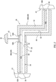
FIG. 2 is a partial schematic illustration of a fluid system for the engine system. -
FIGS. 3A-C are cross-sectional illustrations of a fluid flow circuit with various line damper arrangements. -
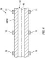
FIG. 4 is a partial side cutaway illustration of the fluid flow circuit with fastening devices mounting the line damper to a fluid line. -
FIG. 1 is a partial schematic illustration of asystem 10 for an engine of an aircraft. The aircraft may be an airplane, a rotorcraft (e.g., a helicopter), a drone (e.g., an unmanned aerial vehicle (UAV)) or any other manned or unmanned aerial vehicle or system. The aircraft engine may be a gas turbine engine, a rotary engine (e.g., a Wenkel engine), a reciprocating piston engine or any other type of internal combustion engine. Theengine system 10 ofFIG. 1 includes a fluid system 12 and one or more internal and/or peripheral components 14 of the aircraft engine. - The fluid system 12 is configured to service the one or more engine components 14. The fluid system 12 of
FIG. 1 , for example, is configured to deliver fluid to the engine components 14, where the fluid is used by the engine components 14 and/or subsequently distributed (e.g., sprayed, jetted or otherwise injected or directed) by the engine components 14 within the aircraft engine. For ease of description, the fluid system 12 may be described below as a fuel delivery system 16 for the aircraft engine and its engine components 14, and the fluid may be described below as fuel. The present disclosure, however, is not limited to such an exemplary fluid system application. The fluid system 12, for example, may alternatively deliver lubricant, coolant, hydraulic fluid and/or any other liquid fluid to the engine components 14 (e.g., at high pressure) to facilitate lubrication, cooling, actuation, etc. of the engine components 14. - The fluid system 12 of
FIG. 1 includes afluid reservoir 18, afluid pump 20, an upstreamfluid flow regulator 22, a downstreamfluid flow regulator 24 and afluid flow circuit 26. This fluid system 12, of course, may also include various other fluid system components, which are not shown inFIG. 1 for clarity of illustration. Examples of these other fluid system components include, but are not limited to, one or more filters, one or more sensors, one or more additional pumps, one or more additional flow regulators (e.g., valves or valve systems), one or more heat exchangers, and/or the like. - The
fluid reservoir 18 is configured to store a quantity of the fluid before, during and/or after engine system operation. Thefluid reservoir 18, for example, may be configured as or otherwise include a tank, a cylinder, a pressure vessel, a bladder or any other type of fluid storage container. Thefluid reservoir 18 ofFIG. 1 includes anoutlet 28 from an internal cavity within thefluid reservoir 18 for storing the fluid. - Each of the
fluid flow regulators fluid flow regulator fluid flow regulators fluid flow regulator 22, for example, may be configured as a throttle valve assembly with an internal solenoid valve. The downstreamfluid flow regulator 24 may be configured as a fuel control with one or more internal control valves. The present disclosure, however, is not limited to such exemplary flow regulator configurations. Each flow regulator valve may be configured to fully open, fully close and/or move to one or more (e.g., predefined or infinitely adjustable) intermediate positions to regulate the flow of the fluid through the respectivefluid flow regulator fluid flow regulators 22 and/or 24 may each be (e.g., directly) mounted to asupport structure 30 such as, but not limited to, an engine housing (e.g., a casing) for the aircraft engine. - The
flow circuit 26 is configured to fluidly couple thefluid reservoir 18 to the one or more engine components 14. Theflow circuit 26 ofFIG. 1 , for example, is arranged between and fluidly coupled to thereservoir outlet 28 and aninlet 32 into each engine component 14. Thisflow circuit 26 extends longitudinally from thereservoir outlet 28, sequentially through thefluid pump 20, the upstreamfluid flow regulator 22, the downstreamfluid flow regulator 24, to eachcomponent inlet 32. - The
flow circuit 26 ofFIG. 1 includes afluid line 34; e.g., a fuel line. Thisfluid line 34 is a rigid tube (e.g., a metal conduit, metal pipe, etc.) which fluidly couples the upstreamfluid flow regulator 22 to the downstreamfluid flow regulator 24. A longitudinalupstream end 36 of thefluid line 34 ofFIG. 1 , for example, is (e.g., directly) fluidly coupled to an outlet from the upstreamfluid flow regulator 22 by an upstream coupling; e.g., a threaded fluid fitting. A longitudinaldownstream end 38 of thefluid line 34 ofFIG. 1 is (e.g., directly) fluidly coupled to an inlet into the downstreamfluid flow regulator 24 by a downstream coupling; e.g., a threaded fluid fitting. Thefluid line 34 extends longitudinally along a centerline 40 from the lineupstream end 36 to the linedownstream end 38, defining a longitudinal length of thefluid line 34 along thecenterline 40 between the lineupstream end 36 and the linedownstream end 38. Theflow circuit 26 and itsfluid line 34 may be mounted to thesupport structure 30 by aline mount 42. This line mount 42 may be (e.g., directly) mechanically fastened or otherwise connected to thesupport structure 30. The line mount 42 projects out from thesupport structure 30 to thefluid line 34. A longitudinal intermediate portion of thefluid line 34 may be clamped onto and/or otherwise connected to and is supported by theline mount 42. The connection between theline mount 42 and thefluid line 34 may be a rigid connection or a compliant connection (e.g., through a damping element). - The engine components 14 may be any components of the aircraft engine which utilize and/or transfer the fluid during aircraft engine operation. For example, where the fluid system 12 is configured as the fuel delivery system 16 and where the fluid is fuel, one or more or all of the engine components 14 may be configured as fuel injectors 44 within a combustor section or an auxiliary thrust section of the aircraft engine. Each of these fuel injectors 44 is configured to inject or otherwise deliver fuel into an internal volume 46 (e.g., a combustion chamber or another section of a core flowpath) within the aircraft engine for subsequent combustion. The present disclosure, however, is not limited to such exemplary arrangement. One or more of the engine components 14, for example, may alternatively be configured as a fuel actuated device. Moreover, as discussed above, the fluid may alternatively be lubricant, coolant, hydraulic fluid and/or any other liquid fluid. Here, the engine components 14 may be configured as fluid delivery devices (e.g., injectors), actuators (e.g., hydraulic pistons) and/or components of the aircraft engine which utilize lubrication (e.g., bearings, gears, etc.) and/or cooling (or heating). The present disclosure, however, is not limited to the foregoing exemplary engine components.
- During operation of the
engine system 10, thefluid pump 20 directs (e.g., pumps) a quantity of the fluid from thefluid reservoir 18 through theflow circuit 26 to the engine components 14. Along theflow circuit 26, a flow of the fluid is regulated by thefluid flow regulators - During fluid flow regulation, the upstream
fluid flow regulator 22 and its valve may oscillate (e.g., slightly open and close) to maintain the flow of the fluid at a predetermined (or requested) fluid flowrate and/or fluid pressure, or within a predetermined (or requested) fluid flowrate range and/or fluid pressure range. This oscillation may induce (e.g., high frequency) pressure wave oscillations in the fluid flowing downstream of the upstreamfluid flow regulator 22 and, in particular, in the fluid flowing through thefluid line 34. Under certain conditions, a frequency of these pressure wave oscillations may be equal to or greater than one thousand five hundred hertz (1500 Hz). The frequency of the pressure wave oscillations, for example, may be between one thousand six hundred hertz (1600 Hz) and two thousand hertz (2000 Hz); e.g., equal to or about one thousand eight hundred hertz (1800 Hz). These pressure wave oscillations may locally increase a pressure of the fluid flowing within thefluid line 34. For example, where the fluid is directed into thefluid line 34 at a fluid pressure equal to or about one thousand one hundred pounds per square inch (1100 psi, about 7.6 MPa), the pressure wave oscillations may locally increase the fluid pressure to two thousand pounds per square inch (2000 psi, about 13.8 MPa), two thousand five hundred pounds per square inch (2500 psi, about 17.2 MPa), or even three thousand pounds per square inch (3000 psi, about 20.7 MPa). Thefluid line 34 may thereby be subject to relatively high stress load cycling, which can significantly reduce a service life of thefluid line 34. The present disclosure, of course, is not limited to such exemplary fluid pressures nor frequencies of the pressure wave oscillations. The fluid, for example, may alternatively be directed into thefluid line 34 at a pressure between eight hundred pounds per square inch (800 psi, about 5.5 MPa) and one thousand pounds per square inch (1000 psi, about 6.9 MPa), or greater than thousand pounds per square inch (1000 psi, about 6.9 MPa). In another example, the frequency of these pressure wave oscillations may be less than one thousand five hundred hertz (1500 Hz) such as between one thousand hertz (1000 Hz) and one thousand five hundred hertz (1500 Hz); e.g., one thousand one hundred hertz (1100 Hz). - Referring to
FIG. 2 , to reduce the stress loading on thefluid line 34, theflow circuit 26 ofFIG. 1 also includes one ormore vibration dampers fluid line 34. Each of these line dampers 48 is configured as or otherwise includes anelastomeric foam sleeve FIGS. 3A-C , each elastomeric foam sleeve 50 is configured as a tubular body formed byelastomeric foam 52 with multiple open-cell and/or closed cell pores 54. Theelastomeric foam 52 is constructed from an elastomeric material such as, but not limited to, silicone rubber, fluorocarbon rubber (e.g., Viton™ material), or ethylene propylene diene monomer (EPDM) rubber. Alternatively, the elastomeric material may be nitrile butadiene rubber (NBR), neoprene rubber or chloroprene rubber where, for example, sulfur can be tolerated. Thepores 54 within theelastomeric foam 52 are gas filled cavities, where the gas may be air or a pore forming gas used during manufacture of theelastomeric foam 52. - Referring to
FIG. 2 , eachelastomeric foam sleeve upstream end downstream end longitudinal length elastomeric foam sleeve centerline 40 between its sleeveupstream end downstream end FIGS. 3A-C , each elastomeric foam sleeve 50 extends radially (relative to the centerline 40) from a radialinner side 62 of the respective elastomeric foam sleeve 50 to a radialouter side 64 of the respective elastomeric foam sleeve 50, defining aradial thickness 66 of the respective elastomeric foam sleeve 50 between its sleeveinner side 62 and its sleeveouter side 64. Thissleeve thickness 66 may be uniform (the same) circumferentially about thecenterline 40 and/or longitudinally along thecenterline 40; see alsoFIG. 2 . Each elastomeric foam sleeve 50 extends circumferentially about (e.g., partially or completely around) thecenterline 40. The elastomeric foam sleeve 50 ofFIG. 3A , for example, extends completely circumferentially around thecenterline 40 providing that elastomeric foam sleeve 50 with a full-hoop body; e.g., a circumferentially uninterrupted body. The elastomeric foam sleeve 50 ofFIGS. 3B and 3C , by contrast, extends partially (e.g., at least 300°, 320° or 340°) circumferentially about thecenterline 40 between opposingcircumferential sides first side 68 ofFIGS. 3B and 3C is disposed circumferentially next to (e.g., adjacent) the sleevesecond side 70. In some embodiments, referring toFIG. 3B , the sleevefirst side 68 may circumferentially engage (e.g., abut against, contact, etc.) the sleevesecond side 70. In other embodiments, referring toFIG. 3C , the sleevefirst side 68 may be (e.g., slightly) circumferentially spaced from the sleevesecond side 70. A small gap, for example, may be formed by and extend circumferentially between the sleevefirst side 68 and the sleevesecond side 70. - Referring to
FIG. 2 , each line damper 48 and its elastomeric foam sleeve 50 is mounted to thefluid line 34. Thefluid line 34 ofFIG. 2 , for example, projects longitudinally through an inner bore of each elastomeric foam sleeve 50. Each elastomeric foam sleeve 50 extends longitudinally along thefluid line 34 between its respective line ends 56 and 58. Here, each elastomeric foam sleeve 50 is disposed radially next to and contacts (e.g., is abutted against, is pressed against, etc.) thefluid line 34 longitudinally along at least eighty percent (80%), ninety percent (90%) or a longitudinal entirety of its sleeve length 60. Referring toFIGS. 3A-C , each elastomeric foam sleeve 50 extends circumferentially about (e.g., partially or completely around) thefluid line 34. Here, each elastomeric foam sleeve 50 is disposed radially next to and contacts (e.g., is abutted against, is pressed against, etc.) thefluid line 34 at least three hundred degrees (300°), three hundred and twenty degrees (320°), or three hundred and forty degrees (340°) circumferentially around a circumference of thefluid line 34. The elastomeric foam sleeve 50 ofFIGS. 3A and 3B , in particular, is disposed radially next to and contacts thefluid line 34 along an entire circumference of thefluid line 34. In general, the radial contact between the elastomeric foam sleeve 50 and thefluid line 34 is longitudinally and/or circumferentially uninterrupted. However, it is contemplated one or more slight longitudinally and/or circumferentially interruptions may occur in the radial contact between the elastomeric foam sleeve 50 and thefluid line 34 where, for example, the elastomeric foam sleeve 50 follows a tight bend in thefluid line 34, etc. - Referring to
FIG. 2 , the upstreamelastomeric foam sleeve 50A is disposed longitudinally along thefluid line 34 and thecenterline 40 between the upstreamfluid flow regulator 22 and theline mount 42. The upstreamelastomeric foam sleeve 50A is thereby mounted to and covers an upstream portion of thefluid line 34. In particular, the sleeveupstream end 56A of the upstreamelastomeric foam sleeve 50A ofFIG. 2 is longitudinally next to, but (e.g., slightly) spaced from the upstreamfluid flow regulator 22. However, the sleeveupstream end 56A of the upstreamelastomeric foam sleeve 50A may alternatively longitudinally engage the upstreamfluid flow regulator 22. The sleevedownstream end 58A of the upstreamelastomeric foam sleeve 50A ofFIG. 2 is longitudinally next to, but (e.g., slightly) spaced from theline mount 42. However, the sleevedownstream end 58A of the upstreamelastomeric foam sleeve 50A may alternatively longitudinally engage theline mount 42. The upstreamelastomeric foam sleeve 50A, however, may still be discrete from (e.g., not a part of) theline mount 42. - The downstream
elastomeric foam sleeve 50B is disposed longitudinally along thefluid line 34 and thecenterline 40 between theline mount 42 and the downstreamfluid flow regulator 24. The downstreamelastomeric foam sleeve 50B is thereby mounted to and covers a downstream portion of thefluid line 34. In particular, the sleeveupstream end 56B of the downstreamelastomeric foam sleeve 50B ofFIG. 2 is longitudinally next to, but (e.g., slightly) spaced from theline mount 42. However, the sleeveupstream end 56B of the downstreamelastomeric foam sleeve 50B may alternatively longitudinally engage theline mount 42. The downstreamelastomeric foam sleeve 50B, however, may still be discrete from (e.g., not a part of) theline mount 42. The sleevedownstream end 58B of the downstreamelastomeric foam sleeve 50B ofFIG. 2 is longitudinally next to, but (e.g., slightly) spaced from the downstreamfluid flow regulator 24. However, the sleevedownstream end 58B of the downstreamelastomeric foam sleeve 50B may alternatively longitudinally engage the downstreamfluid flow regulator 24. - With the foregoing arrangement, the line dampers 48 and their elastomeric foam sleeves 50 are configured to damp the pressure wave oscillations travelling through the fluid in the
fluid line 34. The elastomeric foam sleeves 50, for example, may absorb vibrations and dissipate those vibrations through deformation (e.g., slight compression, expansions, bending, etc.) of theelastomeric foam 52 forming each respective elastomeric foam sleeve 50. The line dampers 48 and their elastomeric foam sleeves 50 may thereby reduce the stress loading on thefluid line 34 and increase the service life of thefluid line 34. - In some embodiments, each elastomeric foam sleeve 50 may be pressed radially against the
fluid line 34. For example, there may be a tight fit between each elastomeric foam sleeve 50 and thefluid line 34 where an outer radius of thefluid line 34 is greater than an inner radius of each elastomeric foam sleeve 50 prior to mounting onto thefluid line 34. In addition or alternatively, referring toFIG. 4 , one or more fastening devices 72 (schematically shown) may be used to press (e.g., squeeze, compress, etc.) each elastomeric foam sleeve 50 against thefluid line 34. Examples of thefastening devices 72 include, but are not limited to, clamps, zip ties, cords, tape, and the like. - While the elastomeric foam sleeves 50 may be generally described above with reference to a relatively high frequency system and/or a relatively high pressure system, the present disclosure is not limited thereto. It is contemplated, for example, the elastomeric foam sleeve(s) 50 may also provide a damping benefit for a relatively low frequency system and/or a relatively low pressure systems as well.
- While various embodiments of the present disclosure have been described, it will be apparent to those of ordinary skill in the art that many more embodiments and implementations are possible within the scope of the disclosure. For example, the present disclosure as described herein includes several aspects and embodiments that include particular features. Although these features may be described individually, it is within the scope of the present disclosure that some or all of these features may be combined with any one of the aspects and remain within the scope of the disclosure. Accordingly, the present disclosure is not to be restricted except in light of the attached claims and their equivalents.
Claims (15)
- A method of operation, comprising:directing a fluid through a fluid line (34) servicing a component (14) of an aircraft engine, wherein pressure wave oscillations travel through the fluid within the fluid line (34) at a frequency equal to or greater than one thousand hertz during the directing of the fluid; anddamping the pressure wave oscillations traveling through the fluid within the fluid line (34) using an elastomeric foam sleeve (50A) in contact with the fluid line (34), the elastomeric foam sleeve (50A) extending longitudinally along and circumscribing the fluid line (34).
- The method of claim 1, wherein the fluid comprises a liquid.
- The method of claim 1 or 2, wherein the frequency is equal to or greater than one thousand eight hundred hertz.
- The method of claim 1, 2 or 3, wherein the fluid is directed through the fluid line (34) at a pressure equal to or greater than one thousand pounds per square inch (about 6.9 MPa).
- The method of any preceding claim, wherein the fluid line (34) is fluidly coupled to and downstream of a flow regulator (22), and the pressure wave oscillations are generated by operation of the flow regulator (22),
wherein, optionally, the flow regulator (22) comprises a solenoid valve. - The method of claim 5, wherein:the flow regulator is a first flow regulator (22), and the fluid line (34) is fluidly coupled to and upstream of a second flow regulator (24); andthe fluid line (34) extends longitudinally from a first coupling between the fluid line (34) and the first flow regulator (22) and a second coupling between the fluid line (34) and the second flow regulator (24).
- The method of any preceding claim, wherein:the elastomeric foam sleeve (50A) has a longitudinal length (60A); andthe elastomeric foam sleeve (50A) contacts the fluid line (34) longitudinally along at least eighty-percent of the longitudinal length (60A).
- The method of any preceding claim, wherein the elastomeric foam sleeve (50A) contacts the fluid line (34) at least three hundred degrees circumferentially around the fluid line (34).
- The method of any preceding claim, wherein the elastomeric foam sleeve (50A) has a full-hoop tubular body.
- The method of any preceding claim, wherein:the elastomeric foam sleeve (50A) extends circumferentially about the fluid line (34) between a first circumferential side (68) of the elastomeric foam sleeve (50A) and a second circumferential side (70) of the elastomeric foam sleeve (50A); andthe first circumferential side (68) of the elastomeric foam sleeve (50A) is circumferentially next to the second circumferential side (70) of the elastomeric foam sleeve (50A),wherein, optionally, the first circumferential side (68) of the elastomeric foam sleeve (50A) is abutted circumferentially against the second circumferential side (70) of the elastomeric foam sleeve (50A).
- The method of any preceding claim, wherein:the elastomeric foam sleeve (50A) comprises silicone rubber; and/orthe aircraft engine comprises a gas turbine engine.
- The method of any preceding claim, wherein:the fluid line (34) is mounted to a case of the aircraft engine by a mount (42); andthe elastomeric foam sleeve (50A) is discrete from the mount (42), wherein, optionally, the elastomeric foam sleeve (50A) is spaced longitudinally from the mount (42) along the fluid line (34) by a gap.
- The method of any preceding claim, wherein:the fluid comprises fuel;the component (14) comprises a fuel injector in the aircraft engine; andthe directing of the fluid comprises directing the fluid through the fluid line (34) to the fuel injector for injection into a combustion volume within the aircraft engine.
- A method of operation, comprising:directing a liquid fluid through a flow regulator (22) into a fluid line (34), the fluid line (34) included as part of a fluid system (12) of a gas turbine engine;regulating flow of the liquid fluid through the flow regulator (22), the regulating of the flow of the liquid fluid through the flow regulator (22) inducing pressure wave oscillations in the liquid fluid within the fluid line (34); anddamping the pressure wave oscillations in the liquid fluid within the fluid line (34) using a line damper (48A) abutted radially against the fluid line (34), the line damper (48A) extending longitudinally along and circumscribing the fluid line (34), and the line damper (48A) comprising an elastomeric foam (52),wherein, optionally:the pressure wave oscillations have a frequency equal to or greater than one thousand hertz during the directing of the regulating of the flow of the liquid fluid; andthe liquid fluid is directed through the fluid line (34) at a pressure equal to or greater than one-thousand pounds per square inch (about 6.9 MPa).
- A system (10) for a gas turbine engine, comprising:a gas turbine engine component (14);a fluid system (12) configured to deliver fluid to the gas turbine engine component (14), the fluid system (12) including an upstream flow regulator (22), a downstream flow regulator (24) and a fluid line (34) fluidly coupling the upstream flow regulator (22) to the downstream flow regulator (24), the upstream flow regulator (22) configured to regulate flow of the fluid into the fluid line (34) to the downstream flow regulator (24), wherein the regulating of the flow of the fluid through the flow regulator (22) induces pressure wave oscillations in the fluid within the fluid line (34) at a frequency equal to or greater than one thousand hertz; andan elastomeric foam sleeve (50A) configured to damp the pressure wave oscillation in the fluid within the fluid line (34), the elastomeric foam sleeve (50A) contacting the fluid line (34), and the elastomeric foam sleeve (50A) extending longitudinally along and circumscribing the fluid line (34).
Applications Claiming Priority (1)
| Application Number | Priority Date | Filing Date | Title |
|---|---|---|---|
| US18/383,362 US20250129871A1 (en) | 2023-10-24 | 2023-10-24 | Damped fluid line for aircraft engine |
Publications (1)
| Publication Number | Publication Date |
|---|---|
| EP4545757A1 true EP4545757A1 (en) | 2025-04-30 |
Family
ID=92538940
Family Applications (1)
| Application Number | Title | Priority Date | Filing Date |
|---|---|---|---|
| EP24196223.2A Pending EP4545757A1 (en) | 2023-10-24 | 2024-08-23 | Damped fluid line for aircraft engine |
Country Status (2)
| Country | Link |
|---|---|
| US (1) | US20250129871A1 (en) |
| EP (1) | EP4545757A1 (en) |
Citations (4)
| Publication number | Priority date | Publication date | Assignee | Title |
|---|---|---|---|---|
| DE69906868T2 (en) * | 1998-05-30 | 2003-11-13 | Rolls-Royce Plc, London | Fuel injection |
| US20040060609A1 (en) * | 2002-05-31 | 2004-04-01 | Fatato Francis B. | Monolayer foamed corrugated sleeve |
| DE102013109205A1 (en) * | 2012-09-10 | 2014-03-13 | General Electric Company | Metal foam for circumferential support in high temperature / vibration applications |
| US20180058404A1 (en) * | 2016-08-29 | 2018-03-01 | Parker-Hannifin Corporation | Fuel injector assembly with wire mesh damper |
Family Cites Families (14)
| Publication number | Priority date | Publication date | Assignee | Title |
|---|---|---|---|---|
| US4314621A (en) * | 1979-03-07 | 1982-02-09 | Caterpillar Tractor Co. | Fluidborne noise attenuator |
| JP2006097716A (en) * | 2004-09-28 | 2006-04-13 | Tokai Rubber Ind Ltd | High pressure resistant vibration absorbing hose and manufacturing method thereof |
| US20070292647A1 (en) * | 2006-06-16 | 2007-12-20 | Princell Charles M | Lap and seam seal closure system for foam pipe insulation |
| US20090178723A1 (en) * | 2008-01-11 | 2009-07-16 | Joseph Cioffi | Supportive apparatus for piping and similar structures and method for the use thereof |
| FR2930590B1 (en) * | 2008-04-23 | 2013-05-31 | Snecma | TURBOMACHINE HOUSING HAVING A DEVICE WHICH PREVENTS INSTABILITY IN CONTACT BETWEEN THE CARTER AND THE ROTOR |
| US8701848B2 (en) * | 2011-03-29 | 2014-04-22 | Gm Global Technology Operations | Sleeve damper assembly |
| WO2013165617A1 (en) * | 2012-05-01 | 2013-11-07 | Exxonmobil Upstream Research Company | Systems for decreasing abrasive wear in a pipeline configured to transfer a slurry |
| US9431810B2 (en) * | 2012-07-11 | 2016-08-30 | The Boeing Company | Line mounting system |
| US20150079316A1 (en) * | 2013-09-17 | 2015-03-19 | Nomaco Inc. | Elongated fasteners for retaining insulation wraps around elongated containers, such as pipes, subject to temperature fluctuations, and related components and methods |
| US10690267B2 (en) * | 2018-07-16 | 2020-06-23 | Raytheon Technologies Corporation | Adjustable holding assembly |
| US11958587B2 (en) * | 2020-03-30 | 2024-04-16 | Embraer S.A. | Molded aircraft wiring and/or tubing support brackets |
| US10968837B1 (en) * | 2020-05-14 | 2021-04-06 | Bj Energy Solutions, Llc | Systems and methods utilizing turbine compressor discharge for hydrostatic manifold purge |
| US12170390B2 (en) * | 2022-02-21 | 2024-12-17 | General Electric Company | Systems and method of operating a fuel cell assembly, a gas turbine engine, or both |
| US11852048B2 (en) * | 2022-04-14 | 2023-12-26 | Caterpillar Inc. | Gas admission valve (GAV) assembly and system and method thereof |
-
2023
- 2023-10-24 US US18/383,362 patent/US20250129871A1/en active Pending
-
2024
- 2024-08-23 EP EP24196223.2A patent/EP4545757A1/en active Pending
Patent Citations (4)
| Publication number | Priority date | Publication date | Assignee | Title |
|---|---|---|---|---|
| DE69906868T2 (en) * | 1998-05-30 | 2003-11-13 | Rolls-Royce Plc, London | Fuel injection |
| US20040060609A1 (en) * | 2002-05-31 | 2004-04-01 | Fatato Francis B. | Monolayer foamed corrugated sleeve |
| DE102013109205A1 (en) * | 2012-09-10 | 2014-03-13 | General Electric Company | Metal foam for circumferential support in high temperature / vibration applications |
| US20180058404A1 (en) * | 2016-08-29 | 2018-03-01 | Parker-Hannifin Corporation | Fuel injector assembly with wire mesh damper |
Also Published As
| Publication number | Publication date |
|---|---|
| US20250129871A1 (en) | 2025-04-24 |
Similar Documents
| Publication | Publication Date | Title |
|---|---|---|
| US6948479B1 (en) | Inline pulsation damper system | |
| US7802560B2 (en) | Fuel injector mounting assembly for an aircraft engine fuel delivery system | |
| CN101405496A (en) | Opposed piston engine | |
| JP2003035239A (en) | High pressure fuel supply pump | |
| CN101111665A (en) | Large two-stroke diesel engine with hydraulically actuated exhaust valve | |
| JP5345152B2 (en) | Fuel pump system, method of operating fuel pump system, and fuel injection system including fuel pump system | |
| WO2018164026A1 (en) | High-pressure pump | |
| EP2597286A2 (en) | Machined springs for injector applications | |
| JP6708238B2 (en) | High pressure pump | |
| EP4545757A1 (en) | Damped fluid line for aircraft engine | |
| US20160222958A1 (en) | System and method for priming a pump | |
| CN104981605B (en) | valve | |
| WO2019065973A1 (en) | High-pressure pump | |
| WO2016122826A1 (en) | Pumping mechanism with plunger | |
| CN111512039A (en) | High-pressure fuel pump | |
| WO2019065992A1 (en) | High-pressure pump | |
| JP6809520B2 (en) | High pressure pump | |
| JP6747482B2 (en) | High pressure pump | |
| CN216866869U (en) | Diesel oil delivery system for diesel engine and diesel engine | |
| JP7180230B2 (en) | high pressure pump | |
| US10871084B2 (en) | Mount assembly | |
| JP2008190508A (en) | Fuel rail for internal combustion engine and fuel supply device | |
| CN105556111B (en) | Fluid Delivery Systems for Fluids | |
| CA3105244A1 (en) | Turbocharger lubrication system for a two-stroke engine | |
| US12480596B2 (en) | Multi-function fluid control valve |
Legal Events
| Date | Code | Title | Description |
|---|---|---|---|
| PUAI | Public reference made under article 153(3) epc to a published international application that has entered the european phase |
Free format text: ORIGINAL CODE: 0009012 |
|
| STAA | Information on the status of an ep patent application or granted ep patent |
Free format text: STATUS: THE APPLICATION HAS BEEN PUBLISHED |
|
| AK | Designated contracting states |
Kind code of ref document: A1 Designated state(s): AL AT BE BG CH CY CZ DE DK EE ES FI FR GB GR HR HU IE IS IT LI LT LU LV MC ME MK MT NL NO PL PT RO RS SE SI SK SM TR |
|
| STAA | Information on the status of an ep patent application or granted ep patent |
Free format text: STATUS: REQUEST FOR EXAMINATION WAS MADE |
|
| 17P | Request for examination filed |
Effective date: 20251030 |