EP2597286A2 - Machined springs for injector applications - Google Patents
Machined springs for injector applications Download PDFInfo
- Publication number
- EP2597286A2 EP2597286A2 EP20120190664 EP12190664A EP2597286A2 EP 2597286 A2 EP2597286 A2 EP 2597286A2 EP 20120190664 EP20120190664 EP 20120190664 EP 12190664 A EP12190664 A EP 12190664A EP 2597286 A2 EP2597286 A2 EP 2597286A2
- Authority
- EP
- European Patent Office
- Prior art keywords
- spring
- machined
- channels
- annular wall
- liquid
- Prior art date
- Legal status (The legal status is an assumption and is not a legal conclusion. Google has not performed a legal analysis and makes no representation as to the accuracy of the status listed.)
- Granted
Links
- 239000007788 liquid Substances 0.000 claims abstract description 69
- 239000000446 fuel Substances 0.000 claims description 16
- 238000011144 upstream manufacturing Methods 0.000 claims description 9
- 239000012530 fluid Substances 0.000 claims description 3
- 238000000034 method Methods 0.000 description 8
- 238000003466 welding Methods 0.000 description 7
- 238000004804 winding Methods 0.000 description 4
- 238000000137 annealing Methods 0.000 description 2
- 230000006835 compression Effects 0.000 description 2
- 238000007906 compression Methods 0.000 description 2
- 230000001105 regulatory effect Effects 0.000 description 2
- 238000004904 shortening Methods 0.000 description 2
- 230000001174 ascending effect Effects 0.000 description 1
- 238000007796 conventional method Methods 0.000 description 1
- 230000000694 effects Effects 0.000 description 1
- 238000009760 electrical discharge machining Methods 0.000 description 1
- 238000010438 heat treatment Methods 0.000 description 1
- 238000009434 installation Methods 0.000 description 1
- 238000004519 manufacturing process Methods 0.000 description 1
- 238000003801 milling Methods 0.000 description 1
- 238000012986 modification Methods 0.000 description 1
- 230000004048 modification Effects 0.000 description 1
- 230000036316 preload Effects 0.000 description 1
- 238000009877 rendering Methods 0.000 description 1
- 239000007921 spray Substances 0.000 description 1
- 229910001220 stainless steel Inorganic materials 0.000 description 1
- 239000010935 stainless steel Substances 0.000 description 1
Images


Classifications
-
- F—MECHANICAL ENGINEERING; LIGHTING; HEATING; WEAPONS; BLASTING
- F02—COMBUSTION ENGINES; HOT-GAS OR COMBUSTION-PRODUCT ENGINE PLANTS
- F02C—GAS-TURBINE PLANTS; AIR INTAKES FOR JET-PROPULSION PLANTS; CONTROLLING FUEL SUPPLY IN AIR-BREATHING JET-PROPULSION PLANTS
- F02C7/00—Features, components parts, details or accessories, not provided for in, or of interest apart form groups F02C1/00 - F02C6/00; Air intakes for jet-propulsion plants
- F02C7/22—Fuel supply systems
- F02C7/232—Fuel valves; Draining valves or systems
-
- B—PERFORMING OPERATIONS; TRANSPORTING
- B01—PHYSICAL OR CHEMICAL PROCESSES OR APPARATUS IN GENERAL
- B01D—SEPARATION
- B01D29/00—Filters with filtering elements stationary during filtration, e.g. pressure or suction filters, not covered by groups B01D24/00 - B01D27/00; Filtering elements therefor
- B01D29/11—Filters with filtering elements stationary during filtration, e.g. pressure or suction filters, not covered by groups B01D24/00 - B01D27/00; Filtering elements therefor with bag, cage, hose, tube, sleeve or like filtering elements
- B01D29/111—Making filtering elements
-
- B—PERFORMING OPERATIONS; TRANSPORTING
- B05—SPRAYING OR ATOMISING IN GENERAL; APPLYING FLUENT MATERIALS TO SURFACES, IN GENERAL
- B05B—SPRAYING APPARATUS; ATOMISING APPARATUS; NOZZLES
- B05B1/00—Nozzles, spray heads or other outlets, with or without auxiliary devices such as valves, heating means
- B05B1/14—Nozzles, spray heads or other outlets, with or without auxiliary devices such as valves, heating means with multiple outlet openings; with strainers in or outside the outlet opening
-
- B—PERFORMING OPERATIONS; TRANSPORTING
- B05—SPRAYING OR ATOMISING IN GENERAL; APPLYING FLUENT MATERIALS TO SURFACES, IN GENERAL
- B05B—SPRAYING APPARATUS; ATOMISING APPARATUS; NOZZLES
- B05B15/00—Details of spraying plant or spraying apparatus not otherwise provided for; Accessories
- B05B15/40—Filters located upstream of the spraying outlets
-
- F—MECHANICAL ENGINEERING; LIGHTING; HEATING; WEAPONS; BLASTING
- F02—COMBUSTION ENGINES; HOT-GAS OR COMBUSTION-PRODUCT ENGINE PLANTS
- F02C—GAS-TURBINE PLANTS; AIR INTAKES FOR JET-PROPULSION PLANTS; CONTROLLING FUEL SUPPLY IN AIR-BREATHING JET-PROPULSION PLANTS
- F02C9/00—Controlling gas-turbine plants; Controlling fuel supply in air- breathing jet-propulsion plants
- F02C9/26—Control of fuel supply
- F02C9/28—Regulating systems responsive to plant or ambient parameters, e.g. temperature, pressure, rotor speed
- F02C9/285—Mechanical command devices linked to the throttle lever
-
- F—MECHANICAL ENGINEERING; LIGHTING; HEATING; WEAPONS; BLASTING
- F02—COMBUSTION ENGINES; HOT-GAS OR COMBUSTION-PRODUCT ENGINE PLANTS
- F02M—SUPPLYING COMBUSTION ENGINES IN GENERAL WITH COMBUSTIBLE MIXTURES OR CONSTITUENTS THEREOF
- F02M61/00—Fuel-injectors not provided for in groups F02M39/00 - F02M57/00 or F02M67/00
- F02M61/16—Details not provided for in, or of interest apart from, the apparatus of groups F02M61/02 - F02M61/14
- F02M61/18—Injection nozzles, e.g. having valve seats; Details of valve member seated ends, not otherwise provided for
-
- F—MECHANICAL ENGINEERING; LIGHTING; HEATING; WEAPONS; BLASTING
- F02—COMBUSTION ENGINES; HOT-GAS OR COMBUSTION-PRODUCT ENGINE PLANTS
- F02M—SUPPLYING COMBUSTION ENGINES IN GENERAL WITH COMBUSTIBLE MIXTURES OR CONSTITUENTS THEREOF
- F02M61/00—Fuel-injectors not provided for in groups F02M39/00 - F02M57/00 or F02M67/00
- F02M61/16—Details not provided for in, or of interest apart from, the apparatus of groups F02M61/02 - F02M61/14
- F02M61/20—Closing valves mechanically, e.g. arrangements of springs or weights or permanent magnets; Damping of valve lift
-
- F—MECHANICAL ENGINEERING; LIGHTING; HEATING; WEAPONS; BLASTING
- F16—ENGINEERING ELEMENTS AND UNITS; GENERAL MEASURES FOR PRODUCING AND MAINTAINING EFFECTIVE FUNCTIONING OF MACHINES OR INSTALLATIONS; THERMAL INSULATION IN GENERAL
- F16F—SPRINGS; SHOCK-ABSORBERS; MEANS FOR DAMPING VIBRATION
- F16F1/00—Springs
- F16F1/02—Springs made of steel or other material having low internal friction; Wound, torsion, leaf, cup, ring or the like springs, the material of the spring not being relevant
- F16F1/04—Wound springs
- F16F1/042—Wound springs characterised by the cross-section of the wire
-
- F—MECHANICAL ENGINEERING; LIGHTING; HEATING; WEAPONS; BLASTING
- F23—COMBUSTION APPARATUS; COMBUSTION PROCESSES
- F23K—FEEDING FUEL TO COMBUSTION APPARATUS
- F23K5/00—Feeding or distributing other fuel to combustion apparatus
- F23K5/02—Liquid fuel
- F23K5/14—Details thereof
-
- F—MECHANICAL ENGINEERING; LIGHTING; HEATING; WEAPONS; BLASTING
- F23—COMBUSTION APPARATUS; COMBUSTION PROCESSES
- F23K—FEEDING FUEL TO COMBUSTION APPARATUS
- F23K5/00—Feeding or distributing other fuel to combustion apparatus
- F23K5/02—Liquid fuel
- F23K5/14—Details thereof
- F23K5/18—Cleaning or purging devices, e.g. filters
-
- F—MECHANICAL ENGINEERING; LIGHTING; HEATING; WEAPONS; BLASTING
- F23—COMBUSTION APPARATUS; COMBUSTION PROCESSES
- F23R—GENERATING COMBUSTION PRODUCTS OF HIGH PRESSURE OR HIGH VELOCITY, e.g. GAS-TURBINE COMBUSTION CHAMBERS
- F23R3/00—Continuous combustion chambers using liquid or gaseous fuel
- F23R3/28—Continuous combustion chambers using liquid or gaseous fuel characterised by the fuel supply
-
- F—MECHANICAL ENGINEERING; LIGHTING; HEATING; WEAPONS; BLASTING
- F05—INDEXING SCHEMES RELATING TO ENGINES OR PUMPS IN VARIOUS SUBCLASSES OF CLASSES F01-F04
- F05D—INDEXING SCHEME FOR ASPECTS RELATING TO NON-POSITIVE-DISPLACEMENT MACHINES OR ENGINES, GAS-TURBINES OR JET-PROPULSION PLANTS
- F05D2260/00—Function
- F05D2260/30—Retaining components in desired mutual position
- F05D2260/38—Retaining components in desired mutual position by a spring, i.e. spring loaded or biased towards a certain position
-
- F—MECHANICAL ENGINEERING; LIGHTING; HEATING; WEAPONS; BLASTING
- F05—INDEXING SCHEMES RELATING TO ENGINES OR PUMPS IN VARIOUS SUBCLASSES OF CLASSES F01-F04
- F05D—INDEXING SCHEME FOR ASPECTS RELATING TO NON-POSITIVE-DISPLACEMENT MACHINES OR ENGINES, GAS-TURBINES OR JET-PROPULSION PLANTS
- F05D2260/00—Function
- F05D2260/50—Kinematic linkage, i.e. transmission of position
- F05D2260/52—Kinematic linkage, i.e. transmission of position involving springs
-
- F—MECHANICAL ENGINEERING; LIGHTING; HEATING; WEAPONS; BLASTING
- F23—COMBUSTION APPARATUS; COMBUSTION PROCESSES
- F23K—FEEDING FUEL TO COMBUSTION APPARATUS
- F23K2300/00—Pretreatment and supply of liquid fuel
- F23K2300/20—Supply line arrangements
- F23K2300/202—Filtering
-
- Y—GENERAL TAGGING OF NEW TECHNOLOGICAL DEVELOPMENTS; GENERAL TAGGING OF CROSS-SECTIONAL TECHNOLOGIES SPANNING OVER SEVERAL SECTIONS OF THE IPC; TECHNICAL SUBJECTS COVERED BY FORMER USPC CROSS-REFERENCE ART COLLECTIONS [XRACs] AND DIGESTS
- Y10—TECHNICAL SUBJECTS COVERED BY FORMER USPC
- Y10T—TECHNICAL SUBJECTS COVERED BY FORMER US CLASSIFICATION
- Y10T137/00—Fluid handling
- Y10T137/794—With means for separating solid material from the fluid
Definitions
- the present invention relates to injectors, and more particularly to springs used to bias injector components.
- Traditional springs are used in a variety of applications in injectors and nozzles, such as fuel injectors for gas turbine engines.
- Exemplary uses of springs in conventional injectors include use in biasing fuel strainers into position, biasing valve hold down components away from external injector walls, biasing scheduling valve components, and the like.
- Traditional springs in such applications can suffer from loss of spring force, can be difficult to assemble, add to part count, and take up considerable space.
- traditional wave springs used to bias valve components away from injector walls can loose their spring due to heat from welding operations on adjacent components. The welding heat can anneal the spring and thereby render the spring ineffective.
- the subject invention is directed to a new and useful machined spring for injector applications.
- the machined spring includes opposed first and second spring bases separated apart along a longitudinal axis.
- a spring body connects the first and second spring bases.
- the spring body includes a generally annular wall with a plurality of spring channels defined therethrough, such as machined channels.
- the plurality of spring channels includes first and second helical spring channels.
- the helical spring channels wind in counter-rotational directions around the annular wall for uniform spring stiffness and reduced buckling of the spring body to one side under a substantially axial load.
- At least one of the spring bases can include a liquid strainer.
- the liquid strainer can include a bulkhead separating a flow passage within the generally annular wall from a flow passage within the liquid strainer, wherein a plurality of bores are defined through the liquid strainer for passage of liquid from inside the generally annular wall through the bores and around the bulkhead to the exterior of a strainer mesh for straining liquid passing through the mesh into the flow passage within the liquid strainer.
- the liquid strainer can include a circumferential land extending outward from an upstream portion of the liquid strainer with a plurality of axial channels therethrough for passage of liquid out from inside the generally annular wall through the helical spring channels, through the axial channels to the exterior of a strainer mesh for straining liquid passing through the mesh into the flow passage within the liquid strainer.
- At least one of the helical spring channels can include a radial aperture configured to permit uninterrupted liquid flow therethrough even when the helical spring channels are fully compressed axially.
- At least one of the spring bases can include a valve cross-over configured and adapted to allow flow of liquid out from inside the generally annular wall through the valve cross-over for use in a valve.
- at least one of the spring bases includes a valve hold down component with an axially extending standoff configured to separate valve components within the generally annular wall from injector components outside the generally annular wall.
- the spring channels are circumferential spring channels, wherein each circumferential spring channel winds circumferentially around a portion of the annular wall to provide flexibility in the direction of the longitudinal axis and stiffness in a torque direction around the longitudinal axis circumferentially.
- the axially extending wall sections between channel ends of each axially adjacent pair of channels can be circumferentially offset from one another, by about 90° for example, for increasing uniformity in longitudinal flexibility of the annular wall.
- Each channel end can include an enlarged terminus for reducing stress concentrations.
- the invention also provides a fuel injector.
- the fuel injector includes an injector body having an upstream inlet end and opposed downstream end for injecting fluids therefrom.
- a machined spring as described above, is mounted between the upstream inlet and downstream ends of the injector body.
- the machined spring can include a liquid strainer as described above for straining liquids flowing through the injector body.
- a valve is mounted in the injector body to regulate liquid flow therethrough.
- the machined spring can include a valve cross-over mounted in the valve to allow flow of liquid out from inside the generally annular wall through the valve cross-over under a predetermined pressure range applied at the inlet end of the injector body.
- the injector can include a valve mounted in the injector body to regulate liquid flow therethrough.
- At least one of the spring bases of the machined spring includes a valve hold down component as described above with the axially extending standoff separating the valve within the generally annular wall from injector components outside the generally annular wall.
- each machined spring channel is a circumferential spring channel as described above, wherein the first spring base is mounted to the inlet end of the injector body.
- the second spring base is mounted to a feed arm of the injector.
- a liquid conduit extends through the annular wall.
- the machined spring is configured and adapted to accommodate differential thermal expansion of the feed arm and liquid conduit and to provide stiffness to the inlet end of the injector body in torsion.
- FIG. 1 a partial view of an exemplary embodiment of a machined spring in accordance with the invention is shown in Fig. 1 and is designated generally by reference character 100.
- Other embodiments of machined springs in accordance with the invention, or aspects thereof, are provided in Figs. 2-24 , as will be described.
- the systems and methods of the invention can be used to improve spring performance, reduce part count, reduce part size, and to simplify assembly and manufacture, for example in fuel injectors for gas turbine engines.
- Machined spring 100 includes a spring portion 102 and a liquid strainer 104 integral with spring portion 102.
- Figs. 1 and 2 show the spring portion 102 and integral liquid strainer 104 from upstream and downstream perspectives, respectively.
- Fig. 3 shows spring portion 102 including opposed first and second spring bases 106 and 108 separated apart along a longitudinal axis A.
- a spring body 110 connects the first and second spring bases 106 and 108.
- Spring body 110 includes a generally annular wall with two helical spring channels 112 and 114 defined therethrough.
- Spring channels 112 and 114 are machined channels which can be formed in the annular wall by a milling process, electrical discharge machining, a laser process, or the like.
- Spring channels 112 and 114 wind in counter-rotational directions around the annular wall. Said another way, spring channel 114 winds in a clockwise direction ascending around axis A as oriented in Fig. 3 , and spring channel 112 winds in a counter-clockwise direction.
- Having separate spring channels wound in opposite directions advantageously provides uniform spring stiffness and reduces the tendency for buckling of spring body 110 to one side under a substantially axial load when compared with helical springs having only one winding direction.
- spring base 108 includes liquid strainer 104.
- Liquid strainer 104 includes a bulkhead 116 separating a flow passage 118 within the annular wall of spring body 110 from a flow passage 120 within liquid strainer 104.
- a plurality of bores 122 are defined through liquid strainer 104 for passage of liquid from passage 118 inside the generally annular wall, through bores 122, and around bulkhead 116 to the exterior of a strainer mesh 124 for straining liquid passing through mesh 124 and strainer bores 125 into flow passage 120 within liquid strainer 104.
- This flow path is generally indicated by the heavy arrows in Fig. 4 .
- Mesh 124 is not shown in Figs. 1-2 to avoid obscuring underlying strainer structure.
- the largely axial flow, with liquid moving from external of strainer mesh 124 into the axial flow path, is advantageous because external pressure on a strainer allows for high burst pressure compared to traditional strainer configurations.
- Machined spring 100 is compressed so that liquid strainer 104 can be secured, e.g., bottomed, in a conduit 150 which can run between upstream and downstream ends of an injector, for example.
- the internal thread 152 aids in removal of strainer 104 for service or replacement.
- Outer o-ring 154 provides a seal to catch debris when strainer 104 is removed for service, and provides a trim orifice 158 for regulating flow. Having the spring and strainer integrated together reduces difficulties during assembly arising from a separate spring.
- Machined spring 200 has a spring portion 202 and liquid strainer 204 much as described above but with a different flow path.
- Machined spring 200 includes a circumferential land 217 extending outward from an upstream portion of liquid strainer 204 with a plurality of axial channels 219 therethrough.
- the flow path for straining liquid starts inside passage 218, from which liquid flows out through the helical spring channels 212 and 214, around bulkhead 216 through the axial channels 219 to the exterior of a strainer mesh 224 (which is only shown in Fig.
- each of the helical spring channels 212 and 214 includes a radial aperture 215, which are indicated in Fig. 7 . Due to the relatively large size of radial apertures 215 compared to spring channels 212 and 214, even if spring channels 212 and 214 are compressed axially, radial apertures 215 permit uninterrupted liquid flow therethrough.
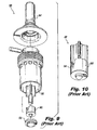
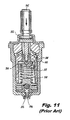
- a prior art injector 300 is shown, in which two liquid flow circuits are provided. Fuel entering inlet 302 can pass through pilot circuit 304 to be discharged from pilot nozzle 306, shown in Fig. 11 . As pressure at inlet 302 increases, the pressure on plunger 308, shown in Fig. 9 , provides increasing force to compress spring 310, which is shown in Fig. 11 . As plunger 308 moves farther into chamber 312, more and more of scheduling feature 314, shown in Fig. 10 , opens into main circuit 312, allowing an increase of liquid flow through main circuit 312 to issue from main nozzle 316. Due to the shape of scheduling feature 314, the greater the pressure at inlet 302, the greater the flow will be passing through main circuit 312. Flow paths for the main and pilot circuits 312 and 304 are indicated schematically with heavy arrows in Fig. 11 .
- an exemplary embodiment of an injector 400 is shown, which utilizes a machined spring 401.
- the basic valve flow regulation of injector 400 is similar to that described above for injector 300, including the uses of inlet 402 shown in Fig. 12 , main and pilot circuits 412 and 404 shown in Fig. 14 , plunger 408 with scheduling feature 414 shown in Fig. 13 , and main and pilot nozzles 416 and 406 shown in Fig. 14 .
- machined spring 401 offers certain advantages over traditional spring 310.
- machined spring 401 includes first and second spring bases 418 and 420 connected by a spring body 422 with two counter-winding helical spring channels 424 and 426 defined therethrough, as shown in Fig. 15 .
- helical spring channels 424 and 426 are stretched in a predetermined manner, extending scheduling feature 414 further into main circuit 412.
- the spring constant and desired flow scheduling must be matched for each given application.
- Liquid from inlet 402 reaches both pilot and main circuits 404 and 412 by passing from within the generally annular wall of spring body 422 out by way of valve cross-over 428, which is formed in spring base 420 as shown in Figs. 12-13 .
- Flow paths for the main and pilot circuits 412 and 404 are indicated schematically with heavy arrows in Fig. 14 .
- Plunger 408 with scheduling feature 414 form a scheduling valve member
- spring base 420 includes a peg 430 for mounting the scheduling valve member to machined spring 401.
- Stop 436 identified in Fig. 14 , provides a mechanical stop to prevent excessive inward travel of plunger 408.
- the length of injector 400 can be shortened, including shortening stop 436 without reducing the stroke length for plunger 408. Shortening injector 400 can advantageously reduce its weight and envelope size.
- valve retainer 332 Three items, namely valve retainer 332, spring seat 334, and spring 310, all shown in Fig. 11 , can essentially be replaced by machined spring 401. Due to the counter-winding of helical spring channels 424 and 426, buckling to one side as in spring 310 is reduced or eliminated, increasing the wear life of the moving parts in injector 400. In short, advantages of machined spring 401 over traditional spring 310 include reduced part count, reduced bearing surfaces for buckling issues, reduced need for hardened valve components (e.g., stainless steel valve components and heat treatment therefore, such as in typical 400SS valve components), and reduced valve envelope size and weight.
- hardened valve components e.g., stainless steel valve components and heat treatment therefore, such as in typical 400SS valve components
- FIGs. 16-17 show a prior art valve hold down component 502 in an injector 500.
- Hold down component 502 is biased away from injector wall 504 with a traditional wave spring 506 in compression therebetween with guide 528 holding wave spring 506 in position.
- Hold down component 502 in turn holds valve components 508 in proper position within valve seat 510.
- One disadvantage of this valve hold down configuration is that if wave spring 506 looses its spring strength, valve hold down component 502 can be rendered useless in holding valve components 508 in place.
- Wave spring 506 is in the heat affected zone and can be annealed during the welding process. Annealing wave spring 506 reduces or eliminates its spring strength, rendering valve hold down component 502 inoperative.
- Injector 600 utilizes a machined spring 601 instead of traditional wave spring 506.
- Injector 600 includes injector wall 604, valve components 608 for regulating flow through injector 600, and valve seat 610 much as described above with respect to injector 500.
- Machined spring 601 includes first and second spring bases 618 and 620 connected by a spring body 622 with two counter-winding helical spring channels 624 and 626 defined therethrough as shown in Fig. 20 , much as described above with respect to machined spring 100.
- Spring base 618 includes a valve hold down component 602 with an axially extending guide 628. When injector 600 is assembled, guide 628 is pressed against injector wall 604 as shown in Fig.
- Guide 628 serves as a standoff to space valve components 608 within the generally annular wall of spring body 622 from injector wall 604 and from the corresponding weld mounting injector wall 604 in place. Since spring body 622 is significantly spaced apart from injector wall 604, welding injector wall 604 in place will have a significantly reduced chance of annealing spring body 622. In other words, spring body 622 is much more likely to be outside the heat affected zone when welding injector wall 604 in place compared to injector 500, so machined spring 601 remains effective even after welding. Other advantages of machined spring 601 include reduced part count, since the spring and hold down components are combined, and reduced guide diameter for improved heat resistance (compare guide 628 in Fig. 18 to guide 528 in Fig. 16 ).
- Injector 700 includes inlet 702 for receiving liquid, such as fuel, from an external source and outlet 704 for injecting an atomized spray of the liquid, for example into the combustor of a gas turbine engine. Due to potentially high operating temperatures, feed arm 706 can heat up significantly during operation, whereas liquid flowing through conduit 708 keeps the conduit 708 at a relatively cool temperature. Thus there is a potential for a significant thermal expansion gradient between feed arm 706 and conduit 708 in operation.
- Machined spring 701 is mounted at one end, e.g., spring base 710, to the inlet portion of conduit 708 as shown in Fig.
- machined spring 701 is flexible along the longitudinal axis of conduit 708, differences in thermal expansion between feed arm 706 and conduit 708 can be accommodated by machined spring 701, thereby avoiding harmful thermally induced stresses.
- machined spring 701 includes a spring body 714 defining an annular wall with a plurality of spring channels 716 defined therethrough.
- spring channels 716 are circumferential, i.e., each circumferential spring channel 716 winds circumferentially around a portion of the annular wall to provide flexibility in the direction of the longitudinal axis B and stiffness in a torque direction around the longitudinal axis B circumferentially.
- Each circumferential spring channel 716 is paired with another spring channel 716 on a common circumference.
- Each such pair of channels has an axially extending wall section 718 separating the two channels 716 at each channel end.
- the axially extending wall sections 718 of axially adjacent pairs of channels 716 are circumferentially offset from one another by about 90°.
- This arrangement of circumferential channels and offset wall sections 718 provides for flexibility along the axial direction, and also allows for stiffness in torsion so torque can be developed around the circumferential direction. This can be particularly advantageous if a torque must be applied to inlet 702 during installation, for example to attach a threaded fuel supply line to inlet 702. This configuration also gives good uniformity in the longitudinal flexibility of the annular wall of spring body 714.
- Each spring channel end includes an optional enlarged terminus 720 for reducing stress concentrations, as do the other embodiments of spring channels described above.
- Machined spring 701 offers certain advantages over traditional measures, such as coiled conduits, used to accommodate differential thermal expansion of feed arms and liquid conduits therein.
- a shield such as a telescoping tube, can be placed around the annular wall of spring body 714 to keep debris from entering channels 716.
Landscapes
- Engineering & Computer Science (AREA)
- Chemical & Material Sciences (AREA)
- General Engineering & Computer Science (AREA)
- Combustion & Propulsion (AREA)
- Mechanical Engineering (AREA)
- Chemical Kinetics & Catalysis (AREA)
- Fuel-Injection Apparatus (AREA)
Abstract
Description
- The present invention relates to injectors, and more particularly to springs used to bias injector components.
- Traditional springs are used in a variety of applications in injectors and nozzles, such as fuel injectors for gas turbine engines. Exemplary uses of springs in conventional injectors include use in biasing fuel strainers into position, biasing valve hold down components away from external injector walls, biasing scheduling valve components, and the like. Traditional springs in such applications can suffer from loss of spring force, can be difficult to assemble, add to part count, and take up considerable space. For example, traditional wave springs used to bias valve components away from injector walls can loose their spring due to heat from welding operations on adjacent components. The welding heat can anneal the spring and thereby render the spring ineffective.
- Such conventional methods and systems have generally been considered satisfactory for their intended purpose. However, there is still a need in the art for injector springs that allow for improved performance and that can provided for lower part count, easier assembly, and smaller size envelope and weight. There also remains a need in the art for such injector springs that are easy to make and use. The present invention provides a solution for these problems.
- The subject invention is directed to a new and useful machined spring for injector applications. The machined spring includes opposed first and second spring bases separated apart along a longitudinal axis. A spring body connects the first and second spring bases. The spring body includes a generally annular wall with a plurality of spring channels defined therethrough, such as machined channels.
- In certain embodiments, the plurality of spring channels includes first and second helical spring channels. The helical spring channels wind in counter-rotational directions around the annular wall for uniform spring stiffness and reduced buckling of the spring body to one side under a substantially axial load.
- At least one of the spring bases can include a liquid strainer. The liquid strainer can include a bulkhead separating a flow passage within the generally annular wall from a flow passage within the liquid strainer, wherein a plurality of bores are defined through the liquid strainer for passage of liquid from inside the generally annular wall through the bores and around the bulkhead to the exterior of a strainer mesh for straining liquid passing through the mesh into the flow passage within the liquid strainer. It is also contemplated that the liquid strainer can include a circumferential land extending outward from an upstream portion of the liquid strainer with a plurality of axial channels therethrough for passage of liquid out from inside the generally annular wall through the helical spring channels, through the axial channels to the exterior of a strainer mesh for straining liquid passing through the mesh into the flow passage within the liquid strainer. At least one of the helical spring channels can include a radial aperture configured to permit uninterrupted liquid flow therethrough even when the helical spring channels are fully compressed axially.
- It is also contemplated that at least one of the spring bases can include a valve cross-over configured and adapted to allow flow of liquid out from inside the generally annular wall through the valve cross-over for use in a valve. In certain embodiments, at least one of the spring bases includes a valve hold down component with an axially extending standoff configured to separate valve components within the generally annular wall from injector components outside the generally annular wall.
- In accordance with certain embodiments, the spring channels are circumferential spring channels, wherein each circumferential spring channel winds circumferentially around a portion of the annular wall to provide flexibility in the direction of the longitudinal axis and stiffness in a torque direction around the longitudinal axis circumferentially. There can be a plurality of pairs of the spring channels, each pair having an axially extending wall section separating the two channels at each channel end. The axially extending wall sections between channel ends of each axially adjacent pair of channels can be circumferentially offset from one another, by about 90° for example, for increasing uniformity in longitudinal flexibility of the annular wall. Each channel end can include an enlarged terminus for reducing stress concentrations.
- The invention also provides a fuel injector. The fuel injector includes an injector body having an upstream inlet end and opposed downstream end for injecting fluids therefrom. A machined spring, as described above, is mounted between the upstream inlet and downstream ends of the injector body. The machined spring can include a liquid strainer as described above for straining liquids flowing through the injector body.
- In certain embodiments, a valve is mounted in the injector body to regulate liquid flow therethrough. In such embodiments, the machined spring can include a valve cross-over mounted in the valve to allow flow of liquid out from inside the generally annular wall through the valve cross-over under a predetermined pressure range applied at the inlet end of the injector body.
- It is also contemplated that the injector can include a valve mounted in the injector body to regulate liquid flow therethrough. At least one of the spring bases of the machined spring includes a valve hold down component as described above with the axially extending standoff separating the valve within the generally annular wall from injector components outside the generally annular wall.
- In yet another embodiment, each machined spring channel is a circumferential spring channel as described above, wherein the first spring base is mounted to the inlet end of the injector body. The second spring base is mounted to a feed arm of the injector. A liquid conduit extends through the annular wall. The machined spring is configured and adapted to accommodate differential thermal expansion of the feed arm and liquid conduit and to provide stiffness to the inlet end of the injector body in torsion.
- These and other features of the systems and methods of the subject invention will become more readily apparent to those skilled in the art from the following detailed description of the preferred embodiments taken in conjunction with the drawings.
- So that those skilled in the art to which the subject invention appertains will readily understand how to make and use the devices and methods of the subject invention without undue experimentation, preferred embodiments thereof will be described in detail herein below with reference to certain figures, wherein:
-
Fig. 1 is a perspective view of an exemplary embodiment of a machined spring including a strainer constructed in accordance with the present invention, showing the three bearing surfaces; -
Fig. 2 is a perspective view of the machined spring with strainer ofFig. 1 , showing the strainer outlet; -
Fig. 3 is a partially cut-away perspective view of a portion of the machined spring and strainer ofFig. 1 , showing the two counter-wound helical spring channels; -
Fig. 4 is a cross-sectional elevation view of the machined spring and strainer ofFig. 1 , schematically showing the fuel flow path through the strainer; -
Fig. 5 is a perspective view of another exemplary embodiment of a machined spring including a strainer constructed in accordance with the present invention, showing the land with axial channels; -
Fig. 6 is a perspective view of the machined spring with strainer ofFig. 5 , showing the strainer outlet; -
Fig. 7 is a partially cut-away perspective view of a portion of the machined spring and strainer ofFig. 5 , showing the radial apertures of the helical spring channels for providing uninterrupted flow even when the helical spring channels are compressed; -
Fig. 8 is a cross-sectional elevation view of the machined spring and strainer ofFig. 5 , schematically showing the fuel flow path through the strainer; -
Fig. 9 is an exploded perspective view of a prior art injector with a scheduling valve; -
Fig. 10 is a perspective view of the scheduling valve member of the injector ofFig. 9 ; -
Fig. 11 is a cross-sectional elevation view of the injector ofFig. 9 , showing the conventional spring biasing the scheduling valve member; -
Fig. 12 is an exploded perspective view of an exemplary embodiment of an injector constructed in accordance with the present invention, showing the machined spring for biasing the scheduling valve member; -
Fig. 13 is a perspective view of the machined spring and scheduling valve member ofFig. 12 , showing the helical spring channels; -
Fig. 14 is a cross-sectional elevation view of the injector ofFig. 12 , showing the assembly of the machined spring and scheduling valve member in the injector; -
Fig. 15 is a cross-sectional elevation view of a portion of the injector ofFig. 14 , showing the helical spring channels; -
Fig. 16 is a perspective view of a prior art valve hold down portion of a fuel injector, showing the hold down spring and injector end wall; -
Fig. 17 is a cross-sectional elevation view of the injector ofFig. 16 , showing the valve assembled within the valve hold down component with the hold down spring compressed between the injector end wall and the valve hold down component; -
Fig. 18 is a perspective view of a portion of an exemplary injector constructed in accordance with the present invention, showing the machined spring of the valve hold down component; -
Fig. 19 is a cross-sectional elevation view of the injector ofFig. 18 , showing the machined spring compressed to hold down the valve; -
Fig. 20 is a cross-sectional elevation view of the injector ofFig. 19 , showing the helical spring channels; -
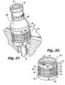
Fig. 21 is a perspective view of a portion of another exemplary embodiment of an injector constructed in accordance with the present invention, showing the machined spring mounted between the injector inlet and the feed arm; -
Fig. 22 is a perspective view of the machined spring ofFig. 21 , showing the axial wall sections between adjacent circumferential spring channels; -
Fig. 23 is a partial cross-sectional elevation view of the injector ofFig. 21 , showing the liquid conduit passing through the machined spring; and -
Fig. 24 is a cross-sectional elevation view of the injector ofFig. 23 , showing the circumferential spring channels. - Reference will now be made to the drawings wherein like reference numerals identify similar structural features or aspects of the subject invention. For purposes of explanation and illustration, and not limitation, a partial view of an exemplary embodiment of a machined spring in accordance with the invention is shown in
Fig. 1 and is designated generally byreference character 100. Other embodiments of machined springs in accordance with the invention, or aspects thereof, are provided inFigs. 2-24 , as will be described. The systems and methods of the invention can be used to improve spring performance, reduce part count, reduce part size, and to simplify assembly and manufacture, for example in fuel injectors for gas turbine engines. - Machined
spring 100 includes aspring portion 102 and aliquid strainer 104 integral withspring portion 102.Figs. 1 and 2 show thespring portion 102 and integralliquid strainer 104 from upstream and downstream perspectives, respectively.Fig. 3 showsspring portion 102 including opposed first and second spring bases 106 and 108 separated apart along a longitudinal axis A. Aspring body 110 connects the first and second spring bases 106 and 108. -
Spring body 110 includes a generally annular wall with twohelical spring channels Spring channels Spring channels spring channel 114 winds in a clockwise direction ascending around axis A as oriented inFig. 3 , andspring channel 112 winds in a counter-clockwise direction. Having separate spring channels wound in opposite directions advantageously provides uniform spring stiffness and reduces the tendency for buckling ofspring body 110 to one side under a substantially axial load when compared with helical springs having only one winding direction. - With reference now to
Fig. 4 ,spring base 108 includesliquid strainer 104.Liquid strainer 104 includes abulkhead 116 separating aflow passage 118 within the annular wall ofspring body 110 from aflow passage 120 withinliquid strainer 104. A plurality ofbores 122 are defined throughliquid strainer 104 for passage of liquid frompassage 118 inside the generally annular wall, throughbores 122, and aroundbulkhead 116 to the exterior of astrainer mesh 124 for straining liquid passing throughmesh 124 and strainer bores 125 intoflow passage 120 withinliquid strainer 104. This flow path is generally indicated by the heavy arrows inFig. 4 .Mesh 124 is not shown inFigs. 1-2 to avoid obscuring underlying strainer structure. The largely axial flow, with liquid moving from external ofstrainer mesh 124 into the axial flow path, is advantageous because external pressure on a strainer allows for high burst pressure compared to traditional strainer configurations. - Machined
spring 100 is compressed so thatliquid strainer 104 can be secured, e.g., bottomed, in aconduit 150 which can run between upstream and downstream ends of an injector, for example. The preload force provided byspring body 110, along with the three bearing guide surfaces 156 on the outer diameter of themachined spring 100, reduce the effect vibration loads may have on the device. Theinternal thread 152 aids in removal ofstrainer 104 for service or replacement. Outer o-ring 154 provides a seal to catch debris whenstrainer 104 is removed for service, and provides atrim orifice 158 for regulating flow. Having the spring and strainer integrated together reduces difficulties during assembly arising from a separate spring. - Referring now to
Figs. 5-6 , another exemplary embodiment of amachined spring 200 has aspring portion 202 andliquid strainer 204 much as described above but with a different flow path. Machinedspring 200 includes acircumferential land 217 extending outward from an upstream portion ofliquid strainer 204 with a plurality ofaxial channels 219 therethrough. As indicated by the heavy lines inFig. 8 , the flow path for straining liquid starts insidepassage 218, from which liquid flows out through thehelical spring channels axial channels 219 to the exterior of a strainer mesh 224 (which is only shown inFig. 8 ) where the liquid is strained by passing throughmesh 224 and strainer bores 225 intoflow passage 220 withinliquid strainer 204. Since the flow path includeshelical spring channels helical spring channels radial aperture 215, which are indicated inFig. 7 . Due to the relatively large size ofradial apertures 215 compared tospring channels spring channels radial apertures 215 permit uninterrupted liquid flow therethrough. - Referring now to
Figs. 9-11 , aprior art injector 300 is shown, in which two liquid flow circuits are provided.Fuel entering inlet 302 can pass throughpilot circuit 304 to be discharged frompilot nozzle 306, shown inFig. 11 . As pressure atinlet 302 increases, the pressure onplunger 308, shown inFig. 9 , provides increasing force to compressspring 310, which is shown inFig. 11 . Asplunger 308 moves farther intochamber 312, more and more ofscheduling feature 314, shown inFig. 10 , opens intomain circuit 312, allowing an increase of liquid flow throughmain circuit 312 to issue frommain nozzle 316. Due to the shape ofscheduling feature 314, the greater the pressure atinlet 302, the greater the flow will be passing throughmain circuit 312. Flow paths for the main andpilot circuits Fig. 11 . - With reference now to
Figs. 12-15 , an exemplary embodiment of aninjector 400 is shown, which utilizes amachined spring 401. The basic valve flow regulation ofinjector 400 is similar to that described above forinjector 300, including the uses ofinlet 402 shown inFig. 12 , main andpilot circuits Fig. 14 ,plunger 408 withscheduling feature 414 shown inFig. 13 , and main andpilot nozzles Fig. 14 . However, machinedspring 401 offers certain advantages overtraditional spring 310. Much as described above with respect to machinedspring 100, machinedspring 401 includes first and second spring bases 418 and 420 connected by aspring body 422 with two counter-windinghelical spring channels Fig. 15 . As pressure builds atinlet 402,helical spring channels scheduling feature 414 further intomain circuit 412. The spring constant and desired flow scheduling must be matched for each given application. Liquid frominlet 402 reaches both pilot andmain circuits spring body 422 out by way ofvalve cross-over 428, which is formed inspring base 420 as shown inFigs. 12-13 . Flow paths for the main andpilot circuits Fig. 14 .Plunger 408 withscheduling feature 414 form a scheduling valve member, andspring base 420 includes apeg 430 for mounting the scheduling valve member to machinedspring 401. Stop 436, identified inFig. 14 , provides a mechanical stop to prevent excessive inward travel ofplunger 408. The length ofinjector 400 can be shortened, including shorteningstop 436 without reducing the stroke length forplunger 408.Shortening injector 400 can advantageously reduce its weight and envelope size. - Three items, namely
valve retainer 332,spring seat 334, andspring 310, all shown inFig. 11 , can essentially be replaced by machinedspring 401. Due to the counter-winding ofhelical spring channels spring 310 is reduced or eliminated, increasing the wear life of the moving parts ininjector 400. In short, advantages of machinedspring 401 overtraditional spring 310 include reduced part count, reduced bearing surfaces for buckling issues, reduced need for hardened valve components (e.g., stainless steel valve components and heat treatment therefore, such as in typical 400SS valve components), and reduced valve envelope size and weight. - Referring now to
Figs. 16-20 , another advantageous use of machined springs in injectors is described.Figs. 16-17 show a prior art valve hold downcomponent 502 in aninjector 500. Hold downcomponent 502 is biased away frominjector wall 504 with atraditional wave spring 506 in compression therebetween withguide 528holding wave spring 506 in position. Hold downcomponent 502 in turn holdsvalve components 508 in proper position withinvalve seat 510. One disadvantage of this valve hold down configuration is that ifwave spring 506 looses its spring strength, valve hold downcomponent 502 can be rendered useless in holdingvalve components 508 in place. Often during assembly of injectors such asinjector 500, a welding process is performed to mountinjector wall 504 in place.Wave spring 506 is in the heat affected zone and can be annealed during the welding process.Annealing wave spring 506 reduces or eliminates its spring strength, rendering valve hold downcomponent 502 inoperative. -
Injector 600, shown inFigs. 18-20 , utilizes amachined spring 601 instead oftraditional wave spring 506.Injector 600 includesinjector wall 604,valve components 608 for regulating flow throughinjector 600, andvalve seat 610 much as described above with respect toinjector 500. Machinedspring 601 includes first and second spring bases 618 and 620 connected by aspring body 622 with two counter-windinghelical spring channels Fig. 20 , much as described above with respect to machinedspring 100.Spring base 618 includes a valve hold downcomponent 602 with anaxially extending guide 628. Wheninjector 600 is assembled, guide 628 is pressed againstinjector wall 604 as shown inFig. 19 , withhelical spring channels valve components 608 in place invalve seat 610.Guide 628 serves as a standoff tospace valve components 608 within the generally annular wall ofspring body 622 frominjector wall 604 and from the corresponding weld mountinginjector wall 604 in place. Sincespring body 622 is significantly spaced apart frominjector wall 604, weldinginjector wall 604 in place will have a significantly reduced chance of annealingspring body 622. In other words,spring body 622 is much more likely to be outside the heat affected zone when weldinginjector wall 604 in place compared toinjector 500, somachined spring 601 remains effective even after welding. Other advantages of machinedspring 601 include reduced part count, since the spring and hold down components are combined, and reduced guide diameter for improved heat resistance (compareguide 628 inFig. 18 to guide 528 inFig. 16 ). - With reference now to
Figs. 21-24 , anotherexemplary injector 700 and machinedspring 701 are explained. As shown inFig. 23 ,Injector 700 includesinlet 702 for receiving liquid, such as fuel, from an external source andoutlet 704 for injecting an atomized spray of the liquid, for example into the combustor of a gas turbine engine. Due to potentially high operating temperatures,feed arm 706 can heat up significantly during operation, whereas liquid flowing throughconduit 708 keeps theconduit 708 at a relatively cool temperature. Thus there is a potential for a significant thermal expansion gradient betweenfeed arm 706 andconduit 708 in operation. Machinedspring 701 is mounted at one end, e.g., spring base 710, to the inlet portion ofconduit 708 as shown inFig. 24 , with the fluid conveying portion ofconduit 708 running through the annular wall ofspring body 714 as shown inFig. 23 . The opposite end of machinedspring 701, e.g.,spring base 712, is mounted to feedarm 706 as shown inFig. 24 . Since machinedspring 701 is flexible along the longitudinal axis ofconduit 708, differences in thermal expansion betweenfeed arm 706 andconduit 708 can be accommodated by machinedspring 701, thereby avoiding harmful thermally induced stresses. - Referring now to
Figs. 21-22 , machinedspring 701 includes aspring body 714 defining an annular wall with a plurality ofspring channels 716 defined therethrough. Unlike the helical spring channels described above,spring channels 716 are circumferential, i.e., eachcircumferential spring channel 716 winds circumferentially around a portion of the annular wall to provide flexibility in the direction of the longitudinal axis B and stiffness in a torque direction around the longitudinal axis B circumferentially. Eachcircumferential spring channel 716 is paired with anotherspring channel 716 on a common circumference. Each such pair of channels has an axially extendingwall section 718 separating the twochannels 716 at each channel end. The axially extendingwall sections 718 of axially adjacent pairs ofchannels 716 are circumferentially offset from one another by about 90°. - This arrangement of circumferential channels and offset
wall sections 718 provides for flexibility along the axial direction, and also allows for stiffness in torsion so torque can be developed around the circumferential direction. This can be particularly advantageous if a torque must be applied toinlet 702 during installation, for example to attach a threaded fuel supply line toinlet 702. This configuration also gives good uniformity in the longitudinal flexibility of the annular wall ofspring body 714. Each spring channel end includes an optionalenlarged terminus 720 for reducing stress concentrations, as do the other embodiments of spring channels described above. Machinedspring 701 offers certain advantages over traditional measures, such as coiled conduits, used to accommodate differential thermal expansion of feed arms and liquid conduits therein. These advantages include simplified assembly, reduced weight, and use of a straight conduit rather than a more expensive coiled conduit. Optionally, a shield such as a telescoping tube, can be placed around the annular wall ofspring body 714 to keep debris from enteringchannels 716. - The methods and systems of the present invention, as described above and shown in the drawings, provide for machined springs and injectors with superior properties including enhanced spring and injector performance, reduced part count, and reduced size envelope. While the apparatus and methods of the subject invention have been shown and described with reference to preferred embodiments, those skilled in the art will readily appreciate that changes and/or modifications may be made thereto without departing from the scope of the subject invention.
Claims (15)
- A machined spring comprising:opposed first and second spring bases separated apart along a longitudinal axis; anda spring body connecting the first and second spring bases, wherein the spring body includes a generally annular wall with a first helical spring channel defined therethrough.
- A machined spring as recited in claim 1, wherein the generally annular wall further includes a second helical spring channel defined therethrough, wherein the first and second helical spring channels wind in counter-rotational directions around the annular wall for uniform spring stiffness and reduced buckling of the spring body to one side under a substantially axial load.
- A machined spring as recited in claim 1, wherein at least one of the spring bases includes a liquid strainer.
- A machined spring as recited in claim 3, wherein at least one of a) and b):-a) the liquid strainer includes a bulkhead separating a flow passage within the generally annular wall from a flow passage within the liquid strainer, wherein a plurality of bores are defined through the liquid strainer for passage of liquid from inside the generally annular wall through the bores and around the bulkhead to the exterior of a strainer mesh for straining liquid passing through the mesh into the flow passage within the liquid strainer;b) the liquid strainer includes a circumferential land extending outward from an upstream portion of the liquid strainer with a plurality of axial channels therethrough for passage of liquid out from inside the generally annular wall through the helical spring channels, through the axial channels to the exterior of a strainer mesh for straining liquid passing through the mesh into the flow passage within the liquid strainer.
- A machined spring as recited in claim 1, wherein the first helical spring channel includes a radial aperture configured to permit uninterrupted liquid flow therethrough even when the first helical spring channel is compressed axially.
- A machined spring as recited in claim 1, wherein at least one of a) and b):-a) at least one of the spring bases includes a valve cross-over configured and adapted to allow flow of liquid out from inside the generally annular wall through the valve cross-over for use in a valve;b) at least one of the spring bases includes a valve hold down component with an axially extending standoff configured to separate valve components within the generally annular wall from injector components outside the generally annular wall.
- A machined spring comprising:opposed first and second spring bases separated apart along a longitudinal axis; anda spring body connecting the first and second spring bases, wherein the spring body includes a generally annular wall with a plurality of circumferential spring channels defined therethrough, wherein each circumferential spring channel winds circumferentially around a portion of the annular wall to provide flexibility in the direction of the longitudinal axis and stiffness in a torque direction around the longitudinal axis circumferentially.
- A machined spring as recited in claim 7, wherein there are a plurality of pairs of the spring channels, each pair having an axially extending wall section separating the two channels at each channel end.
- A machined spring as recited in claim 8, wherein at least one of a) and b):-a) the axially extending wall sections between channel ends of each axially adjacent pair of channels are circumferentially offset from one another for increasing uniformity in longitudinal flexibility of the annular wall;b) the axially extending wall sections between channel ends of each axially adjacent pair of channels are circumferentially offset by about 90° from one another for increasing uniformity in longitudinal flexibility of the annular wall.
- A machined spring as recited in claim 7, wherein each channel end includes an enlarged terminus for reducing stress concentrations.
- A fuel injector comprising:an injector body having an upstream inlet end and opposed downstream end for injecting fluids therefrom;a machined spring mounted between the upstream inlet and downstream ends of the injector body, the machined spring including:opposed first and second spring bases separated apart along a longitudinal axis; anda spring body connecting the first and second spring bases, wherein the spring body includes a generally annular wall with a plurality of machined spring channels defined therethrough.
- A fuel injector as recited in claim 11, wherein the machined spring channels are helical and wind in counter-rotational directions around the annular wall to increase uniform spring stiffness and reduce buckling of the spring body to one side under a substantially axial load.
- A fuel injector as recited in claim 12, wherein at least one of the spring bases includes a liquid strainer for straining liquids flowing through the injector body, and
optionally:-
at least one of the machined spring channels includes a radial aperture configured to permit uninterrupted liquid flow therethrough even when the machined spring channels are compressed axially. - A fuel injector as recited in claim 11, further comprising a valve mounted in the injector body to regulate liquid flow therethrough, wherein at least one of a) and b):-a) at least one of the spring bases includes a valve cross-over mounted in the valve to allow flow of liquid out from inside the generally annular wall through the valve cross-over under a predetermined pressure range applied at the inlet end of the injector body.b) at least one of the spring bases includes a valve hold down component with an axially extending standoff separating the valve within the generally annular wall from injector components outside the generally annular wall.
- A fuel injector as recited in claim 11, wherein each machined spring channel is a circumferential spring channel that winds circumferentially around a portion of the annular wall to provide flexibility in the direction of the longitudinal axis and stiffness in a torque direction around the longitudinal axis circumferentially, wherein the first spring base is mounted to the inlet end of the injector body, wherein the second spring base is mounted to a feed arm of the injector, wherein a liquid conduit extends through the annular wall, and wherein the machined spring is configured and adapted to accommodate differential thermal expansion of the feed arm and liquid conduit and to provide stiffness to the inlet end of the injector body in torsion, and
optionally:-
wherein there are a plurality of pairs of the spring channels, each pair having an axially extending wall section separating the two channels at each channel end, and wherein the axially extending wall sections for each axially adjacent pair of channels are circumferentially offset.
Applications Claiming Priority (1)
| Application Number | Priority Date | Filing Date | Title |
|---|---|---|---|
| US13/302,477 US9068510B2 (en) | 2011-11-22 | 2011-11-22 | Machined springs for injector applications |
Publications (3)
| Publication Number | Publication Date |
|---|---|
| EP2597286A2 true EP2597286A2 (en) | 2013-05-29 |
| EP2597286A3 EP2597286A3 (en) | 2017-09-13 |
| EP2597286B1 EP2597286B1 (en) | 2020-03-04 |
Family
ID=47323884
Family Applications (1)
| Application Number | Title | Priority Date | Filing Date |
|---|---|---|---|
| EP12190664.8A Active EP2597286B1 (en) | 2011-11-22 | 2012-10-30 | Machined springs for injector applications |
Country Status (2)
| Country | Link |
|---|---|
| US (1) | US9068510B2 (en) |
| EP (1) | EP2597286B1 (en) |
Cited By (2)
| Publication number | Priority date | Publication date | Assignee | Title |
|---|---|---|---|---|
| CN106078801A (en) * | 2016-07-08 | 2016-11-09 | 北京空间飞行器总体设计部 | A kind of uiform section space manipulator armed lever telescoping mechanism |
| DE102018001566A1 (en) * | 2018-02-23 | 2019-09-26 | Woodward L'orange Gmbh | Dual-fuel fuel injector |
Families Citing this family (6)
| Publication number | Priority date | Publication date | Assignee | Title |
|---|---|---|---|---|
| US10161635B2 (en) * | 2014-06-13 | 2018-12-25 | Rolls-Royce Corporation | Combustor with spring-loaded crossover tubes |
| US9546600B2 (en) * | 2014-08-12 | 2017-01-17 | General Electric Company | Nozzle having an orifice plug for a gas turbomachine |
| US11131308B2 (en) * | 2016-06-06 | 2021-09-28 | National Oilwell Vareo, L.P. | Elastic and sealing elements in multi-stage pumps |
| US11053862B2 (en) * | 2017-09-25 | 2021-07-06 | Delavan Inc. | Electronic fuel control for gas turbine engines |
| US11786849B2 (en) * | 2019-11-27 | 2023-10-17 | Agco Corporation | Sprayer filtering system |
| TWI804324B (en) * | 2022-05-20 | 2023-06-01 | 黃建源 | Nozzle |
Family Cites Families (8)
| Publication number | Priority date | Publication date | Assignee | Title |
|---|---|---|---|---|
| JPH0794812B2 (en) * | 1987-12-29 | 1995-10-11 | トヨタ自動車株式会社 | Actuator for injector |
| US5062619A (en) * | 1989-04-03 | 1991-11-05 | Nabeya Kogyo Co., Ltd. | Non-linear spring |
| US7513372B2 (en) * | 2000-08-17 | 2009-04-07 | Carew E Bayne | Wave coil filter assembly |
| DE10213382A1 (en) * | 2002-03-26 | 2003-10-16 | Bosch Gmbh Robert | Fuel injection valve |
| US20090076614A1 (en) * | 2007-09-17 | 2009-03-19 | Spinalmotion, Inc. | Intervertebral Prosthetic Disc with Shock Absorption Core |
| DE102004028209A1 (en) * | 2004-06-09 | 2005-12-29 | Robert Bosch Gmbh | Fuel injection valve |
| US7950596B2 (en) * | 2008-06-27 | 2011-05-31 | Caterpillar Inc. | Distributed stiffness biasing spring for actuator system and fuel injector using same |
| US8378218B2 (en) * | 2009-11-13 | 2013-02-19 | Carleton Life Support Systems, Inc. | Spring with multiple conducting coils |
-
2011
- 2011-11-22 US US13/302,477 patent/US9068510B2/en active Active
-
2012
- 2012-10-30 EP EP12190664.8A patent/EP2597286B1/en active Active
Non-Patent Citations (1)
| Title |
|---|
| None |
Cited By (3)
| Publication number | Priority date | Publication date | Assignee | Title |
|---|---|---|---|---|
| CN106078801A (en) * | 2016-07-08 | 2016-11-09 | 北京空间飞行器总体设计部 | A kind of uiform section space manipulator armed lever telescoping mechanism |
| CN106078801B (en) * | 2016-07-08 | 2018-04-10 | 北京空间飞行器总体设计部 | A kind of uiform section space manipulator armed lever telescoping mechanism |
| DE102018001566A1 (en) * | 2018-02-23 | 2019-09-26 | Woodward L'orange Gmbh | Dual-fuel fuel injector |
Also Published As
| Publication number | Publication date |
|---|---|
| US20130126641A1 (en) | 2013-05-23 |
| EP2597286B1 (en) | 2020-03-04 |
| EP2597286A3 (en) | 2017-09-13 |
| US9068510B2 (en) | 2015-06-30 |
Similar Documents
| Publication | Publication Date | Title |
|---|---|---|
| US9068510B2 (en) | Machined springs for injector applications | |
| US20180058404A1 (en) | Fuel injector assembly with wire mesh damper | |
| US20090211256A1 (en) | Feed arm for a multiple circuit fuel injector | |
| US10584878B2 (en) | Flexible swirlers | |
| US8636263B2 (en) | System and method for locking retention of valve components | |
| JP2007309641A (en) | Device and method for compensating differential thermal expansion of injector component | |
| US9366191B2 (en) | Flexible shield for fluid connectors | |
| US8327649B2 (en) | Gas turbine fuel injector assembly with overlapping frictionally engaged members for damping vibrations | |
| US8511329B1 (en) | Metering valve | |
| CN109196203A (en) | Fuel delivery system for gas-turbine unit | |
| US9068511B2 (en) | Pressure regulating valve | |
| EP3182014A1 (en) | Injector fittings | |
| US9772054B2 (en) | Concentric flexible hose assembly | |
| US9958093B2 (en) | Flexible hose assembly with multiple flow passages | |
| CN114423928B (en) | Device for cooling the outer casing of a turbomachine and turbomachine provided with such a device | |
| US10041444B2 (en) | Variable orifice jet for a turbine engine | |
| US20150068620A1 (en) | Pressure regulating valve assembly | |
| US9151429B2 (en) | Flow restrictor | |
| CN114483365B (en) | Core machine test piece, connotation spray pipe and tail spray pipe of aeroengine | |
| US20180094816A1 (en) | Injector resonator for a gas turbine engine | |
| US20130199191A1 (en) | Fuel injector with increased feed area | |
| CN116006279A (en) | Interstage casing assembly, gas turbine engine and supporting method thereof |
Legal Events
| Date | Code | Title | Description |
|---|---|---|---|
| PUAI | Public reference made under article 153(3) epc to a published international application that has entered the european phase |
Free format text: ORIGINAL CODE: 0009012 |
|
| 17P | Request for examination filed |
Effective date: 20121030 |
|
| AK | Designated contracting states |
Kind code of ref document: A2 Designated state(s): AL AT BE BG CH CY CZ DE DK EE ES FI FR GB GR HR HU IE IS IT LI LT LU LV MC MK MT NL NO PL PT RO RS SE SI SK SM TR |
|
| AX | Request for extension of the european patent |
Extension state: BA ME |
|
| PUAL | Search report despatched |
Free format text: ORIGINAL CODE: 0009013 |
|
| AK | Designated contracting states |
Kind code of ref document: A3 Designated state(s): AL AT BE BG CH CY CZ DE DK EE ES FI FR GB GR HR HU IE IS IT LI LT LU LV MC MK MT NL NO PL PT RO RS SE SI SK SM TR |
|
| AX | Request for extension of the european patent |
Extension state: BA ME |
|
| RIC1 | Information provided on ipc code assigned before grant |
Ipc: F02C 7/232 20060101AFI20170804BHEP Ipc: F23K 5/18 20060101ALI20170804BHEP Ipc: F23K 5/14 20060101ALI20170804BHEP Ipc: F23R 3/28 20060101ALI20170804BHEP |
|
| STAA | Information on the status of an ep patent application or granted ep patent |
Free format text: STATUS: EXAMINATION IS IN PROGRESS |
|
| 17Q | First examination report despatched |
Effective date: 20180913 |
|
| GRAP | Despatch of communication of intention to grant a patent |
Free format text: ORIGINAL CODE: EPIDOSNIGR1 |
|
| STAA | Information on the status of an ep patent application or granted ep patent |
Free format text: STATUS: GRANT OF PATENT IS INTENDED |
|
| INTG | Intention to grant announced |
Effective date: 20190917 |
|
| GRAS | Grant fee paid |
Free format text: ORIGINAL CODE: EPIDOSNIGR3 |
|
| GRAA | (expected) grant |
Free format text: ORIGINAL CODE: 0009210 |
|
| STAA | Information on the status of an ep patent application or granted ep patent |
Free format text: STATUS: THE PATENT HAS BEEN GRANTED |
|
| AK | Designated contracting states |
Kind code of ref document: B1 Designated state(s): AL AT BE BG CH CY CZ DE DK EE ES FI FR GB GR HR HU IE IS IT LI LT LU LV MC MK MT NL NO PL PT RO RS SE SI SK SM TR |
|
| REG | Reference to a national code |
Ref country code: GB Ref legal event code: FG4D |
|
| REG | Reference to a national code |
Ref country code: CH Ref legal event code: EP |
|
| REG | Reference to a national code |
Ref country code: AT Ref legal event code: REF Ref document number: 1240632 Country of ref document: AT Kind code of ref document: T Effective date: 20200315 |
|
| REG | Reference to a national code |
Ref country code: DE Ref legal event code: R096 Ref document number: 602012068205 Country of ref document: DE |
|
| REG | Reference to a national code |
Ref country code: IE Ref legal event code: FG4D |
|
| PG25 | Lapsed in a contracting state [announced via postgrant information from national office to epo] |
Ref country code: RS Free format text: LAPSE BECAUSE OF FAILURE TO SUBMIT A TRANSLATION OF THE DESCRIPTION OR TO PAY THE FEE WITHIN THE PRESCRIBED TIME-LIMIT Effective date: 20200304 Ref country code: FI Free format text: LAPSE BECAUSE OF FAILURE TO SUBMIT A TRANSLATION OF THE DESCRIPTION OR TO PAY THE FEE WITHIN THE PRESCRIBED TIME-LIMIT Effective date: 20200304 Ref country code: NO Free format text: LAPSE BECAUSE OF FAILURE TO SUBMIT A TRANSLATION OF THE DESCRIPTION OR TO PAY THE FEE WITHIN THE PRESCRIBED TIME-LIMIT Effective date: 20200604 |
|
| REG | Reference to a national code |
Ref country code: NL Ref legal event code: MP Effective date: 20200304 |
|
| PG25 | Lapsed in a contracting state [announced via postgrant information from national office to epo] |
Ref country code: SE Free format text: LAPSE BECAUSE OF FAILURE TO SUBMIT A TRANSLATION OF THE DESCRIPTION OR TO PAY THE FEE WITHIN THE PRESCRIBED TIME-LIMIT Effective date: 20200304 Ref country code: LV Free format text: LAPSE BECAUSE OF FAILURE TO SUBMIT A TRANSLATION OF THE DESCRIPTION OR TO PAY THE FEE WITHIN THE PRESCRIBED TIME-LIMIT Effective date: 20200304 Ref country code: BG Free format text: LAPSE BECAUSE OF FAILURE TO SUBMIT A TRANSLATION OF THE DESCRIPTION OR TO PAY THE FEE WITHIN THE PRESCRIBED TIME-LIMIT Effective date: 20200604 Ref country code: HR Free format text: LAPSE BECAUSE OF FAILURE TO SUBMIT A TRANSLATION OF THE DESCRIPTION OR TO PAY THE FEE WITHIN THE PRESCRIBED TIME-LIMIT Effective date: 20200304 Ref country code: GR Free format text: LAPSE BECAUSE OF FAILURE TO SUBMIT A TRANSLATION OF THE DESCRIPTION OR TO PAY THE FEE WITHIN THE PRESCRIBED TIME-LIMIT Effective date: 20200605 |
|
| REG | Reference to a national code |
Ref country code: LT Ref legal event code: MG4D |
|
| PG25 | Lapsed in a contracting state [announced via postgrant information from national office to epo] |
Ref country code: NL Free format text: LAPSE BECAUSE OF FAILURE TO SUBMIT A TRANSLATION OF THE DESCRIPTION OR TO PAY THE FEE WITHIN THE PRESCRIBED TIME-LIMIT Effective date: 20200304 |
|
| PG25 | Lapsed in a contracting state [announced via postgrant information from national office to epo] |
Ref country code: SK Free format text: LAPSE BECAUSE OF FAILURE TO SUBMIT A TRANSLATION OF THE DESCRIPTION OR TO PAY THE FEE WITHIN THE PRESCRIBED TIME-LIMIT Effective date: 20200304 Ref country code: RO Free format text: LAPSE BECAUSE OF FAILURE TO SUBMIT A TRANSLATION OF THE DESCRIPTION OR TO PAY THE FEE WITHIN THE PRESCRIBED TIME-LIMIT Effective date: 20200304 Ref country code: IS Free format text: LAPSE BECAUSE OF FAILURE TO SUBMIT A TRANSLATION OF THE DESCRIPTION OR TO PAY THE FEE WITHIN THE PRESCRIBED TIME-LIMIT Effective date: 20200704 Ref country code: EE Free format text: LAPSE BECAUSE OF FAILURE TO SUBMIT A TRANSLATION OF THE DESCRIPTION OR TO PAY THE FEE WITHIN THE PRESCRIBED TIME-LIMIT Effective date: 20200304 Ref country code: SM Free format text: LAPSE BECAUSE OF FAILURE TO SUBMIT A TRANSLATION OF THE DESCRIPTION OR TO PAY THE FEE WITHIN THE PRESCRIBED TIME-LIMIT Effective date: 20200304 Ref country code: PT Free format text: LAPSE BECAUSE OF FAILURE TO SUBMIT A TRANSLATION OF THE DESCRIPTION OR TO PAY THE FEE WITHIN THE PRESCRIBED TIME-LIMIT Effective date: 20200729 Ref country code: LT Free format text: LAPSE BECAUSE OF FAILURE TO SUBMIT A TRANSLATION OF THE DESCRIPTION OR TO PAY THE FEE WITHIN THE PRESCRIBED TIME-LIMIT Effective date: 20200304 Ref country code: CZ Free format text: LAPSE BECAUSE OF FAILURE TO SUBMIT A TRANSLATION OF THE DESCRIPTION OR TO PAY THE FEE WITHIN THE PRESCRIBED TIME-LIMIT Effective date: 20200304 Ref country code: ES Free format text: LAPSE BECAUSE OF FAILURE TO SUBMIT A TRANSLATION OF THE DESCRIPTION OR TO PAY THE FEE WITHIN THE PRESCRIBED TIME-LIMIT Effective date: 20200304 |
|
| REG | Reference to a national code |
Ref country code: AT Ref legal event code: MK05 Ref document number: 1240632 Country of ref document: AT Kind code of ref document: T Effective date: 20200304 |
|
| REG | Reference to a national code |
Ref country code: DE Ref legal event code: R097 Ref document number: 602012068205 Country of ref document: DE |
|
| PLBE | No opposition filed within time limit |
Free format text: ORIGINAL CODE: 0009261 |
|
| STAA | Information on the status of an ep patent application or granted ep patent |
Free format text: STATUS: NO OPPOSITION FILED WITHIN TIME LIMIT |
|
| PG25 | Lapsed in a contracting state [announced via postgrant information from national office to epo] |
Ref country code: AT Free format text: LAPSE BECAUSE OF FAILURE TO SUBMIT A TRANSLATION OF THE DESCRIPTION OR TO PAY THE FEE WITHIN THE PRESCRIBED TIME-LIMIT Effective date: 20200304 Ref country code: DK Free format text: LAPSE BECAUSE OF FAILURE TO SUBMIT A TRANSLATION OF THE DESCRIPTION OR TO PAY THE FEE WITHIN THE PRESCRIBED TIME-LIMIT Effective date: 20200304 Ref country code: IT Free format text: LAPSE BECAUSE OF FAILURE TO SUBMIT A TRANSLATION OF THE DESCRIPTION OR TO PAY THE FEE WITHIN THE PRESCRIBED TIME-LIMIT Effective date: 20200304 |
|
| 26N | No opposition filed |
Effective date: 20201207 |
|
| PG25 | Lapsed in a contracting state [announced via postgrant information from national office to epo] |
Ref country code: SI Free format text: LAPSE BECAUSE OF FAILURE TO SUBMIT A TRANSLATION OF THE DESCRIPTION OR TO PAY THE FEE WITHIN THE PRESCRIBED TIME-LIMIT Effective date: 20200304 Ref country code: PL Free format text: LAPSE BECAUSE OF FAILURE TO SUBMIT A TRANSLATION OF THE DESCRIPTION OR TO PAY THE FEE WITHIN THE PRESCRIBED TIME-LIMIT Effective date: 20200304 |
|
| REG | Reference to a national code |
Ref country code: CH Ref legal event code: PL |
|
| PG25 | Lapsed in a contracting state [announced via postgrant information from national office to epo] |
Ref country code: LU Free format text: LAPSE BECAUSE OF NON-PAYMENT OF DUE FEES Effective date: 20201030 Ref country code: MC Free format text: LAPSE BECAUSE OF FAILURE TO SUBMIT A TRANSLATION OF THE DESCRIPTION OR TO PAY THE FEE WITHIN THE PRESCRIBED TIME-LIMIT Effective date: 20200304 |
|
| REG | Reference to a national code |
Ref country code: BE Ref legal event code: MM Effective date: 20201031 |
|
| PG25 | Lapsed in a contracting state [announced via postgrant information from national office to epo] |
Ref country code: LI Free format text: LAPSE BECAUSE OF NON-PAYMENT OF DUE FEES Effective date: 20201031 Ref country code: BE Free format text: LAPSE BECAUSE OF NON-PAYMENT OF DUE FEES Effective date: 20201031 Ref country code: CH Free format text: LAPSE BECAUSE OF NON-PAYMENT OF DUE FEES Effective date: 20201031 |
|
| PG25 | Lapsed in a contracting state [announced via postgrant information from national office to epo] |
Ref country code: IE Free format text: LAPSE BECAUSE OF NON-PAYMENT OF DUE FEES Effective date: 20201030 |
|
| PG25 | Lapsed in a contracting state [announced via postgrant information from national office to epo] |
Ref country code: TR Free format text: LAPSE BECAUSE OF FAILURE TO SUBMIT A TRANSLATION OF THE DESCRIPTION OR TO PAY THE FEE WITHIN THE PRESCRIBED TIME-LIMIT Effective date: 20200304 Ref country code: MT Free format text: LAPSE BECAUSE OF FAILURE TO SUBMIT A TRANSLATION OF THE DESCRIPTION OR TO PAY THE FEE WITHIN THE PRESCRIBED TIME-LIMIT Effective date: 20200304 Ref country code: CY Free format text: LAPSE BECAUSE OF FAILURE TO SUBMIT A TRANSLATION OF THE DESCRIPTION OR TO PAY THE FEE WITHIN THE PRESCRIBED TIME-LIMIT Effective date: 20200304 |
|
| PG25 | Lapsed in a contracting state [announced via postgrant information from national office to epo] |
Ref country code: MK Free format text: LAPSE BECAUSE OF FAILURE TO SUBMIT A TRANSLATION OF THE DESCRIPTION OR TO PAY THE FEE WITHIN THE PRESCRIBED TIME-LIMIT Effective date: 20200304 Ref country code: AL Free format text: LAPSE BECAUSE OF FAILURE TO SUBMIT A TRANSLATION OF THE DESCRIPTION OR TO PAY THE FEE WITHIN THE PRESCRIBED TIME-LIMIT Effective date: 20200304 |
|
| P01 | Opt-out of the competence of the unified patent court (upc) registered |
Effective date: 20230530 |
|
| PGFP | Annual fee paid to national office [announced via postgrant information from national office to epo] |
Ref country code: GB Payment date: 20230920 Year of fee payment: 12 |
|
| PGFP | Annual fee paid to national office [announced via postgrant information from national office to epo] |
Ref country code: FR Payment date: 20230920 Year of fee payment: 12 |
|
| PGFP | Annual fee paid to national office [announced via postgrant information from national office to epo] |
Ref country code: DE Payment date: 20230920 Year of fee payment: 12 |