EP4545745A1 - FRAMED SHIELDING WITH AT LEAST ONE MOTORIZED RAIL WITH INSTALLATION MECHANISMS - Google Patents
FRAMED SHIELDING WITH AT LEAST ONE MOTORIZED RAIL WITH INSTALLATION MECHANISMS Download PDFInfo
- Publication number
- EP4545745A1 EP4545745A1 EP24207771.7A EP24207771A EP4545745A1 EP 4545745 A1 EP4545745 A1 EP 4545745A1 EP 24207771 A EP24207771 A EP 24207771A EP 4545745 A1 EP4545745 A1 EP 4545745A1
- Authority
- EP
- European Patent Office
- Prior art keywords
- screen according
- rail
- screen
- motorized
- sliding element
- Prior art date
- Legal status (The legal status is an assumption and is not a legal conclusion. Google has not performed a legal analysis and makes no representation as to the accuracy of the status listed.)
- Pending
Links
Images





Classifications
-
- E—FIXED CONSTRUCTIONS
- E06—DOORS, WINDOWS, SHUTTERS, OR ROLLER BLINDS IN GENERAL; LADDERS
- E06B—FIXED OR MOVABLE CLOSURES FOR OPENINGS IN BUILDINGS, VEHICLES, FENCES OR LIKE ENCLOSURES IN GENERAL, e.g. DOORS, WINDOWS, BLINDS, GATES
- E06B9/00—Screening or protective devices for wall or similar openings, with or without operating or securing mechanisms; Closures of similar construction
- E06B9/24—Screens or other constructions affording protection against light, especially against sunshine; Similar screens for privacy or appearance; Slat blinds
- E06B9/26—Lamellar or like blinds, e.g. venetian blinds
- E06B9/28—Lamellar or like blinds, e.g. venetian blinds with horizontal lamellae, e.g. non-liftable
- E06B9/30—Lamellar or like blinds, e.g. venetian blinds with horizontal lamellae, e.g. non-liftable liftable
- E06B9/32—Operating, guiding, or securing devices therefor
- E06B9/322—Details of operating devices, e.g. pulleys, brakes, spring drums, drives
-
- E—FIXED CONSTRUCTIONS
- E06—DOORS, WINDOWS, SHUTTERS, OR ROLLER BLINDS IN GENERAL; LADDERS
- E06B—FIXED OR MOVABLE CLOSURES FOR OPENINGS IN BUILDINGS, VEHICLES, FENCES OR LIKE ENCLOSURES IN GENERAL, e.g. DOORS, WINDOWS, BLINDS, GATES
- E06B9/00—Screening or protective devices for wall or similar openings, with or without operating or securing mechanisms; Closures of similar construction
- E06B9/24—Screens or other constructions affording protection against light, especially against sunshine; Similar screens for privacy or appearance; Slat blinds
- E06B9/26—Lamellar or like blinds, e.g. venetian blinds
- E06B9/28—Lamellar or like blinds, e.g. venetian blinds with horizontal lamellae, e.g. non-liftable
- E06B9/30—Lamellar or like blinds, e.g. venetian blinds with horizontal lamellae, e.g. non-liftable liftable
- E06B9/32—Operating, guiding, or securing devices therefor
- E06B9/327—Guides for raisable lamellar blinds with horizontal lamellae
-
- E—FIXED CONSTRUCTIONS
- E06—DOORS, WINDOWS, SHUTTERS, OR ROLLER BLINDS IN GENERAL; LADDERS
- E06B—FIXED OR MOVABLE CLOSURES FOR OPENINGS IN BUILDINGS, VEHICLES, FENCES OR LIKE ENCLOSURES IN GENERAL, e.g. DOORS, WINDOWS, BLINDS, GATES
- E06B9/00—Screening or protective devices for wall or similar openings, with or without operating or securing mechanisms; Closures of similar construction
- E06B9/24—Screens or other constructions affording protection against light, especially against sunshine; Similar screens for privacy or appearance; Slat blinds
- E06B9/26—Lamellar or like blinds, e.g. venetian blinds
- E06B9/38—Other details
- E06B9/388—Details of bottom or upper slats or their attachment
-
- E—FIXED CONSTRUCTIONS
- E06—DOORS, WINDOWS, SHUTTERS, OR ROLLER BLINDS IN GENERAL; LADDERS
- E06B—FIXED OR MOVABLE CLOSURES FOR OPENINGS IN BUILDINGS, VEHICLES, FENCES OR LIKE ENCLOSURES IN GENERAL, e.g. DOORS, WINDOWS, BLINDS, GATES
- E06B9/00—Screening or protective devices for wall or similar openings, with or without operating or securing mechanisms; Closures of similar construction
- E06B9/24—Screens or other constructions affording protection against light, especially against sunshine; Similar screens for privacy or appearance; Slat blinds
- E06B9/26—Lamellar or like blinds, e.g. venetian blinds
- E06B9/262—Lamellar or like blinds, e.g. venetian blinds with flexibly-interconnected horizontal or vertical strips; Concertina blinds, i.e. upwardly folding flexible screens
- E06B2009/2625—Pleated screens, e.g. concertina- or accordion-like
-
- E—FIXED CONSTRUCTIONS
- E06—DOORS, WINDOWS, SHUTTERS, OR ROLLER BLINDS IN GENERAL; LADDERS
- E06B—FIXED OR MOVABLE CLOSURES FOR OPENINGS IN BUILDINGS, VEHICLES, FENCES OR LIKE ENCLOSURES IN GENERAL, e.g. DOORS, WINDOWS, BLINDS, GATES
- E06B9/00—Screening or protective devices for wall or similar openings, with or without operating or securing mechanisms; Closures of similar construction
- E06B9/24—Screens or other constructions affording protection against light, especially against sunshine; Similar screens for privacy or appearance; Slat blinds
- E06B9/26—Lamellar or like blinds, e.g. venetian blinds
- E06B9/28—Lamellar or like blinds, e.g. venetian blinds with horizontal lamellae, e.g. non-liftable
- E06B9/30—Lamellar or like blinds, e.g. venetian blinds with horizontal lamellae, e.g. non-liftable liftable
- E06B9/32—Operating, guiding, or securing devices therefor
- E06B9/322—Details of operating devices, e.g. pulleys, brakes, spring drums, drives
- E06B2009/3222—Cordless, i.e. user interface without cords
Definitions
- the present invention relates to a screen, such as a window covering comprising:
- a screen according to the preamble is known in the art and is suitable for use as a window covering for many types of windows, since it can be mounted in all sorts of positions: vertical, horizontal or diagonal.
- the invention has for its object to provide a screen according to the preamble that allows for easy installation by a user.
- this object is achieved by a screen according to the preamble, wherein in both outer ends of the motorized rail an installation mechanism is accommodated, which installation mechanism comprises movable suspension means on which the engaging means are attached and which is provided with operating means to put and lock the suspension means into an operating position, in which the engaging means engage the guide means.
- the screen according to the present invention can be shipped disassembled, while the users can do the installation themselves. During installation first the longitudinal profiles can be arranged in position and the motorized rail can be mounted later. After installation, the locking of the suspension means prevents a user from accidentally removing the engaging means out of the operating position.
- the installation mechanism comprises pushing means that force the suspension means in a free position, in which the engaging means are separate from the guide means.
- the pushing means ensure that, during mounting of the motorized rail in the longitudinal profiles, the engaging means remain at a distance from the guide means.
- the installation mechanism comprises a housing and the operating means comprise a sliding element, which protrudes out of the housing in an initial position and which is accommodated in the housing in an end position in which it locks the suspension means into the operating position.
- the sliding element In the initial position the sliding element can be easily accessed by the user after the motorized rail has been mounted in the frame. Once the sliding element is in the end position it is no longer accessible and consequently a one-time operation of the sliding element is ensured.
- the suspension means comprise a suspension arm that is pivotably arranged in the installation mechanism.
- the sliding element comprises an operating leg that puts and locks the suspension arm in the operating position in the end position of the sliding element.
- the pushing means comprise a pushing leg that is arranged on the sliding element and that forces the suspension arm into the free position in the initial position of the sliding element. Integrating the push means in the operating means allows for a compact design with fewer components that functions reliably at lower costs.
- the pushing means comprise spring means.
- the spring means comprise a torsion spring.
- the housing is embodied as an end cap for the motorized rail.
- the engaging means comprise pinion gears and the guide means comprise racks.
- the frame of the screen comprises one or two transverse profiles that connect the longitudinal profiles, e.g. to form a rectangular frame.
- the screen material is fixed to either one of the transverse profiles.
- the screen comprises a further rail that is to be mounted movably in the longitudinal profiles, wherein the screen material is carried by the two rails.
- the further rail can be a second motorized rail as well as a manually operable rail.
- the window covering is a pleated blind.
- the window covering is a roman blind.
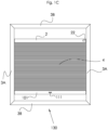
- FIGS 1A-1C show schematic front views of three variants of a first preferred embodiment of a screen according to the invention.
- the screen is a window covering, more specifically a Top-Down Bottom Up (TDBU) pleated blind.
- TDBU Top-Down Bottom Up
- the screen 100 comprises a frame 3 that is provided with two longitudinal profiles 3A that are to be arranged substantially parallel.
- the frame further comprises two transverse profiles 3B that connect the longitudinal profiles 3A to form a rectangular frame.
- a bottom rail 1 and a top rail 2 are mounted movably in the profiles 3A.
- At least one pleated screen material 4 is carried by the top rail 2 and the bottom rail 1.
- tensioning cords run through the pleated screen material 4 and tensioning devices (not shown) for tensioning the tensioning cords can be placed in the frame.
- the bottom rail 1 and the top rail 2 are both motorized.
- the motorized bottom rail 1 is provided with a control element 21.
- the motorized top rail 2 is provided with a control element 22.
- Guide means (shown in figures 3A and 3B ) run in the longitudinal profiles 3A and engaging means (also shown in figures 3A and 3B ) are provided at both ends of the motorized rail for engaging the guide means.
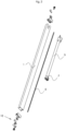
- FIG 2 the motorized bottom rail 1 of the screen of figures 1A and 1B is shown in exploded view. It is noted that the motorized top rail 2 comprises corresponding parts.
- a drive shaft 6 and a motor 5 for rotating the drive shaft 6 are accommodated.
- Engaging means 9 are provided on both ends of the drive shaft 6 for engaging the guide means 8.
- the motor 5 is provided with a position sensor (not shown).
- the position sensor is used to detect a collision. When a sudden reduction in speed is recognized, the motor is stopped.
- a suitable method therefor is implemented in suitable software for controlling the motor.
- An example of a suitable motor is an electrical motor.
- An example of a suitable position sensor is a position sensing encoder.
- the position sensing encoder comprises a rotary encoder connected to the drive shaft 6.
- an installation mechanism 10 is accommodated that is provided with movable suspension means on which the engaging means 9 are attached.
- the installation mechanism 10 is provided with operating means 15 to move the suspension means into an operating position, in which the engaging means 9 engage the guide means 8.
- Figure 3A schematically shows a detailed view of part of figure 1A from a different viewpoint.
- one end of the motorized top rail 2 is shown mounted in one of the longitudinal profiles 3A of the frame 3 with the engaging means 9 in a free position.
- part of the longitudinal profile 3A has been broken away.
- Figure 3B schematically shows the engaging means 9 of figure 3A in an operating position wherein they engage on the guide means 8.
- the engaging means comprise pinion gears 9 and the guide means comprise racks 8.
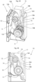
- Figure 4A schematically shows a detailed view of a first variant of the installation mechanism 10 of figure 3A .
- Figure 4B schematically shows a front view of the installation mechanism 10 of figure 3B .
- the installation mechanism 10 comprises a housing 11.
- the operating means comprise a sliding element 15 that protrudes out of the housing 11 in the initial position shown in figures 3A and 4A and that is substantially completely retracted and accommodated in the housing 11 in the end position shown in figures 3B and 4B .
- the housing 11 is embodied as an end cap for the motorized rail.
- the housing 11 fits in the profiles 3A.
- the movable suspension means comprise a suspension arm 13 that is pivotably arranged in the housing 11 on a shaft 12.
- the suspension arm 13 is provided with a rotating end 13A and with a supporting end 13B.
- the engaging means 9 are attached on the supporting end 13B of the suspension arm 13.
- the suspension arm 13 is pretensioned in the free position by a spring 14 that is arranged around the shaft 12 and abuts a first inner wall of the housing 11.
- a suitable spring is a torsion spring.
- the sliding element 15 preferably has a general wedge shape.
- the sliding element 15 has an operating leg 18 with a substantially oblique side 18A and a substantially straight side 18B that slides along a second inner wall of the housing 11.
- the sliding element 15 has a substantially oblique side 18A that corresponds to the shape of an adjacent side of the suspension arm 13.
- the sliding element 15 further has a cavity 15A corresponding in shape to the rotating end 13A.
- the sliding element 15 is provided with a longitudinal through opening 16 accommodating a longitudinal protrusion 17 present in the housing 11.
- the length of the opening 16 is longer than the length of the protrusion 17, so the sliding element 15 can slide from an initial position shown in figure 4A to an end position shown in figure 4B .
- an edge 16A is arranged to define a space in the opening with a shape corresponding to that of the protrusion 17.
- the protrusion 17 has passed the edge 16A and is locked in the opening 16 thereby locking the sliding element 15 in the end position.
- Figure 4C schematically shows a detailed view of a second variant of the installation mechanism in an initial position.
- Figure 4D schematically shows a detailed front view of the second variant of figure 4C in an end position.
- the installation mechanism 110 comprises a housing 111.
- the operating means comprise a sliding element 115 that protrudes out of the housing 111 in the initial position shown in figure 4C and that is substantially completely retracted and accommodated in the housing 111 in the end position shown in figure 4D .
- the housing 111 is embodied as an end cap for the motorized rail.
- the housing 111 fits in the profiles 3A.
- the movable suspension means comprise a suspension arm 113 that is pivotably arranged in the housing 111 on a shaft 112.
- the suspension arm 113 is provided with a rotating end 113A and with a supporting end 113B.
- the engaging means 9 are attached on the supporting end 113B of the suspension arm 113.
- the sliding element 115 preferably has a general U shape.
- the sliding element 115 has a cavity 115A corresponding in shape to the rotating end 113A.
- the sliding element 115 has two legs: an operating leg 118 and a pushing leg 119 that slide along opposite inner walls of the housing 111.
- the pushing leg 119 has a thickened end 119A with a pushing surface that corresponds at least partly to the shape of the rotating end 113A of suspension arm 113 arranged on the shaft 112.
- the pushing leg 119 rests against the adjacent first inner wall and forces the suspension arm 113 in the free position and blocks movement thereof.
- the pushing leg 119 is an alternative to the torsion spring 14 of the variant 10 of figures 4A and 4B .
- the operating leg 118 is provided with two grooves 116A and 116B that are spaced apart in longitudinal direction.
- the adjacent second inner wall of the housing 111 is provided with a ridge 117 that fits either one of the grooves 116A and 116B.
- a resilient member 114 is arranged that extends towards the adjacent second inner wall along which the operating leg 118 slides. In the initial position of the sliding element 115 shown in figure 4C the ridge 117 is accommodated in the lower groove 116B.
- the sliding element 115 can slide from the initial position shown in figure 4C to the end position shown in figure 4D .
- the pushing leg 119 seizes to block the suspension arm 113 and the operating leg 118 pushes the suspension arm 113 aside (to the left in figure 4D ) against the action of the resilient member 114 thus moving the engaging means 9 into the operating position.
- the operating leg 118 moves passed the resilient member 114 and the ridge 117 is locked in the upper groove 116A thereby locking the sliding element 115 in the end position.
- the rotating end 113A of the suspension arm 113 also rests in the correspondingly shaped cavity 115A of the sliding member 115.
- Figure 4E schematically shows a detailed view of a third variant of the installation mechanism in an initial position.
- Figure 4F schematically shows a detailed view of the third variant of figure 4E in an end position.
- Figure 4G schematically shows a cross section through plane GH of figure 4E .
- Figure 4H schematically shows a cross section through the plane GH of figure 4F .
- the installation mechanism 210 comprises a housing 211.
- the operating means comprise a sliding element 215 that protrudes out of the housing 211 in the initial position shown in figures 4E and 4G and that is substantially completely retracted and accommodated in the housing 211 in the end position shown in figures 4F and 4H .
- the housing 211 is embodied as an end cap for the motorized rail.
- the housing 211 fits in the profiles 3A.
- the movable suspension means comprise a suspension arm 213 that is pivotably arranged in the housing 211 on a shaft 212.
- the suspension arm 213 is provided with a rotating end 213A and with a supporting end 213B.
- the engaging means 9 are attached on the supporting end 213B of the suspension arm 13.
- suspension arm 213 is provided with a protrusion 213P on one side and a contact surface 213C on the opposite side, both located between the rotating end 213A and the supporting end 213B.
- the sliding element 215 has a cavity 215A corresponding in shape to the suspension arm rotating end 213A.
- the sliding element 215 has two legs: an operating leg 218 and a pushing leg 219 that slide along opposite inner walls of the housing 211.
- the pushing leg 219 has a bulging part 219A with a pushing surface that contacts the protrusion 213P in the initial position of the sliding element 215 shown in figure 4G . Consequently the pushing leg 219 forces the suspension arm 213 in the free position and blocks movement thereof.
- the pushing leg 219 is an alternative to the torsion spring 14 of the variant 10 of figures 4A and 4B .
- the operating leg 218 is provided with an operating and locking surface 218A arranged to cooperate with the contact surface 213C on the suspension arm.
- the sliding element 215 can slide from the initial position shown in figure 4G to the end position shown in figure 4H .
- the pushing leg 219 seizes to block the suspension arm 213 and the operating leg 218 pushes the suspension arm 213 aside (to the left) thus moving the engaging means 9 into the operating position.
- the operating leg 218 In the end position the operating leg 218 is positioned between the supporting end 213B of the suspension arm and the inner side of the housing 211.
- the operating and locking surface 218A is in contact with the contact surface 213C.
- the protrusion 213P is accommodated in a recess 219R present on the pushing leg 219.
- the rotating end 213A of the suspension arm 113 also rests in the correspondingly shaped cavity 215A of the sliding member 115.
- Figure 5A and 5B show schematic front views of two variants of a second preferred embodiment of a screen according to the invention.
- the screen is a window covering, more specifically a pleated blind with one motorized rail.
- the top rail 2 is motorized.
- the pleated material 4 is fixed to the lower transverse profile 3C.
- the bottom rail 1 is motorized.
- the pleated material 4 is fixed to the upper transverse profile 3C.
- FIG. 6 shows a schematic view of a third preferred embodiment of a screen according to the invention.
- the screen 300 is a window covering, more specifically a spring-operated roller blind with a motorized bottom rail 1.
- the frame 3 is provided with two longitudinal profiles 3A wherein the guide means run.
- the screen material is a roller blind 304 that is attached to a roller tube in the head rail 302.
- the roller tube preferably comprises a central rod and a tension spring.
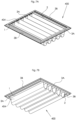
- Figures 7A and 7B show a schematic view of a fourth preferred embodiment of a screen according to the invention from different viewpoints.
- the screen 400 is a window covering, more specifically a roman blind with two motorized rails 1, 2.
- the screen material is a roman blind 404 that is attached on either side to the first motorized rail 1 and the second motorized rail 2.
- the screen 400 is suitable for a roof light and has a substantially horizontal orientation.
- the first motorized rail 1 respectively the second motorized rail 2 are now more accurately denoted as left motorized rail 1 respectively right motorized rail 2.
- the frame 3 is provided with two longitudinal profiles 3A wherein the guide means run and two transverse profiles 3B that connect the longitudinal profiles 3A to form a rectangular frame.
- the invention provides a framed screen with at least one motorized rail that has installation mechanisms with operating means at its outer ends.
- the drive shaft is movably suspended on its engaging means.
- the engaging means need to be moved and locked into an operating position by the operating means.
- each installation mechanism is designed to force the engaging means in a free position by bending the drive shaft at the outer ends.
- the outer ends of the drive shaft are bend out of alignment with the middle portion of the drive shaft that remains in line with the motorized rail in which it is accommodated. As a result the motorized rail can be easily mounted in the frame since the engaging means cannot engage the guide means.
- the sliding element incorporates an operating leg that acts, directly or indirectly, on the suspension arm.
- the sliding element further incorporates a pushing leg that acts on the suspension arm.
- locking means lock the sliding element in the housing.
- the installation mechanism comprises a pivotable suspension arm, but the invention extends to alternative embodiments wherein the installation mechanism comprising alternative movable suspension means.
- the installation mechanism comprising alternative movable suspension means.
- One non-limiting example is a suspension element that is shiftably arranged in the installation mechanism on which the engaging means are attached.
- any suitable guide means and engaging means can be used.
- Non limiting examples of other suitable guide means are tracks, belts, chains, rails, et cetera.
- Non limiting examples of other suitable engaging means are wheels, disks, rolls, et cetera.
- the invention is suitable for all types of screens with movable screen material, i.e. screen material that is retractable and collapsible between an inactive position, in which it is pleated, rolled up or folded to any active position in which it is less pleated, at least partly rolled out or unfolded.
- movable screen material i.e. screen material that is retractable and collapsible between an inactive position, in which it is pleated, rolled up or folded to any active position in which it is less pleated, at least partly rolled out or unfolded.
- the invention explicitly extends to other types of pleated blinds, such as pleated blinds having three rails mounted movably in the longitudinal profiles, wherein a middle rail is arranged movably between the top rail and the bottom rail.
- a first retractable screen material extends between the middle rail and the top rail
- a second retractable screen material extends between the middle rail and the bottom rail.
- the first and second retractable screen materials contain different types of fabric and said pleated blind is referred to as a Day/Night window covering.
- One, two or three of the rails can be a motorized according to the invention.
Landscapes
- Engineering & Computer Science (AREA)
- Structural Engineering (AREA)
- Architecture (AREA)
- Civil Engineering (AREA)
- Blinds (AREA)
Abstract
The invention relates to a screen (100), comprising a frame (3) provided with two longitudinal profiles (3A) that are to be arranged essentially in parallel, wherein guide means run in the longitudinal profiles, a retractable screen material (4) to be positioned in the frame, a motorized rail (1, 2) to which the screen material is attached and which is to be mounted movably in the longitudinal profiles, wherein in the motorized rail a drive shaft and a motor for rotating the drive shaft are accommodated, wherein engaging means are provided at both ends of the drive shaft for engaging the guide means. In both outer ends of the motorized rail an installation mechanism is accommodated, which comprises movable suspension means on which the engaging means are attached and which is provided with operating means to move and lock the suspension means into an operating position, in which the engaging means engage the guide means.
Description
- The present invention relates to a screen, such as a window covering comprising:
- a frame provided with two longitudinal profiles that are to be arranged essentially in parallel;
- guide means running in the longitudinal profiles;
- a retractable screen material to be positioned in the frame;
- a motorized rail to which the screen material is attached and which is to be mounted movably in the longitudinal profiles,
- wherein in the motorized rail a drive shaft and a motor for rotating the drive shaft are accommodated,
- wherein engaging means are provided at both ends of the drive shaft for engaging the guide means.
- A screen according to the preamble is known in the art and is suitable for use as a window covering for many types of windows, since it can be mounted in all sorts of positions: vertical, horizontal or diagonal.
- The invention has for its object to provide a screen according to the preamble that allows for easy installation by a user.
- According to the invention this object is achieved by a screen according to the preamble, wherein in both outer ends of the motorized rail an installation mechanism is accommodated, which installation mechanism comprises movable suspension means on which the engaging means are attached and which is provided with operating means to put and lock the suspension means into an operating position, in which the engaging means engage the guide means.
- The screen according to the present invention can be shipped disassembled, while the users can do the installation themselves. During installation first the longitudinal profiles can be arranged in position and the motorized rail can be mounted later. After installation, the locking of the suspension means prevents a user from accidentally removing the engaging means out of the operating position.
- According to a first preferred embodiment the installation mechanism comprises pushing means that force the suspension means in a free position, in which the engaging means are separate from the guide means. The pushing means ensure that, during mounting of the motorized rail in the longitudinal profiles, the engaging means remain at a distance from the guide means.
- According to a further preferred embodiment the installation mechanism comprises a housing and the operating means comprise a sliding element, which protrudes out of the housing in an initial position and which is accommodated in the housing in an end position in which it locks the suspension means into the operating position. In the initial position the sliding element can be easily accessed by the user after the motorized rail has been mounted in the frame. Once the sliding element is in the end position it is no longer accessible and consequently a one-time operation of the sliding element is ensured.
- In a practical preferred embodiment the suspension means comprise a suspension arm that is pivotably arranged in the installation mechanism.
- In an elegant combination of the preferred embodiments the sliding element comprises an operating leg that puts and locks the suspension arm in the operating position in the end position of the sliding element.
- According to a further combination of the preferred embodiments the pushing means comprise a pushing leg that is arranged on the sliding element and that forces the suspension arm into the free position in the initial position of the sliding element. Integrating the push means in the operating means allows for a compact design with fewer components that functions reliably at lower costs.
- In an alternative preferred embodiment the pushing means comprise spring means. Preferably the spring means comprise a torsion spring.
- In another practical elaboration of the further preferred embodiment the housing is embodied as an end cap for the motorized rail.
- Preferably the engaging means comprise pinion gears and the guide means comprise racks.
- In a versatile preferred embodiment the frame of the screen comprises one or two transverse profiles that connect the longitudinal profiles, e.g. to form a rectangular frame. In further variants thereof the screen material is fixed to either one of the transverse profiles. According to yet another variant the screen comprises a further rail that is to be mounted movably in the longitudinal profiles, wherein the screen material is carried by the two rails. The further rail can be a second motorized rail as well as a manually operable rail.
- According to a first and second preferred embodiment the window covering is a pleated blind.
- According to a third preferred embodiment the window covering is a roller blind.
- According to a fourth preferred embodiment the window covering is a roman blind.
- The invention will now be described in more detail with reference to the figures, in which:
-
Figure 1A shows a schematic front view of a first variant of a first preferred embodiment of a screen according to the invention; -
Figure 1B shows a schematic front view of a second variant of the first preferred embodiment of a screen according to the invention; -
Figure 1C shows a schematic front view of a third variant of the first preferred embodiment of a screen according to the invention; -
Figure 2 shows a motorized rail of the screens offigures 1A-1C in exploded view; -
Figure 3A schematically shows a detailed view of the top motorized rail of the screen offigure 1A with a first variant of an installation mechanism in an initial position; -
Figure 3B schematically shows the detailed view offigure 3A with said installation mechanism in an end position; -
Figure 4A schematically shows a detailed view of the installation mechanism offigure 3A ; -
Figure 4B schematically shows a detailed front view of the installation mechanism offigure 3B ; -
Figure 4C schematically shows a detailed view of a second variant of the installation mechanism in an initial position; -
Figure 4D schematically shows a detailed front view of the second variant offigure 4C in an end position; -
Figure 4E schematically shows a detailed view of a third variant of the installation mechanism in an initial position; -
Figure 4F schematically shows a detailed view of the third variant offigure 4E in an end position; -
Figure 4G schematically shows a cross section of the third variant in the initial position; -
Figure 4H schematically shows a cross section of the third variant in the end position; -
Figure 5A shows a schematic view of a first variant of a second preferred embodiment of a screen according to the invention; -
Figure 5B shows a schematic view of a second variant of a second preferred embodiment of a screen according to the invention; -
Figure 6 shows a schematic view of a third preferred embodiment of a screen according to the invention; -
Figure 7A shows a schematic top view of a fourth preferred embodiment of a screen according to the invention; and -
Figure 7B shows a schematic bottom view of the fourth preferred offigure 7B . - The same components are designated in the different figures with the same reference numerals.
-
Figures 1A-1C show schematic front views of three variants of a first preferred embodiment of a screen according to the invention. Herein the screen is a window covering, more specifically a Top-Down Bottom Up (TDBU) pleated blind. - In
figure 1A thescreen 100 comprises aframe 3 that is provided with twolongitudinal profiles 3A that are to be arranged substantially parallel. The frame further comprises twotransverse profiles 3B that connect thelongitudinal profiles 3A to form a rectangular frame. - A
bottom rail 1 and atop rail 2 are mounted movably in theprofiles 3A. At least one pleatedscreen material 4 is carried by thetop rail 2 and thebottom rail 1. As is known in the art of tensioned pleated blinds tensioning cords run through the pleatedscreen material 4 and tensioning devices (not shown) for tensioning the tensioning cords can be placed in the frame. - In the first variant of
figure 1A thebottom rail 1 and thetop rail 2 are both motorized. Preferably the motorizedbottom rail 1 is provided with acontrol element 21. Preferably the motorizedtop rail 2 is provided with acontrol element 22. Guide means (shown infigures 3A and 3B ) run in thelongitudinal profiles 3A and engaging means (also shown infigures 3A and 3B ) are provided at both ends of the motorized rail for engaging the guide means. - In the second variant shown in
figure 1B in thescreen 120 only thebottom rail 1 is motorized while thetop rail 102 is manually operable. Thereto on the top rail 102 ahandle 121 is provided. - In the third variant shown in
figure 1C in thescreen 130 only thetop rail 2 is motorized while thebottom rail 101 is manually operable. Thereto on the bottom rail 101 ahandle 111 is provided. - In
figure 2 themotorized bottom rail 1 of the screen offigures 1A and1B is shown in exploded view. It is noted that the motorizedtop rail 2 comprises corresponding parts. - In the motorized bottom rail 1 a
drive shaft 6 and amotor 5 for rotating thedrive shaft 6 are accommodated. Engaging means 9 are provided on both ends of thedrive shaft 6 for engaging the guide means 8. - The
motor 5 is provided with a position sensor (not shown). The position sensor is used to detect a collision. When a sudden reduction in speed is recognized, the motor is stopped. A suitable method therefor is implemented in suitable software for controlling the motor. - An example of a suitable motor is an electrical motor. An example of a suitable position sensor is a position sensing encoder. In a preferred embodiment the position sensing encoder comprises a rotary encoder connected to the
drive shaft 6. - In both outer ends of the
motorized bottom rail 1 aninstallation mechanism 10 is accommodated that is provided with movable suspension means on which the engagingmeans 9 are attached. Theinstallation mechanism 10 is provided with operating means 15 to move the suspension means into an operating position, in which the engagingmeans 9 engage the guide means 8. -
Figure 3A schematically shows a detailed view of part offigure 1A from a different viewpoint. Herein one end of the motorizedtop rail 2 is shown mounted in one of thelongitudinal profiles 3A of theframe 3 with the engagingmeans 9 in a free position. For clarity part of thelongitudinal profile 3A has been broken away. -
Figure 3B schematically shows the engagingmeans 9 offigure 3A in an operating position wherein they engage on the guide means 8. In the preferred embodiments shown the engaging means comprise pinion gears 9 and the guide means comprise racks 8. -
Figure 4A schematically shows a detailed view of a first variant of theinstallation mechanism 10 offigure 3A . -
Figure 4B schematically shows a front view of theinstallation mechanism 10 offigure 3B . - The
installation mechanism 10 comprises ahousing 11. The operating means comprise a slidingelement 15 that protrudes out of thehousing 11 in the initial position shown infigures 3A and4A and that is substantially completely retracted and accommodated in thehousing 11 in the end position shown infigures 3B and4B . - The
housing 11 is embodied as an end cap for the motorized rail. Thehousing 11 fits in theprofiles 3A. - In the preferred embodiment shown the movable suspension means comprise a
suspension arm 13 that is pivotably arranged in thehousing 11 on ashaft 12. Thesuspension arm 13 is provided with arotating end 13A and with a supportingend 13B. The engaging means 9 are attached on the supportingend 13B of thesuspension arm 13. - The
suspension arm 13 is pretensioned in the free position by aspring 14 that is arranged around theshaft 12 and abuts a first inner wall of thehousing 11. A suitable spring is a torsion spring. - In the first variant the sliding
element 15 preferably has a general wedge shape. The slidingelement 15 has an operatingleg 18 with a substantiallyoblique side 18A and a substantiallystraight side 18B that slides along a second inner wall of thehousing 11. In the preferred embodiment shown the slidingelement 15 has a substantiallyoblique side 18A that corresponds to the shape of an adjacent side of thesuspension arm 13. The slidingelement 15 further has acavity 15A corresponding in shape to therotating end 13A. - The sliding
element 15 is provided with a longitudinal through opening 16 accommodating alongitudinal protrusion 17 present in thehousing 11. The length of theopening 16 is longer than the length of theprotrusion 17, so the slidingelement 15 can slide from an initial position shown infigure 4A to an end position shown infigure 4B . In the upper part of the opening 16 anedge 16A is arranged to define a space in the opening with a shape corresponding to that of theprotrusion 17. In the end position theprotrusion 17 has passed theedge 16A and is locked in theopening 16 thereby locking the slidingelement 15 in the end position. During sliding from the initial position to the end position the slidingelement 15 pushes thesuspension arm 13 aside (to the left infigure 4A ) against the action of thespring 14 thus putting the engagingmeans 9 into the operating position. In the end position thesuspension arm 13 rests against the correspondingly shaped adjacentoblique side 18A. Therotating end 13A rests in thecavity 15A. -
Figure 4C schematically shows a detailed view of a second variant of the installation mechanism in an initial position.Figure 4D schematically shows a detailed front view of the second variant offigure 4C in an end position. - The
installation mechanism 110 comprises ahousing 111. The operating means comprise a slidingelement 115 that protrudes out of thehousing 111 in the initial position shown infigure 4C and that is substantially completely retracted and accommodated in thehousing 111 in the end position shown infigure 4D . - The
housing 111 is embodied as an end cap for the motorized rail. Thehousing 111 fits in theprofiles 3A. - In the preferred embodiment shown the movable suspension means comprise a
suspension arm 113 that is pivotably arranged in thehousing 111 on ashaft 112. Thesuspension arm 113 is provided with arotating end 113A and with a supportingend 113B. The engaging means 9 are attached on the supportingend 113B of thesuspension arm 113. - In the second variant the sliding
element 115 preferably has a general U shape. The slidingelement 115 has acavity 115A corresponding in shape to therotating end 113A. The slidingelement 115 has two legs: an operatingleg 118 and a pushingleg 119 that slide along opposite inner walls of thehousing 111. In the variant shown the pushingleg 119 has a thickenedend 119A with a pushing surface that corresponds at least partly to the shape of therotating end 113A ofsuspension arm 113 arranged on theshaft 112. In the initial position of the slidingelement 115 shown infigure 4C the pushingleg 119 rests against the adjacent first inner wall and forces thesuspension arm 113 in the free position and blocks movement thereof. The pushingleg 119 is an alternative to thetorsion spring 14 of thevariant 10 offigures 4A and 4B . - The
operating leg 118 is provided with twogrooves housing 111 is provided with aridge 117 that fits either one of thegrooves resilient member 114 is arranged that extends towards the adjacent second inner wall along which theoperating leg 118 slides. In the initial position of the slidingelement 115 shown infigure 4C theridge 117 is accommodated in thelower groove 116B. - The sliding
element 115 can slide from the initial position shown infigure 4C to the end position shown infigure 4D . During sliding from the initial position to the end position the pushingleg 119 seizes to block thesuspension arm 113 and theoperating leg 118 pushes thesuspension arm 113 aside (to the left infigure 4D ) against the action of theresilient member 114 thus moving the engagingmeans 9 into the operating position. In the end position theoperating leg 118 moves passed theresilient member 114 and theridge 117 is locked in theupper groove 116A thereby locking the slidingelement 115 in the end position. In the end position therotating end 113A of thesuspension arm 113 also rests in the correspondingly shapedcavity 115A of the slidingmember 115. -
Figure 4E schematically shows a detailed view of a third variant of the installation mechanism in an initial position.Figure 4F schematically shows a detailed view of the third variant offigure 4E in an end position.Figure 4G schematically shows a cross section through plane GH offigure 4E .Figure 4H schematically shows a cross section through the plane GH offigure 4F . Theinstallation mechanism 210 comprises ahousing 211. The operating means comprise a slidingelement 215 that protrudes out of thehousing 211 in the initial position shown infigures 4E and4G and that is substantially completely retracted and accommodated in thehousing 211 in the end position shown infigures 4F and4H . - The
housing 211 is embodied as an end cap for the motorized rail. Thehousing 211 fits in theprofiles 3A. - The movable suspension means comprise a
suspension arm 213 that is pivotably arranged in thehousing 211 on ashaft 212. Thesuspension arm 213 is provided with arotating end 213A and with a supportingend 213B. The engaging means 9 are attached on the supportingend 213B of thesuspension arm 13. - In the third variant the sliding
element 215 is provided with a longitudinal throughopening 216 accommodating theshaft 212. Theopening 216 is slotted, so the slidingelement 215 can slide from the initial position shown infigure 4E to the end position shown infigure 4F . In the upper part of theopening 216 two oppositeupper edges 216A are arranged to define an upper space in the opening with a shape corresponding to that of theshaft 212. In the lower part of theopening 216 two opposite edges lower 216B are arranged to define a lower space in the opening with a shape corresponding to that of theshaft 212. - In the initial position of
figure 4E theshaft 212 is situated under thelower edges 216B and is locked in the lower space of opening 216 thereby locking the slidingelement 215 in the initial position. In the end position offigure 4F theupper edges 216A have passed theshaft 212 that is now locked in the upper space of theopening 216 thereby locking the slidingelement 215 in the end position. - In the third variant the
suspension arm 213 is provided with aprotrusion 213P on one side and acontact surface 213C on the opposite side, both located between therotating end 213A and the supportingend 213B. - The sliding
element 215 has acavity 215A corresponding in shape to the suspensionarm rotating end 213A. In the third variant shown the slidingelement 215 has two legs: an operatingleg 218 and a pushingleg 219 that slide along opposite inner walls of thehousing 211. In the variant shown the pushingleg 219 has abulging part 219A with a pushing surface that contacts theprotrusion 213P in the initial position of the slidingelement 215 shown infigure 4G . Consequently the pushingleg 219 forces thesuspension arm 213 in the free position and blocks movement thereof. The pushingleg 219 is an alternative to thetorsion spring 14 of thevariant 10 offigures 4A and 4B . - The
operating leg 218 is provided with an operating and lockingsurface 218A arranged to cooperate with thecontact surface 213C on the suspension arm. - The sliding
element 215 can slide from the initial position shown infigure 4G to the end position shown infigure 4H . During sliding from the initial position to the end position the pushingleg 219 seizes to block thesuspension arm 213 and theoperating leg 218 pushes thesuspension arm 213 aside (to the left) thus moving the engagingmeans 9 into the operating position. In the end position theoperating leg 218 is positioned between the supportingend 213B of the suspension arm and the inner side of thehousing 211. The operating and lockingsurface 218A is in contact with thecontact surface 213C. Theprotrusion 213P is accommodated in arecess 219R present on the pushingleg 219. In the end position therotating end 213A of thesuspension arm 113 also rests in the correspondingly shapedcavity 215A of the slidingmember 115. -
Figure 5A and5B show schematic front views of two variants of a second preferred embodiment of a screen according to the invention. Herein the screen is a window covering, more specifically a pleated blind with one motorized rail. In the variant shown infigure 5A thetop rail 2 is motorized. Thepleated material 4 is fixed to the lowertransverse profile 3C. In the variant shown infigure 5B thebottom rail 1 is motorized. Thepleated material 4 is fixed to the uppertransverse profile 3C. -
Figure 6 shows a schematic view of a third preferred embodiment of a screen according to the invention. In the third preferred embodiment thescreen 300 is a window covering, more specifically a spring-operated roller blind with amotorized bottom rail 1. Theframe 3 is provided with twolongitudinal profiles 3A wherein the guide means run. The screen material is aroller blind 304 that is attached to a roller tube in thehead rail 302. The roller tube preferably comprises a central rod and a tension spring. -
Figures 7A and 7B show a schematic view of a fourth preferred embodiment of a screen according to the invention from different viewpoints. In the fourth preferred embodiment thescreen 400 is a window covering, more specifically a roman blind with twomotorized rails motorized rail 1 and the secondmotorized rail 2. Thescreen 400 is suitable for a roof light and has a substantially horizontal orientation. The firstmotorized rail 1 respectively the secondmotorized rail 2 are now more accurately denoted as leftmotorized rail 1 respectively rightmotorized rail 2. Theframe 3 is provided with twolongitudinal profiles 3A wherein the guide means run and twotransverse profiles 3B that connect thelongitudinal profiles 3A to form a rectangular frame. - The invention provides a framed screen with at least one motorized rail that has installation mechanisms with operating means at its outer ends. In the installation mechanisms the drive shaft is movably suspended on its engaging means. After installation of the motorized rail in the frame, the engaging means need to be moved and locked into an operating position by the operating means. Preferably each installation mechanism is designed to force the engaging means in a free position by bending the drive shaft at the outer ends. The outer ends of the drive shaft are bend out of alignment with the middle portion of the drive shaft that remains in line with the motorized rail in which it is accommodated. As a result the motorized rail can be easily mounted in the frame since the engaging means cannot engage the guide means.
- Three different variants of the installation mechanism are shown and described. In all variants the sliding element incorporates an operating leg that acts, directly or indirectly, on the suspension arm. In the second and third variant the sliding element further incorporates a pushing leg that acts on the suspension arm. In all variants locking means lock the sliding element in the housing.
- The invention is of course not limited to the described and shown preferred embodiments.
- As an example in the preferred embodiments shown the installation mechanism comprises a pivotable suspension arm, but the invention extends to alternative embodiments wherein the installation mechanism comprising alternative movable suspension means. One non-limiting example is a suspension element that is shiftably arranged in the installation mechanism on which the engaging means are attached.
- It is furthermore noted that any suitable guide means and engaging means can be used. Non limiting examples of other suitable guide means are tracks, belts, chains, rails, et cetera. Non limiting examples of other suitable engaging means are wheels, disks, rolls, et cetera.
- The invention is suitable for all types of screens with movable screen material, i.e. screen material that is retractable and collapsible between an inactive position, in which it is pleated, rolled up or folded to any active position in which it is less pleated, at least partly rolled out or unfolded.
- The invention explicitly extends to other types of pleated blinds, such as pleated blinds having three rails mounted movably in the longitudinal profiles, wherein a middle rail is arranged movably between the top rail and the bottom rail. Herein a first retractable screen material extends between the middle rail and the top rail and a second retractable screen material extends between the middle rail and the bottom rail. In the art in such a pleated blind usually the first and second retractable screen materials contain different types of fabric and said pleated blind is referred to as a Day/Night window covering. One, two or three of the rails can be a motorized according to the invention.
- Consequently the invention extends to any embodiment falling within the scope of protection as defined in the claims and as seen in the light of the foregoing description and accompanying drawings.
Claims (15)
- Screen, such as a window covering, comprising:a frame provided with two longitudinal profiles that are to be arranged essentially in parallel;guide means running in the longitudinal profiles;a retractable screen material to be positioned in the frame;a motorized rail to which the screen material is attached and which is to be mounted movably in the longitudinal profiles,wherein in the motorized rail a drive shaft and a motor for rotating the drive shaft are accommodated,wherein engaging means are provided at both ends of the drive shaft for engaging the guide means, characterized in thatin both outer ends of the motorized rail an installation mechanism is accommodated, which installation mechanism comprises movable suspension means on which the engaging means are attached and which installation mechanism is provided with operating means to put and lock the suspension means into an operating position, in which the engaging means engage the guide means.
- Screen according to claim 1, wherein the installation mechanism comprises pushing means that force the suspension means in a free position, in which the engaging means are separate from the guide means when the motorized rail is mounted in the longitudinal profiles.
- Screen according any one of the preceding claims, wherein the installation mechanism comprises a housing and wherein the operating means comprise a sliding element, which protrudes out of the housing in an initial position and which is accommodated in the housing in an end position in which it locks the suspension means into the operating position.
- Screen according any one of the preceding claims, wherein the suspension means comprise a suspension arm that is pivotably arranged in the installation mechanism.
- Screen according to claim 4 referring to claim 3, wherein the sliding element comprises an operating leg that puts and locks the suspension arm in the operating position in the end position of the sliding element.
- Screen according to claim 4 referring to claim 3 and 2, wherein the pushing means comprise a pushing leg that is arranged on the sliding element and that forces the suspension arm into the free position in the initial position of the sliding element.
- Screen according any one of the preceding claims 2-5, , wherein the pushing means comprise spring means, preferably a torsion spring.
- Screen according any one of the preceding claims 3-7, wherein the housing is embodied as an end cap for the motorized rail.
- Screen according any one of the preceding claims, wherein the engaging means comprise pinion gears and the guide means comprise racks.
- Screen according any one of the preceding claims, wherein the frame comprises one or two transverse profiles that connect the longitudinal profiles.
- Screen according to claim 10, wherein the screen material is fixed to one of the transverse profiles.
- Screen according any one of the preceding claims, comprising a further rail that is to be mounted movably in the longitudinal profiles, wherein the screen material is carried by the two rails.
- Screen according to claim 12, wherein the further rail is a second motorized rail.
- Screen according to claim 12, wherein the further rail is manually operable.
- Screen according any one of the preceding claims, wherein the window covering is a pleated blind, a roller blind or a roman blind.
Applications Claiming Priority (2)
| Application Number | Priority Date | Filing Date | Title |
|---|---|---|---|
| NL2036132 | 2023-10-26 | ||
| NL2036210A NL2036210B1 (en) | 2023-10-26 | 2023-11-08 | Framed screen with at least one motorized rail with installation mechanisms |
Publications (1)
| Publication Number | Publication Date |
|---|---|
| EP4545745A1 true EP4545745A1 (en) | 2025-04-30 |
Family
ID=93214925
Family Applications (1)
| Application Number | Title | Priority Date | Filing Date |
|---|---|---|---|
| EP24207771.7A Pending EP4545745A1 (en) | 2023-10-26 | 2024-10-21 | FRAMED SHIELDING WITH AT LEAST ONE MOTORIZED RAIL WITH INSTALLATION MECHANISMS |
Country Status (2)
| Country | Link |
|---|---|
| EP (1) | EP4545745A1 (en) |
| AU (1) | AU2024227564A1 (en) |
Citations (2)
| Publication number | Priority date | Publication date | Assignee | Title |
|---|---|---|---|---|
| EP2738342A1 (en) * | 2012-12-03 | 2014-06-04 | VKR Holding A/S | A screening arrangement for a window |
| US9115766B2 (en) * | 2013-08-09 | 2015-08-25 | Nien Made Enterprise Co., Ltd. | Coupling module of window covering |
-
2024
- 2024-10-21 EP EP24207771.7A patent/EP4545745A1/en active Pending
- 2024-10-23 AU AU2024227564A patent/AU2024227564A1/en active Pending
Patent Citations (2)
| Publication number | Priority date | Publication date | Assignee | Title |
|---|---|---|---|---|
| EP2738342A1 (en) * | 2012-12-03 | 2014-06-04 | VKR Holding A/S | A screening arrangement for a window |
| US9115766B2 (en) * | 2013-08-09 | 2015-08-25 | Nien Made Enterprise Co., Ltd. | Coupling module of window covering |
Also Published As
| Publication number | Publication date |
|---|---|
| AU2024227564A1 (en) | 2025-05-22 |
Similar Documents
| Publication | Publication Date | Title |
|---|---|---|
| CN1108434C (en) | Guides for soft rolling doors and soft rolling doors | |
| US9347261B2 (en) | Adjustment mechanisms for shades | |
| US8662137B2 (en) | Attachment of an architectural covering | |
| US5033527A (en) | Motorized roller blind | |
| CA1177745A (en) | Roller blind | |
| EP3000958B1 (en) | Fabric roller blind | |
| US20170362887A1 (en) | Slat control mechanism for blinds | |
| NL2036210B1 (en) | Framed screen with at least one motorized rail with installation mechanisms | |
| AU2024227564A1 (en) | Framed screen with at least one motorized rail with installation mechanisms | |
| MXPA03002731A (en) | Blind assembly having fabric blind slats. | |
| US6035920A (en) | Screening arrangement | |
| EP1022428B1 (en) | A window screening arrangement and a braking device for use therein | |
| SK285952B6 (en) | A roller shutter | |
| JP4862439B2 (en) | Blind device | |
| EP1577458A1 (en) | Vertical awning comprising an automatic device for the taut fixing thereof in the partially or totally extended position | |
| GB2162226A (en) | Venetian blind | |
| CH649603A5 (en) | SHUTTER. | |
| CN223420466U (en) | Manual side window roller blind device | |
| JPH0328712Y2 (en) | ||
| RU2054115C1 (en) | Lightproof device | |
| EP3636872B1 (en) | Fabric roller blind | |
| AU2006200242B2 (en) | Retractable Screen | |
| JP2002168068A (en) | Blind apparatus | |
| EP4660411A1 (en) | Telescopic handling system for lateral sliding shields | |
| KR200340806Y1 (en) | Shutter assembly |
Legal Events
| Date | Code | Title | Description |
|---|---|---|---|
| PUAI | Public reference made under article 153(3) epc to a published international application that has entered the european phase |
Free format text: ORIGINAL CODE: 0009012 |
|
| STAA | Information on the status of an ep patent application or granted ep patent |
Free format text: STATUS: THE APPLICATION HAS BEEN PUBLISHED |
|
| AK | Designated contracting states |
Kind code of ref document: A1 Designated state(s): AL AT BE BG CH CY CZ DE DK EE ES FI FR GB GR HR HU IE IS IT LI LT LU LV MC ME MK MT NL NO PL PT RO RS SE SI SK SM TR |
|
| STAA | Information on the status of an ep patent application or granted ep patent |
Free format text: STATUS: REQUEST FOR EXAMINATION WAS MADE |
|
| 17P | Request for examination filed |
Effective date: 20250929 |