EP3000958B1 - Fabric roller blind - Google Patents
Fabric roller blind Download PDFInfo
- Publication number
- EP3000958B1 EP3000958B1 EP15186702.5A EP15186702A EP3000958B1 EP 3000958 B1 EP3000958 B1 EP 3000958B1 EP 15186702 A EP15186702 A EP 15186702A EP 3000958 B1 EP3000958 B1 EP 3000958B1
- Authority
- EP
- European Patent Office
- Prior art keywords
- bottom bar
- lateral
- blind
- guiding
- fabric
- Prior art date
- Legal status (The legal status is an assumption and is not a legal conclusion. Google has not performed a legal analysis and makes no representation as to the accuracy of the status listed.)
- Active
Links
- 239000004744 fabric Substances 0.000 title claims description 66
- 230000008878 coupling Effects 0.000 description 15
- 238000010168 coupling process Methods 0.000 description 15
- 238000005859 coupling reaction Methods 0.000 description 15
- 230000014759 maintenance of location Effects 0.000 description 7
- 230000001174 ascending effect Effects 0.000 description 6
- 230000005540 biological transmission Effects 0.000 description 6
- 229910052782 aluminium Inorganic materials 0.000 description 5
- XAGFODPZIPBFFR-UHFFFAOYSA-N aluminium Chemical compound [Al] XAGFODPZIPBFFR-UHFFFAOYSA-N 0.000 description 5
- 229910052751 metal Inorganic materials 0.000 description 5
- 239000002184 metal Substances 0.000 description 5
- 239000000463 material Substances 0.000 description 4
- 238000004804 winding Methods 0.000 description 4
- 238000009434 installation Methods 0.000 description 3
- 238000004519 manufacturing process Methods 0.000 description 3
- 241000255925 Diptera Species 0.000 description 2
- 238000001914 filtration Methods 0.000 description 2
- 230000002452 interceptive effect Effects 0.000 description 2
- 238000010521 absorption reaction Methods 0.000 description 1
- 230000000903 blocking effect Effects 0.000 description 1
- 238000001125 extrusion Methods 0.000 description 1
- 230000037431 insertion Effects 0.000 description 1
- 238000003780 insertion Methods 0.000 description 1
- 239000005445 natural material Substances 0.000 description 1
- 230000000284 resting effect Effects 0.000 description 1
- 238000005096 rolling process Methods 0.000 description 1
- 238000006467 substitution reaction Methods 0.000 description 1
- 230000037072 sun protection Effects 0.000 description 1
Images


Classifications
-
- E—FIXED CONSTRUCTIONS
- E06—DOORS, WINDOWS, SHUTTERS, OR ROLLER BLINDS IN GENERAL; LADDERS
- E06B—FIXED OR MOVABLE CLOSURES FOR OPENINGS IN BUILDINGS, VEHICLES, FENCES OR LIKE ENCLOSURES IN GENERAL, e.g. DOORS, WINDOWS, BLINDS, GATES
- E06B9/00—Screening or protective devices for wall or similar openings, with or without operating or securing mechanisms; Closures of similar construction
- E06B9/56—Operating, guiding or securing devices or arrangements for roll-type closures; Spring drums; Tape drums; Counterweighting arrangements therefor
- E06B9/58—Guiding devices
-
- E—FIXED CONSTRUCTIONS
- E06—DOORS, WINDOWS, SHUTTERS, OR ROLLER BLINDS IN GENERAL; LADDERS
- E06B—FIXED OR MOVABLE CLOSURES FOR OPENINGS IN BUILDINGS, VEHICLES, FENCES OR LIKE ENCLOSURES IN GENERAL, e.g. DOORS, WINDOWS, BLINDS, GATES
- E06B9/00—Screening or protective devices for wall or similar openings, with or without operating or securing mechanisms; Closures of similar construction
- E06B9/24—Screens or other constructions affording protection against light, especially against sunshine; Similar screens for privacy or appearance; Slat blinds
- E06B9/40—Roller blinds
- E06B9/42—Parts or details of roller blinds, e.g. suspension devices, blind boxes
-
- E—FIXED CONSTRUCTIONS
- E06—DOORS, WINDOWS, SHUTTERS, OR ROLLER BLINDS IN GENERAL; LADDERS
- E06B—FIXED OR MOVABLE CLOSURES FOR OPENINGS IN BUILDINGS, VEHICLES, FENCES OR LIKE ENCLOSURES IN GENERAL, e.g. DOORS, WINDOWS, BLINDS, GATES
- E06B9/00—Screening or protective devices for wall or similar openings, with or without operating or securing mechanisms; Closures of similar construction
- E06B9/56—Operating, guiding or securing devices or arrangements for roll-type closures; Spring drums; Tape drums; Counterweighting arrangements therefor
- E06B9/80—Safety measures against dropping or unauthorised opening; Braking or immobilising devices; Devices for limiting unrolling
- E06B2009/801—Locking arrangements
- E06B2009/805—Locking arrangements located on or in the guides
Definitions
- the present invention regards a fabric roller blind according to the preamble of the independent claim 1.
- the present fabric roller blind is intended to be advantageously employed for adjustably closing provided building wall openings, in particular of windows, doors, French windows, skylights and similar doors/windows/shutters.
- the blind, object of the present invention is therefore inserted in the industrial field of production of doors/windows/shutters, or also in the field of production of sun protection fabrics, in the field of mosquito netting or for similar applications.
- the fabric usually has rectangular form and is provided with an upper edge fixed to the roller and with a lower edge fixed to a bottom bar aimed to pull the fabric itself.
- the blind comprises two lateral guideways arranged vertically along the corresponding sides of the opening, to which the bottom bar is slidably constrained.
- the bottom bar comprises an aluminum section closed at the lateral ends by two lateral ends slidably coupled to the respective lateral guideways.
- Each lateral guideway is obtained with a corresponding aluminum profile of rectangular section, internally hollow and provided with an inner side (facing the inner side of the other lateral guideway) on which a longitudinal slit is obtained into which the corresponding lateral end of the bottom bar is slidably inserted.
- each lateral guideway is longitudinally extended between an upper end, fixed to the rolling-shutter box, and a lower end closed by a base end fixed to the floor at the lower edge of the opening.
- the roller of the blind can be actuated, typically by a motor, to rotate so as to move the fabric between a collected position, in which the fabric is wound around the roller with the bottom bar arranged in abutment against the rolling-shutter box, and an extended position, in which the fabric is unwound from the roller to close the opening and the bottom bar is arranged at the base ends placed at the lower ends of the lateral guideways.
- blinds are known on the market that are provided with a locking mechanism adapted to automatically lock the bottom bar at the base ends when the fabric is brought into the extended position, and to release the bottom bar from the base ends when it is necessary to again wind the fabric around the roller in order to bring the fabric into the collected position.
- the locking mechanism of the aforesaid blind of known type comprises a pair of coupling levers mounted on the corresponding lateral ends of the bottom bar and intended to slide within the respective lateral guideways during the movement of the bottom bar.
- Each coupling lever is hinged by means of a central pin to the corresponding lateral end in a manner such to be able to idly rotate with respect to a rotation axis parallel to the bottom bar.
- the coupling lever is provided with two arms that are symmetric to each other with respect to the central pin, each provided with one end on which a V-shaped concavity is obtained.
- each lateral guideway is internally provided with a retention seat in which the corresponding coupling lever is susceptible of being locked when the bottom bar is brought to the base end itself.
- each base end is provided with an upper wall fixed to the lower end of the corresponding lateral guideway and provided with a passage slit susceptible of being traversed by the corresponding coupling lever in order to enter into and exit from the retention seat of the base end.
- each base end comprises a locking tab projecting downward from the upper wall into the retention seat and arranged along one of the two longitudinal edges of the passage slit of the upper wall itself.
- Each base end also comprises a lower wall from which a projecting appendage, extended inside the retention seat and arranged below the opening of the passage slit of the upper wall, is projectingly extended upward.
- each coupling lever In operation, when the fabric is brought from the collected position to the extended position, the bottom bar descends to the base ends of the lateral guideways, bringing each coupling lever inside the retention seat of the corresponding base end. More in detail, each coupling lever enters into the corresponding retention seat arranged vertically, with the end of one arm directed downward and the end of the other arm directed upward.
- each coupling lever is brought into abutment against the projecting appendage of the lower wall of the corresponding base end; more in detail, the appendage acts on a tilted side of the V-shaped concavity of the end of the arm of the coupling lever directed downward, in a manner such to rotate the coupling lever about 30°, arranging it with the end of the other arm (directed upward) vertically aligned with the locking tab of the upper wall of the base end.
- the bottom bar is made to ascend until the end of the arm of the coupling lever directed upward abuts against locking tab of the upper wall, inserting the tab in the V-shaped concavity of such arm which in this manner hits against the tab itself, blocking the ascent of the bottom bar.
- the bar In order to release the bottom bar from the base ends, the bar is controlled to descend until each coupling lever once again abuts against the corresponding projecting appendage, which brings the coupling lever to rotate in a manner such to arrange the arm that hit against the locking tab with its shaped end directed downward.
- the locking tab impacts on the side of the arm that it had previous hit, further rotating the locking lever until it is vertically arranged in order to allow the lever itself to traverse the passage slit of the upper wall and exit from the retention seat of the base end.
- a first drawback of the blind of known type described briefly above is due to the fact that it requires arranging specific lateral guideways with increased width in order to allow the coupling to rotate within the base ends of the guideways themselves, with consequent increases of the blind production costs.
- the coupling levers must have relative large size, since when the bottom bar is locked to the base end, such levers must sustain the traction force exerted by the motor when it pulls the bottom bar upward, with consequent further need to employ lateral guideways of increased size.
- a further drawback of the blind of known type described in PR2011A000097 is due to the fact that such blind is not suitable for being installed in openings made at floors with elevation difference (usually present for example in renovated homes or terraces). Indeed, in such conditions, one of the lateral guideways is longer than the other and consequently the base ends of the guides, to which the bottom bar is susceptible of being locked, are arranged at different distances from the rolling-shutter box (and hence from the fabric winding roller). Therefore, when the bottom bar is engaged with the base ends, the side of the fabric arranged at the longer lateral guideway is overly taut, while the side of the fabric arranged at the shorter lateral guideway is not sufficiently taut.
- the problem underlying the present invention is to arrange a fabric roller blind which is provided with compact lateral guideways.
- Another object of the present invention is to provide a fabric roller blind which is entirely reliable in operation in any installation environment, and in particular capable of ensuring a correct traction of the extended fabric even in the presence of floor elevation differences.
- Another object of the present invention is to provide a fabric roller blind which is functionally entirely efficient, and in particular capable of ensuring the correct sliding of the bottom bar along the lateral guideways even in installation conditions in which the guideways are not exactly parallel to each other, for example because they are mounted on walls that are not perfectly vertical.
- Another object of the present invention is to provide a fabric roller blind which is structurally simple and inexpensive to make and install.
- the blind 1 can be operatively employed in order to adjustably close an opening A of a door/window/shutter, e.g. of a window, a door or a French window, obtained in a load-bearing element such as a building wall or the load-bearing structure of any building.
- a door/window/shutter e.g. of a window, a door or a French window
- a load-bearing element such as a building wall or the load-bearing structure of any building.
- the blind 1 comprises a support frame 2 intended to be fixed to the load-bearing element, in which the opening A is obtained, and preferably comprising a rolling-shutter box 3 intended to be positioned above the opening A itself.
- the rolling-shutter box 3 comprises a hollow tubular body, in particular obtained with an aluminum extrusion, which is extended with axis substantially horizontal between two opposite ends closed by two lateral caps, in particular made of plastic material.
- the blind 1 also comprises a take-up roller 4 rotatably constrained to the support frame 2, advantageously housed inside the rolling-shutter box 3, and provided with a rotation axis X that is substantially horizontal.
- a flexible fabric 5 is susceptible of being wound and unwound; such fabric preferably crosses through a lower slit of the rolling-shutter box 3.
- the fabric 5 can be intended for obtaining a darkening screen, e.g. in substitution of a rolling shutter, of a shading screen for filtering sunlight or for obtaining a mosquito netting.
- the fabric 5 can be dedicated to closing the opening of a door/window/shutter in order to protect an internal area from sun and/or from wind and/or, more generally, from the atmospheric conditions of the outside environment.
- the fabric 5 as a function of its different applications, can be made of synthetic or natural material fabric and it can have the form of a mesh or have a continuous surface of obscurant, filtering or transparent type.
- the fabric 5 has a preferably rectangular form and is provided, in a manner per se known to the man skilled in the art, with an upper edge fixed to the take-up roller and with a lower edge fixed to a bottom bar 6 arranged parallel to the take-up roller 4 and aimed to pull the fabric 5.
- the blind 1 also comprises two lateral guideways 7 extended parallel to one another and alongside one another, among which the fabric 5 is susceptible of sliding following its winding and unwinding around the take-up roller 4.
- each lateral guideway 7 is longitudinally extended along a respective first direction of extension Y, preferably vertical and substantially orthogonal to the rotation axis X of the take-up roller 4, between an upper end 8 thereof, preferably arranged at the rolling-shutter box 3, and an opposite lower end 9 intended to be arranged at the lower edge of the opening A, e.g. on a floor or on a windowsill.
- the two lateral guideways 7 are intended to be arranged along corresponding sides of the opening A and to be fixed to the load-bearing element (in which the opening A itself is obtained), e.g. by means of anchorage screws.
- each lateral guideway 7 is preferably obtained by means of extruded metal sections, in particular of aluminum, and is provided with a transverse section with substantially C-shaped form.
- each lateral guideway 7 is provided with an open side 10, arranged facing the open side 10 of the other lateral guideway 7, and on which a longitudinal slit 11 is obtained in which the bottom bar 6 is slidably constrained.
- each lateral guideway 7 is provided with two longitudinal walls 12 that are parallel to each other and connected, along a first edge thereof 12', by a base wall 13 and delimiting, along a second edge thereof 12", the aforesaid longitudinal slit 11 of the open side 10 of the lateral guideway 7.
- the bottom bar 6 of the blind 1, fixed to the lower edge of the fabric 5, is longitudinally extended along a second direction of extension Z parallel to the rotation axis X of the take-up roller 4, between two lateral ends thereof 14 slidably engaged with the respective lateral guideways 7.
- the bottom bar 6 is internally hollow and preferably comprises a metal section 6', e.g. of extruded aluminum.
- the lateral ends 14 of the bottom bar 6 are preferably made of plastic material, they are placed to laterally close the metal section 6' of the bottom bar 6 and are fixed to the latter by means of connection screws, for example.
- each lateral end 14 of the bottom bar 6 is provided with an enlarged base portion 15, preferably fixed to the metal section 6', and a connection portion 16 projectingly extended from the base portion 15 towards the corresponding lateral guideway 7 and slidably inserted in the longitudinal slit 11 of the latter.
- each lateral guideway 7 of the blind 1 is at its interior provided with a longitudinal seat 17 extended along the first direction of extension Y between the upper end 8 and lower end 9 of the lateral guideway 7 itself.
- a rail 18 is fixed, preferably made of plastic material, to which a corresponding lateral edge of the fabric 5 is slidably coupled when the latter is moved from the take-up roller 4.
- the blind 1 also comprises movement means (not illustrated in the enclosed figures) mechanically connected to the take-up roller 4 and adapted to rotate the latter so as to move the fabric 5 between a collected position, in which the fabric 5 is wound around the take-up roller 4, and an extended position, in which the fabric 5 is unwound from the take-up roller 4 to at least partially close the opening A.
- movement means (not illustrated in the enclosed figures) mechanically connected to the take-up roller 4 and adapted to rotate the latter so as to move the fabric 5 between a collected position, in which the fabric 5 is wound around the take-up roller 4, and an extended position, in which the fabric 5 is unwound from the take-up roller 4 to at least partially close the opening A.
- the bottom bar 6 when the fabric 5 is in the collected position, the bottom bar 6 preferably abuts against the rolling-shutter box 3 and, when the fabric 5 is in the extended position, the bottom bar 6 is placed at the lower ends 9 of the lateral guideways 7 with the fabric 5 unwound for the substantially total closure of the opening A.
- the fabric 5 is therefore completely guided in its winding and unwinding following the rotation of the take-up roller 4, with its lateral edges engaged in the rails 18 placed inside the lateral guideways 7, and with the lower edge fixed to the bottom bar 6 in turn engaged in the lateral guideways 7 themselves.
- the bottom bar 6 keeps the fabric 5 itself stretched and is moved, remaining horizontal, with its lateral ends 14 engaged with the lateral guideways 7.
- the aforesaid movement means comprise in a per se entirely conventional manner, a motor (not illustrated) housed inside the take-up roller 4 advantageously at one end thereof.
- a motor not illustrated
- the movement means can also be of manual type, and for example obtained by means of an articulated control rod, the motorized embodiment must be intended as being advantageous and undoubtedly preferable.
- the blind 1 comprises at least one slider element 19 slidably constrained to the bottom bar 6 and movable along the aforesaid second direction of extension Z.
- Such slider element 19 is provided with an engagement portion 20, passing through the corresponding lateral end 14 of the bottom bar 6 and slidably engaged with the corresponding lateral guideway 7, and with a separate guiding portion 21 fixed to the engagement portion 20.
- the blind 1 comprises at least one locking element 22 which is fixed to the respective lateral guideway 7, preferably in proximity to the lower end 9 of the latter, and is provided with a shaped channel 23, within which the guiding portion 21 of the slider element 19 is slidably inserted when the fabric 5 is in the extended position; the aforesaid locking element 22 is also provided with an abutment portion 24 susceptible of receiving in abutment the engagement portion 20 of the slider element 19 in order to lock the bottom bar 6 (as described hereinbelow).
- the shaped channel 23 of the locking element 22 is provided with an access section 25, through which the guiding portion 21 of the slider element 19 enters into the shaped channel 23 following a downward movement of the bottom bar 6 during the unwinding of the fabric 5, and through which the guiding portion 21 of the slider element 19 exits from the shaped channel 23 following an upward movement of the bottom bar 6 during the winding of the fabric 5.
- the shaped channel 23 of the locking element 22 is also provided with a stop section 26 arranged for guiding the guiding portion 21 of the slider element 19 to set the corresponding engagement portion 20 constrained to the abutment portion 24 of the locking element 22.
- the guiding portion 21 of the slider element 19 is movable within the shaped channel 23 between the access section 25 and the stop section 26 of the channel 23 itself.
- the slider element 19 is arranged with the engagement portion 20 spaced from the abutment portion 24 of the locking element 22 at least along the second direction of extension Z, in order to allow the entrance and exit of the guiding portion 21 without the engagement portion 20 interfering with the abutment portion 24.
- the slider element 19 is arranged with the engagement portion 20 positioned beneath the abutment portion 24 in abutment against the latter, in order to block the upward ascent of the bottom bar 6 by holding the fabric 5 in the extended position.
- the stop section 26 of the shaped channel 23 is preferably extended at least partly vertically and on the upper part is delimited by a terminal wall 26' advantageously positioned at a lower elevation than that of the abutment portion 24 of the locking element 22.
- the slider element 19 and the locking element 22 of the blind 1 are configured in a manner such that, when the engagement portion 20 of the slider element 19 abuts against the abutment portion 24 of the locking element 22, the guiding portion 21 of the slider element 19 is vertically spaced from the terminal wall 26' of the stop section 26 of the shaped channel 23, such that the upward traction force exerted on the bottom bar 6 is unloaded on the abutment portion 24 of the locking element 22 through the engagement portion 20 of the slider element 19, without resting on the guiding portion 21 of the latter.
- the present blind 1 comprises two slider elements 19, associated with the respective lateral ends 14 of the bottom bar 6, and two corresponding locking elements 22 fixed to the respective lateral guideways 7 of the blind 1 itself.
- each locking element 22 of the blind 1 has a transverse section (with respect to the first direction of extension Y) with substantially C-shaped form, with two arms 27 parallel to each other and connected by a bottom portion 28 directed towards the base wall 13 of the respective lateral guideway 7.
- the two arms 27 are provided with free ends that together delimit a passage opening 29, facing the longitudinal slit 11 of the lateral guideway 7, and susceptible of being traversed by the slider element 19 when the fabric 5 is brought into the extended position.
- the shaped channel 23 of each locking element 22 is obtained on the inner face of at least one of the arms 27 of the locking element 22 itself and preferably on the inner faces of both arms 27.
- each locking element 22 is positioned inside the longitudinal seat 17 of the corresponding lateral guideway 7 and is preferably fixed to the base wall 13 of the guideway 7 itself.
- each locking element 22 is fixed to the base wall 13 of the corresponding lateral guideway 7 preferably by means of a fixing screw 30 inserted into a through hole of the bottom portion 28 of the locking element 22 itself.
- each locking element 22 is advantageously made of plastic material and comprises two half-parts 22', 22", with substantially L-shaped section, fixed to each other, preferably by means of the aforesaid fixing screw 30, with partial superimposition of the legs of the half-parts which constitute the bottom portion 28 of the locking element 22 itself.
- each locking element 22 is provided with a rear side 31, closed by the bottom portion 28, and with a front side 32 on which the aforesaid passage opening 29 is obtained.
- the access section 25 of the shaped channel 23 of each locking element 22 is provided with a lower wall 33 susceptible of receiving in abutment the guiding portion 21 of the slider element 19 when the bottom bar 6 is moved downward following the unwinding of the fabric 5 from the take-up roller 4.
- the aforesaid lower wall 33 following the descent of the bottom bar 6, guides the guiding portion 21 of the slider element 19 to a lower end stop section 34 of the shaped channel 23 with preferably concave shape, the descent of the bottom bar 6 being stopped at such section 34.
- the lower part 33 of the access section 25 of the shaped channel 23 is extended tilted downward from the front side 32 of the locking element 22 towards the rear side 31 of the latter.
- the guiding portion 21 of the slider element 19 slides on the lower wall 33 towards the rear side 31 of the locking element 22 until it is stopped in the lower end stop section 34, arranging the engagement portion 20 of the slider element 19 below the abutment portion 24 of the locking element 22 vertically spaced from the abutment portion 24 itself.
- the shaped channel 23 is also provided with a connector section 35, placed to connect between the lower end stop section 34 and the stop section 26, and through which the guiding portion 21 of the slider element 19, following an ascending movement of the bottom bar 6, is moved from the lower end stop section 34 to the stop section 26 until the engagement portion 20 of the slider element 19 abuts against the abutment portion 24 of the locking element 22.
- the shaped channel 23 is provided with a transmission section 36, preferably with concave shape, and susceptible, during the release of the bottom bar 6, to receive in abutment the guiding portion 21 coming from the stop section 26 following a descending movement of the bottom bar 6 itself.
- a transmission section 36 is provided with a tilted surface 36' arranged for bringing the guiding portion 21 towards the front side 32 of the locking element 22 in a manner so as to move such guiding portion 21 from beneath the stop section 26. In this manner, a subsequent upward movement of the bottom bar 6 prevents the guiding portion 21 from returning into the stop section 26.
- the access section 25 of the shaped channel 23 is provided with an upper wall 37 partially facing the cavity of the transmission section 36 in a manner such that, following an upward movement of the bottom bar 6, such upper wall 37 receives in abutment the guiding portion 21, guiding it towards the front side 32 of the locking element 22 until it is made to exit from the shaped channel 23.
- the upper wall 37 of the access section 25 is extended tilted upward from the transmission section 36 to the front side 32 of the locking element 22 in a manner so as to guide the guiding portion 21 of the slider element 19 outside the shaped channel 23 following an ascending movement of the bottom bar.
- each locking element 22 comprises a guide portion 38 projectingly extended from the front side 32 of the locking element 22 itself as an extension of the lower wall 33 of the access section 25 of the corresponding shaped channel 23, and adapted to receive in abutment the guiding portion 21 of the slider element 19, guiding it into the access section 25 of the shaped channel 23 itself.
- each locking element 22 is arranged at a greater height than that of the stop section 26 of the shaped channel 23, and is in particular obtained with a transverse rod fixed between the two arms 27 of the locking element 22 itself.
- each slider element 19 of the blind 1 has elongated shape (preferably rod-like) along the second direction of extension Z of the bottom bar 6, extended between an inner end 39, arranged inside the metal section 6' of the bottom bar 6, and an outer end 40 at which the corresponding engagement portion 20 is arranged.
- each slider element 19 is extended outside the bottom bar 6, projecting from the base portion 15 of the corresponding lateral end 14, and is preferably parallel to the connection portion 16 of the lateral end 14, being inserted in the longitudinal seat 17 of the corresponding lateral guideway 7 passing through the longitudinal slit 11 of the latter.
- each slider element 19 is preferably integrally made with the rod-like body of the slider element 19 itself and preferably has a width of about 10 mm.
- each slider element 19 is extended transverse to the second direction of extension Z of the bottom bar 6 and transverse to the first direction of extension Y of the lateral guideways 7.
- the guiding portion 21 is projectingly extended from the engagement portion 20 orthogonal to the longitudinal extension of the corresponding slider element 19.
- the guiding portion 21 is extended from two opposite sides of the engagement portion 20 of the corresponding slider element 19, in particular orthogonal to the arms 27 of the corresponding locking element 22 fixed to the lateral guideway 7.
- each slider element 19 is obtained with a rod which is arranged transverse to the rod-like body of the slider element 19 itself, is inserted into a corresponding connection hole 41 obtained in the engagement portion 20, and preferably has a width of about 2-3 mm.
- each lateral end 14 of the bottom bar 6 is provided with a first through hole 42 in which the corresponding slider element 19 is slidably inserted.
- the aforesaid first through hole 42 is partly extended into the base portion 15 and partly extended into the connection portion 16 of the corresponding lateral end 14 of the bottom bar 6.
- the present blind 1 comprises two guiding elements 43, each of which is slidably engaged with the bottom bar 6 at the respective lateral end 14 of the bottom bar 6 itself and movable along the second direction of extension Z of the latter.
- each guiding element 43 is provided with a front portion 44 slidably inserted into the longitudinal slit 11 of the corresponding lateral guideway 7.
- Elastic means 45 are also provided, interposed between the bottom bar 6 and the corresponding guiding element 43 and arranged for pushing such guiding element 43 towards the corresponding lateral guideway 7 along the second direction of extension Z in order to maintain the front portion 44 of the guiding element 43 inserted in the longitudinal slit 11 of the lateral guideway 7.
- each guiding element 43 is slidably inserted into the first through hole 42 of the corresponding lateral end 14 of the bottom bar 6, and also the corresponding slider element 19 is inserted in such first hole 42.
- each guiding element 43 has tubular form extended along the second direction of extension Z between a rear end 46, preferably arranged inside the bottom bar 6, and the aforesaid front end 44 inserted in the longitudinal slit 11 of the corresponding lateral guideway 7.
- each guiding element 43 is provided with a second through hole 47 in which the corresponding slider element 19 is slidably inserted, in a manner so as to allow the sliding thereof.
- the corresponding guiding element 43 is arranged in abutment against such slider element 19, pushing the guiding portion 21 of the latter inside the longitudinal slit 11 of the corresponding lateral guideway 7, in a manner so as to allow the guiding portion 21 to enter into the shaped channel 23 of the locking element 22 when the fabric 5 is brought into the extended position.
- each guiding element 43 is placed in abutment against the guiding portion 21 of the corresponding slider element 19, pushing the latter towards the corresponding lateral guideway 7.
- each guiding element 43 is provided with an abutment shoulder 48 thrust against the second edges 12" of the longitudinal walls 12 of the lateral guideway 7 itself.
- the elastic means 45 comprise a helical spring 49, in particular arranged around the corresponding slider element 19 and compressed between a first inner shoulder 50 obtained in the bottom bar and a second inner shoulder 51 obtained in the corresponding guiding element 43.
- the motor actuates the take-up roller 4 to rotate in a first rotation sense, unwinding the fabric 5 from the roller 4 itself and allowing the bottom bar 6 to descend along the lateral guideways 7 to the locking elements 22.
- the lower wall 33 of the shaped channel 23 brings the corresponding guiding element 21 to the lower end stop section 34 of the channel 23 itself, and at such section 34 the motor stops the rotation of the take-up roller 4.
- the motor of the blind 1 is provided with a programmed control unit, in a manner per se known to the man skilled in the art, in order to make the take-up roller 4 execute a specific number of revolutions in the aforesaid first rotation sense, as a function in particular of the length of the lateral guideways 7, in a manner so as to stop the movement of the take-up roller 4, and hence the descent of the bottom bar 6, when the guiding portion 21 of each slider element 19 has reached the lower end stop section 34 of the shaped channel 23 of the corresponding locking element 22, preferably with a specific over-travel of, for example, several millimeters.
- the motor actuates the take-up roller to rotate in a second rotation direction, opposite the first, in a manner so as to pull the bottom bar 6 upward. Consequently, with reference to the embodiment of figure 8b , the guiding portion 21 of each slider element 19 is brought to slide in the shaped channel 23 from the lower end stop section 34 to the stop section 26, passing through the connector section 35, until the engagement portion 20 of the slider element abuts against the abutment portion 24 of the corresponding locking element 22, stopping the ascending movement of the bottom bar 6 in a manner so as to pull the fabric 5 into the extended position between the take-up roller 4 and the bottom bar 6 itself.
- the motor increases the generated force with a consequent increase of the absorbed energy until a specific absorption threshold value is reached, beyond which the motor is programmed to be stopped.
- the motor is controlled to rotate the take-up roller 4 in the first rotation sense in order to make the bottom bar 6 descend. Consequently, the guiding portion 21 of each slider element 19 descends from the stop section 26 to the transmission section 36 of the corresponding shaped channel 23, in particular falling on the tilted surface 36' of the aforesaid transmission section 36 which brings the guiding portion 21 towards the front side 32 of the locking element 22 in a manner such to move the guiding portion 21 from beneath the stop section 26, bringing it beneath the upper wall 37 of the access section 25 of the shaped channel 23.
- the control unit controls the motor to be stopped and, subsequently, to drive the take-up roller 4 to rotate in the second rotation sense in order to pull the bottom bar 6 upward. Consequently, with reference to the embodiment illustrated in figure 8c , the guiding portion 21 of each slider element 19 is brought into abutment against the upper wall 37 of the access section 25 of the corresponding shaped channel 23, which, following the ascending movement of the bottom bar 6, brings the guiding portion 21 towards the front side 32 of the corresponding locking element 22, in a manner so as to move the engagement portion 20 of the slider element 19 from below the abutment portion 24 of the locking element 22 itself.
- the guiding portion 21 exits from the corresponding shaped channel 23 without the engagement portion 20 interfering with the abutment portion 24 of the locking element 22, allowing the bottom bar 6 to ascend towards the take-up roller 4 until the fabric 5 is brought into its retracted position wound around the roller 4 itself.
- the take-up roller 4 is manually actuated by a user
- the above-described descending and ascending movements of the bottom bar 6 are controlled by the user himself, for example by means of an articulated control rod.
- the invention thus conceived therefore attains the pre-established objects.
- the slider elements 19 of the blind 1 according to the invention provided with guiding portions 21 separate from the engagement portions 20 intended to be coupled to the corresponding locking elements 22, allow loading the locking force, to which the bottom bar 6 is subjected when it is locked, on the engagement portion 20 and not on the guiding portion 21.
- This allows obtaining the guiding portion 21 of the slider elements 19 of small size with respect to the engagement portion 20, allowing the obtainment of the shaped channels 23 of equally small size within the locking elements 22, determining a compact size of the latter. Consequently, it is possible to arrange the locking elements 22 in lateral guideways 7 of compact size, and in particular in the guideways of standard size present on the market, also employed for blinds that are not equipped with automatic locking systems for the bottom bar.
- the arrangement of the locking elements 22 according to the invention inside the longitudinal seats 17 of the corresponding lateral guideways 7, allows, during installation, adjustably arranging the height of the locking elements 22. In this manner, it is possible to arrange the two locking elements 22 at the same distance from the take-up roller 4 even in the presence of floor elevation differences, ensuring equal tightening along both the lateral edges of the fabric 5 when it is in the extended position.
- the guiding element 43 associated with each lateral end 14 of the bottom bar 6 of the blind 1 according to the invention, allows maintaining the bottom bar 6 correctly engaged with the lateral guideways 7 even in conditions in which the latter are not exactly parallel, such as for example in the presence of walls that are not perfectly vertical.
- the guiding element 43 acting on the corresponding slider element 19, allows maintaining the engagement portion 20 of the latter within the corresponding lateral guideway 7, ensuring the correct insertion of the guiding portion 21 of the slider element 19 in the shaped channel 23 of the corresponding locking element 22 when the bottom bar 6 is brought to the latter.
Description
- The present invention regards a fabric roller blind according to the preamble of the independent claim 1.
- The present fabric roller blind is intended to be advantageously employed for adjustably closing provided building wall openings, in particular of windows, doors, French windows, skylights and similar doors/windows/shutters.
- The blind, object of the present invention, is therefore inserted in the industrial field of production of doors/windows/shutters, or also in the field of production of sun protection fabrics, in the field of mosquito netting or for similar applications.
- Known on the market are blinds for closing the openings of doors/windows/shutters (such as windows, doors or French windows) provided with a rolling-shutter box which is fixed to a building wall or to a ceiling above the opening to be closed and houses a roller at its interior on which a flexible fabric is susceptible of being wound and unwound.
- The fabric usually has rectangular form and is provided with an upper edge fixed to the roller and with a lower edge fixed to a bottom bar aimed to pull the fabric itself.
- In addition, the blind comprises two lateral guideways arranged vertically along the corresponding sides of the opening, to which the bottom bar is slidably constrained.
- In particular, the bottom bar comprises an aluminum section closed at the lateral ends by two lateral ends slidably coupled to the respective lateral guideways.
- Each lateral guideway is obtained with a corresponding aluminum profile of rectangular section, internally hollow and provided with an inner side (facing the inner side of the other lateral guideway) on which a longitudinal slit is obtained into which the corresponding lateral end of the bottom bar is slidably inserted.
- In addition, each lateral guideway is longitudinally extended between an upper end, fixed to the rolling-shutter box, and a lower end closed by a base end fixed to the floor at the lower edge of the opening.
- In operation, the roller of the blind can be actuated, typically by a motor, to rotate so as to move the fabric between a collected position, in which the fabric is wound around the roller with the bottom bar arranged in abutment against the rolling-shutter box, and an extended position, in which the fabric is unwound from the roller to close the opening and the bottom bar is arranged at the base ends placed at the lower ends of the lateral guideways.
- In particular, blinds are known on the market that are provided with a locking mechanism adapted to automatically lock the bottom bar at the base ends when the fabric is brought into the extended position, and to release the bottom bar from the base ends when it is necessary to again wind the fabric around the roller in order to bring the fabric into the collected position.
- An example of a blind of known type, provided with a locking mechanism of the bottom bar, is described in the Italian patent application
PR2011A000097 - More in detail, the locking mechanism of the aforesaid blind of known type comprises a pair of coupling levers mounted on the corresponding lateral ends of the bottom bar and intended to slide within the respective lateral guideways during the movement of the bottom bar.
- Each coupling lever is hinged by means of a central pin to the corresponding lateral end in a manner such to be able to idly rotate with respect to a rotation axis parallel to the bottom bar.
- In addition, the coupling lever is provided with two arms that are symmetric to each other with respect to the central pin, each provided with one end on which a V-shaped concavity is obtained.
- The base end of each lateral guideway is internally provided with a retention seat in which the corresponding coupling lever is susceptible of being locked when the bottom bar is brought to the base end itself.
- More in detail, each base end is provided with an upper wall fixed to the lower end of the corresponding lateral guideway and provided with a passage slit susceptible of being traversed by the corresponding coupling lever in order to enter into and exit from the retention seat of the base end.
- In addition, each base end comprises a locking tab projecting downward from the upper wall into the retention seat and arranged along one of the two longitudinal edges of the passage slit of the upper wall itself.
- Each base end also comprises a lower wall from which a projecting appendage, extended inside the retention seat and arranged below the opening of the passage slit of the upper wall, is projectingly extended upward.
- In operation, when the fabric is brought from the collected position to the extended position, the bottom bar descends to the base ends of the lateral guideways, bringing each coupling lever inside the retention seat of the corresponding base end. More in detail, each coupling lever enters into the corresponding retention seat arranged vertically, with the end of one arm directed downward and the end of the other arm directed upward.
- Following the descending movement of the bottom bar, each coupling lever is brought into abutment against the projecting appendage of the lower wall of the corresponding base end; more in detail, the appendage acts on a tilted side of the V-shaped concavity of the end of the arm of the coupling lever directed downward, in a manner such to rotate the coupling lever about 30°, arranging it with the end of the other arm (directed upward) vertically aligned with the locking tab of the upper wall of the base end.
- Subsequently, the bottom bar is made to ascend until the end of the arm of the coupling lever directed upward abuts against locking tab of the upper wall, inserting the tab in the V-shaped concavity of such arm which in this manner hits against the tab itself, blocking the ascent of the bottom bar.
- In order to release the bottom bar from the base ends, the bar is controlled to descend until each coupling lever once again abuts against the corresponding projecting appendage, which brings the coupling lever to rotate in a manner such to arrange the arm that hit against the locking tab with its shaped end directed downward.
- Following a subsequent ascending movement of the bar, the locking tab impacts on the side of the arm that it had previous hit, further rotating the locking lever until it is vertically arranged in order to allow the lever itself to traverse the passage slit of the upper wall and exit from the retention seat of the base end.
- A first drawback of the blind of known type described briefly above is due to the fact that it requires arranging specific lateral guideways with increased width in order to allow the coupling to rotate within the base ends of the guideways themselves, with consequent increases of the blind production costs.
- Furthermore, the coupling levers must have relative large size, since when the bottom bar is locked to the base end, such levers must sustain the traction force exerted by the motor when it pulls the bottom bar upward, with consequent further need to employ lateral guideways of increased size.
- A further drawback of the blind of known type described in PR2011A000097 is due to the fact that such blind is not suitable for being installed in openings made at floors with elevation difference (usually present for example in renovated homes or terraces). Indeed, in such conditions, one of the lateral guideways is longer than the other and consequently the base ends of the guides, to which the bottom bar is susceptible of being locked, are arranged at different distances from the rolling-shutter box (and hence from the fabric winding roller). Therefore, when the bottom bar is engaged with the base ends, the side of the fabric arranged at the longer lateral guideway is overly taut, while the side of the fabric arranged at the shorter lateral guideway is not sufficiently taut.
- A blind according to the preamble of claim 1 is shown in
EP2631388 having the same disadvantages as described before. - In this situation, the problem underlying the present invention is to arrange a fabric roller blind which is provided with compact lateral guideways.
- Another object of the present invention is to provide a fabric roller blind which is entirely reliable in operation in any installation environment, and in particular capable of ensuring a correct traction of the extended fabric even in the presence of floor elevation differences.
- Another object of the present invention is to provide a fabric roller blind which is functionally entirely efficient, and in particular capable of ensuring the correct sliding of the bottom bar along the lateral guideways even in installation conditions in which the guideways are not exactly parallel to each other, for example because they are mounted on walls that are not perfectly vertical.
- Another object of the present invention is to provide a fabric roller blind which is structurally simple and inexpensive to make and install.
- These and other objects are all achieved by the fabric roller blind according to enclosed claims.
- The technical characteristics of the invention, according to the aforesaid objects, can be clearly seen in the contents of the below-reported claims and the advantages thereof will be more evident in the following detailed description, made with reference to the enclosed drawings, which represent a merely exemplifying and non-limiting embodiment of the invention, in which:
-
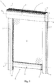
figure 1 shows a front perspective view of the fabric roller blind, object of the present invention; -
figure 2 shows a perspective view of a detail of the blind illustrated infigure 1 , relative to a lateral guideway and to the corresponding lateral end of the bottom bar, with some parts removed or transparent in order to better illustrate other parts; -
figure 3 shows a bottom plan view of the detail of the blind illustrated infigure 2 , with some parts removed in order to better illustrate other parts; -
figure 4 shows a detail of the present blind relative to the bottom bar with some parts transparent in order to better illustrate the internal components of the bottom bar itself; -
figure 5 shows a longitudinal section view of the bottom bar illustrated infigure 4 ; -
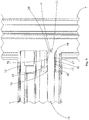
figure 6 shows a detail of the present blind relative to a locking element, with which the corresponding lateral end of the bottom bar is susceptible of being engaged; -
figure 7 shows a sectional lateral view of the locking element illustrated infigure 6 ; -
figures 8a,b,c illustrate a slider element with its guiding portion inserted in the shaped channel of the locking element in different operating positions. - With reference to the enclosed drawings, the fabric roller blind, object of the present invention is indicated overall with the reference number 1.
- The blind 1 can be operatively employed in order to adjustably close an opening A of a door/window/shutter, e.g. of a window, a door or a French window, obtained in a load-bearing element such as a building wall or the load-bearing structure of any building.
- In accordance with the embodiment illustrated in
figure 1 , the blind 1 comprises asupport frame 2 intended to be fixed to the load-bearing element, in which the opening A is obtained, and preferably comprising a rolling-shutter box 3 intended to be positioned above the opening A itself. - Advantageously, the rolling-shutter box 3 comprises a hollow tubular body, in particular obtained with an aluminum extrusion, which is extended with axis substantially horizontal between two opposite ends closed by two lateral caps, in particular made of plastic material.
- The blind 1 also comprises a take-up roller 4 rotatably constrained to the
support frame 2, advantageously housed inside the rolling-shutter box 3, and provided with a rotation axis X that is substantially horizontal. - Around the take-up roller 4, a flexible fabric 5 is susceptible of being wound and unwound; such fabric preferably crosses through a lower slit of the rolling-shutter box 3.
- The fabric 5 can be intended for obtaining a darkening screen, e.g. in substitution of a rolling shutter, of a shading screen for filtering sunlight or for obtaining a mosquito netting. Generally, the fabric 5 can be dedicated to closing the opening of a door/window/shutter in order to protect an internal area from sun and/or from wind and/or, more generally, from the atmospheric conditions of the outside environment.
- The fabric 5, as a function of its different applications, can be made of synthetic or natural material fabric and it can have the form of a mesh or have a continuous surface of obscurant, filtering or transparent type.
- The fabric 5 has a preferably rectangular form and is provided, in a manner per se known to the man skilled in the art, with an upper edge fixed to the take-up roller and with a lower edge fixed to a
bottom bar 6 arranged parallel to the take-up roller 4 and aimed to pull the fabric 5. - The blind 1 also comprises two
lateral guideways 7 extended parallel to one another and alongside one another, among which the fabric 5 is susceptible of sliding following its winding and unwinding around the take-up roller 4. - More in detail, each
lateral guideway 7 is longitudinally extended along a respective first direction of extension Y, preferably vertical and substantially orthogonal to the rotation axis X of the take-up roller 4, between anupper end 8 thereof, preferably arranged at the rolling-shutter box 3, and an oppositelower end 9 intended to be arranged at the lower edge of the opening A, e.g. on a floor or on a windowsill. - The two
lateral guideways 7 are intended to be arranged along corresponding sides of the opening A and to be fixed to the load-bearing element (in which the opening A itself is obtained), e.g. by means of anchorage screws. - Advantageously, with reference to the embodiment illustrated in
figures 2 and3 , eachlateral guideway 7 is preferably obtained by means of extruded metal sections, in particular of aluminum, and is provided with a transverse section with substantially C-shaped form. - In particular, each
lateral guideway 7 is provided with anopen side 10, arranged facing theopen side 10 of the otherlateral guideway 7, and on which alongitudinal slit 11 is obtained in which thebottom bar 6 is slidably constrained. - More in detail, preferably, each
lateral guideway 7 is provided with twolongitudinal walls 12 that are parallel to each other and connected, along a first edge thereof 12', by abase wall 13 and delimiting, along a second edge thereof 12", the aforesaidlongitudinal slit 11 of theopen side 10 of thelateral guideway 7. - The
bottom bar 6 of the blind 1, fixed to the lower edge of the fabric 5, is longitudinally extended along a second direction of extension Z parallel to the rotation axis X of the take-up roller 4, between two lateral ends thereof 14 slidably engaged with the respectivelateral guideways 7. - In particular, the
bottom bar 6 is internally hollow and preferably comprises a metal section 6', e.g. of extruded aluminum. - The lateral ends 14 of the
bottom bar 6 are preferably made of plastic material, they are placed to laterally close the metal section 6' of thebottom bar 6 and are fixed to the latter by means of connection screws, for example. - In particular, each
lateral end 14 of thebottom bar 6 is provided with anenlarged base portion 15, preferably fixed to the metal section 6', and aconnection portion 16 projectingly extended from thebase portion 15 towards the correspondinglateral guideway 7 and slidably inserted in thelongitudinal slit 11 of the latter. - Advantageously, with reference to the embodiment illustrated in
figures 2 and3 , eachlateral guideway 7 of the blind 1 is at its interior provided with alongitudinal seat 17 extended along the first direction of extension Y between theupper end 8 andlower end 9 of thelateral guideway 7 itself. - In particular, inside the
longitudinal seat 17 of eachlateral guideway 7, arail 18 is fixed, preferably made of plastic material, to which a corresponding lateral edge of the fabric 5 is slidably coupled when the latter is moved from the take-up roller 4. - The blind 1 also comprises movement means (not illustrated in the enclosed figures) mechanically connected to the take-up roller 4 and adapted to rotate the latter so as to move the fabric 5 between a collected position, in which the fabric 5 is wound around the take-up roller 4, and an extended position, in which the fabric 5 is unwound from the take-up roller 4 to at least partially close the opening A.
- In particular, when the fabric 5 is in the collected position, the
bottom bar 6 preferably abuts against the rolling-shutter box 3 and, when the fabric 5 is in the extended position, thebottom bar 6 is placed at the lower ends 9 of thelateral guideways 7 with the fabric 5 unwound for the substantially total closure of the opening A. - The fabric 5 is therefore completely guided in its winding and unwinding following the rotation of the take-up roller 4, with its lateral edges engaged in the
rails 18 placed inside thelateral guideways 7, and with the lower edge fixed to thebottom bar 6 in turn engaged in thelateral guideways 7 themselves. - In particular, during the movement of the fabric 5, the
bottom bar 6 keeps the fabric 5 itself stretched and is moved, remaining horizontal, with its lateral ends 14 engaged with thelateral guideways 7. - Preferably, the aforesaid movement means comprise in a per se entirely conventional manner, a motor (not illustrated) housed inside the take-up roller 4 advantageously at one end thereof. Even if, for the purposes of the present invention, the movement means can also be of manual type, and for example obtained by means of an articulated control rod, the motorized embodiment must be intended as being advantageous and undoubtedly preferable.
- In accordance with the idea underlying the present invention, the blind 1 comprises at least one
slider element 19 slidably constrained to thebottom bar 6 and movable along the aforesaid second direction of extension Z. -
Such slider element 19 is provided with anengagement portion 20, passing through the correspondinglateral end 14 of thebottom bar 6 and slidably engaged with the correspondinglateral guideway 7, and with aseparate guiding portion 21 fixed to theengagement portion 20. - In addition, the blind 1 comprises at least one locking
element 22 which is fixed to the respectivelateral guideway 7, preferably in proximity to thelower end 9 of the latter, and is provided with a shapedchannel 23, within which the guidingportion 21 of theslider element 19 is slidably inserted when the fabric 5 is in the extended position; theaforesaid locking element 22 is also provided with anabutment portion 24 susceptible of receiving in abutment theengagement portion 20 of theslider element 19 in order to lock the bottom bar 6 (as described hereinbelow). - More in detail, the shaped
channel 23 of the lockingelement 22 is provided with anaccess section 25, through which the guidingportion 21 of theslider element 19 enters into the shapedchannel 23 following a downward movement of thebottom bar 6 during the unwinding of the fabric 5, and through which the guidingportion 21 of theslider element 19 exits from the shapedchannel 23 following an upward movement of thebottom bar 6 during the winding of the fabric 5. - The shaped
channel 23 of the lockingelement 22 is also provided with astop section 26 arranged for guiding the guidingportion 21 of theslider element 19 to set thecorresponding engagement portion 20 constrained to theabutment portion 24 of the lockingelement 22. - More in detail, the guiding
portion 21 of theslider element 19 is movable within the shapedchannel 23 between theaccess section 25 and thestop section 26 of thechannel 23 itself. - At the
access section 25 of the shapedchannel 23, theslider element 19 is arranged with theengagement portion 20 spaced from theabutment portion 24 of the lockingelement 22 at least along the second direction of extension Z, in order to allow the entrance and exit of the guidingportion 21 without theengagement portion 20 interfering with theabutment portion 24. - At the
stop section 26 of the shapedchannel 23, theslider element 19 is arranged with theengagement portion 20 positioned beneath theabutment portion 24 in abutment against the latter, in order to block the upward ascent of thebottom bar 6 by holding the fabric 5 in the extended position. - In particular, the
stop section 26 of the shapedchannel 23 is preferably extended at least partly vertically and on the upper part is delimited by a terminal wall 26' advantageously positioned at a lower elevation than that of theabutment portion 24 of the lockingelement 22. - The
slider element 19 and the lockingelement 22 of the blind 1 are configured in a manner such that, when theengagement portion 20 of theslider element 19 abuts against theabutment portion 24 of the lockingelement 22, the guidingportion 21 of theslider element 19 is vertically spaced from the terminal wall 26' of thestop section 26 of the shapedchannel 23, such that the upward traction force exerted on thebottom bar 6 is unloaded on theabutment portion 24 of the lockingelement 22 through theengagement portion 20 of theslider element 19, without resting on the guidingportion 21 of the latter. - Advantageously, the present blind 1 comprises two
slider elements 19, associated with the respective lateral ends 14 of thebottom bar 6, and twocorresponding locking elements 22 fixed to the respectivelateral guideways 7 of the blind 1 itself. - In accordance with the embodiment illustrated in
figures 6 and7 , each lockingelement 22 of the blind 1 has a transverse section (with respect to the first direction of extension Y) with substantially C-shaped form, with twoarms 27 parallel to each other and connected by abottom portion 28 directed towards thebase wall 13 of the respectivelateral guideway 7. The twoarms 27 are provided with free ends that together delimit apassage opening 29, facing thelongitudinal slit 11 of thelateral guideway 7, and susceptible of being traversed by theslider element 19 when the fabric 5 is brought into the extended position. - Advantageously, the shaped
channel 23 of each lockingelement 22 is obtained on the inner face of at least one of thearms 27 of the lockingelement 22 itself and preferably on the inner faces of botharms 27. - Advantageously, each locking
element 22 is positioned inside thelongitudinal seat 17 of the correspondinglateral guideway 7 and is preferably fixed to thebase wall 13 of theguideway 7 itself. - In particular, each locking
element 22 is fixed to thebase wall 13 of the correspondinglateral guideway 7 preferably by means of a fixingscrew 30 inserted into a through hole of thebottom portion 28 of the lockingelement 22 itself. - In particular, each locking
element 22 is advantageously made of plastic material and comprises two half-parts 22', 22", with substantially L-shaped section, fixed to each other, preferably by means of the aforesaid fixingscrew 30, with partial superimposition of the legs of the half-parts which constitute thebottom portion 28 of the lockingelement 22 itself. - In particular, with reference to the embodiment illustrated in
figures 6 and7 , each lockingelement 22 is provided with arear side 31, closed by thebottom portion 28, and with afront side 32 on which the aforesaid passage opening 29 is obtained. - In accordance with the embodiment illustrated in
figure 7 , theaccess section 25 of the shapedchannel 23 of each lockingelement 22 is provided with alower wall 33 susceptible of receiving in abutment the guidingportion 21 of theslider element 19 when thebottom bar 6 is moved downward following the unwinding of the fabric 5 from the take-up roller 4. - The aforesaid
lower wall 33, following the descent of thebottom bar 6, guides the guidingportion 21 of theslider element 19 to a lowerend stop section 34 of the shapedchannel 23 with preferably concave shape, the descent of thebottom bar 6 being stopped atsuch section 34. - More in detail, the
lower part 33 of theaccess section 25 of the shapedchannel 23 is extended tilted downward from thefront side 32 of the lockingelement 22 towards therear side 31 of the latter. In this manner, following the descent of thebottom bar 6, the guidingportion 21 of theslider element 19 slides on thelower wall 33 towards therear side 31 of the lockingelement 22 until it is stopped in the lowerend stop section 34, arranging theengagement portion 20 of theslider element 19 below theabutment portion 24 of the lockingelement 22 vertically spaced from theabutment portion 24 itself. - Advantageously, the shaped
channel 23 is also provided with aconnector section 35, placed to connect between the lowerend stop section 34 and thestop section 26, and through which the guidingportion 21 of theslider element 19, following an ascending movement of thebottom bar 6, is moved from the lowerend stop section 34 to thestop section 26 until theengagement portion 20 of theslider element 19 abuts against theabutment portion 24 of the lockingelement 22. - In addition, the shaped
channel 23 is provided with atransmission section 36, preferably with concave shape, and susceptible, during the release of thebottom bar 6, to receive in abutment the guidingportion 21 coming from thestop section 26 following a descending movement of thebottom bar 6 itself.Such transmission section 36 is provided with a tilted surface 36' arranged for bringing the guidingportion 21 towards thefront side 32 of the lockingelement 22 in a manner so as to move such guidingportion 21 from beneath thestop section 26. In this manner, a subsequent upward movement of thebottom bar 6 prevents the guidingportion 21 from returning into thestop section 26. Advantageously, theaccess section 25 of the shapedchannel 23 is provided with anupper wall 37 partially facing the cavity of thetransmission section 36 in a manner such that, following an upward movement of thebottom bar 6, suchupper wall 37 receives in abutment the guidingportion 21, guiding it towards thefront side 32 of the lockingelement 22 until it is made to exit from the shapedchannel 23. - In particular, the
upper wall 37 of theaccess section 25 is extended tilted upward from thetransmission section 36 to thefront side 32 of the lockingelement 22 in a manner so as to guide the guidingportion 21 of theslider element 19 outside the shapedchannel 23 following an ascending movement of the bottom bar. - Advantageously, each locking
element 22 comprises aguide portion 38 projectingly extended from thefront side 32 of the lockingelement 22 itself as an extension of thelower wall 33 of theaccess section 25 of the corresponding shapedchannel 23, and adapted to receive in abutment the guidingportion 21 of theslider element 19, guiding it into theaccess section 25 of the shapedchannel 23 itself. - Preferably, the
stop portion 24 of each lockingelement 22 is arranged at a greater height than that of thestop section 26 of the shapedchannel 23, and is in particular obtained with a transverse rod fixed between the twoarms 27 of the lockingelement 22 itself. - Advantageously, in accordance with the embodiment illustrated in
figures 2 and4 , eachslider element 19 of the blind 1 has elongated shape (preferably rod-like) along the second direction of extension Z of thebottom bar 6, extended between an inner end 39, arranged inside the metal section 6' of thebottom bar 6, and anouter end 40 at which thecorresponding engagement portion 20 is arranged. - In particular, the
engagement portion 20 of eachslider element 19 is extended outside thebottom bar 6, projecting from thebase portion 15 of the correspondinglateral end 14, and is preferably parallel to theconnection portion 16 of thelateral end 14, being inserted in thelongitudinal seat 17 of the correspondinglateral guideway 7 passing through thelongitudinal slit 11 of the latter. - The
engagement portion 20 of eachslider element 19 is preferably integrally made with the rod-like body of theslider element 19 itself and preferably has a width of about 10 mm. - Advantageously, the guiding
portion 21 of eachslider element 19 is extended transverse to the second direction of extension Z of thebottom bar 6 and transverse to the first direction of extension Y of thelateral guideways 7. - In particular, the guiding
portion 21 is projectingly extended from theengagement portion 20 orthogonal to the longitudinal extension of thecorresponding slider element 19. - Preferably the guiding
portion 21 is extended from two opposite sides of theengagement portion 20 of thecorresponding slider element 19, in particular orthogonal to thearms 27 of thecorresponding locking element 22 fixed to thelateral guideway 7. - In accordance with the particular embodiment illustrated in
figures 4 and5 , the guidingportion 21 of eachslider element 19 is obtained with a rod which is arranged transverse to the rod-like body of theslider element 19 itself, is inserted into acorresponding connection hole 41 obtained in theengagement portion 20, and preferably has a width of about 2-3 mm. - Advantageously, still with reference to the embodiment illustrated in
figures 4 and5 , eachlateral end 14 of thebottom bar 6 is provided with a first throughhole 42 in which thecorresponding slider element 19 is slidably inserted. - Preferably, the aforesaid first through
hole 42 is partly extended into thebase portion 15 and partly extended into theconnection portion 16 of the correspondinglateral end 14 of thebottom bar 6. - Advantageously, the present blind 1 comprises two guiding
elements 43, each of which is slidably engaged with thebottom bar 6 at the respectivelateral end 14 of thebottom bar 6 itself and movable along the second direction of extension Z of the latter. - More in detail, each guiding
element 43 is provided with afront portion 44 slidably inserted into thelongitudinal slit 11 of the correspondinglateral guideway 7. - Elastic means 45 are also provided, interposed between the
bottom bar 6 and the corresponding guidingelement 43 and arranged for pushing such guidingelement 43 towards the correspondinglateral guideway 7 along the second direction of extension Z in order to maintain thefront portion 44 of the guidingelement 43 inserted in thelongitudinal slit 11 of thelateral guideway 7. - Preferably, each guiding
element 43 is slidably inserted into the first throughhole 42 of the correspondinglateral end 14 of thebottom bar 6, and also thecorresponding slider element 19 is inserted in suchfirst hole 42. - In particular, each guiding
element 43 has tubular form extended along the second direction of extension Z between arear end 46, preferably arranged inside thebottom bar 6, and the aforesaidfront end 44 inserted in thelongitudinal slit 11 of the correspondinglateral guideway 7. - Preferably, each guiding
element 43 is provided with a second throughhole 47 in which thecorresponding slider element 19 is slidably inserted, in a manner so as to allow the sliding thereof. - Advantageously, at least when the guiding
portion 21 of eachslider element 19 is outside the shapedchannel 23 of thecorresponding locking element 22, the corresponding guidingelement 43 is arranged in abutment againstsuch slider element 19, pushing the guidingportion 21 of the latter inside thelongitudinal slit 11 of the correspondinglateral guideway 7, in a manner so as to allow the guidingportion 21 to enter into the shapedchannel 23 of the lockingelement 22 when the fabric 5 is brought into the extended position. - More in detail, preferably, each guiding
element 43 is placed in abutment against the guidingportion 21 of thecorresponding slider element 19, pushing the latter towards the correspondinglateral guideway 7. - Advantageously, the elastic means 45 are arranged for pushing the corresponding guiding
element 43 in abutment against theopen side 10 of the correspondinglateral guideway 7. In particular, each guidingelement 43 is provided with anabutment shoulder 48 thrust against thesecond edges 12" of thelongitudinal walls 12 of thelateral guideway 7 itself. - Preferably, the elastic means 45 comprise a
helical spring 49, in particular arranged around the correspondingslider element 19 and compressed between a firstinner shoulder 50 obtained in the bottom bar and a secondinner shoulder 51 obtained in the corresponding guidingelement 43. - In operation, when the fabric 5 of the blind 1 is brought from the collected position to the extended position, the motor actuates the take-up roller 4 to rotate in a first rotation sense, unwinding the fabric 5 from the roller 4 itself and allowing the
bottom bar 6 to descend along thelateral guideways 7 to thelocking elements 22. - With reference to the example of
figure 8a , when the lateral ends 14 of thebottom bar 6 reach thecorresponding locking elements 22, the guidingportion 21 of eachslider element 19 abuts against theguide portion 38 of thecorresponding locking element 22, which brings the guidingelement 21 to enter into theaccess section 25 of the shapedchannel 23 by sliding on thelower wall 33 of the latter. - Following the descending movement of the
bottom bar 6, thelower wall 33 of the shapedchannel 23 brings the corresponding guidingelement 21 to the lowerend stop section 34 of thechannel 23 itself, and atsuch section 34 the motor stops the rotation of the take-up roller 4. - Advantageously, the motor of the blind 1 is provided with a programmed control unit, in a manner per se known to the man skilled in the art, in order to make the take-up roller 4 execute a specific number of revolutions in the aforesaid first rotation sense, as a function in particular of the length of the
lateral guideways 7, in a manner so as to stop the movement of the take-up roller 4, and hence the descent of thebottom bar 6, when the guidingportion 21 of eachslider element 19 has reached the lowerend stop section 34 of the shapedchannel 23 of thecorresponding locking element 22, preferably with a specific over-travel of, for example, several millimeters. - Subsequently, the motor actuates the take-up roller to rotate in a second rotation direction, opposite the first, in a manner so as to pull the
bottom bar 6 upward. Consequently, with reference to the embodiment offigure 8b , the guidingportion 21 of eachslider element 19 is brought to slide in the shapedchannel 23 from the lowerend stop section 34 to thestop section 26, passing through theconnector section 35, until theengagement portion 20 of the slider element abuts against theabutment portion 24 of thecorresponding locking element 22, stopping the ascending movement of thebottom bar 6 in a manner so as to pull the fabric 5 into the extended position between the take-up roller 4 and thebottom bar 6 itself. - Preferably, when the
engagement portions 20 of theslider elements 19 abut against theabutment portions 24 of thecorresponding locking elements 22, the motor increases the generated force with a consequent increase of the absorbed energy until a specific absorption threshold value is reached, beyond which the motor is programmed to be stopped. - In order to release
bottom bar 6 and bring the fabric 5 back into the retracted position, the motor is controlled to rotate the take-up roller 4 in the first rotation sense in order to make thebottom bar 6 descend. Consequently, the guidingportion 21 of eachslider element 19 descends from thestop section 26 to thetransmission section 36 of the corresponding shapedchannel 23, in particular falling on the tilted surface 36' of theaforesaid transmission section 36 which brings the guidingportion 21 towards thefront side 32 of the lockingelement 22 in a manner such to move the guidingportion 21 from beneath thestop section 26, bringing it beneath theupper wall 37 of theaccess section 25 of the shapedchannel 23. - Then, the control unit controls the motor to be stopped and, subsequently, to drive the take-up roller 4 to rotate in the second rotation sense in order to pull the
bottom bar 6 upward. Consequently, with reference to the embodiment illustrated infigure 8c , the guidingportion 21 of eachslider element 19 is brought into abutment against theupper wall 37 of theaccess section 25 of the corresponding shapedchannel 23, which, following the ascending movement of thebottom bar 6, brings the guidingportion 21 towards thefront side 32 of thecorresponding locking element 22, in a manner so as to move theengagement portion 20 of theslider element 19 from below theabutment portion 24 of the lockingelement 22 itself. In this manner, the guidingportion 21 exits from the corresponding shapedchannel 23 without theengagement portion 20 interfering with theabutment portion 24 of the lockingelement 22, allowing thebottom bar 6 to ascend towards the take-up roller 4 until the fabric 5 is brought into its retracted position wound around the roller 4 itself. - In accordance with a different embodiment, in which the take-up roller 4 is manually actuated by a user, the above-described descending and ascending movements of the
bottom bar 6 are controlled by the user himself, for example by means of an articulated control rod. - The invention thus conceived therefore attains the pre-established objects.
- In particular, the
slider elements 19 of the blind 1 according to the invention, provided with guidingportions 21 separate from theengagement portions 20 intended to be coupled to thecorresponding locking elements 22, allow loading the locking force, to which thebottom bar 6 is subjected when it is locked, on theengagement portion 20 and not on the guidingportion 21. This allows obtaining the guidingportion 21 of theslider elements 19 of small size with respect to theengagement portion 20, allowing the obtainment of the shapedchannels 23 of equally small size within the lockingelements 22, determining a compact size of the latter. Consequently, it is possible to arrange thelocking elements 22 inlateral guideways 7 of compact size, and in particular in the guideways of standard size present on the market, also employed for blinds that are not equipped with automatic locking systems for the bottom bar. - In addition, the arrangement of the locking
elements 22 according to the invention inside thelongitudinal seats 17 of the correspondinglateral guideways 7, allows, during installation, adjustably arranging the height of the lockingelements 22. In this manner, it is possible to arrange the two lockingelements 22 at the same distance from the take-up roller 4 even in the presence of floor elevation differences, ensuring equal tightening along both the lateral edges of the fabric 5 when it is in the extended position. - In addition, the guiding
element 43, associated with eachlateral end 14 of thebottom bar 6 of the blind 1 according to the invention, allows maintaining thebottom bar 6 correctly engaged with thelateral guideways 7 even in conditions in which the latter are not exactly parallel, such as for example in the presence of walls that are not perfectly vertical. - In addition, the guiding
element 43, acting on thecorresponding slider element 19, allows maintaining theengagement portion 20 of the latter within the correspondinglateral guideway 7, ensuring the correct insertion of the guidingportion 21 of theslider element 19 in the shapedchannel 23 of thecorresponding locking element 22 when thebottom bar 6 is brought to the latter.
Claims (11)
- A fabric roller blind (1), which comprises:- a support frame (2) intended to be fixed to a load-bearing element in which an opening (A) is obtained;- a take-up roller (4) rotatably constrained to said support frame (2), having a rotation axis (X) that is substantially horizontal, and intended to be positioned above said opening (A);- two lateral guideways (7) extended parallel to one another and alongside one another along respective first directions of extension (Y) substantially orthogonal to the rotation axis (X) of said take-up roller (4), and intended to be fixed to said load-bearing element along respective sides of said opening (A);- a fabric (5) extended between an upper edge thereof fixed to said take-up roller (4) and a lower edge thereof, and susceptible of sliding between said lateral guideways (7);- a bottom bar (6) fixed to the lower edge of said fabric (5) and extended, along a second direction of extension (Z) parallel to the rotation axis (X) of said take-up roller (4), between two lateral ends thereof (14) slidably engaged with the corresponding lateral guideways (7);- movement means mechanically connected to said take-up roller (4) and adapted to rotate said take-up roller (4) so as to move said fabric (5) between a retracted position, in which said fabric (5) is wound around said take-up roller (4), and an extended position, in which said fabric (5) is at least partially unwound from said take-up roller (4) extended between said lateral guideways (7) to cover at least part of said opening (A);- at least one slider element (19), which is slidably constrained to said bottom bar (6), is movable along said second direction of extension (Z), and is provided with an engagement portion (20), passing through the corresponding lateral end (14) of said bottom bar (6) and slidably engaged with the corresponding lateral guideway (7), and with a guiding portion (21) fixed to said engagement portion (20);- at least one locking element (22) which is fixed to the corresponding lateral guideway (7), characterised in that the locking element is provided with:- a shaped channel (23) within which the guiding portion (21) of said at least one slider element (19) is slidably inserted with said fabric (5) in said extended position,- and an abutment portion (24) susceptible of receiving said engagement portion (20) in abutment; and in that the guiding portion (21) of said at least one slider element (19) is movable in said shaped channel (23) between an access section (25) of said shaped channel (23), at which access section (25) said slider element (19) is arranged with said engagement portion (20) spaced from said abutment portion (24) at least along said second direction of extension (Z), and a stop section (26) of said shaped channel (23), at which stop section (26) said slider element (19) is arranged with said engagement portion (20) positioned beneath said abutment portion (24) in abutment against the latter.
- Blind (1) according to claim 1, characterized in that the guiding portion (21) of said slider element (19) is extended substantially transverse to said first direction of extension (Y) and to said second direction of extension (Z).
- Blind (1) according to claim 1 or 2, characterized in that said slider element (19) has elongated shape along said second direction of extension (Z) and is extended between an inner end (39), arranged inside said bottom bar (6), and an outer end (40) positioned outside said bottom bar (6) and at which said engagement portion (20) is arranged.
- Blind (1) according to any one of the preceding claims, characterized in that the lateral end (14) of said bottom bar (6) is provided with a first through hole (42) in which said slider element (19) is slidably inserted.
- Blind (1) according to any one of the preceding claims, wherein each said lateral guideway (7) is provided with an open side (10), facing the open side (10) of the other said lateral guideway (7), a longitudinal slit (11) obtained on such open side (10) into which the corresponding lateral end (14) of said bottom bar (6) is at least partially inserted;
said blind (1) being characterized in that it comprises:- at least one guiding element (43) slidably engaged with the corresponding lateral end (14) of said bottom bar (6) and movable along said second direction of extension (Z), and provided with a front portion (44) slidably inserted into the longitudinal slit (11) of said lateral guideway (7);- elastic means (45) interposed between said bottom bar (6) and said guiding element (43) and arranged for pushing said guiding element (43) towards the corresponding said lateral guideway (7) with said front portion (44) inserted into said longitudinal slit (11). - Blind (1) according to claims 4 and 5, characterized in that said guiding element (43) is slidably inserted into the first through hole (42) of the corresponding lateral end (14) of said bottom bar (6).
- Blind (1) according to claim 5 or 6, characterized in that said guiding element (43), at least with the guiding portion (21) of said slider element (19) positioned outside said shaped channel (23), is arranged in abutment against said slider element (19), pushing the engagement portion (20) of said slider element (19) inside the longitudinal slit (11) of the corresponding said lateral guideway (7).
- Blind (1) according to claim 7, characterized in that said guiding element (43) is placed in abutment against the guiding portion (21) of said slider element (19) arranged outside the shaped channel (23) of said locking element (22).
- Blind (1) according to any one of the preceding claims, characterized in that each said lateral guideway (7) is provided with a longitudinal seat (17) extended along said first direction of extension (Y), said locking element (22) positioned inside such longitudinal seat (17).
- Blind (1) according to any one of the preceding claims, characterized in that said locking element (22) is provided with a front side (32), in which at least one passage opening (29) is obtained that is susceptible of being traversed by said slider element (19) with said fabric (5) in said extended position, and comprises a guide portion (38) projectingly extended from said front side (32) as an extension of a lower wall (33) of the access section (25) of said shaped channel (23), and adapted to receive in abutment the guiding portion (21) of said slider element (19), guiding it into said shaped channel (23).
- Blind (1) according to any one of the preceding claims, characterized in that the guiding portion (21) of said slider element (19) has size substantially smaller than that of the engagement portion (20) of said slider element (19).
Applications Claiming Priority (1)
| Application Number | Priority Date | Filing Date | Title |
|---|---|---|---|
| ITPD20140246 | 2014-09-24 |
Publications (2)
| Publication Number | Publication Date |
|---|---|
| EP3000958A1 EP3000958A1 (en) | 2016-03-30 |
| EP3000958B1 true EP3000958B1 (en) | 2017-05-17 |
Family
ID=51951942
Family Applications (1)
| Application Number | Title | Priority Date | Filing Date |
|---|---|---|---|
| EP15186702.5A Active EP3000958B1 (en) | 2014-09-24 | 2015-09-24 | Fabric roller blind |
Country Status (1)
| Country | Link |
|---|---|
| EP (1) | EP3000958B1 (en) |
Families Citing this family (8)
| Publication number | Priority date | Publication date | Assignee | Title |
|---|---|---|---|---|
| US20160032646A1 (en) * | 2013-03-15 | 2016-02-04 | Jacob Fleischman | Retractable wall system and adaptor components |
| US10273750B2 (en) | 2013-03-15 | 2019-04-30 | Jacob Fleischman | Roll-up wall system and modular components |
| WO2015176047A1 (en) | 2014-05-15 | 2015-11-19 | Fleischman Jacob | Roll-up wall and acoustic barrier system |
| WO2018200875A1 (en) | 2017-04-26 | 2018-11-01 | Joel Klein | Modular roll-up wall system |
| IT201800009261A1 (en) | 2018-10-08 | 2020-04-08 | Palagina Srl | TENT WITH ROLLING CANVAS |
| SI25575A (en) * | 2019-03-13 | 2019-06-28 | Roletarstvo Medle d.o.o. | Against burglary mechanism for roller shutters and methods in connection with it |
| CN211746454U (en) * | 2020-03-04 | 2020-10-27 | 刘英杰 | Mosquito repelling device |
| WO2023118444A1 (en) * | 2021-12-23 | 2023-06-29 | Corradi S.R.L. | A retractable screen construction |
Family Cites Families (4)
| Publication number | Priority date | Publication date | Assignee | Title |
|---|---|---|---|---|
| IT1394671B1 (en) * | 2009-07-14 | 2012-07-13 | Fanani S R L | LOCKING GROUP, PARTICULARLY FOR OUTDOOR CURTAINS. |
| ITPR20110097A1 (en) | 2011-11-25 | 2013-05-26 | Arquati Group S R L | OPENING AND CLOSING STRUCTURE OF A PASSAGE |
| ITBO20120024U1 (en) * | 2012-02-22 | 2013-08-23 | Corradi S P A | GUIDE GROUP, FOR CURTAINS, OUTDOOR TENDONS AND SIMILAR DEVICES |
| ITBO20120503A1 (en) * | 2012-09-21 | 2014-03-22 | Fanani S R L | LOCKING DEVICE, FOR CURTAINS, MOBILE WALLS, MOSQUITO NETS AND THE LIKE. |
-
2015
- 2015-09-24 EP EP15186702.5A patent/EP3000958B1/en active Active
Also Published As
| Publication number | Publication date |
|---|---|
| EP3000958A1 (en) | 2016-03-30 |
Similar Documents
| Publication | Publication Date | Title |
|---|---|---|
| EP3000958B1 (en) | Fabric roller blind | |
| US9670721B2 (en) | Guide arrangement for hangings | |
| US6186215B1 (en) | Multi-positional rolling window screen | |
| EP2236731B1 (en) | Covering arrangement for architectural openings | |
| EP3431698B1 (en) | Fabric roller blind | |
| CA2834099C (en) | Cordless blind systems having cord enclosures with a swivel feature and methods of assembling such cord enclosures | |
| EP2982827A1 (en) | Roller awning | |
| US20160069130A1 (en) | Cordless blind system and retro-fit method | |
| US20090242141A1 (en) | Mosquito curtain for rolling shutters or window openings | |
| EP3312376B1 (en) | Roller blind | |
| EP3249148B1 (en) | Fabric roller blind | |
| EP3636872B1 (en) | Fabric roller blind | |
| KR101195828B1 (en) | Winding apparatus for blind | |
| KR101133450B1 (en) | Blind for shading | |
| EP3511513B1 (en) | Fabric roller blind | |
| EP3567205B1 (en) | Guide chain for fabric roller blind | |
| EP3875729B1 (en) | Insect screen system with devices for fast assembly and anchorage of a box in a space for a frame | |
| EP4041978B1 (en) | Roller shutter with orientable slats provided with a simplified means for angular rotation | |
| EP3670817B1 (en) | Roller blind with support device for the winding roller | |
| KR20160148241A (en) | a Screen which is wound up like a Roll, And Screen Production Device And Method Thereof | |
| JP2591164Y2 (en) | Window blinds | |
| PL237747B1 (en) | Jalousie, preferably the external jalousie | |
| PL229645B1 (en) | External shutter for a roof window | |
| IT201600104881A1 (en) | CURTAIN WITH ROLLER SHUTTER AND METHOD OF OPERATION OF THAT CURTAIN WITH ROLLER TABLE | |
| GB2501797A (en) | Screen Assembly |
Legal Events
| Date | Code | Title | Description |
|---|---|---|---|
| PUAI | Public reference made under article 153(3) epc to a published international application that has entered the european phase |
Free format text: ORIGINAL CODE: 0009012 |
|
| AK | Designated contracting states |
Kind code of ref document: A1 Designated state(s): AL AT BE BG CH CY CZ DE DK EE ES FI FR GB GR HR HU IE IS IT LI LT LU LV MC MK MT NL NO PL PT RO RS SE SI SK SM TR |
|
| AX | Request for extension of the european patent |
Extension state: BA ME |
|
| 17P | Request for examination filed |
Effective date: 20160927 |
|
| RBV | Designated contracting states (corrected) |
Designated state(s): AL AT BE BG CH CY CZ DE DK EE ES FI FR GB GR HR HU IE IS IT LI LT LU LV MC MK MT NL NO PL PT RO RS SE SI SK SM TR |
|
| GRAP | Despatch of communication of intention to grant a patent |
Free format text: ORIGINAL CODE: EPIDOSNIGR1 |
|
| RIC1 | Information provided on ipc code assigned before grant |
Ipc: E06B 9/42 20060101ALI20161124BHEP Ipc: E06B 9/80 20060101ALN20161124BHEP Ipc: E06B 9/58 20060101AFI20161124BHEP |
|
| INTG | Intention to grant announced |
Effective date: 20161208 |
|
| GRAS | Grant fee paid |
Free format text: ORIGINAL CODE: EPIDOSNIGR3 |
|
| GRAA | (expected) grant |
Free format text: ORIGINAL CODE: 0009210 |
|
| AK | Designated contracting states |
Kind code of ref document: B1 Designated state(s): AL AT BE BG CH CY CZ DE DK EE ES FI FR GB GR HR HU IE IS IT LI LT LU LV MC MK MT NL NO PL PT RO RS SE SI SK SM TR |
|
| REG | Reference to a national code |
Ref country code: GB Ref legal event code: FG4D |
|
| REG | Reference to a national code |
Ref country code: CH Ref legal event code: EP |
|
| REG | Reference to a national code |
Ref country code: IE Ref legal event code: FG4D |
|
| REG | Reference to a national code |
Ref country code: AT Ref legal event code: REF Ref document number: 894643 Country of ref document: AT Kind code of ref document: T Effective date: 20170615 |
|
| REG | Reference to a national code |
Ref country code: DE Ref legal event code: R096 Ref document number: 602015002753 Country of ref document: DE |
|
| REG | Reference to a national code |
Ref country code: NL Ref legal event code: MP Effective date: 20170517 |
|
| REG | Reference to a national code |
Ref country code: FR Ref legal event code: PLFP Year of fee payment: 3 |
|
| REG | Reference to a national code |
Ref country code: LT Ref legal event code: MG4D |
|
| REG | Reference to a national code |
Ref country code: AT Ref legal event code: MK05 Ref document number: 894643 Country of ref document: AT Kind code of ref document: T Effective date: 20170517 |
|
| PG25 | Lapsed in a contracting state [announced via postgrant information from national office to epo] |
Ref country code: NO Free format text: LAPSE BECAUSE OF FAILURE TO SUBMIT A TRANSLATION OF THE DESCRIPTION OR TO PAY THE FEE WITHIN THE PRESCRIBED TIME-LIMIT Effective date: 20170817 Ref country code: HR Free format text: LAPSE BECAUSE OF FAILURE TO SUBMIT A TRANSLATION OF THE DESCRIPTION OR TO PAY THE FEE WITHIN THE PRESCRIBED TIME-LIMIT Effective date: 20170517 Ref country code: LT Free format text: LAPSE BECAUSE OF FAILURE TO SUBMIT A TRANSLATION OF THE DESCRIPTION OR TO PAY THE FEE WITHIN THE PRESCRIBED TIME-LIMIT Effective date: 20170517 Ref country code: AT Free format text: LAPSE BECAUSE OF FAILURE TO SUBMIT A TRANSLATION OF THE DESCRIPTION OR TO PAY THE FEE WITHIN THE PRESCRIBED TIME-LIMIT Effective date: 20170517 Ref country code: ES Free format text: LAPSE BECAUSE OF FAILURE TO SUBMIT A TRANSLATION OF THE DESCRIPTION OR TO PAY THE FEE WITHIN THE PRESCRIBED TIME-LIMIT Effective date: 20170517 Ref country code: FI Free format text: LAPSE BECAUSE OF FAILURE TO SUBMIT A TRANSLATION OF THE DESCRIPTION OR TO PAY THE FEE WITHIN THE PRESCRIBED TIME-LIMIT Effective date: 20170517 Ref country code: GR Free format text: LAPSE BECAUSE OF FAILURE TO SUBMIT A TRANSLATION OF THE DESCRIPTION OR TO PAY THE FEE WITHIN THE PRESCRIBED TIME-LIMIT Effective date: 20170818 |
|
| PG25 | Lapsed in a contracting state [announced via postgrant information from national office to epo] |
Ref country code: IS Free format text: LAPSE BECAUSE OF FAILURE TO SUBMIT A TRANSLATION OF THE DESCRIPTION OR TO PAY THE FEE WITHIN THE PRESCRIBED TIME-LIMIT Effective date: 20170917 Ref country code: SE Free format text: LAPSE BECAUSE OF FAILURE TO SUBMIT A TRANSLATION OF THE DESCRIPTION OR TO PAY THE FEE WITHIN THE PRESCRIBED TIME-LIMIT Effective date: 20170517 Ref country code: LV Free format text: LAPSE BECAUSE OF FAILURE TO SUBMIT A TRANSLATION OF THE DESCRIPTION OR TO PAY THE FEE WITHIN THE PRESCRIBED TIME-LIMIT Effective date: 20170517 Ref country code: RS Free format text: LAPSE BECAUSE OF FAILURE TO SUBMIT A TRANSLATION OF THE DESCRIPTION OR TO PAY THE FEE WITHIN THE PRESCRIBED TIME-LIMIT Effective date: 20170517 Ref country code: PL Free format text: LAPSE BECAUSE OF FAILURE TO SUBMIT A TRANSLATION OF THE DESCRIPTION OR TO PAY THE FEE WITHIN THE PRESCRIBED TIME-LIMIT Effective date: 20170517 Ref country code: NL Free format text: LAPSE BECAUSE OF FAILURE TO SUBMIT A TRANSLATION OF THE DESCRIPTION OR TO PAY THE FEE WITHIN THE PRESCRIBED TIME-LIMIT Effective date: 20170517 Ref country code: BG Free format text: LAPSE BECAUSE OF FAILURE TO SUBMIT A TRANSLATION OF THE DESCRIPTION OR TO PAY THE FEE WITHIN THE PRESCRIBED TIME-LIMIT Effective date: 20170817 |
|
| PG25 | Lapsed in a contracting state [announced via postgrant information from national office to epo] |
Ref country code: EE Free format text: LAPSE BECAUSE OF FAILURE TO SUBMIT A TRANSLATION OF THE DESCRIPTION OR TO PAY THE FEE WITHIN THE PRESCRIBED TIME-LIMIT Effective date: 20170517 Ref country code: CZ Free format text: LAPSE BECAUSE OF FAILURE TO SUBMIT A TRANSLATION OF THE DESCRIPTION OR TO PAY THE FEE WITHIN THE PRESCRIBED TIME-LIMIT Effective date: 20170517 Ref country code: SK Free format text: LAPSE BECAUSE OF FAILURE TO SUBMIT A TRANSLATION OF THE DESCRIPTION OR TO PAY THE FEE WITHIN THE PRESCRIBED TIME-LIMIT Effective date: 20170517 Ref country code: RO Free format text: LAPSE BECAUSE OF FAILURE TO SUBMIT A TRANSLATION OF THE DESCRIPTION OR TO PAY THE FEE WITHIN THE PRESCRIBED TIME-LIMIT Effective date: 20170517 Ref country code: DK Free format text: LAPSE BECAUSE OF FAILURE TO SUBMIT A TRANSLATION OF THE DESCRIPTION OR TO PAY THE FEE WITHIN THE PRESCRIBED TIME-LIMIT Effective date: 20170517 |
|
| REG | Reference to a national code |
Ref country code: DE Ref legal event code: R097 Ref document number: 602015002753 Country of ref document: DE |
|
| PG25 | Lapsed in a contracting state [announced via postgrant information from national office to epo] |
Ref country code: SM Free format text: LAPSE BECAUSE OF FAILURE TO SUBMIT A TRANSLATION OF THE DESCRIPTION OR TO PAY THE FEE WITHIN THE PRESCRIBED TIME-LIMIT Effective date: 20170517 |
|
| PLBE | No opposition filed within time limit |
Free format text: ORIGINAL CODE: 0009261 |
|
| STAA | Information on the status of an ep patent application or granted ep patent |
Free format text: STATUS: NO OPPOSITION FILED WITHIN TIME LIMIT |
|
| 26N | No opposition filed |
Effective date: 20180220 |
|
| PG25 | Lapsed in a contracting state [announced via postgrant information from national office to epo] |
Ref country code: SI Free format text: LAPSE BECAUSE OF FAILURE TO SUBMIT A TRANSLATION OF THE DESCRIPTION OR TO PAY THE FEE WITHIN THE PRESCRIBED TIME-LIMIT Effective date: 20170517 Ref country code: MC Free format text: LAPSE BECAUSE OF FAILURE TO SUBMIT A TRANSLATION OF THE DESCRIPTION OR TO PAY THE FEE WITHIN THE PRESCRIBED TIME-LIMIT Effective date: 20170517 |
|
| REG | Reference to a national code |
Ref country code: IE Ref legal event code: MM4A |
|
| PG25 | Lapsed in a contracting state [announced via postgrant information from national office to epo] |
Ref country code: LU Free format text: LAPSE BECAUSE OF NON-PAYMENT OF DUE FEES Effective date: 20170924 |
|
| PG25 | Lapsed in a contracting state [announced via postgrant information from national office to epo] |
Ref country code: IE Free format text: LAPSE BECAUSE OF NON-PAYMENT OF DUE FEES Effective date: 20170924 |
|
| REG | Reference to a national code |
Ref country code: FR Ref legal event code: PLFP Year of fee payment: 4 |
|
| PG25 | Lapsed in a contracting state [announced via postgrant information from national office to epo] |
Ref country code: MT Free format text: LAPSE BECAUSE OF NON-PAYMENT OF DUE FEES Effective date: 20170924 |
|
| REG | Reference to a national code |
Ref country code: CH Ref legal event code: PL |
|
| PG25 | Lapsed in a contracting state [announced via postgrant information from national office to epo] |
Ref country code: HU Free format text: LAPSE BECAUSE OF FAILURE TO SUBMIT A TRANSLATION OF THE DESCRIPTION OR TO PAY THE FEE WITHIN THE PRESCRIBED TIME-LIMIT; INVALID AB INITIO Effective date: 20150924 |
|
| PG25 | Lapsed in a contracting state [announced via postgrant information from national office to epo] |
Ref country code: LI Free format text: LAPSE BECAUSE OF NON-PAYMENT OF DUE FEES Effective date: 20180930 Ref country code: CH Free format text: LAPSE BECAUSE OF NON-PAYMENT OF DUE FEES Effective date: 20180930 |
|
| PG25 | Lapsed in a contracting state [announced via postgrant information from national office to epo] |
Ref country code: CY Free format text: LAPSE BECAUSE OF FAILURE TO SUBMIT A TRANSLATION OF THE DESCRIPTION OR TO PAY THE FEE WITHIN THE PRESCRIBED TIME-LIMIT Effective date: 20170517 |
|
| PG25 | Lapsed in a contracting state [announced via postgrant information from national office to epo] |
Ref country code: MK Free format text: LAPSE BECAUSE OF FAILURE TO SUBMIT A TRANSLATION OF THE DESCRIPTION OR TO PAY THE FEE WITHIN THE PRESCRIBED TIME-LIMIT Effective date: 20170517 |
|
| PG25 | Lapsed in a contracting state [announced via postgrant information from national office to epo] |
Ref country code: TR Free format text: LAPSE BECAUSE OF FAILURE TO SUBMIT A TRANSLATION OF THE DESCRIPTION OR TO PAY THE FEE WITHIN THE PRESCRIBED TIME-LIMIT Effective date: 20170517 |
|
| PG25 | Lapsed in a contracting state [announced via postgrant information from national office to epo] |
Ref country code: PT Free format text: LAPSE BECAUSE OF FAILURE TO SUBMIT A TRANSLATION OF THE DESCRIPTION OR TO PAY THE FEE WITHIN THE PRESCRIBED TIME-LIMIT Effective date: 20170517 |
|
| PG25 | Lapsed in a contracting state [announced via postgrant information from national office to epo] |
Ref country code: AL Free format text: LAPSE BECAUSE OF FAILURE TO SUBMIT A TRANSLATION OF THE DESCRIPTION OR TO PAY THE FEE WITHIN THE PRESCRIBED TIME-LIMIT Effective date: 20170517 |
|
| GBPC | Gb: european patent ceased through non-payment of renewal fee |
Effective date: 20190924 |
|
| PG25 | Lapsed in a contracting state [announced via postgrant information from national office to epo] |
Ref country code: GB Free format text: LAPSE BECAUSE OF NON-PAYMENT OF DUE FEES Effective date: 20190924 |
|
| P01 | Opt-out of the competence of the unified patent court (upc) registered |
Effective date: 20230304 |
|
| PGFP | Annual fee paid to national office [announced via postgrant information from national office to epo] |
Ref country code: FR Payment date: 20230928 Year of fee payment: 9 Ref country code: DE Payment date: 20230920 Year of fee payment: 9 Ref country code: BE Payment date: 20230920 Year of fee payment: 9 |
|
| PGFP | Annual fee paid to national office [announced via postgrant information from national office to epo] |
Ref country code: IT Payment date: 20230928 Year of fee payment: 9 |