EP4545653A1 - Pig iron manufacturing method - Google Patents
Pig iron manufacturing method Download PDFInfo
- Publication number
- EP4545653A1 EP4545653A1 EP22957474.4A EP22957474A EP4545653A1 EP 4545653 A1 EP4545653 A1 EP 4545653A1 EP 22957474 A EP22957474 A EP 22957474A EP 4545653 A1 EP4545653 A1 EP 4545653A1
- Authority
- EP
- European Patent Office
- Prior art keywords
- iron
- equal
- blast furnace
- hot air
- pulverized coal
- Prior art date
- Legal status (The legal status is an assumption and is not a legal conclusion. Google has not performed a legal analysis and makes no representation as to the accuracy of the status listed.)
- Pending
Links
Images



Classifications
-
- C—CHEMISTRY; METALLURGY
- C21—METALLURGY OF IRON
- C21B—MANUFACTURE OF IRON OR STEEL
- C21B5/00—Making pig-iron in the blast furnace
-
- C—CHEMISTRY; METALLURGY
- C21—METALLURGY OF IRON
- C21B—MANUFACTURE OF IRON OR STEEL
- C21B5/00—Making pig-iron in the blast furnace
- C21B5/008—Composition or distribution of the charge
-
- C—CHEMISTRY; METALLURGY
- C21—METALLURGY OF IRON
- C21B—MANUFACTURE OF IRON OR STEEL
- C21B3/00—General features in the manufacture of pig-iron
- C21B3/02—General features in the manufacture of pig-iron by applying additives, e.g. fluxing agents
-
- C—CHEMISTRY; METALLURGY
- C21—METALLURGY OF IRON
- C21B—MANUFACTURE OF IRON OR STEEL
- C21B5/00—Making pig-iron in the blast furnace
- C21B5/001—Injecting additional fuel or reducing agents
- C21B5/003—Injection of pulverulent coal
-
- C—CHEMISTRY; METALLURGY
- C22—METALLURGY; FERROUS OR NON-FERROUS ALLOYS; TREATMENT OF ALLOYS OR NON-FERROUS METALS
- C22B—PRODUCTION AND REFINING OF METALS; PRETREATMENT OF RAW MATERIALS
- C22B1/00—Preliminary treatment of ores or scrap
- C22B1/14—Agglomerating; Briquetting; Binding; Granulating
- C22B1/24—Binding; Briquetting ; Granulating
- C22B1/2406—Binding; Briquetting ; Granulating pelletizing
-
- C—CHEMISTRY; METALLURGY
- C21—METALLURGY OF IRON
- C21B—MANUFACTURE OF IRON OR STEEL
- C21B2300/00—Process aspects
- C21B2300/02—Particular sequence of the process steps
Definitions
- the present invention relates to a method for producing pig iron.
- a method for producing pig iron by: charging a first layer containing an iron ore material and a second layer containing coke alternately in a blast furnace; and reducing and melting the iron ore material, while injecting an auxiliary reductant into the blast furnace by hot air blown from a tuyere.
- the coke serves as: a heat source for melting the iron ore material; a reducing agent for the iron ore material; a recarburizing agent for carburizing molten iron to lower the melting point; and a spacer for ensuring gas permeability in the blast furnace. Due to the coke maintaining the gas permeability, descent of the burden charged as the first layer and the second layer is stabilized, and in turn, stable operation of the blast furnace is enabled.
- the amount of coke used can be reduced by increasing the injection amount of pulverized coal, which is the auxiliary reductant in the hot air blown from the tuyere, and the oxygen enrichment rate in oxygen-enriched air, leading to a reduction in greenhouse gas emissions.
- Patent Document 1 Japanese Unexamined Patent Application, Publication No. 2014-132108
- the present invention has been made in view of the foregoing circumstances, and an object of the present invention is to provide a method for producing pig iron which enables a reduction in a reducing agent ratio while maintaining stable operation of a blast furnace.
- An aspect of the present invention is a method for producing pig iron using a blast furnace including a tuyere, the method including: charging a first layer containing an iron ore material and a second layer containing coke alternately in the blast furnace; and reducing and melting the iron ore material in the first layer charged, while injecting an auxiliary reductant into the blast furnace by hot air blown from the tuyere, wherein: the iron ore material contains a reduced iron molded product obtained by compression molding of reduced iron, the auxiliary reductant contains pulverized coal, a blending amount of the reduced iron is greater than or equal to 200 kg per ton of pig iron to be produced, and a reducing agent ratio of a reducing agent containing the coke and the pulverized coal is less than or equal to 440 kg/tp, and a pulverized coal ratio is greater than or equal to 130 kg/tp.
- the reduced iron molded product obtained by compression molding of the reduced iron acts as an aggregate, and its total amount in terms of the blending amount of the reduced iron is greater than or equal to the lower limit; therefore, the hot air can be easily permeated at a time of softening and fusing the first layer in the reducing and melting step, and thus, the amount of coke for ensuring the gas permeability can be reduced.
- stable operation of the blast furnace can be enhanced by using, as the auxiliary reductant, the pulverized coal at a pulverized coal ratio that is greater than or equal to the lower limit. Accordingly, by using the method for producing pig iron, stable operation of the blast furnace can be maintained even at a low reducing agent ratio that is less than or equal to the upper limit.
- the iron ore material includes self-fluxing pellets containing MgO, and that the self-fluxing pellets have a MgO content of greater than or equal to 1.0% by mass and a basicity of greater than or equal to 1.0.
- the self-fluxing pellets are superior in reducibility, and owing to the self-fluxing pellets, which have a MgO content of greater than or equal to 1.0% by mass and a basicity of greater than or equal to 1.0, included in the iron ore material, reduction of the iron ore material and meltdown of the reduced iron molded product can be accelerated.
- a lower furnace heat ratio is preferably less than or equal to 0.5.
- An oxygen enrichment rate of the hot air is preferably less than or equal to 2.5% by volume.
- a nitrogen enrichment rate of the hot air is preferably greater than or equal to 0% by volume.
- the "pulverized coal” means coal pulverized to a grain size of approximately 50 ⁇ m
- the "pulverized coal ratio” means a mass [kg] of pulverized coal injected from the tuyere at the time of producing 1 ton of pig iron.
- the "reducing agent ratio” means a total mass [kg] of the reducing agent necessary for the production of 1 ton of pig iron, and the reducing agent encompasses all substances that reduce the iron ore material, such as coke, pulverized coal, and heavy oil.
- the "basicity” means a proportion of a mass of CaO with respect to a mass of SiO 2 . It is to be noted that in a case in which a target substance is composed of a plurality of granular substances, the basicity means a proportion of a total mass of CaO with respect to a total mass of SiO 2 in the plurality of granular substances.
- the "lower furnace heat ratio” means a value obtained by dividing a sum of sensible heat of molten iron and slag sensible heat by the bosh gas sensible heat. It is to be noted that the "bosh gas” means a gas at a moment at which the hot air blown from the tuyere, added oxygen, moisture in the hot air, and the auxiliary reductant containing the pulverized coal are gasified in the tuyere.
- oxygen and/or nitrogen may be added to the hot air.
- oxygen enrichment the oxygen concentration in the hot air becomes higher than that in the air (21% by volume); when nitrogen is added, the oxygen concentration in the hot air becomes lower than that in the air (21% by volume).
- oxygen enrichment the addition of oxygen
- nitrogen enrichment the addition of nitrogen
- the "oxygen enrichment rate" of the hot air means, assuming that the air is defined as the hot air including oxygen blown from the tuyere, a proportion of enriched oxygen with respect to the oxygen amount in the air (21% by volume), and an oxygen enrichment rate RO2 is calculated according to the following formula 1.
- RO2 ⁇ (air amount ⁇ 0.21 + oxygen amount) - hot air amount ⁇ 0.21 ⁇ / hot air amount ⁇ 100 1
- the "nitrogen enrichment rate" of the hot air means, assuming that the air is defined as the hot air including nitrogen blown from the tuyere, a proportion of enriched nitrogen with respect to nitrogen in the air (79% by volume), and a nitrogen enrichment rate RN2 is calculated according to the following formula 2.
- RN2 ⁇ (air amount ⁇ 0.79 + nitrogen amount) - hot air amount ⁇ 0.79 ⁇ / hot air amount ⁇ 100 2
- the method for producing pig iron of the present invention enables a reduction in the reducing agent ratio while maintaining stable operation of the blast furnace.
- the method for producing pig iron illustrated in FIG. 1 is a method for producing pig iron by using a blast furnace 1 illustrated in FIG. 2 and includes a charging step S1 and a reducing and melting step S2.
- the blast furnace 1 includes a tuyere 1a and a taphole 1b provided in a lower furnace. Typically, a plurality of tuyeres 1a are provided.
- the blast furnace 1 is a solid-gas countercurrent type shaft furnace and can operate in such a manner that hot air obtained by adding, as necessary, high-temperature or normal-temperature oxygen to high-temperature air is blown from the tuyere 1a into the blast furnace 1, a series of reactions such as reduction and melting of an iron ore material 11 described later is conducted, and then pig iron is tapped from the taphole 1b.
- the blast furnace 1 is equipped with a raw material charging device 2 of the bell-armor type. The raw material charging device 2 will be described later.
- the method for producing pig iron can be particularly suitably used in the operation of a blast furnace having a furnace volume that is greater than or equal to the lower limit.
- the upper limit of the furnace volume of the blast furnace 1 for which the method for producing pig iron can be suitably used is not particularly limited, and the method for producing pig iron functions more suitably as the furnace volume increases; the practical upper limit of the furnace volume of the blast furnace 1 is approximately 7,000 m 3 .
- first layer 10 and a second layer 20 are alternately charged in the blast furnace 1 as illustrated in FIG. 2 .
- the numbers of first layers 10 and second layers 20 are each greater than or equal to 2.
- the first layer 10 contains the iron ore material 11.
- the iron ore material 11 is heated and reduced into molten iron F by the hot air blown from the tuyere 1a.
- the iron ore material 11 refers to mineral ore serving as an iron raw material and principally contains iron ore.
- the iron ore material 11 include calcined iron ore (iron ore pellet, sintered iron ore), lump iron ore, carbon composite agglomerated iron ore, metal, and the like. Furthermore, the iron ore material 11 contains an aggregate 11a.
- the aggregate 11a serves to improve the gas permeability in a cohesive zone D described later, whereby the hot air is permeated to a central portion of the blast furnace 1.
- the aggregate 11a contains a reduced iron molded product (hot briquette iron: HBI) obtained by compression molding of reduced iron.
- HBI reduced iron molded product
- the HBI is obtained by molding direct reduced iron (DRI) in a hot state.
- DRI direct reduced iron
- the DRI is high in porosity and has a drawback in that oxidation and heat generation occur during marine transportation and/or outdoor storage, while the HBI is low in porosity and less likely to be re-oxidized.
- the aggregate 11a After serving to ensure the gas permeability of the first layer 10, the aggregate 11a functions as a metal and becomes molten iron.
- the aggregate 11a is high in metallization rate and requires no reduction, and thus does not require a large amount of a reducing agent at the time of becoming the molten iron. Accordingly, CO 2 emissions can be reduced.
- the "metallization rate” means a proportion [% by mass] of metallic iron with respect to the total iron content.
- the lower limit of a blending amount of the reduced iron (total blending amount of reduced iron constituting the reduced iron molded product) is 200 kg, more preferably 250 kg, and still more preferably 300 kg per ton of pig iron to be produced.
- the blending amount of the reduced iron is less than the lower limit, the reducing agent ratio may not be sufficiently reduced.
- the upper limit of the blending amount of the reduced iron is appropriately determined in a range in which an aggregate effect is not diminished owing to excessive aggregate, and the upper limit of the blending amount of the reduced iron is, for example, 700 kg per ton of pig iron to be produced.
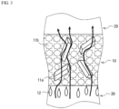
- the lower limit of a ratio of an average grain size of the reduced iron molded product to an average grain size of the iron ore material 11b excluding the aggregate 11a is preferably 1.3 and more preferably 1.4. As illustrated in FIG. 3 , even when a part of the iron ore material 11b excluding the aggregate 11a in the first layer 10 is melted and moves as a dripping slag 12 to the lower side of the blast furnace 1 and the iron ore material 11b excluding the aggregate 11a is softened and shrunk, the reduced iron molded product having a high melting point is not softened.
- the aggregate effect of the reduced iron molded product can be easily exerted, and layer shrinkage of the entire first layer 10 can be inhibited. Accordingly, by setting the ratio of the average grain sizes to be greater than or equal to the lower limit, a channel of the hot air shown by an arrow in FIG. 3 can be ensured, whereby the gas permeability in the reducing and melting step S2 can be improved.
- the upper limit of the ratio of the average grain sizes is preferably 10 and more preferably 5.
- the "average grain size” means a grain size at which a cumulative mass in a grain size distribution is 50%.
- the upper limit of a gas permeability resistance index after a tumbler rotation test of the reduced iron molded product is preferably 0.1 and more preferably 0.08.
- the reduced iron molded product is produced and used in different plants and subjected to transportation. During the transportation, volume breakage may occur, resulting in a change in the grain size distribution; therefore, by using the reduced iron molded product, which ensures that the gas permeability resistance index is less than or equal to a certain value even after the tumbler rotation test, the gas permeability in a lumpy zone E described later can be improved in actual blast furnace operation.
- the lower limit of the gas permeability resistance index is not particularly limited and may be a value close to 0, which is a theoretical limit value, but is typically approximately 0.03. It is to be noted that it is only required to use the reduced iron molded product having the gas permeability resistance index less than or equal to a predetermined value as a characteristic, and this does not mean that the tumbler rotation test is required in the method for producing pig iron.
- the "gas permeability resistance index after a tumbler rotation test" of the reduced iron molded product is calculated as follows. First, the tumbler rotation test is carried out pursuant to Determination of Tumble Strength of Iron Ores (JIS-M8712:2000) to obtain a grain size distribution of the reduced iron molded product through sieving. The grain size distribution is indicated with d i [cm] being a typical grain size (median) of mesh opening used for the sieving, and w i being a weight fraction of the reduced iron molded product belonging to the typical grain size d i . By using this grain size distribution, a harmonic mean diameter D p [cm] and a granularity composition index I sp are calculated according to the following formula 3.
- a gas permeability resistance index K is determined according to the following formula 3. It is to be noted that rotation conditions of the tumbler in the tumbler rotation test are 24 ⁇ 1 rpm and 600 times.
- the lower limit of a basicity of the reduced iron molded product is preferably 0.9 and more preferably 1.0.
- the contraction starting temperature of the reduced iron molded product is increased, whereby a contraction amount of the first layer 10 is reduced.
- the upper limit of the basicity of the reduced iron molded product is preferably 1.4 and more preferably 1.3.
- the strength of the reduced iron molded product may decrease. It is to be noted that the basicity of the reduced iron molded product can be adjusted by adding an auxiliary material such as limestone or the like at the time of producing the reduced iron molded product.
- the upper limit of a content of the aluminum oxide in the reduced iron molded product is preferably 1.5% by mass and more preferably 1.3% by mass.
- the content of the aluminum oxide is greater than the upper limit, an increase in slag melting point and/or an increase in viscosity may make it difficult to ensure the gas permeability in the lower furnace. Therefore, by setting the content of the aluminum oxide in the reduced iron molded product to be less than or equal to the upper limit, an increase in the amount of the coke 21 used can be inhibited.
- the content of the aluminum oxide may be 0% by mass, i.e., the reduced iron molded product may be the one not containing aluminum oxide; however, the lower limit of the content of the aluminum oxide is preferably 0.5% by mass.
- the content of the aluminum oxide is less than the lower limit, the reduced iron molded product may become expensive, leading to an increase in the production cost of the pig iron.
- the iron ore material 11 preferably include self-fluxing pellets.
- the self-fluxing pellets are superior in reducibility, and owing to the self-fluxing pellets thus included in the iron ore material 11, the reduction of the iron ore material 11 can be accelerated.
- the self-fluxing pellets preferably contain MgO.
- the MgO improves desulfurization ability of the slag at a hearth level and acts to improve the reducibility at high temperatures. Therefore, it is considered that by making the meltdown behavior of the self-fluxing pellets close to that of the reduced iron molded product, an action of accelerating the meltdown of the reduced iron molded product can be obtained.
- the lower limit of a MgO content in the self-fluxing pellets is preferably 1% by mass and more preferably 1.5% by mass.
- the upper limit of the MgO content in the self-fluxing pellets is preferably 4% by mass and more preferably 3% by mass.
- the MgO content in the self-fluxing pellets is less than the lower limit, the action of accelerating the meltdown of the reduced iron molded product may not be sufficiently obtained. Conversely, when the MgO content in the self-fluxing pellets is greater than the upper limit, the strength of the self-fluxing pellets may decrease.
- the lower limit of a basicity of the self-fluxing pellets is preferably 1.0, which indicates that they are a basic material, and more preferably 1.4. When the basicity of the self-fluxing pellets is less than the lower limit, it may be difficult to accelerate the meltdown of the reduced iron molded product, and the gas permeability may decrease.
- the upper limit of the basicity of the self-fluxing pellets is not particularly limited, and an average basicity of the self-fluxing pellets is typically less than or equal to 2.0.
- the self-fluxing pellets preferably have a MgO content of greater than or equal to 1.0% by mass and a basicity of greater than or equal to 1.0.
- auxiliary materials such as limestone, dolomite, and silica may also be charged in the first layer 10.
- the second layer 20 contains the coke 21.
- the coke 21 serves as: a heat source for melting the iron ore material 11; a reducing agent for generating CO gas necessary for the reduction of the iron ore material 11; a recarburizing agent for carburizing molten iron to lower the melting point; and a spacer for ensuring the gas permeability in the blast furnace 1.
- the lower limit of a coke ratio is preferably 200 kg/tp and more preferably 230 kg/tp.
- the upper limit of the coke ratio is preferably 290 kg/tp and more preferably 250 kg/tp.
- the "coke ratio” means a total mass [kg] of coke used as a reducing agent at the time of producing 1 ton of pig iron, and the coke encompasses coke charged in a portion other than the second layer 20.
- Various methods can be used as a method for alternately charging the first layer 10 and the second layer 20.
- the method is described herein with reference to, as an example, the blast furnace 1 equipped with the raw material charging device 2 of the bell-armor type (hereinafter, may be simply referred to as "raw material charging device 2") illustrated in FIG. 2 .
- the raw material charging device 2 is provided in a furnace top portion. In other words, the first layer 10 and the second layer 20 are charged from the furnace top. As illustrated in FIG. 2 , the raw material charging device 2 includes a bell cup 2a, a lower bell 2b, and an armor 2c.
- Raw materials to be charged are loaded into the bell cup 2a.
- a raw material constituting the first layer 10 is loaded into the bell cup 2a, and at the time of charging the second layer 20, a raw material constituting the second layer 20 is loaded.
- the lower bell 2b is in a cone shape expanding downward and is provided inside the bell cup 2a.
- the lower bell 2b is vertically movable ( FIG. 2 shows an upward moved state with a solid line, and a downward moved state with a dashed line).
- the lower bell 2b is configured to seal a lower portion of the bell cup 2a when moved upward, and to form a gap on an extended line of a sidewall of the bell cup 2a when moved downward.
- the armor 2c is provided below the lower bell 2b and on a furnace wall portion of the blast furnace 1. When the lower bell 2b is moved downward, the raw material falls through the gap, and the armor 2c serves as a rebound plate for rebounding the falling raw material. Furthermore, the armor 2c is configured to be protrudable and retractable with respect to the inside (central portion) of the blast furnace 1.
- the first layer 10 can be charged as follows. It is to be noted that the same applies to the second layer 20. Furthermore, the first layer 10 and the second layer 20 are alternately charged.
- the lower bell 2b is positioned on the upper side, and the raw material of the first layer 10 is charged in the bell cup 2a.
- the lower portion of the bell cup 2a is sealed; therefore, the raw material is loaded into the bell cup 2a.
- the loading amount is an amount of each layer to be charged.
- the lower bell 2b is moved downward. As a result, a gap is formed between the bell cup 2a and the lower bell 2b, and the raw material falls through the gap in the direction of the furnace wall to hit the armor 2c. After hitting and being rebounded by the armor 2c, the raw material is charged into the blast furnace 1. The raw material falls while moving in the inner furnace direction due to the rebound at the armor 2c, and is thus accumulated while flowing from the falling position toward the center of the blast furnace 1. Since the armor 2c is configured to be protrudable and retractable with respect to the central portion, the falling position of the raw material can be adjusted by protruding and retracting the armor 2c. This adjustment enables the first layer 10 to be accumulated in a desired shape.
- the iron ore material 11 in the first layer 10 charged is reduced and melted, while injecting the auxiliary reductant into the blast furnace 1 by the hot air blown from the tuyere 1a.
- the blast furnace operation is continuous, and thus, the reducing and melting step S2 is continuously performed.
- the charging step S1 is intermittently performed, and in accordance with the circumstances of the reducing and melting process of the first layer 10 and the second layer 20 in the reducing and melting step S2, the first layer 10 and the second layer 20 to be additionally processed in the reducing and melting step S2 are added.
- FIG. 2 illustrates a state in the reducing and melting step S2.
- a raceway A being a hollow portion in which the coke 21 whirls and is present in an extremely sparse state is formed in the vicinity of the tuyere 1a due to the hot air from the tuyere 1a.
- the temperature in the raceway A is the highest and is approximately 2,000 °C.
- FIG. 4 illustrates a state in the vicinity of the tuyere 1a and the raceway A of the blast furnace 1 in the reducing and melting step S2.
- the blast furnace 1 is provided with a tubular auxiliary reductant injection opening 1c connected to the tuyere 1a, and an auxiliary reductant 40 is injected from the auxiliary reductant injection opening 1c into the tuyere 1a.
- the auxiliary reductant injection opening 1c is installed with an outlet thereof directed to a downstream side of hot air H such that the auxiliary reductant 40 is carried by an airflow of the hot air H blown from the tuyere 1a, whereby pulverized coal 41 is injected deep into the raceway A.
- the auxiliary reductant 40 contains the pulverized coal 41.
- the auxiliary reductant 40 may contain, in addition to the pulverized coal 41, heavy oil, natural gas, and/or the like.
- the auxiliary reductant 40 functions as a heat source, a reducing agent, and a recarburizing agent. In other words, the auxiliary reductant 40 covers functions of the coke 21 except for the function as a spacer.
- the pulverized coal 41 is pulverized to a grain size of less than or equal to 500 ⁇ m and preferably less than or equal to 100 ⁇ m.
- a specific surface area of the pulverized coal 41 can be increased to improve the combustion efficiency.
- the lower limit of a pulverized coal ratio is 130 kg/tp and more preferably 150 kg/tp.
- the upper limit of the pulverized coal ratio is preferably 250 kg/tp and more preferably 220 kg/tp.
- the pulverized coal ratio is less than the lower limit, it may be difficult to lower the coke ratio while maintaining the stability of the blast furnace operation, resulting in difficulty in lowering the reducing agent ratio.
- the pulverized coal ratio is greater than the upper limit, the pulverized coal 41 may be excess in amount, making it difficult to lower the reducing agent ratio.
- the auxiliary reductant 40 injected is principally blown onto the coke 21 positioned deep in the raceway A. Consequently, an acidic slag derived from ash of the pulverized coal 41 melted deep in the raceway A is increased, whereby a bird's nest slag J is formed as a slag layer in which a slag with increased viscosity and melting point is accumulated (held up).
- the gas permeability in the lower furnace is deteriorated in the vicinity of the raceway A of the blast furnace 1.
- the reduced iron molded product pulverized to a grain size of less than or equal to 500 ⁇ m, preferably less than or equal to 100 ⁇ m is added to the auxiliary reductant 40.
- the reduced iron molded product When the auxiliary reductant 40 containing the reduced iron molded product is injected from the tuyere 1a, the reduced iron molded product is heated and melted in the raceway A, is integrated and slagged with the bird's nest slag J previously formed, and rapidly drips as the dripping slag 12. As a result, the growth of the bird's nest slag J is inhibited, whereby the gas permeability can be maintained. When the gas permeability is maintained, the hot air H can be easily permeated to the central portion of the blast furnace 1, resulting in a reduction in the amount of the coke 21 used.
- the lower limit of an injection amount of the reduced iron molded product is preferably 3 kg and more preferably 5 kg per ton of pig iron. When the injection amount is less than the lower limit, the effect of improving the gas permeability may be insufficient.
- the upper limit of a reducing agent ratio of the reducing agent containing the coke 21 and the pulverized coal 41 of the second layer 20 is 440 kg/tp and more preferably 430 kg/tp.
- the reduced iron molded product (aggregate 11a) contained in the iron ore material 11 of the first layer 10 enables the gas permeability in the blast furnace 1 to be ensured, and thus, stable blast furnace operation can be maintained at a reducing agent ratio that is less than or equal to the upper limit. Accordingly, CO 2 emissions can be sufficiently reduced.
- the lower limit of the reducing agent ratio is preferably 400 kg/tp and more preferably 410 kg/tp.
- the amount of the coke 21 charged in the second layer 20 may be limited, making it difficult to ensure the gas permeability in the blast furnace 1, and/or the amount of the pulverized coal 41 in the auxiliary reductant 40 may be limited, making it difficult to maintain the stability of the blast furnace operation.
- the hot air H (air and added oxygen) blown from the tuyere 1a, moisture contained in the hot air H, and the auxiliary reductant 40 containing the pulverized coal 41 are gasified (into bosh gas) in the tuyere 1a.
- the lower limit of a bosh gas rate is preferably 1,290 Nm 3 /tp and more preferably 1,310 Nm 3 /tp.
- the upper limit of a bosh gas rate is preferably 1,350 Nm 3 /tp and more preferably 1,330 Nm 3 /tp.
- the melting capacity of the lower furnace tends to be proportional to the bosh gas sensible heat and accordingly the bosh gas rate.
- the oxygen enrichment enables increasing the bosh gas sensible heat by an increase in a temperature in front of the tuyere; however, even in a case in which the temperature in front of the tuyere is lowered by the nitrogen enrichment, the melting capacity can be enhanced by an increase in the bosh gas rate. Therefore, by controlling the bosh gas rate, the controllability of melting of the reduced iron in the lower furnace can be improved, and thus, the operational stability of the blast furnace 1 can be further improved.
- the "bosh gas rate" means a value obtained by dividing the total amount of the bosh gas per unit time by the output amount of pig iron per unit time.
- the upper limit of a lower furnace heat ratio is preferably 0.5 and more preferably 0.45.
- the lower furnace heat ratio can be adjusted by controlling the bosh gas sensible heat.
- the lower limit of the lower furnace heat ratio is determined, in a case in which the bosh gas is excess in amount, by a flooding limit, at which the operation becomes unstable owing to dripping molten iron and a slag blown up by the bosh gas, and/or a combustion temperature limit, at which plasma is generated at approximately 3,500 °C and the temperature does not rise any more, and is, for example, 0.2.
- the "lower furnace heat ratio" can be calculated according to the following formula 4 from the sensible heats of the molten iron, the slag, and the bosh gas. It is to be noted that each sensible heat in the following formula 4 is calculated under the following conditions.
- a molten iron specific heat is 0.75 kJ/kg/K
- a slag specific heat is 1.26 kJ/kg/K
- a specific heat of N 2 is 1.30 kJ/Nm 3 /K
- that of CO is 1.31 kJ/Nm 3 /K
- that of H 2 is 1.28 kJ/Nm 3 /K.
- Lower furnace heat ratio ⁇ (molten iron sensible heat) + (slag sensible heat) ⁇ / (bosh gas sensible heat) 4
- the lower limit of the temperature of the hot air H in front of the tuyere is preferably 2,100 °C and more preferably 2,120 °C.
- the upper limit of the temperature in front of the tuyere is preferably 2,200 °C and more preferably 2,170 °C.
- the lower furnace melting capacity may become too high, fixation due to evaporation and resolidification of the slag may occur with an increase in the pressure loss in the lower furnace due to rapid melting of the reduced iron, and a decent failure or the like such as hanging may occur, leading to unstable blast furnace operation.
- the upper limit of an oxygen enrichment rate of the hot air H is preferably 2.5% by volume and more preferably 2% by volume.
- operation at a constant output amount of pig iron is preferred.
- the output amount of pig iron decreases with a decrease of oxygen in the hot air H.
- oxygen in the hot air H is constant, the output amount of pig iron increases with a decrease in the reducing agent ratio. Since the method for producing pig iron is oriented to operation at a low reducing agent ratio, the oxygen amount needs to be reduced to keep a constant output amount of pig iron.
- the lower limit of the nitrogen enrichment rate of the hot air H is preferably 0% by volume.
- the oxygen enrichment rate is less than or equal to 0% by volume.
- the upper limit of the nitrogen enrichment rate of the hot air H is, due to restrictions such as an increase in the pressure loss accompanying an increase in the bosh gas amount and the flooding limit, preferably 4% by volume and, in light of the melting capacity, more preferably 2% by volume.
- the bosh gas sensible heat which is a source of the melting capacity, is proportional to a product of the temperature of the hot air H in front of the tuyere and the bosh gas rate. Furthermore, the bosh gas is composed of: carbon monoxide gas obtained by partial oxidation of the coke and/or the pulverized coal by oxygen supplied to the tuyere; and hydrogen and nitrogen generated by a thermal decomposition reaction of the pulverized coal and the like, and net reaction heat (difference between the heat generated by the partial oxidation and the heat absorbed in the thermal decomposition reaction) in a combustion field (raceway space) is constant when the oxygen amount is constant.
- enriched oxygen and enriched nitrogen are heated in an air-heating furnace together with the air from a blower and then supplied to the tuyere.
- oxygen enrichment When the oxygen enrichment is high, sensible heat supplied to the combustion field decreases with a decrease of nitrogen in the air. Conversely, when the nitrogen enrichment is high, the sensible heat supplied to the combustion field increases.
- the nitrogen enrichment leads to a low temperature in front of the tuyere but high bosh gas sensible heat. That is to say, the melting capacity can be controlled by the oxygen enrichment and the nitrogen enrichment.
- a deadman B which is a pseudo-stagnation zone of the coke inside the blast furnace 1, is present adjacent to the raceway A. Furthermore, above the deadman B, a dripping zone C, a cohesive zone D, and a lumpy zone E are present in this order.
- the temperature in the blast furnace 1 increases from the top toward the raceway A.
- the temperature increases in the order of the lumpy zone E, the cohesive zone D, and the dripping zone C; for example, the temperature in the lumpy zone E is approximately 20 °C to 1,200 °C, while the temperature in the deadman B is approximately 1,200 °C to 1,600 °C.
- the temperature in the deadman B varies in a radial direction, and the temperature in a central portion of the deadman B may be lower than the temperature in the dripping zone C.
- the cohesive zone D having an inverted V-shaped cross section is formed, whereby the gas permeability and reducibility in the blast furnace 1 are ensured.
- the iron ore material 11 is first heated and reduced in the lumpy zone E.
- the cohesive zone D the iron ore reduced in the lumpy zone E is softened and shrunk.
- the softened and shrunk iron ore descends as the dripping slag and moves to the dripping zone C.
- the reduction of the iron ore material 11 proceeds principally in the lumpy zone E, and the melting of the iron ore material 11 occurs principally in the dripping zone C. It is to be noted that in the dripping zone C and the deadman B, direct reduction proceeds, which is a direct reaction between descending liquid iron oxide FeO and carbon in the coke 21.
- the aggregate 11a containing the reduced iron molded product exerts the aggregate effect in the cohesive zone D.
- the reduced iron molded product having a high melting point is not softened, and thus, a gas permeation channel for surely permeating the hot air to the central portion of the blast furnace 1 is ensured.
- the molten iron F obtained by melting the reduced iron is accumulated on a hearth portion, and a molten slag G is accumulated on the molten iron F.
- the molten iron F and the molten slag G can be tapped from the taphole 1b.
- the reduced iron molded product obtained by compression molding of the reduced iron acts as the aggregate 11a, and its total amount in terms of the blending amount of the reduced iron is greater than or equal to 200 kg per ton of pig iron; therefore, the hot air H can be easily permeated at the time of softening and fusing the first layer 10 in the reducing and melting step S2, and thus, the amount of the coke 21 for ensuring the gas permeability can be reduced.
- stable operation of the blast furnace 1 can be enhanced by using, as the auxiliary reductant 40, the pulverized coal 41 at a pulverized coal ratio of greater than or equal to 130 kg/tp. Accordingly, by using the method for producing pig iron, stable operation of the blast furnace 1 can be maintained even at a low reducing agent ratio of less than or equal to 440 kg/tp.
- the method for producing pig iron of the present invention includes only the charging step and the reducing and melting step has been described; however, the method for producing pig iron may include other step(s).
- the method for producing pig iron may further include a step of charging, in the central portion of the blast furnace, a mixture of coke and a reduced iron molded product.
- a proportion accounted for by a reduced iron molded product having a grain size of greater than or equal to 5 mm is greater than or equal to 90% by mass, and that a content of the reduced iron molded product in the mixture is less than or equal to 75% by mass.
- the "central portion" of the blast furnace means a region at a distance of less than or equal to 0.2 Z from the central axis of the blast furnace, wherein Z denotes a radius of a furnace throat portion.
- bell-armor type used in the charging step of the above embodiment
- a different type may also be used.
- Example of such a different type include a bell-less type. With the bell-less type, charging can be performed using a swivel chute while adjusting its angle.
- the above results indicate that by setting the blending amount of the reduced iron to greater than or equal to 200 kg per ton of pig iron to be produced, setting the pulverized coal ratio to greater than or equal to 130 kg/tp, and setting the reducing agent ratio to less than or equal to 440 kg/tp, the reducing agent ratio can be reduced while maintaining stable operation of the blast furnace.
- the method for producing pig iron of the present invention enables a reduction in the reducing agent ratio while maintaining stable operation of the blast furnace.
Landscapes
- Engineering & Computer Science (AREA)
- Chemical & Material Sciences (AREA)
- Manufacturing & Machinery (AREA)
- Materials Engineering (AREA)
- Metallurgy (AREA)
- Organic Chemistry (AREA)
- Life Sciences & Earth Sciences (AREA)
- Environmental & Geological Engineering (AREA)
- General Life Sciences & Earth Sciences (AREA)
- Geochemistry & Mineralogy (AREA)
- Geology (AREA)
- Mechanical Engineering (AREA)
- Manufacture Of Iron (AREA)
Abstract
Description
- The present invention relates to a method for producing pig iron.
- Known is a method for producing pig iron by: charging a first layer containing an iron ore material and a second layer containing coke alternately in a blast furnace; and reducing and melting the iron ore material, while injecting an auxiliary reductant into the blast furnace by hot air blown from a tuyere. At this time, the coke serves as: a heat source for melting the iron ore material; a reducing agent for the iron ore material; a recarburizing agent for carburizing molten iron to lower the melting point; and a spacer for ensuring gas permeability in the blast furnace. Due to the coke maintaining the gas permeability, descent of the burden charged as the first layer and the second layer is stabilized, and in turn, stable operation of the blast furnace is enabled.
- With a growing awareness of recent environmental problems, it is required to reduce emissions of CO2, which is a greenhouse gas, also in blast furnace operation. As a method for reducing CO2 emissions, a method for producing pig iron has been proposed, in which the productivity is improved by increasing the output ratio and the amount of coke used is reduced (see
Japanese Unexamined Patent Application, Publication No. 2014-132108 - According to the method for producing pig iron disclosed in this document, the amount of coke used can be reduced by increasing the injection amount of pulverized coal, which is the auxiliary reductant in the hot air blown from the tuyere, and the oxygen enrichment rate in oxygen-enriched air, leading to a reduction in greenhouse gas emissions.
- Patent Document 1:
Japanese Unexamined Patent Application, Publication No. 2014-132108 - In the conventional method for producing pig iron, although the reduction in the amount of coke used is achieved, the injection amount of the pulverized coal is increased. Since the pulverized coal is also a source of CO2 emissions, it cannot be said that the CO2 emissions are sufficiently reduced as a whole.
- The present invention has been made in view of the foregoing circumstances, and an object of the present invention is to provide a method for producing pig iron which enables a reduction in a reducing agent ratio while maintaining stable operation of a blast furnace.
- An aspect of the present invention is a method for producing pig iron using a blast furnace including a tuyere, the method including: charging a first layer containing an iron ore material and a second layer containing coke alternately in the blast furnace; and reducing and melting the iron ore material in the first layer charged, while injecting an auxiliary reductant into the blast furnace by hot air blown from the tuyere, wherein: the iron ore material contains a reduced iron molded product obtained by compression molding of reduced iron, the auxiliary reductant contains pulverized coal, a blending amount of the reduced iron is greater than or equal to 200 kg per ton of pig iron to be produced, and a reducing agent ratio of a reducing agent containing the coke and the pulverized coal is less than or equal to 440 kg/tp, and a pulverized coal ratio is greater than or equal to 130 kg/tp.
- In the method for producing pig iron, the reduced iron molded product obtained by compression molding of the reduced iron acts as an aggregate, and its total amount in terms of the blending amount of the reduced iron is greater than or equal to the lower limit; therefore, the hot air can be easily permeated at a time of softening and fusing the first layer in the reducing and melting step, and thus, the amount of coke for ensuring the gas permeability can be reduced. Moreover, in the method for producing pig iron, stable operation of the blast furnace can be enhanced by using, as the auxiliary reductant, the pulverized coal at a pulverized coal ratio that is greater than or equal to the lower limit. Accordingly, by using the method for producing pig iron, stable operation of the blast furnace can be maintained even at a low reducing agent ratio that is less than or equal to the upper limit.
- It is preferred that the iron ore material includes self-fluxing pellets containing MgO, and that the self-fluxing pellets have a MgO content of greater than or equal to 1.0% by mass and a basicity of greater than or equal to 1.0. The self-fluxing pellets are superior in reducibility, and owing to the self-fluxing pellets, which have a MgO content of greater than or equal to 1.0% by mass and a basicity of greater than or equal to 1.0, included in the iron ore material, reduction of the iron ore material and meltdown of the reduced iron molded product can be accelerated.
- A lower furnace heat ratio is preferably less than or equal to 0.5. By thus setting the lower furnace heat ratio to be less than or equal to the upper limit, the melting capacity of the lower furnace can be improved, and the operational stability of the blast furnace can be further improved.
- An oxygen enrichment rate of the hot air is preferably less than or equal to 2.5% by volume. By thus setting the oxygen enrichment rate of the hot air to be less than or equal to the upper limit, the operational stability of the blast furnace can be improved while maintaining a low reducing agent ratio.
- A nitrogen enrichment rate of the hot air is preferably greater than or equal to 0% by volume. By thus setting the nitrogen enrichment rate of the hot air to be greater than or equal to the lower limit, bosh gas sensible heat can be increased, and thus, the melting capacity can be improved.
- As referred to herein, the "pulverized coal" means coal pulverized to a grain size of approximately 50 µm, and the "pulverized coal ratio" means a mass [kg] of pulverized coal injected from the tuyere at the time of producing 1 ton of pig iron. The "reducing agent ratio" means a total mass [kg] of the reducing agent necessary for the production of 1 ton of pig iron, and the reducing agent encompasses all substances that reduce the iron ore material, such as coke, pulverized coal, and heavy oil.
- The "basicity" means a proportion of a mass of CaO with respect to a mass of SiO2. It is to be noted that in a case in which a target substance is composed of a plurality of granular substances, the basicity means a proportion of a total mass of CaO with respect to a total mass of SiO2 in the plurality of granular substances.
- The "lower furnace heat ratio" means a value obtained by dividing a sum of sensible heat of molten iron and slag sensible heat by the bosh gas sensible heat. It is to be noted that the "bosh gas" means a gas at a moment at which the hot air blown from the tuyere, added oxygen, moisture in the hot air, and the auxiliary reductant containing the pulverized coal are gasified in the tuyere.
- To control the combustion temperature, oxygen and/or nitrogen may be added to the hot air. When oxygen is added, the oxygen concentration in the hot air becomes higher than that in the air (21% by volume); when nitrogen is added, the oxygen concentration in the hot air becomes lower than that in the air (21% by volume). The addition of oxygen is referred to as oxygen enrichment, and the addition of nitrogen is referred to as nitrogen enrichment. As referred to herein, the "oxygen enrichment rate" of the hot air means, assuming that the air is defined as the hot air including oxygen blown from the tuyere, a proportion of enriched oxygen with respect to the oxygen amount in the air (21% by volume), and an oxygen enrichment rate RO2 is calculated according to the following
formula 1. For example, an oxygen enrichment rate of 2.5% by volume means that oxygen accounts for 21 + 2.5 = 23.5% by volume of the hot air amount (air amount + oxygen amount + nitrogen amount). It is to be noted that in the case of the nitrogen enrichment, the solution of the followingformula 1 is a negative value.RO2 = {(air amount × 0.21 + oxygen amount) - hot air amount × 0.21} / hot air amount × 100 1 - Similarly, the "nitrogen enrichment rate" of the hot air means, assuming that the air is defined as the hot air including nitrogen blown from the tuyere, a proportion of enriched nitrogen with respect to nitrogen in the air (79% by volume), and a nitrogen enrichment rate RN2 is calculated according to the following
formula 2. For example, a nitrogen enrichment rate of 2.5% by volume means that nitrogen accounts for 79 + 2.5 = 81.5% by volume of the hot air amount (air amount + oxygen amount + nitrogen amount). It is to be noted that in the case of the oxygen enrichment, the solution of the followingformula 2 is a negative value.RN2 = {(air amount × 0.79 + nitrogen amount) - hot air amount × 0.79} / hot air amount × 100 2 - As described above, the method for producing pig iron of the present invention enables a reduction in the reducing agent ratio while maintaining stable operation of the blast furnace.
-
-
FIG. 1 is a flowchart illustrating a method for producing pig iron according to one embodiment of the present invention. -
FIG. 2 is a schematic view illustrating the inside of a blast furnace used in the method for producing pig iron inFIG. 1 . -
FIG. 3 is a schematic partial enlarged view of the vicinity of an area from a cohesive zone to a dripping zone inFIG. 2 . -
FIG. 4 is a view schematically illustrating a process conducted at a tuyere in the reducing and melting step inFIG. 1 . - Hereinafter, a method for producing pig iron according to each embodiment of the present invention will be described.
- The method for producing pig iron illustrated in
FIG. 1 is a method for producing pig iron by using ablast furnace 1 illustrated inFIG. 2 and includes a charging step S1 and a reducing and melting step S2. - As illustrated in
FIG. 2 , theblast furnace 1 includes atuyere 1a and ataphole 1b provided in a lower furnace. Typically, a plurality oftuyeres 1a are provided. Theblast furnace 1 is a solid-gas countercurrent type shaft furnace and can operate in such a manner that hot air obtained by adding, as necessary, high-temperature or normal-temperature oxygen to high-temperature air is blown from thetuyere 1a into theblast furnace 1, a series of reactions such as reduction and melting of aniron ore material 11 described later is conducted, and then pig iron is tapped from thetaphole 1b. Furthermore, theblast furnace 1 is equipped with a rawmaterial charging device 2 of the bell-armor type. The rawmaterial charging device 2 will be described later. - The lower limit of a furnace volume of the
blast furnace 1, which means a volume from a furnace bottom to a specified raw material charging line, is preferably 2,000 m3 and more preferably 4,000 m3. The method for producing pig iron can be particularly suitably used in the operation of a blast furnace having a furnace volume that is greater than or equal to the lower limit. The upper limit of the furnace volume of theblast furnace 1 for which the method for producing pig iron can be suitably used is not particularly limited, and the method for producing pig iron functions more suitably as the furnace volume increases; the practical upper limit of the furnace volume of theblast furnace 1 is approximately 7,000 m3. - In the charging step S1, a
first layer 10 and asecond layer 20 are alternately charged in theblast furnace 1 as illustrated inFIG. 2 . In other words, the numbers offirst layers 10 andsecond layers 20 are each greater than or equal to 2. - The
first layer 10 contains theiron ore material 11. In the reducing and melting step S2, theiron ore material 11 is heated and reduced into molten iron F by the hot air blown from thetuyere 1a. - The
iron ore material 11 refers to mineral ore serving as an iron raw material and principally contains iron ore. Examples of theiron ore material 11 include calcined iron ore (iron ore pellet, sintered iron ore), lump iron ore, carbon composite agglomerated iron ore, metal, and the like. Furthermore, theiron ore material 11 contains an aggregate 11a. - The aggregate 11a serves to improve the gas permeability in a cohesive zone D described later, whereby the hot air is permeated to a central portion of the
blast furnace 1. The aggregate 11a contains a reduced iron molded product (hot briquette iron: HBI) obtained by compression molding of reduced iron. In other words, theiron ore material 11 contains the reduced iron molded product. - The HBI is obtained by molding direct reduced iron (DRI) in a hot state. The DRI is high in porosity and has a drawback in that oxidation and heat generation occur during marine transportation and/or outdoor storage, while the HBI is low in porosity and less likely to be re-oxidized. After serving to ensure the gas permeability of the
first layer 10, the aggregate 11a functions as a metal and becomes molten iron. The aggregate 11a is high in metallization rate and requires no reduction, and thus does not require a large amount of a reducing agent at the time of becoming the molten iron. Accordingly, CO2 emissions can be reduced. It is to be noted that the "metallization rate" means a proportion [% by mass] of metallic iron with respect to the total iron content. - The lower limit of a blending amount of the reduced iron (total blending amount of reduced iron constituting the reduced iron molded product) is 200 kg, more preferably 250 kg, and still more preferably 300 kg per ton of pig iron to be produced. When the blending amount of the reduced iron is less than the lower limit, the reducing agent ratio may not be sufficiently reduced. On the other hand, the upper limit of the blending amount of the reduced iron is appropriately determined in a range in which an aggregate effect is not diminished owing to excessive aggregate, and the upper limit of the blending amount of the reduced iron is, for example, 700 kg per ton of pig iron to be produced.
- The lower limit of a ratio of an average grain size of the reduced iron molded product to an average grain size of the
iron ore material 11b excluding the aggregate 11a is preferably 1.3 and more preferably 1.4. As illustrated inFIG. 3 , even when a part of theiron ore material 11b excluding the aggregate 11a in thefirst layer 10 is melted and moves as a drippingslag 12 to the lower side of theblast furnace 1 and theiron ore material 11b excluding the aggregate 11a is softened and shrunk, the reduced iron molded product having a high melting point is not softened. When the reduced iron molded product having a size greater than that of theiron ore material 11b excluding the aggregate 11a to a certain degree is mixed as the aggregate 11a, the aggregate effect of the reduced iron molded product can be easily exerted, and layer shrinkage of the entirefirst layer 10 can be inhibited. Accordingly, by setting the ratio of the average grain sizes to be greater than or equal to the lower limit, a channel of the hot air shown by an arrow inFIG. 3 can be ensured, whereby the gas permeability in the reducing and melting step S2 can be improved. On the other hand, the upper limit of the ratio of the average grain sizes is preferably 10 and more preferably 5. When the ratio of the average grain sizes is greater than the upper limit, it may be difficult to uniformly mix the reduced iron molded product in thefirst layer 10, leading to an increase in segregation. It is to be noted that the "average grain size" means a grain size at which a cumulative mass in a grain size distribution is 50%. - The upper limit of a gas permeability resistance index after a tumbler rotation test of the reduced iron molded product is preferably 0.1 and more preferably 0.08. Typically, the reduced iron molded product is produced and used in different plants and subjected to transportation. During the transportation, volume breakage may occur, resulting in a change in the grain size distribution; therefore, by using the reduced iron molded product, which ensures that the gas permeability resistance index is less than or equal to a certain value even after the tumbler rotation test, the gas permeability in a lumpy zone E described later can be improved in actual blast furnace operation. On the other hand, the lower limit of the gas permeability resistance index is not particularly limited and may be a value close to 0, which is a theoretical limit value, but is typically approximately 0.03. It is to be noted that it is only required to use the reduced iron molded product having the gas permeability resistance index less than or equal to a predetermined value as a characteristic, and this does not mean that the tumbler rotation test is required in the method for producing pig iron.
- As referred to herein, the "gas permeability resistance index after a tumbler rotation test" of the reduced iron molded product is calculated as follows. First, the tumbler rotation test is carried out pursuant to Determination of Tumble Strength of Iron Ores (JIS-M8712:2000) to obtain a grain size distribution of the reduced iron molded product through sieving. The grain size distribution is indicated with di [cm] being a typical grain size (median) of mesh opening used for the sieving, and wi being a weight fraction of the reduced iron molded product belonging to the typical grain size di. By using this grain size distribution, a harmonic mean diameter Dp [cm] and a granularity composition index Isp are calculated according to the following formula 3. Furthermore, by using a gravitational conversion factor gc [9.807 (g·cm)/(G·sec2)], a gas permeability resistance index K is determined according to the following formula 3. It is to be noted that rotation conditions of the tumbler in the tumbler rotation test are 24±1 rpm and 600 times.



- The lower limit of a basicity of the reduced iron molded product is preferably 0.9 and more preferably 1.0. By thus setting the basicity of the reduced iron molded product to be greater than or equal to the lower limit, the contraction starting temperature of the reduced iron molded product is increased, whereby a contraction amount of the
first layer 10 is reduced. This improves the gas permeability in the cohesive zone D in the reducing and melting step S2 and enables the hot air to be surely permeated to the central portion of theblast furnace 1. Accordingly, the amount of thecoke 21 used can be reduced. On the other hand, the upper limit of the basicity of the reduced iron molded product is preferably 1.4 and more preferably 1.3. When the basicity of the reduced iron molded product is greater than the upper limit, the strength of the reduced iron molded product may decrease. It is to be noted that the basicity of the reduced iron molded product can be adjusted by adding an auxiliary material such as limestone or the like at the time of producing the reduced iron molded product. - Furthermore, in a case in which the reduced iron molded product contains aluminum oxide, the upper limit of a content of the aluminum oxide in the reduced iron molded product is preferably 1.5% by mass and more preferably 1.3% by mass. When the content of the aluminum oxide is greater than the upper limit, an increase in slag melting point and/or an increase in viscosity may make it difficult to ensure the gas permeability in the lower furnace. Therefore, by setting the content of the aluminum oxide in the reduced iron molded product to be less than or equal to the upper limit, an increase in the amount of the
coke 21 used can be inhibited. It is to be noted that the content of the aluminum oxide may be 0% by mass, i.e., the reduced iron molded product may be the one not containing aluminum oxide; however, the lower limit of the content of the aluminum oxide is preferably 0.5% by mass. When the content of the aluminum oxide is less than the lower limit, the reduced iron molded product may become expensive, leading to an increase in the production cost of the pig iron. - The
iron ore material 11 preferably include self-fluxing pellets. The self-fluxing pellets are superior in reducibility, and owing to the self-fluxing pellets thus included in theiron ore material 11, the reduction of theiron ore material 11 can be accelerated. - The self-fluxing pellets preferably contain MgO. The MgO improves desulfurization ability of the slag at a hearth level and acts to improve the reducibility at high temperatures. Therefore, it is considered that by making the meltdown behavior of the self-fluxing pellets close to that of the reduced iron molded product, an action of accelerating the meltdown of the reduced iron molded product can be obtained. The lower limit of a MgO content in the self-fluxing pellets is preferably 1% by mass and more preferably 1.5% by mass. On the other hand, the upper limit of the MgO content in the self-fluxing pellets is preferably 4% by mass and more preferably 3% by mass. When the MgO content in the self-fluxing pellets is less than the lower limit, the action of accelerating the meltdown of the reduced iron molded product may not be sufficiently obtained. Conversely, when the MgO content in the self-fluxing pellets is greater than the upper limit, the strength of the self-fluxing pellets may decrease.
- The lower limit of a basicity of the self-fluxing pellets is preferably 1.0, which indicates that they are a basic material, and more preferably 1.4. When the basicity of the self-fluxing pellets is less than the lower limit, it may be difficult to accelerate the meltdown of the reduced iron molded product, and the gas permeability may decrease. The upper limit of the basicity of the self-fluxing pellets is not particularly limited, and an average basicity of the self-fluxing pellets is typically less than or equal to 2.0.
- It is to be noted that in light of accelerating the meltdown of the reduced iron molded product, the self-fluxing pellets preferably have a MgO content of greater than or equal to 1.0% by mass and a basicity of greater than or equal to 1.0.
- In addition to the
iron ore material 11, auxiliary materials such as limestone, dolomite, and silica may also be charged in thefirst layer 10. - The
second layer 20 contains thecoke 21. - The
coke 21 serves as: a heat source for melting theiron ore material 11; a reducing agent for generating CO gas necessary for the reduction of theiron ore material 11; a recarburizing agent for carburizing molten iron to lower the melting point; and a spacer for ensuring the gas permeability in theblast furnace 1. - The lower limit of a coke ratio is preferably 200 kg/tp and more preferably 230 kg/tp. On the other hand, the upper limit of the coke ratio is preferably 290 kg/tp and more preferably 250 kg/tp. When the coke ratio is less than the lower limit, stable operation of the
blast furnace 1 may not be maintained. Conversely, when the coke ratio is greater than the upper limit, operation at a low reducing agent ratio may be difficult. The "coke ratio" means a total mass [kg] of coke used as a reducing agent at the time of producing 1 ton of pig iron, and the coke encompasses coke charged in a portion other than thesecond layer 20. - Various methods can be used as a method for alternately charging the
first layer 10 and thesecond layer 20. The method is described herein with reference to, as an example, theblast furnace 1 equipped with the rawmaterial charging device 2 of the bell-armor type (hereinafter, may be simply referred to as "rawmaterial charging device 2") illustrated inFIG. 2 . - The raw
material charging device 2 is provided in a furnace top portion. In other words, thefirst layer 10 and thesecond layer 20 are charged from the furnace top. As illustrated inFIG. 2 , the rawmaterial charging device 2 includes abell cup 2a, alower bell 2b, and anarmor 2c. - Raw materials to be charged are loaded into the
bell cup 2a. At the time of charging thefirst layer 10, a raw material constituting thefirst layer 10 is loaded into thebell cup 2a, and at the time of charging thesecond layer 20, a raw material constituting thesecond layer 20 is loaded. - The
lower bell 2b is in a cone shape expanding downward and is provided inside thebell cup 2a. Thelower bell 2b is vertically movable (FIG. 2 shows an upward moved state with a solid line, and a downward moved state with a dashed line). Thelower bell 2b is configured to seal a lower portion of thebell cup 2a when moved upward, and to form a gap on an extended line of a sidewall of thebell cup 2a when moved downward. - The
armor 2c is provided below thelower bell 2b and on a furnace wall portion of theblast furnace 1. When thelower bell 2b is moved downward, the raw material falls through the gap, and thearmor 2c serves as a rebound plate for rebounding the falling raw material. Furthermore, thearmor 2c is configured to be protrudable and retractable with respect to the inside (central portion) of theblast furnace 1. - By using the raw
material charging device 2, thefirst layer 10 can be charged as follows. It is to be noted that the same applies to thesecond layer 20. Furthermore, thefirst layer 10 and thesecond layer 20 are alternately charged. - First, the
lower bell 2b is positioned on the upper side, and the raw material of thefirst layer 10 is charged in thebell cup 2a. When thelower bell 2b is positioned on the upper side, the lower portion of thebell cup 2a is sealed; therefore, the raw material is loaded into thebell cup 2a. It is to be noted that the loading amount is an amount of each layer to be charged. - Next, the
lower bell 2b is moved downward. As a result, a gap is formed between thebell cup 2a and thelower bell 2b, and the raw material falls through the gap in the direction of the furnace wall to hit thearmor 2c. After hitting and being rebounded by thearmor 2c, the raw material is charged into theblast furnace 1. The raw material falls while moving in the inner furnace direction due to the rebound at thearmor 2c, and is thus accumulated while flowing from the falling position toward the center of theblast furnace 1. Since thearmor 2c is configured to be protrudable and retractable with respect to the central portion, the falling position of the raw material can be adjusted by protruding and retracting thearmor 2c. This adjustment enables thefirst layer 10 to be accumulated in a desired shape. - In the reducing and melting step S2, the
iron ore material 11 in thefirst layer 10 charged is reduced and melted, while injecting the auxiliary reductant into theblast furnace 1 by the hot air blown from thetuyere 1a. - It is to be noted that the blast furnace operation is continuous, and thus, the reducing and melting step S2 is continuously performed. On the other hand, the charging step S1 is intermittently performed, and in accordance with the circumstances of the reducing and melting process of the
first layer 10 and thesecond layer 20 in the reducing and melting step S2, thefirst layer 10 and thesecond layer 20 to be additionally processed in the reducing and melting step S2 are added. -
FIG. 2 illustrates a state in the reducing and melting step S2. As illustrated inFIG. 2 , a raceway A being a hollow portion in which thecoke 21 whirls and is present in an extremely sparse state is formed in the vicinity of thetuyere 1a due to the hot air from thetuyere 1a. In theblast furnace 1, the temperature in the raceway A is the highest and is approximately 2,000 °C. -
FIG. 4 illustrates a state in the vicinity of thetuyere 1a and the raceway A of theblast furnace 1 in the reducing and melting step S2. Theblast furnace 1 is provided with a tubular auxiliary reductant injection opening 1c connected to thetuyere 1a, and anauxiliary reductant 40 is injected from the auxiliary reductant injection opening 1c into thetuyere 1a. - The auxiliary reductant injection opening 1c is installed with an outlet thereof directed to a downstream side of hot air H such that the
auxiliary reductant 40 is carried by an airflow of the hot air H blown from thetuyere 1a, whereby pulverizedcoal 41 is injected deep into the raceway A. - The
auxiliary reductant 40 contains the pulverizedcoal 41. Theauxiliary reductant 40 may contain, in addition to the pulverizedcoal 41, heavy oil, natural gas, and/or the like. Theauxiliary reductant 40 functions as a heat source, a reducing agent, and a recarburizing agent. In other words, theauxiliary reductant 40 covers functions of thecoke 21 except for the function as a spacer. - It is preferred that the pulverized
coal 41 is pulverized to a grain size of less than or equal to 500 µm and preferably less than or equal to 100 µm. By setting the maximum grain size of the pulverizedcoal 41 to be less than or equal to the upper limit, a specific surface area of the pulverizedcoal 41 can be increased to improve the combustion efficiency. - The lower limit of a pulverized coal ratio is 130 kg/tp and more preferably 150 kg/tp. On the other hand, the upper limit of the pulverized coal ratio is preferably 250 kg/tp and more preferably 220 kg/tp. When the pulverized coal ratio is less than the lower limit, it may be difficult to lower the coke ratio while maintaining the stability of the blast furnace operation, resulting in difficulty in lowering the reducing agent ratio. Conversely, when the pulverized coal ratio is greater than the upper limit, the pulverized
coal 41 may be excess in amount, making it difficult to lower the reducing agent ratio. - The
auxiliary reductant 40 injected is principally blown onto thecoke 21 positioned deep in the raceway A. Consequently, an acidic slag derived from ash of the pulverizedcoal 41 melted deep in the raceway A is increased, whereby a bird's nest slag J is formed as a slag layer in which a slag with increased viscosity and melting point is accumulated (held up). - As the bird's nest slag J grows, the gas permeability in the lower furnace is deteriorated in the vicinity of the raceway A of the
blast furnace 1. To inhibit the deterioration of the gas permeability, it is preferred that the reduced iron molded product pulverized to a grain size of less than or equal to 500 µm, preferably less than or equal to 100 µm is added to theauxiliary reductant 40. - When the
auxiliary reductant 40 containing the reduced iron molded product is injected from thetuyere 1a, the reduced iron molded product is heated and melted in the raceway A, is integrated and slagged with the bird's nest slag J previously formed, and rapidly drips as the drippingslag 12. As a result, the growth of the bird's nest slag J is inhibited, whereby the gas permeability can be maintained. When the gas permeability is maintained, the hot air H can be easily permeated to the central portion of theblast furnace 1, resulting in a reduction in the amount of thecoke 21 used. - The lower limit of an injection amount of the reduced iron molded product is preferably 3 kg and more preferably 5 kg per ton of pig iron. When the injection amount is less than the lower limit, the effect of improving the gas permeability may be insufficient.
- The upper limit of a reducing agent ratio of the reducing agent containing the
coke 21 and the pulverizedcoal 41 of thesecond layer 20 is 440 kg/tp and more preferably 430 kg/tp. In the method for producing pig iron, even if the coke ratio is set to be low, the reduced iron molded product (aggregate 11a) contained in theiron ore material 11 of thefirst layer 10 enables the gas permeability in theblast furnace 1 to be ensured, and thus, stable blast furnace operation can be maintained at a reducing agent ratio that is less than or equal to the upper limit. Accordingly, CO2 emissions can be sufficiently reduced. On the other hand, the lower limit of the reducing agent ratio is preferably 400 kg/tp and more preferably 410 kg/tp. When the reducing agent ratio is less than the lower limit, the amount of thecoke 21 charged in thesecond layer 20 may be limited, making it difficult to ensure the gas permeability in theblast furnace 1, and/or the amount of the pulverizedcoal 41 in theauxiliary reductant 40 may be limited, making it difficult to maintain the stability of the blast furnace operation. - The hot air H (air and added oxygen) blown from the
tuyere 1a, moisture contained in the hot air H, and theauxiliary reductant 40 containing the pulverizedcoal 41 are gasified (into bosh gas) in thetuyere 1a. - The lower limit of a bosh gas rate is preferably 1,290 Nm3/tp and more preferably 1,310 Nm3/tp. On the other hand, in light of a pressure loss in the furnace, the upper limit of a bosh gas rate is preferably 1,350 Nm3/tp and more preferably 1,330 Nm3/tp. The melting capacity of the lower furnace tends to be proportional to the bosh gas sensible heat and accordingly the bosh gas rate. The oxygen enrichment enables increasing the bosh gas sensible heat by an increase in a temperature in front of the tuyere; however, even in a case in which the temperature in front of the tuyere is lowered by the nitrogen enrichment, the melting capacity can be enhanced by an increase in the bosh gas rate. Therefore, by controlling the bosh gas rate, the controllability of melting of the reduced iron in the lower furnace can be improved, and thus, the operational stability of the
blast furnace 1 can be further improved. As referred to herein, the "bosh gas rate" means a value obtained by dividing the total amount of the bosh gas per unit time by the output amount of pig iron per unit time. - The upper limit of a lower furnace heat ratio is preferably 0.5 and more preferably 0.45. By thus setting the lower furnace heat ratio to be less than or equal to the upper limit, the melting capacity of the lower furnace can be improved, and the operational stability of the
blast furnace 1 can be further improved. The lower furnace heat ratio can be adjusted by controlling the bosh gas sensible heat. On the other hand, the lower limit of the lower furnace heat ratio is determined, in a case in which the bosh gas is excess in amount, by a flooding limit, at which the operation becomes unstable owing to dripping molten iron and a slag blown up by the bosh gas, and/or a combustion temperature limit, at which plasma is generated at approximately 3,500 °C and the temperature does not rise any more, and is, for example, 0.2. It is to be noted that the "lower furnace heat ratio" can be calculated according to the following formula 4 from the sensible heats of the molten iron, the slag, and the bosh gas. It is to be noted that each sensible heat in the following formula 4 is calculated under the following conditions. As a molten iron temperature, a typical appropriate furnace heat of 1,500 °C is adopted, and as a slag temperature, the molten iron temperature + 50 °C = 1,550 °C is adopted. Furthermore, with regard to a bosh gas temperature, a theoretical combustion temperature in front of the tuyere is adopted as the temperature in front of the tuyere. A molten iron specific heat is 0.75 kJ/kg/K, a slag specific heat is 1.26 kJ/kg/K, and in bosh gas components, a specific heat of N2 is 1.30 kJ/Nm3/K, that of CO is 1.31 kJ/Nm3/K, and that of H2 is 1.28 kJ/Nm3/K. A molten iron amount is set to 1,000 kg as a reference, a slag ratio (kg/tp) and the bosh gas rate are used as a slag amount and a bosh gas amount, respectively, and the following relation holds: sensible heat = specific heat × temperature × amount.Lower furnace heat ratio = {(molten iron sensible heat) + (slag sensible heat)} / (bosh gas sensible heat) 4 - The lower limit of the temperature of the hot air H in front of the tuyere is preferably 2,100 °C and more preferably 2,120 °C. On the other hand, the upper limit of the temperature in front of the tuyere is preferably 2,200 °C and more preferably 2,170 °C. When the temperature in front of the tuyere is less than the lower limit, the lower furnace melting capacity may become insufficient owing to a decrease in the bosh gas sensible heat, the melting of the reduced iron in the lower furnace may not sufficiently proceed, leading to unstable blast furnace operation. Conversely, when the temperature in front of the tuyere is greater than the upper limit, the lower furnace melting capacity may become too high, fixation due to evaporation and resolidification of the slag may occur with an increase in the pressure loss in the lower furnace due to rapid melting of the reduced iron, and a decent failure or the like such as hanging may occur, leading to unstable blast furnace operation.
- The upper limit of an oxygen enrichment rate of the hot air H is preferably 2.5% by volume and more preferably 2% by volume. For stable blast furnace operation, operation at a constant output amount of pig iron is preferred. When the reducing agent ratio is constant, the output amount of pig iron decreases with a decrease of oxygen in the hot air H. Furthermore, when oxygen in the hot air H is constant, the output amount of pig iron increases with a decrease in the reducing agent ratio. Since the method for producing pig iron is oriented to operation at a low reducing agent ratio, the oxygen amount needs to be reduced to keep a constant output amount of pig iron. To reduce the oxygen amount, a method in which the amount of the hot air H, i.e., the bosh gas amount is reduced can be considered; however, a reduction in the bosh gas amount may lead to a decrease in the lower furnace melting capacity, and the operational stability of the
blast furnace 1 may be lowered. Therefore, it is effective to adopt a method in which the oxygen amount is adjusted by the oxygen enrichment rate of the hot air H. Accordingly, by setting the oxygen enrichment rate of the hot air H to be less than or equal to the upper limit, the operational stability of theblast furnace 1 can be improved while maintaining a low reducing agent ratio. It is to be noted that the oxygen enrichment rate and the nitrogen enrichment rate of the hot air H complement each other (oxygen enrichment rate + nitrogen enrichment rate = 0). In other words, the lower limit value of the oxygen enrichment rate of the hot air H is determined by the upper limit of the nitrogen enrichment rate described later. - The lower limit of the nitrogen enrichment rate of the hot air H is preferably 0% by volume. In this case, the oxygen enrichment rate is less than or equal to 0% by volume. By thus setting the nitrogen enrichment rate of the hot air H to be greater than or equal to the lower limit, the bosh gas sensible heat can be increased, and the melting capacity can be improved. On the other hand, the upper limit of the nitrogen enrichment rate of the hot air H is, due to restrictions such as an increase in the pressure loss accompanying an increase in the bosh gas amount and the flooding limit, preferably 4% by volume and, in light of the melting capacity, more preferably 2% by volume.
- The oxygen enrichment and the nitrogen enrichment will be described more in detail. The bosh gas sensible heat, which is a source of the melting capacity, is proportional to a product of the temperature of the hot air H in front of the tuyere and the bosh gas rate. Furthermore, the bosh gas is composed of: carbon monoxide gas obtained by partial oxidation of the coke and/or the pulverized coal by oxygen supplied to the tuyere; and hydrogen and nitrogen generated by a thermal decomposition reaction of the pulverized coal and the like, and net reaction heat (difference between the heat generated by the partial oxidation and the heat absorbed in the thermal decomposition reaction) in a combustion field (raceway space) is constant when the oxygen amount is constant. Typically, enriched oxygen and enriched nitrogen are heated in an air-heating furnace together with the air from a blower and then supplied to the tuyere. When the oxygen enrichment is high, sensible heat supplied to the combustion field decreases with a decrease of nitrogen in the air. Conversely, when the nitrogen enrichment is high, the sensible heat supplied to the combustion field increases. As a result, as compared with the oxygen enrichment, the nitrogen enrichment leads to a low temperature in front of the tuyere but high bosh gas sensible heat. That is to say, the melting capacity can be controlled by the oxygen enrichment and the nitrogen enrichment.
- As illustrated in
FIG. 2 , a deadman B, which is a pseudo-stagnation zone of the coke inside theblast furnace 1, is present adjacent to the raceway A. Furthermore, above the deadman B, a dripping zone C, a cohesive zone D, and a lumpy zone E are present in this order. - The temperature in the
blast furnace 1 increases from the top toward the raceway A. In other words, the temperature increases in the order of the lumpy zone E, the cohesive zone D, and the dripping zone C; for example, the temperature in the lumpy zone E is approximately 20 °C to 1,200 °C, while the temperature in the deadman B is approximately 1,200 °C to 1,600 °C. It is to be noted that the temperature in the deadman B varies in a radial direction, and the temperature in a central portion of the deadman B may be lower than the temperature in the dripping zone C. Furthermore, by stably circulating the hot air in the central portion of theblast furnace 1, the cohesive zone D having an inverted V-shaped cross section is formed, whereby the gas permeability and reducibility in theblast furnace 1 are ensured. - In the
blast furnace 1, theiron ore material 11 is first heated and reduced in the lumpy zone E. In the cohesive zone D, the iron ore reduced in the lumpy zone E is softened and shrunk. The softened and shrunk iron ore descends as the dripping slag and moves to the dripping zone C. In the reducing and melting step S2, the reduction of theiron ore material 11 proceeds principally in the lumpy zone E, and the melting of theiron ore material 11 occurs principally in the dripping zone C. It is to be noted that in the dripping zone C and the deadman B, direct reduction proceeds, which is a direct reaction between descending liquid iron oxide FeO and carbon in thecoke 21. - The aggregate 11a containing the reduced iron molded product exerts the aggregate effect in the cohesive zone D. In other words, even when the iron ore is in a softened and shrunk state, the reduced iron molded product having a high melting point is not softened, and thus, a gas permeation channel for surely permeating the hot air to the central portion of the
blast furnace 1 is ensured. - Furthermore, the molten iron F obtained by melting the reduced iron is accumulated on a hearth portion, and a molten slag G is accumulated on the molten iron F. The molten iron F and the molten slag G can be tapped from the
taphole 1b. - In the method for producing pig iron, the reduced iron molded product obtained by compression molding of the reduced iron acts as the aggregate 11a, and its total amount in terms of the blending amount of the reduced iron is greater than or equal to 200 kg per ton of pig iron; therefore, the hot air H can be easily permeated at the time of softening and fusing the
first layer 10 in the reducing and melting step S2, and thus, the amount of thecoke 21 for ensuring the gas permeability can be reduced. Moreover, in the method for producing pig iron, stable operation of theblast furnace 1 can be enhanced by using, as theauxiliary reductant 40, the pulverizedcoal 41 at a pulverized coal ratio of greater than or equal to 130 kg/tp. Accordingly, by using the method for producing pig iron, stable operation of theblast furnace 1 can be maintained even at a low reducing agent ratio of less than or equal to 440 kg/tp. - It is to be noted that the present invention is not limited to the above embodiment.
- In the above embodiment, the case in which the method for producing pig iron of the present invention includes only the charging step and the reducing and melting step has been described; however, the method for producing pig iron may include other step(s).
- For example, the method for producing pig iron may further include a step of charging, in the central portion of the blast furnace, a mixture of coke and a reduced iron molded product. In this case, it is preferred that of the reduced iron molded product in the mixture, a proportion accounted for by a reduced iron molded product having a grain size of greater than or equal to 5 mm is greater than or equal to 90% by mass, and that a content of the reduced iron molded product in the mixture is less than or equal to 75% by mass. When the hot air reaches the central portion of the blast furnace, the hot air travels upward in the central portion. When the reduced iron molded product having a large grain size is thus contained in the central portion at a content that is less than or equal to the upper limit, the sensible heat can be effectively utilized without interrupting the flow of the hot air. Accordingly, the amount of the coke used can be further reduced. As referred to herein, the "central portion" of the blast furnace means a region at a distance of less than or equal to 0.2 Z from the central axis of the blast furnace, wherein Z denotes a radius of a furnace throat portion.
- The case in which the bell-armor type is used in the charging step of the above embodiment has been described; however, a different type may also be used. Example of such a different type include a bell-less type. With the bell-less type, charging can be performed using a swivel chute while adjusting its angle.
- Hereinafter, the present invention will be described more in detail by way of Examples; however, the present invention is not limited to these Examples.
- Conditions under which the reducing agent ratio could be reduced while maintaining stable operation of the blast furnace were determined using operational data of the blast furnace in operation. Specifically, for cases in which the pulverized coal ratio was set to about 175 kg/tp and the blending amount of the reduced iron was varied, a coke ratio at which stable operation was enabled was searched. The results are shown in Table 1.
Table 1 [kg/tp] No. 1 No. 2 Reduced iron blending amount 304 180 Pulverized coal ratio 175 176 Coke ratio 240 275 Reducing agent ratio 415 451 - According to the results in Table 1, in the case of No. 2 having a blending amount of the reduced iron of less than 200 kg/tp, an increase in a reduction load in the blast furnace leads to thermal instability, and thus, stable operation cannot be conducted at a reducing agent ratio of less than or equal to 440 kg/tp. In contrast, in the case of No. 1 having a blending amount of the reduced iron of greater than or equal to 200 kg/tp, the gas permeability is improved owing to the aggregate effect of the reduced iron, and the coke ratio can be reduced, enabling stable operation at a reducing agent ratio of less than or equal to 440 kg/tp.
- The above results indicate that by setting the blending amount of the reduced iron to greater than or equal to 200 kg per ton of pig iron to be produced, setting the pulverized coal ratio to greater than or equal to 130 kg/tp, and setting the reducing agent ratio to less than or equal to 440 kg/tp, the reducing agent ratio can be reduced while maintaining stable operation of the blast furnace.
- By using the method for producing pig iron of the present invention, the method for producing pig iron of the present invention enables a reduction in the reducing agent ratio while maintaining stable operation of the blast furnace.
-
- 1
- Blast furnace
- 1a
- Tuyere
- 1b
- Taphole
- 1c
- Auxiliary reductant injection opening
- 2
- Raw material charging device
- 2a
- Bell cup
- 2b
- Lower bell
- 2c
- Armor
- 10
- First layer
- 11
- Iron ore material
- 11a
- Aggregate
- 11b
- Iron ore material excluding aggregate
- 12
- Dripping slag
- 20
- Second layer
- 21
- Coke
- 40
- Auxiliary reductant
- 41
- Pulverized coal
- A
- Raceway
- B
- Deadman
- C
- Dripping zone
- D
- Cohesive zone
- E
- Lumpy zone
- F
- Molten iron
- G
- Molten slag
- H
- Hot air
- J
- Bird's nest slag
Claims (5)
- A method for producing pig iron using a blast furnace comprising a tuyere, the method comprising:charging a first layer comprising an iron ore material and a second layer comprising coke alternately in the blast furnace; andreducing and melting the iron ore material in the first layer charged, while injecting an auxiliary reductant into the blast furnace by hot air blown from the tuyere,wherein:the iron ore material comprises a reduced iron molded product obtained by compression molding of reduced iron,the auxiliary reductant comprises pulverized coal,a blending amount of the reduced iron is greater than or equal to 200 kg per ton of pig iron to be produced, anda reducing agent ratio of a reducing agent comprising the coke and the pulverized coal is less than or equal to 440 kg/tp, and a pulverized coal ratio is greater than or equal to 130 kg/tp.
- The method for producing pig iron according to claim 1,
wherein:the iron ore material comprises self-fluxing pellets comprising MgO, andthe self-fluxing pellets have a MgO content of greater than or equal to 1.0% by mass and a basicity of greater than or equal to 1.0. - The method for producing pig iron according to claim 1 or 2, wherein a lower furnace heat ratio is less than or equal to 0.5.
- The method for producing pig iron according to claim 3, wherein an oxygen enrichment rate of the hot air is less than or equal to 2.5% by volume.
- The method for producing pig iron according to claim 3, wherein a nitrogen enrichment rate of the hot air is greater than or equal to 0% by volume.
Applications Claiming Priority (2)
| Application Number | Priority Date | Filing Date | Title |
|---|---|---|---|
| JP2022137784A JP7821703B2 (en) | 2022-08-31 | 2022-08-31 | Pig iron manufacturing method |
| PCT/JP2022/038940 WO2024047880A1 (en) | 2022-08-31 | 2022-10-19 | Pig iron manufacturing method |
Publications (2)
| Publication Number | Publication Date |
|---|---|
| EP4545653A1 true EP4545653A1 (en) | 2025-04-30 |
| EP4545653A4 EP4545653A4 (en) | 2025-10-29 |
Family
ID=90099046
Family Applications (1)
| Application Number | Title | Priority Date | Filing Date |
|---|---|---|---|
| EP22957474.4A Pending EP4545653A4 (en) | 2022-08-31 | 2022-10-19 | METHOD FOR THE PRODUCTION OF PURPOSE IRON |
Country Status (8)
| Country | Link |
|---|---|
| US (1) | US20260043098A1 (en) |
| EP (1) | EP4545653A4 (en) |
| JP (1) | JP7821703B2 (en) |
| KR (1) | KR20250027819A (en) |
| CN (1) | CN119585445A (en) |
| CA (1) | CA3263446A1 (en) |
| CL (1) | CL2025000535A1 (en) |
| WO (1) | WO2024047880A1 (en) |
Family Cites Families (5)
| Publication number | Priority date | Publication date | Assignee | Title |
|---|---|---|---|---|
| JP4630304B2 (en) | 2007-05-08 | 2011-02-09 | 株式会社神戸製鋼所 | Self-fluxing pellets for blast furnace and manufacturing method thereof |
| JP4317580B2 (en) | 2007-09-14 | 2009-08-19 | 新日本製鐵株式会社 | Method for producing reduced iron pellets and method for producing pig iron |
| KR101304686B1 (en) * | 2011-11-15 | 2013-09-06 | 주식회사 포스코 | Part reduced iron for blast furnace and method thereof |
| JP5546675B1 (en) | 2012-12-07 | 2014-07-09 | 新日鉄住金エンジニアリング株式会社 | Blast furnace operating method and hot metal manufacturing method |
| JP7339222B2 (en) | 2020-09-03 | 2023-09-05 | 株式会社神戸製鋼所 | Pig iron manufacturing method |
-
2022
- 2022-08-31 JP JP2022137784A patent/JP7821703B2/en active Active
- 2022-10-19 CN CN202280098999.0A patent/CN119585445A/en active Pending
- 2022-10-19 EP EP22957474.4A patent/EP4545653A4/en active Pending
- 2022-10-19 WO PCT/JP2022/038940 patent/WO2024047880A1/en not_active Ceased
- 2022-10-19 CA CA3263446A patent/CA3263446A1/en active Pending
- 2022-10-19 KR KR1020257003098A patent/KR20250027819A/en active Pending
- 2022-10-19 US US19/100,775 patent/US20260043098A1/en active Pending
-
2025
- 2025-02-26 CL CL2025000535A patent/CL2025000535A1/en unknown
Also Published As
| Publication number | Publication date |
|---|---|
| WO2024047880A1 (en) | 2024-03-07 |
| JP2024033885A (en) | 2024-03-13 |
| KR20250027819A (en) | 2025-02-27 |
| CN119585445A (en) | 2025-03-07 |
| US20260043098A1 (en) | 2026-02-12 |
| CL2025000535A1 (en) | 2025-07-04 |
| CA3263446A1 (en) | 2025-06-06 |
| JP7821703B2 (en) | 2026-02-27 |
| EP4545653A4 (en) | 2025-10-29 |
Similar Documents
| Publication | Publication Date | Title |
|---|---|---|
| KR101355325B1 (en) | Blast furnace operation method | |
| JP5546675B1 (en) | Blast furnace operating method and hot metal manufacturing method | |
| US12545970B2 (en) | Production method of pig iron | |
| RU2119958C1 (en) | Method of washing blast furnace hearth | |
| AU2008301652B2 (en) | Process for producing molten iron | |
| JP4894949B2 (en) | Blast furnace operation method | |
| US20260043098A1 (en) | Method for producing pig iron | |
| EP4289977A1 (en) | Pig iron production method | |
| JP2005290511A (en) | Blast furnace operation method | |
| RU2856173C2 (en) | Method for producing iron | |
| US20240167111A1 (en) | Method for producing pig iron | |
| US20240240274A1 (en) | Pig iron-producing method and iron ore material | |
| RU2829744C2 (en) | Method of producing cast iron | |
| JPH11286705A (en) | Blast furnace operation method | |
| JP2007119841A (en) | Method for producing semi-reduced sintered ore | |
| KR100356156B1 (en) | A method for promoting combustibility in balst furnace | |
| JP2002020810A (en) | Blast furnace operation method | |
| JP2026054777A (en) | Blast furnace operation methods | |
| JPH06145730A (en) | Operation method for blast furnace | |
| JPH06145734A (en) | Operation method of blast furnace | |
| JP2000282111A (en) | Method for producing low Si hot metal | |
| JPH09316510A (en) | Furnace wall protection method | |
| JPH0637646B2 (en) | Method for producing low Si concentration hot metal in blast furnace | |
| JP2000282108A (en) | Blast furnace operation method | |
| JPS62227014A (en) | Production of molten metal from powdery ore |
Legal Events
| Date | Code | Title | Description |
|---|---|---|---|
| STAA | Information on the status of an ep patent application or granted ep patent |
Free format text: STATUS: THE INTERNATIONAL PUBLICATION HAS BEEN MADE |
|
| PUAI | Public reference made under article 153(3) epc to a published international application that has entered the european phase |
Free format text: ORIGINAL CODE: 0009012 |
|
| STAA | Information on the status of an ep patent application or granted ep patent |
Free format text: STATUS: REQUEST FOR EXAMINATION WAS MADE |
|
| 17P | Request for examination filed |
Effective date: 20250124 |
|
| AK | Designated contracting states |
Kind code of ref document: A1 Designated state(s): AL AT BE BG CH CY CZ DE DK EE ES FI FR GB GR HR HU IE IS IT LI LT LU LV MC ME MK MT NL NO PL PT RO RS SE SI SK SM TR |
|
| A4 | Supplementary search report drawn up and despatched |
Effective date: 20250926 |
|
| RIC1 | Information provided on ipc code assigned before grant |
Ipc: C21B 5/00 20060101AFI20250922BHEP Ipc: C21B 3/02 20060101ALI20250922BHEP Ipc: C22B 1/24 20060101ALI20250922BHEP |
|
| DAV | Request for validation of the european patent (deleted) | ||
| DAX | Request for extension of the european patent (deleted) |