EP4545399A1 - Underwater towing system - Google Patents
Underwater towing system Download PDFInfo
- Publication number
- EP4545399A1 EP4545399A1 EP23826927.8A EP23826927A EP4545399A1 EP 4545399 A1 EP4545399 A1 EP 4545399A1 EP 23826927 A EP23826927 A EP 23826927A EP 4545399 A1 EP4545399 A1 EP 4545399A1
- Authority
- EP
- European Patent Office
- Prior art keywords
- underwater
- towing
- underwater work
- control circuitry
- light
- Prior art date
- Legal status (The legal status is an assumption and is not a legal conclusion. Google has not performed a legal analysis and makes no representation as to the accuracy of the status listed.)
- Pending
Links
Images

Classifications
-
- B—PERFORMING OPERATIONS; TRANSPORTING
- B63—SHIPS OR OTHER WATERBORNE VESSELS; RELATED EQUIPMENT
- B63B—SHIPS OR OTHER WATERBORNE VESSELS; EQUIPMENT FOR SHIPPING
- B63B21/00—Tying-up; Shifting, towing, or pushing equipment; Anchoring
- B63B21/56—Towing or pushing equipment
- B63B21/66—Equipment specially adapted for towing underwater objects or vessels, e.g. fairings for tow-cables
Definitions
- the present disclosure relates to an underwater towing system that tows underwater work structures in water.
- Underwater work structures such as an autonomous underwater vehicle (AUV; also called an unmanned underwater vehicle (UUV)) and underwater observation equipment, have been known.
- AUV autonomous underwater vehicle
- UUV unmanned underwater vehicle
- PTL 1 describes that to investigate a large water area, AUVs are put into water from a support ship.
- An object of the present disclosure is to provide an underwater towing system that can locate underwater work structures at target places.
- the present disclosure provides an underwater towing system including: a towing structure sailing on or in water and including control circuitry; a towing rope hanging down from the towing structure into the water; at least one light emitter attached to the towing rope and controlled by the control circuitry; and underwater work structures towed by the towing rope, wherein: each of the underwater work structures includes a light receiver that receives a light signal from the at least one light emitter; and one of the underwater work structures separates from the towing rope when the control circuitry makes the at least one light emitter transmit a separation signal for this underwater work structure, and the light receiver of this underwater work structure receives the separation signal.
- the present disclosure provides the underwater towing system that can locate the underwater work structures at the target places.
- FIG. 1 shows an underwater towing system 1 according to one embodiment.
- the underwater towing system 1 includes a towing structure 2 and underwater work structures 5.
- the towing structure 2 is a support ship 2A that sails on water.
- a towing rope 3 hangs down from the towing structure 2 into water.
- the underwater work structures 5 are towed by the towing rope 3.
- the towing rope 3 includes: a main line 31 connected to the towing structure 2; and branch lines 32 that extend from the main line 31 and are used for connection with the underwater work structures 5.
- the branch lines 32 are not necessarily required, and the underwater work structures 5 may be directly connected to the main line 31.
- At least one light emitter 4 is attached to the towing rope 3.
- the light emitter 4 is, for example, a LED.
- the light emitters 4, the number of which is equal to the number of underwater work structures 5, are attached to the main line 31 of the towing rope 3.
- the number of light emitters 4 does not necessarily have to be equal to the number of underwater work structures 5 and may be smaller or larger than the number of underwater work structures 5.
- the light emitters 4 may be attached to not the main line 31 of the towing rope 3 but the branch lines 32 or may be attached to both of the main line 31 and the branch lines 32.
- the towing structure 2 includes first control circuitry 21 configured to control the light emitters 4.
- the first control circuitry 21 is electrically connected to all of the light emitters 4.
- the first control circuitry 21 makes all of the light emitters 4 transmit light signals of the same flashing pattern such that all of the light emitters 4 flash in synchronization with each other.
- the flashing pattern includes: information indicating which of the underwater work structures 5 a command is directed to; and a content of the command.
- the functionality of the elements disclosed herein may be implemented using circuitry or processing circuitry which includes general purpose processors, special purpose processors, integrated circuits, ASICs ("Application Specific Integrated Circuits"), conventional circuitry and/or combinations thereof which are configured or programmed to perform the disclosed functionality.
- Processors are considered processing circuitry or circuitry as they include transistors and other circuitry therein.
- the circuitry, units, or means are hardware that carry out or are programmed to perform the recited functionality.
- the hardware may be any hardware disclosed herein or otherwise known which is programmed or configured to carry out the recited functionality.
- the hardware is a processor which may be considered a type of circuitry
- the circuitry, means, or units are a combination of hardware and software, the software being used to configure the hardware and/or processor.
- each underwater work structure 5 that is the AUV includes: a main body 51 having a streamline shape; and a propulsor 52 located at the main body 51.
- the propulsor 52 can apply thrust to the main body 51 in a front-rear direction, left-right direction, and upper-lower direction of the main body 51.
- the propulsor 52 can apply turning force to the main body 51 in a yaw direction around an upper-lower axis of the main body 51 and a pitch direction around a left-right axis of the main body 51.
- the propulsor 52 may include thrusters that are directed in different directions from each other or may include a single thruster of a swing type.
- a light receiver 53, an engager 54, and an actuator 55 are located at a front portion of the main body 51.
- the light receiver 53 can receive the light signal from the light emitter 4.
- the engager 54 can be connected to the branch line 32 of the towing rope 3.
- the actuator 55 operates the engager 54.
- the second control circuitry 56 and an inertial navigation system 57 (INS) are located at the main body 51.
- the second control circuitry 56 is electrically connected to the light receiver 53, the actuator 55, and the inertial navigation system 57.
- the second control circuitry 56 reads the command from the first control circuitry 21 in such a manner that the light receiver 53 receives the light signal when the light signal from the light emitter 4 includes the command directed to the underwater work structure 5 on which this second control circuitry 56 is mounted.
- the engager 54 includes, for example, a hook that can swing.
- the actuator 55 makes the hook swing.
- the actuator 55 is controlled by the second control circuitry 56.
- the inertial navigation system 57 includes: accelerometers that detect respective accelerations in directions in which three axes orthogonal to each other extend; and gyro sensors that detect respective angular velocities around the three axes.
- the inertial navigation system 57 calculates a movement direction of the main body 51 from a reference position of the main body 51 and a movement distance of the main body 51 from the reference position of the main body 51, and calculates a current posture of the main body 51.
- the second control circuitry 56 controls the propulsor 52 based on calculation results of the inertial navigation system 57.
- the first control circuitry 21 makes the light emitter 4 transmit a separation signal for the underwater work structure 5 to be located.
- the target places of all of the underwater work structures 5 may be the same as each other or may be different from each other.
- the underwater work structures 5 are towed by the towing rope 3 that hangs down from the towing structure 2 into water. Therefore, the underwater work structures 5 can be conveyed to the target places by the sailing of the towing structure 2. Moreover, when each underwater work structure 5 is conveyed to the target place, and the first control circuitry 21 makes the light emitter 4 transmit the separation signal for the underwater work structure 5, the underwater work structure 5 separates from the towing rope 3 at the target place. Therefore, the underwater work structures 5 can be located at the target places.
- the underwater work structures 5 may include respective light emitters, and light receivers corresponding to these light emitters may be attached to the towing rope 3 and electrically connected to the first control circuitry 21. According to this configuration, information can be output from the underwater work structures 5 to the first control circuitry 21.
- the color of the light signal transmitted from the light emitter 4 of the towing rope 3 and the color of the light signal transmitted from the light emitter of the underwater work structure 5 be different from each other. It is desirable that when the light emitters of all of the underwater work structures 5 emit light in the same color, the light emission of the light emitter of each underwater work structure 5 be controlled by a light emission permission command supplied from the first control circuitry 21 of the towing structure 2 for this underwater work structure 5.
- the towing structure 2 may be an AUV 2B that sails in water.
- the AUV 2B includes a battery larger than that of the AUV that is the underwater work structure 5.
- the AUV 2B can sail in water for a long period of time.
- the AUV 2B includes: a main body 22 having a streamline shape; and a propulsor 23 located at the main body 22.
- the first control circuitry 21 and an inertial navigation system 24 are located at the main body 22.
- each underwater work structure 5 may not include the engager 54 and the actuator 55.
- the underwater work structure 5 that is the AUV is towed by the towing rope 3 by sailing while being guided by the light signal from the light emitter 4.
- the number of light emitters 4 and the number of underwater work structures 5 may be equal to each other or may be different from each other as with the above.
- each underwater work structure 5 includes the engager 54 and the actuator 55 as in the above embodiment, when the underwater work structure 5 is towed by the towing rope 3, the underwater work structure 5 can be mechanically connected to the towing rope 3 (direct towing).
- the second control circuitry 56 changes from a following mode in which the underwater work structure 5 sails while following the light emitter 4 to a work mode in which the underwater work structure 5 performs underwater work.
- the underwater work structure 5 separates from the towing rope 3.
- the underwater work structure 5 does not necessarily have to be the AUV and may be underwater observation equipment.
- the underwater observation equipment may include a propulsor or may not include a propulsor.
- the present disclosure provides an underwater towing system including: a towing structure sailing on or in water and including control circuitry; a towing rope hanging down from the towing structure into the water; at least one light emitter attached to the towing rope and controlled by the control circuitry; and underwater work structures towed by the towing rope, wherein: each of the underwater work structures includes a light receiver that receives a light signal from the at least one light emitter; and one of the underwater work structures separates from the towing rope when the control circuitry makes the at least one light emitter transmit a separation signal for this underwater work structure, and the light receiver of this underwater work structure receives the separation signal.
- the underwater work structures are towed by the towing rope hanging down from the towing structure into the water. Therefore, the underwater work structures can be conveyed to the target places by the sailing of the towing structure. Moreover, when each underwater work structure is conveyed to the target place, and the control circuitry makes the light emitter transmit the separation signal for the underwater work structure, the underwater work structure separates from the towing rope at the target place. Therefore, the underwater work structures can be located at the target places.
- the underwater towing system may be configured such that: in the first aspect, the control circuitry includes first control circuitry; each of the underwater work structures includes an engager that is connectable to the towing rope, an actuator that operates the engager, and second control circuitry configured to control the actuator; and when the light receiver receives the separation signal, the second control circuitry drives the actuator such that the towing rope and the engager are disconnected from each other.
- the underwater work structures when towing the underwater work structures by the towing rope, the underwater work structures can be mechanically connected to the towing rope.
- the underwater towing system may be configured such that in the first or second aspect, for example, each of the underwater work structures includes an autonomous underwater vehicle.
- each of the underwater work structures includes an autonomous underwater vehicle including a propulsor and is indirectly towed by the towing rope by sailing while being guided by the light signal from the at least one light emitter. According to this configuration, the underwater work structures can be towed by the towing rope without being connected to the towing rope.
Landscapes
- Chemical & Material Sciences (AREA)
- Engineering & Computer Science (AREA)
- Combustion & Propulsion (AREA)
- Mechanical Engineering (AREA)
- Ocean & Marine Engineering (AREA)
- Control Of Position, Course, Altitude, Or Attitude Of Moving Bodies (AREA)
Abstract
Description
- The present disclosure relates to an underwater towing system that tows underwater work structures in water.
- Underwater work structures, such as an autonomous underwater vehicle (AUV; also called an unmanned underwater vehicle (UUV)) and underwater observation equipment, have been known. For example,
PTL 1 describes that to investigate a large water area, AUVs are put into water from a support ship. - PTL 1:
Japanese Laid-Open Patent Application Publication No. 2018-172056 - However, when the support ship is rocking hard by influence of wind, waves, or the like, it is difficult to put the underwater work structures into water from the support ship.
- An object of the present disclosure is to provide an underwater towing system that can locate underwater work structures at target places.
- The present disclosure provides an underwater towing system including: a towing structure sailing on or in water and including control circuitry; a towing rope hanging down from the towing structure into the water; at least one light emitter attached to the towing rope and controlled by the control circuitry; and underwater work structures towed by the towing rope, wherein: each of the underwater work structures includes a light receiver that receives a light signal from the at least one light emitter; and one of the underwater work structures separates from the towing rope when the control circuitry makes the at least one light emitter transmit a separation signal for this underwater work structure, and the light receiver of this underwater work structure receives the separation signal.
- The present disclosure provides the underwater towing system that can locate the underwater work structures at the target places.
-
-
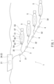
FIG. 1 is a schematic configuration diagram of an underwater towing system according to one embodiment. -
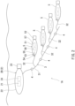
FIG. 2 is a schematic configuration diagram of the underwater towing system according to a modified example. -
FIG. 3 is a schematic configuration diagram of the underwater towing system according to another modified example. -
FIG. 1 shows anunderwater towing system 1 according to one embodiment. Theunderwater towing system 1 includes atowing structure 2 andunderwater work structures 5. In the present embodiment, thetowing structure 2 is asupport ship 2A that sails on water. - A
towing rope 3 hangs down from thetowing structure 2 into water. Theunderwater work structures 5 are towed by thetowing rope 3. In the present embodiment, thetowing rope 3 includes: amain line 31 connected to thetowing structure 2; andbranch lines 32 that extend from themain line 31 and are used for connection with theunderwater work structures 5. However, thebranch lines 32 are not necessarily required, and theunderwater work structures 5 may be directly connected to themain line 31. - At least one
light emitter 4 is attached to thetowing rope 3. Thelight emitter 4 is, for example, a LED. In the present embodiment, thelight emitters 4, the number of which is equal to the number ofunderwater work structures 5, are attached to themain line 31 of thetowing rope 3. However, the number oflight emitters 4 does not necessarily have to be equal to the number ofunderwater work structures 5 and may be smaller or larger than the number ofunderwater work structures 5. Moreover, thelight emitters 4 may be attached to not themain line 31 of thetowing rope 3 but thebranch lines 32 or may be attached to both of themain line 31 and thebranch lines 32. - The
towing structure 2 includesfirst control circuitry 21 configured to control thelight emitters 4. To be specific, thefirst control circuitry 21 is electrically connected to all of thelight emitters 4. In the present embodiment, thefirst control circuitry 21 makes all of thelight emitters 4 transmit light signals of the same flashing pattern such that all of the light emitters 4 flash in synchronization with each other. To be specific, the flashing pattern includes: information indicating which of the underwater work structures 5 a command is directed to; and a content of the command. - Regarding the
first control circuitry 21 and below-describedsecond control circuitry 56, the functionality of the elements disclosed herein may be implemented using circuitry or processing circuitry which includes general purpose processors, special purpose processors, integrated circuits, ASICs ("Application Specific Integrated Circuits"), conventional circuitry and/or combinations thereof which are configured or programmed to perform the disclosed functionality. Processors are considered processing circuitry or circuitry as they include transistors and other circuitry therein. In the disclosure, the circuitry, units, or means are hardware that carry out or are programmed to perform the recited functionality. The hardware may be any hardware disclosed herein or otherwise known which is programmed or configured to carry out the recited functionality. When the hardware is a processor which may be considered a type of circuitry, the circuitry, means, or units are a combination of hardware and software, the software being used to configure the hardware and/or processor. - The number of
underwater work structures 5 is four in the illustrated example but may be two, three, or five or more. In the present embodiment, theunderwater work structures 5 are AUVs. Specifically, eachunderwater work structure 5 that is the AUV includes: amain body 51 having a streamline shape; and apropulsor 52 located at themain body 51. - The
propulsor 52 can apply thrust to themain body 51 in a front-rear direction, left-right direction, and upper-lower direction of themain body 51. In addition, thepropulsor 52 can apply turning force to themain body 51 in a yaw direction around an upper-lower axis of themain body 51 and a pitch direction around a left-right axis of themain body 51. For example, thepropulsor 52 may include thrusters that are directed in different directions from each other or may include a single thruster of a swing type. - A
light receiver 53, an engager 54, and anactuator 55 are located at a front portion of themain body 51. Thelight receiver 53 can receive the light signal from thelight emitter 4. The engager 54 can be connected to thebranch line 32 of thetowing rope 3. Theactuator 55 operates the engager 54. Moreover, thesecond control circuitry 56 and an inertial navigation system 57 (INS) are located at themain body 51. - The
second control circuitry 56 is electrically connected to thelight receiver 53, theactuator 55, and theinertial navigation system 57. Thesecond control circuitry 56 reads the command from thefirst control circuitry 21 in such a manner that thelight receiver 53 receives the light signal when the light signal from thelight emitter 4 includes the command directed to theunderwater work structure 5 on which thissecond control circuitry 56 is mounted. - The engager 54 includes, for example, a hook that can swing. In this case, the
actuator 55 makes the hook swing. Theactuator 55 is controlled by thesecond control circuitry 56. - The
inertial navigation system 57 includes: accelerometers that detect respective accelerations in directions in which three axes orthogonal to each other extend; and gyro sensors that detect respective angular velocities around the three axes. Theinertial navigation system 57 calculates a movement direction of themain body 51 from a reference position of themain body 51 and a movement distance of themain body 51 from the reference position of themain body 51, and calculates a current posture of themain body 51. After theunderwater work structure 5 separates from thetowing rope 3, thesecond control circuitry 56 controls thepropulsor 52 based on calculation results of theinertial navigation system 57. - Next, control performed by the
first control circuitry 21 and thesecond control circuitry 56 will be described in detail. - When the
towing structure 2 reaches a target place of eachunderwater work structure 5, thefirst control circuitry 21 makes thelight emitter 4 transmit a separation signal for theunderwater work structure 5 to be located. The target places of all of theunderwater work structures 5 may be the same as each other or may be different from each other. - The
second control circuitry 56 of eachunderwater work structure 5 determines based on the flashing pattern of the light signal received by thelight receiver 53 whether or not the light signal is the separation signal for thisunderwater work structure 5. When thelight receiver 53 of eachunderwater work structure 5 receives the separation signal for thisunderwater work structure 5, thesecond control circuitry 56 drives theactuator 55 such that thetowing rope 3 and theengager 54 are disconnected from each other. Thus, theunderwater work structure 5 separates from thetowing rope 3. - As described above, according to the
underwater towing system 1 of the present embodiment, theunderwater work structures 5 are towed by the towingrope 3 that hangs down from thetowing structure 2 into water. Therefore, theunderwater work structures 5 can be conveyed to the target places by the sailing of thetowing structure 2. Moreover, when eachunderwater work structure 5 is conveyed to the target place, and thefirst control circuitry 21 makes thelight emitter 4 transmit the separation signal for theunderwater work structure 5, theunderwater work structure 5 separates from the towingrope 3 at the target place. Therefore, theunderwater work structures 5 can be located at the target places. - The present disclosure is not limited to the above embodiment, and various modifications may be made within the scope of the present disclosure.
- For example, the
underwater work structures 5 may include respective light emitters, and light receivers corresponding to these light emitters may be attached to the towingrope 3 and electrically connected to thefirst control circuitry 21. According to this configuration, information can be output from theunderwater work structures 5 to thefirst control circuitry 21. In this case, it is desirable that the color of the light signal transmitted from thelight emitter 4 of the towingrope 3 and the color of the light signal transmitted from the light emitter of theunderwater work structure 5 be different from each other. It is desirable that when the light emitters of all of theunderwater work structures 5 emit light in the same color, the light emission of the light emitter of eachunderwater work structure 5 be controlled by a light emission permission command supplied from thefirst control circuitry 21 of thetowing structure 2 for thisunderwater work structure 5. - Moreover, as in an
underwater towing system 1A according to a modified example shown inFIG. 2 , thetowing structure 2 may be anAUV 2B that sails in water. TheAUV 2B includes a battery larger than that of the AUV that is theunderwater work structure 5. TheAUV 2B can sail in water for a long period of time. Moreover, theAUV 2B includes: amain body 22 having a streamline shape; and apropulsor 23 located at themain body 22. Thefirst control circuitry 21 and aninertial navigation system 24 are located at themain body 22. - Moreover, as in an
underwater towing system 1B according to another modified example shown inFIG. 3 , eachunderwater work structure 5 may not include the engager 54 and theactuator 55. In this case, theunderwater work structure 5 that is the AUV is towed by the towingrope 3 by sailing while being guided by the light signal from thelight emitter 4. When theunderwater work structures 5 are guided by the light signals from thelight emitters 4, the number oflight emitters 4 and the number ofunderwater work structures 5 may be equal to each other or may be different from each other as with the above. - According to this configuration, the
underwater work structures 5 can be indirectly towed by the towingrope 3 without being connected to the towingrope 3. On the other hand, in a case where eachunderwater work structure 5 includes the engager 54 and theactuator 55 as in the above embodiment, when theunderwater work structure 5 is towed by the towingrope 3, theunderwater work structure 5 can be mechanically connected to the towing rope 3 (direct towing). - According to the
underwater towing system 1B shown inFIG. 3 , when thelight receiver 53 of eachunderwater work structure 5 receives the separation signal for thisunderwater work structure 5 from thelight emitter 4, thesecond control circuitry 56 changes from a following mode in which theunderwater work structure 5 sails while following thelight emitter 4 to a work mode in which theunderwater work structure 5 performs underwater work. Thus, theunderwater work structure 5 separates from the towingrope 3. - Moreover, the
underwater work structure 5 does not necessarily have to be the AUV and may be underwater observation equipment. The underwater observation equipment may include a propulsor or may not include a propulsor. - As a first aspect, the present disclosure provides an underwater towing system including: a towing structure sailing on or in water and including control circuitry; a towing rope hanging down from the towing structure into the water; at least one light emitter attached to the towing rope and controlled by the control circuitry; and underwater work structures towed by the towing rope, wherein: each of the underwater work structures includes a light receiver that receives a light signal from the at least one light emitter; and one of the underwater work structures separates from the towing rope when the control circuitry makes the at least one light emitter transmit a separation signal for this underwater work structure, and the light receiver of this underwater work structure receives the separation signal.
- According to the above configuration, the underwater work structures are towed by the towing rope hanging down from the towing structure into the water. Therefore, the underwater work structures can be conveyed to the target places by the sailing of the towing structure. Moreover, when each underwater work structure is conveyed to the target place, and the control circuitry makes the light emitter transmit the separation signal for the underwater work structure, the underwater work structure separates from the towing rope at the target place. Therefore, the underwater work structures can be located at the target places.
- As a second aspect, the underwater towing system may be configured such that: in the first aspect, the control circuitry includes first control circuitry; each of the underwater work structures includes an engager that is connectable to the towing rope, an actuator that operates the engager, and second control circuitry configured to control the actuator; and when the light receiver receives the separation signal, the second control circuitry drives the actuator such that the towing rope and the engager are disconnected from each other. According to this configuration, when towing the underwater work structures by the towing rope, the underwater work structures can be mechanically connected to the towing rope.
- As a third aspect, the underwater towing system may be configured such that in the first or second aspect, for example, each of the underwater work structures includes an autonomous underwater vehicle.
- As a fourth aspect, the underwater towing system may be configured such that in the first aspect, each of the underwater work structures includes an autonomous underwater vehicle including a propulsor and is indirectly towed by the towing rope by sailing while being guided by the light signal from the at least one light emitter. According to this configuration, the underwater work structures can be towed by the towing rope without being connected to the towing rope.
Claims (4)
- An underwater towing system comprising:a towing structure sailing on or in water and including control circuitry;a towing rope hanging down from the towing structure into the water;at least one light emitter attached to the towing rope and controlled by the control circuitry; andunderwater work structures towed by the towing rope, wherein:each of the underwater work structures includes a light receiver that receives a light signal from the at least one light emitter; andone of the underwater work structures separates from the towing rope when the control circuitry makes the at least one light emitter transmit a separation signal for this underwater work structure, and the light receiver of this underwater work structure receives the separation signal.
- The underwater towing system according to claim 1, wherein:the control circuitry includes first control circuitry;each of the underwater work structures includesan engager that is connectable to the towing rope,an actuator that operates the engager, andsecond control circuitry configured to control the actuator; andwhen the light receiver receives the separation signal, the second control circuitry drives the actuator such that the towing rope and the engager are disconnected from each other.
- The underwater towing system according to claim 1 or 2, wherein each of the underwater work structures includes an autonomous underwater vehicle.
- The underwater towing system according to claim 1, wherein each of the underwater work structures includes an autonomous underwater vehicle including a propulsor and is indirectly towed by the towing rope by sailing while being guided by the light signal from the at least one light emitter.
Applications Claiming Priority (2)
| Application Number | Priority Date | Filing Date | Title |
|---|---|---|---|
| JP2022099740 | 2022-06-21 | ||
| PCT/JP2023/020222 WO2023248740A1 (en) | 2022-06-21 | 2023-05-31 | Underwater towing system |
Publications (2)
| Publication Number | Publication Date |
|---|---|
| EP4545399A1 true EP4545399A1 (en) | 2025-04-30 |
| EP4545399A4 EP4545399A4 (en) | 2026-06-17 |
Family
ID=89379829
Family Applications (1)
| Application Number | Title | Priority Date | Filing Date |
|---|---|---|---|
| EP23826927.8A Pending EP4545399A4 (en) | 2022-06-21 | 2023-05-31 | UNDERWATER TOWING SYSTEM |
Country Status (3)
| Country | Link |
|---|---|
| EP (1) | EP4545399A4 (en) |
| JP (1) | JP7880421B2 (en) |
| WO (1) | WO2023248740A1 (en) |
Family Cites Families (9)
| Publication number | Priority date | Publication date | Assignee | Title |
|---|---|---|---|---|
| DE102005045843B4 (en) * | 2005-09-26 | 2017-04-06 | Thyssenkrupp Marine Systems Gmbh | Coupling device for releasably connecting a towed antenna |
| BRPI0810436A2 (en) * | 2007-04-17 | 2014-10-14 | Woods Hole Oceanographic Inst | Underwater Tying Systems and Methods |
| JP2010139270A (en) * | 2008-12-09 | 2010-06-24 | Mitsubishi Heavy Ind Ltd | System for collecting under-water information |
| DE102009053742B4 (en) * | 2009-11-18 | 2012-01-26 | Atlas Elektronik Gmbh | Unmanned underwater vehicle and device for connecting a fiber optic cable to an unmanned underwater vehicle |
| FR2965543B1 (en) * | 2010-10-01 | 2014-03-28 | Ifremer | SYSTEM COMPRISING A SUBMARINE ENGINE AND A BASE LOCATED ON A SURFACE |
| CN204297038U (en) * | 2014-08-01 | 2015-04-29 | 杨永鑫 | Steamer main cabin escape device |
| JP2016132406A (en) * | 2015-01-21 | 2016-07-25 | 三菱重工業株式会社 | Underwater vehicle lifting system |
| US10807680B2 (en) * | 2016-10-21 | 2020-10-20 | National Tsing Hua University | Mooring system and method for power generation systems and other payloads in water flows |
| JP6991544B2 (en) | 2017-03-31 | 2022-01-12 | 国立研究開発法人 海上・港湾・航空技術研究所 | Underwater vehicle control method and underwater vehicle control system |
-
2023
- 2023-05-31 JP JP2024528681A patent/JP7880421B2/en active Active
- 2023-05-31 WO PCT/JP2023/020222 patent/WO2023248740A1/en not_active Ceased
- 2023-05-31 EP EP23826927.8A patent/EP4545399A4/en active Pending
Also Published As
| Publication number | Publication date |
|---|---|
| JPWO2023248740A1 (en) | 2023-12-28 |
| WO2023248740A1 (en) | 2023-12-28 |
| EP4545399A4 (en) | 2026-06-17 |
| JP7880421B2 (en) | 2026-06-25 |
Similar Documents
| Publication | Publication Date | Title |
|---|---|---|
| EP3699714A2 (en) | Control system for boats | |
| US7854569B1 (en) | Underwater unmanned vehicle recovery system and method | |
| US12084155B2 (en) | Assisted docking graphical user interface systems and methods | |
| ES2865195T3 (en) | A procedure and system for operating one or more tugs | |
| US6600695B1 (en) | Method and apparatus for retrieving an unmanned underwater vehicle | |
| JP5438906B2 (en) | Launch recovery system for underwater vehicle and ship equipped with this launch recovery system | |
| US20150336650A1 (en) | Coupling provisions for diver propulsion vehicle | |
| US11738847B2 (en) | Interface unit | |
| US11691704B2 (en) | Posture control system for hull and marine vessel | |
| WO2019011451A1 (en) | A control arrangement | |
| EP4353578A1 (en) | Mooring system and mooring method | |
| US11124279B2 (en) | Submarine vehicle and control method | |
| JP2019162922A (en) | Maneuvering support system, naval vessel, and maneuvering support method | |
| US11312461B1 (en) | Boat maneuvering control system for boat and boat maneuvering control method for boat | |
| CN108255176B (en) | Method for autonomously and cooperatively recovering ships by double unmanned boats | |
| KR102841046B1 (en) | Port monitoring system using underwater vehicle and method thereof | |
| US5964175A (en) | Conformal detachable platform array | |
| CN115892405A (en) | Underwater Split Carrying Equipment | |
| EP3649518A1 (en) | Use of a wireless control system to direct an unmanned watercraft to a first position during a launch or a recovery situation | |
| WO2023248740A1 (en) | Underwater towing system | |
| KR102542896B1 (en) | Autonomous Boat, Autonomous System, And Method Of Controlling Autonomous System | |
| Bruzzone et al. | Autonomous mine hunting mission for the Charlie USV | |
| JPH07165189A (en) | Automatic position maintaining device | |
| KR102227893B1 (en) | Supplementary Towing System for Enhancing Stability using Thrusters | |
| KR102731605B1 (en) | ship mooring line connection system |
Legal Events
| Date | Code | Title | Description |
|---|---|---|---|
| STAA | Information on the status of an ep patent application or granted ep patent |
Free format text: STATUS: THE INTERNATIONAL PUBLICATION HAS BEEN MADE |
|
| PUAI | Public reference made under article 153(3) epc to a published international application that has entered the european phase |
Free format text: ORIGINAL CODE: 0009012 |
|
| STAA | Information on the status of an ep patent application or granted ep patent |
Free format text: STATUS: REQUEST FOR EXAMINATION WAS MADE |
|
| 17P | Request for examination filed |
Effective date: 20241007 |
|
| AK | Designated contracting states |
Kind code of ref document: A1 Designated state(s): AL AT BE BG CH CY CZ DE DK EE ES FI FR GB GR HR HU IE IS IT LI LT LU LV MC ME MK MT NL NO PL PT RO RS SE SI SK SM TR |
|
| DAV | Request for validation of the european patent (deleted) | ||
| DAX | Request for extension of the european patent (deleted) | ||
| REG | Reference to a national code |
Ref country code: DE Ref legal event code: R079 Free format text: PREVIOUS MAIN CLASS: B63C0011000000 Ipc: B63B0021660000 |
|
| A4 | Supplementary search report drawn up and despatched |
Effective date: 20260515 |
|
| RIC1 | Information provided on ipc code assigned before grant |
Ipc: B63B 21/66 20060101AFI20260508BHEP |