EP4545379A1 - Train control system and train control method - Google Patents
Train control system and train control method Download PDFInfo
- Publication number
- EP4545379A1 EP4545379A1 EP23825382.7A EP23825382A EP4545379A1 EP 4545379 A1 EP4545379 A1 EP 4545379A1 EP 23825382 A EP23825382 A EP 23825382A EP 4545379 A1 EP4545379 A1 EP 4545379A1
- Authority
- EP
- European Patent Office
- Prior art keywords
- time
- alarm
- train
- railroad crossing
- departure
- Prior art date
- Legal status (The legal status is an assumption and is not a legal conclusion. Google has not performed a legal analysis and makes no representation as to the accuracy of the status listed.)
- Pending
Links
Images


Classifications
-
- B—PERFORMING OPERATIONS; TRANSPORTING
- B61—RAILWAYS
- B61L—GUIDING RAILWAY TRAFFIC; ENSURING THE SAFETY OF RAILWAY TRAFFIC
- B61L29/00—Safety means for rail/road crossing traffic
- B61L29/24—Means for warning road traffic that a gate is closed or closing, or that rail traffic is approaching, e.g. for visible or audible warning
- B61L29/28—Means for warning road traffic that a gate is closed or closing, or that rail traffic is approaching, e.g. for visible or audible warning electrically operated
- B61L29/32—Timing, e.g. advance warning of approaching train
-
- B—PERFORMING OPERATIONS; TRANSPORTING
- B61—RAILWAYS
- B61L—GUIDING RAILWAY TRAFFIC; ENSURING THE SAFETY OF RAILWAY TRAFFIC
- B61L27/00—Central railway traffic control systems; Trackside control; Communication systems specially adapted therefor
- B61L27/10—Operations, e.g. scheduling or time tables
- B61L27/12—Preparing schedules
-
- B—PERFORMING OPERATIONS; TRANSPORTING
- B61—RAILWAYS
- B61L—GUIDING RAILWAY TRAFFIC; ENSURING THE SAFETY OF RAILWAY TRAFFIC
- B61L27/00—Central railway traffic control systems; Trackside control; Communication systems specially adapted therefor
- B61L27/10—Operations, e.g. scheduling or time tables
- B61L27/16—Trackside optimisation of vehicle or train operation
-
- B—PERFORMING OPERATIONS; TRANSPORTING
- B61—RAILWAYS
- B61L—GUIDING RAILWAY TRAFFIC; ENSURING THE SAFETY OF RAILWAY TRAFFIC
- B61L29/00—Safety means for rail/road crossing traffic
- B61L29/08—Operation of gates; Combined operation of gates and signals
- B61L29/18—Operation by approaching rail vehicle or train
- B61L29/22—Operation by approaching rail vehicle or train electrically
Definitions
- the present invention relates to a train control system and a train control method.
- the present invention relates to the train control system and the train control method that is applicable to a case where a railroad crossing exists on a track.
- PTL 1 discloses a railroad crossing control device.
- the railroad crossing control device when the railroad crossing control device receives an instruction to stop an alarm sound of the railroad crossing from an operation management device because a failed train stops in a railroad crossing control section, the railroad crossing control device sends a stop request to an automatic train control device after reconfirming that the failed train stops at a station, and stops the alarm sound of the railroad crossing after receiving a response in which the train in a station yard has set in an immovable state from the automatic train control device.
- the railroad crossing control system includes an operation management device that manages operations of a plurality of trains based on train position information transmitted from on-board devices constituting a part of a wireless train control system, and a ground device that exchanges signals including information or instructions with the on-board devices, the railroad crossing control device, and the operation management device.
- the operation management device sends, to the ground device, an inhibition instruction to temporarily stop the operations of the trains.
- the ground device which has received the inhibition instruction, instructs the on-board devices to set a stop limit, and instructs the railroad crossing control device to interrupt alarm control.
- an alarm time required until the train arrives after the alarm is restarted has to be secured depending on the scale of the railroad crossing in order to ensure the safety of people and the like who cross the railroad crossing.
- the time from the restart of the alarm to arrival of the train at the railroad crossing becomes longer than necessary. This prolongs the alarm time of the railroad crossing.
- the train starts traveling early if the train is close to the railroad crossing, the alarm time until the train arrives is shortened, and thus the safety of people who cross the railroad crossing cannot be secured.
- An object of the present invention is to provide a train control system and a train control method capable of preventing an alarm time from being excessively prolonged while securing the alarm time from the restart of the alarm to the arrival of a train.
- the present invention is a train control system including an alarm start time acquisition unit that acquires an estimated alarm start time that is an estimated time of starting an alarm of a railroad crossing issued when a train passes through the railroad crossing, and a departure time calculation unit that calculates a departure time of the train at a predetermined stop spot depending on the estimated alarm start time that has been acquired.
- the train control system further includes a railroad crossing information acquisition unit that acquires a travel time required for the train to travel to a control start point of the railroad crossing after departing from the stop spot.
- the departure time calculation unit can calculate the departure time based on the estimated alarm start time and the travel time. In this case, the train can be prevented from being excessively delayed while the alarm time is secured.
- the departure time calculation unit can set a time obtained by subtracting the travel time from the estimated alarm start time as the departure time. In this case, the departure time can be easily calculated.
- the travel time can be changed depending on trains.
- the train can be prevented from being excessively delayed while the alarm time is secured depending on trains.
- the travel time can be changed depending on at least one of vehicle performance and an operation type of a train. In this case, the travel time can be calculated more easily.
- the alarm start time acquisition unit can set a time obtained by adding an alarm stop time, which is a stop time of a designated alarm, to a railroad crossing alarm stop time, which is a time when the alarm of the railroad crossing stops, as the estimated alarm start time. This case makes it easier to acquire the estimated alarm start time of the railroad crossing.
- the alarm start time acquisition unit can acquire the alarm stop time designated depending on a volume of traffic obstructing the railroad crossing.
- the alarm stop time can be set depending on the volume of traffic.
- the alarm start time acquisition unit can acquire the alarm stop time designated depending on a railroad crossing alarm time which is a time during which the alarm of the railroad crossing continues.
- the alarm stop time can be set depending on the railroad crossing alarm time, and the alarm can be prevented from being excessively prolonged.
- the alarm start time acquisition unit then can set the railroad crossing alarm stop time when the alarm of the railroad crossing stops and no train is present between the stop spot and the control start point of the railroad crossing. In this case, an appropriate railroad crossing alarm stop time can be set.
- the departure time calculation unit can set an upper limit to the change amount of the departure time. This case makes it possible to prevent the train from being excessively delayed.
- the upper limit of the change amount can be a time margin of the train. In this case, the train is less likely to be delayed.
- the stop spot can be set to a railroad station. This case makes train operation management easier.
- a planned schedule can be created using the departure time.
- the planned schedule can be created depending on the state of the railroad crossing.
- the present invention is a train control method including acquiring an estimated alarm start time that is an estimated time of starting an alarm of a railroad crossing issued when a train passes through the railroad crossing, and calculating a departure time of the train at a predetermined stop spot depending on the estimated alarm start time that has been acquired.
- the present invention can provide a train control system and a train control method capable of preventing an alarm from being excessively prolonged while securing an alarm time from restart of the alarm to arrival of the train.
- a first embodiment will be first described.
- the commander of an operation management system stops the alarm of the railroad crossing 102 and further sets an estimated alarm start time for restarting the alarm. Then, the departure time of a train that is at a stop at a stop spot such as a station is adjusted depending on the estimated alarm start time.
- FIG. 1 is a conceptual diagram illustrating an overall configuration of an operation management system 1 according to the present embodiment.
- the illustrated operation management system 1 includes a down train 101a and an up train 101b, the railroad crossing 102, controllers 103a and 103b, stations 104a and 104b, tracks 105a and 105b, and a departure time determination device 201.
- the down train 101a is at a stop at the station 104a.
- the down train 101a travels from the left side to the right side in the drawing on the track 105a such as a railroad track.
- the controller 103a detects the down train 101a.
- the railroad crossing 102 operates and an alarm is issued.
- Td the time from when the down train 101a departs from the station 104a to when it arrives at the controller 103a is illustrated as a travel time Td.
- the up train 101b is at a stop at the station 104b.
- the up train 101b travels from the right side to the left side in the drawing on the track 105b such as a railroad track.
- the controller 103b detects the up train 101b.
- the railroad crossing 102 operates and an alarm is issued.
- the time from when the up train 101b departs from the station 104b to when it arrives at the controller 103b is illustrated as a travel time Tu.
- the departure time determination device 201 is an example of a train control system.
- the departure time determination device 201 determines a departure time of the down train 101a at the station 104a.
- the departure time determination device 201 determines a departure time of the up train 101b at the station 104b.
- the departure time determination device 201 is a computer device.
- the departure time determination device 201 includes, for example, a central processing unit (CPU) that controls each unit through execution of a program, and a display that displays an image and other information.
- the departure time determination device 201 includes, for example, a keyboard for inputting characters and the like, and a touch pad as a pointing device.
- the departure time determination device 201 includes, for example, a communication module used for communication with an external device, an internal memory in which system data and internal data are stored, an external memory as an auxiliary storage device, and the like.
- FIG. 2 is a block diagram illustrating a functional configuration example of the departure time determination device 201.
- the illustrated departure time determination device 201 includes a railroad crossing information storage device 202 that stores information about a railroad crossing, a railroad crossing information acquisition unit 203 that acquires the information about the railroad crossing from the railroad crossing information storage device 202, a departure time calculation unit 204 that calculates departure times of the down train 101a and the up train 101b, an alarm start time acquisition unit 205 that acquires an alarm start time of the railroad crossing 102, and a departure time output unit 206 that outputs the calculated departure time.
- the railroad crossing information storage device 202 is an example of a railroad crossing information storage unit.
- the railroad crossing information storage device 202 stores, as the information about the railroad crossing 102, a travel time taken for the down train 101a and the up train 101b to travel to a control start point of the railroad crossing 102 after departing from a stop spot.
- the stop spot of the down train 101a is the station 104a
- the stop spot of the up train 101b is the station 104b.
- the control start point of the railroad crossing 102 is the controller 103a in the case of the down train 101a, and is the controller 103b in the case of the up train 101b. That is, the railroad crossing information storage device 202 stores the travel times Td and Tu illustrated in FIG. 1 .
- the railroad crossing information acquisition unit 203 acquires the travel times Td and Tu as the information about the railroad crossing 102 from the railroad crossing information storage device 202.
- the departure time calculation unit 204 calculates the departure times of the down train 101a and the up train 101b at predetermined stop spots depending on an estimated alarm start time Tp acquired by the alarm start time acquisition unit 205. That is, the departure time calculation unit 204 calculates the departure time of the down train 101a at the station 104a depending on the estimated alarm start time Tp. Further, the departure time calculation unit 204 calculates the departure time of the up train 101b at the station 104b depending on the estimated alarm start time Tp. As will be described in detail later, the departure time calculation unit 204 calculates the departure times based on the alarm start time and the travel times Td and Tu.
- the alarm start time acquisition unit 205 acquires an estimated alarm start time Tp, which is an estimated time at which the alarm of the railroad crossing 102 starts.
- Tp an estimated time at which the alarm of the railroad crossing 102 starts.
- the alarm is issued when the down train 101a and the up train 101b pass through the railroad crossing 102.
- the departure time output unit 206 transmits the departure times calculated by the departure time calculation unit 204 to the operation management system.
- the departure time determination device 201 is a device that determines the departure time of the down train 101a at the station 104a and the departure time of the up train 101a at the station 104b depending on the estimated alarm start time Tp, which is the time to restart the alarm, after the alarm of the railroad crossing 102 is stopped by the instruction from the commander.
- the commander may set the estimated alarm start time Tp when issuing the instruction to stop the alarm of the railroad crossing 102, or may check the state of the railroad crossing 102 after stopping the alarm of the railroad crossing 102 to determine and set the estimated alarm start time Tp.
- the estimated alarm start time Tp that has been set is input to the departure time determination device 201.
- the estimated alarm start time Tp that has been input is acquired by the alarm start time acquisition unit 205 and sent to the departure time calculation unit 204.
- the railroad crossing information storage device 202 is a storage device that holds, for each railroad crossing 102, the travel time Td from departure of the down train 101a from the station 104a to arrival at the down controller 103a of the railroad crossing 102 between stations, and the travel time Tu from departure of the up train 101b from the station 104b to arrival at the up controller 103b.
- the departure time calculation unit 204 refers to the railroad crossing information storage device 202 via the railroad crossing information acquisition unit 203 to acquire the travel times Td and Tu.
- the travel times Td and Tu may be calculated using a standard run curve created as a travel plan of trains between stations. Since the standard run curve is given as a speed at each position between stations, the time when the down train 101a arrives at the controller 103a after departing from the station 104a can be calculated using the standard run curve. Similarly, the time when the up train 101b arrives at the controller 103b after departing from the station 104b can be calculated using the standard run curve.
- the travel times Td and Tu may be changed depending on the down train 101a and the up train 101b. That is, the travel times Td and Tu may be changed depending on operation types and vehicle types of the down train 101a and the up train 101b.
- the travel times Td and Tu may be changed by changing the standard run curves between an express train and a local train.
- the travel times Td and Tu may be changed depending on vehicle performance.
- the travel times Td and Tu may be changed depending on adjustable speed performance of a vehicle.
- the departure time calculation unit 204 that has acquired the travel times Td and Tu calculates the departure time of the down train 101a at the station 104a in a manner that Tp - Td. Similarly, the departure time calculation unit 204 calculates the departure time of the up train 101b at the station 104b in a manner that Tp - Tu. That is, the departure time calculation unit 204 sets times obtained respectively by subtracting the travel times Td and Tu from the estimated alarm start time Tp as the departure times. The departure time determination device 201 then transmits the calculated departure times to the operation management system via the departure time output unit 206. The operation management system makes control such as course control on the down train 101a and the up train 101b using the received departure times.
- the departure time calculation unit 204 may set upper limits for the change amounts of the departure times. For example, a time margin of the travel time during which a delay can be recovered between stations is determined as the upper limit of the change amount of the departure time. In a case where the departure time calculated by the departure time calculation unit 204 exceeds the upper limit, the time obtained by adding the change amount of the upper limit to the departure time in the planned schedule is set as the departure time. Further, a delay recovery operation for recovering a delay may be performed after passing through the railroad crossing 102.
- the delay recovery operation When the delay recovery operation is performed before arrival of a train at the railroad crossing 102 and the train travels at a speed higher than that of the standard run curve, the alarm time required for the train to arrive at the railroad crossing 102 after the alarm starts might be insufficient. Therefore, by performing the delay recovery operation after passing through the railroad crossing 102, the safety of the railroad crossing 102 can be improved.
- the controller 103 is installed at a position where it takes a necessary alarm time from the start of the alarm to the arrival of the train when the train travels using the standard run curve from the position of the controller 103 to the railroad crossing 102. Therefore, the train 101 can be controlled so that the train 101 arrives at the controller 103 at the estimated alarm start time Tp. Therefore, the alarm starts at the estimated alarm start time Tp, and the alarm time can be prevented from being prolonged while a necessary alarm time is being secured.
- the controllers 103a and 103b are illustrated as the controller 103 in FIG. 1 , the controller 103 may be virtual. That is, the controller 103 is not actually installed, and the alarm of the railroad crossing 102 may be started when the train 101 arrives at the position corresponding to the position of the controller 103.
- one of the plurality of the railroad crossings 102 can be selected to determine a departure time.
- the railroad crossing 102 having a large volume of crossing the railroad crossing 102 may be selected.
- the train arrives at the controller 103 at the estimated alarm restart time of the railroad crossing 102, and the alarm of the railroad crossing 102 can be restarted. Therefore, it is possible to prevent the alarm from being excessively prolonged while securing the alarm time required until the train 101 arrives after the alarm of the railroad crossing 102 is restarted.
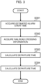
- FIG. 3 is a flowchart explaining processing performed when the departure time determination device 201 calculates the departure times of the down train 101a and the up train 101b.
- the departure time determination device 201 executes the processing illustrated in FIG. 3 when acquiring the estimated alarm start time Tp.
- the alarm start time acquisition unit 205 acquires the estimated alarm start time Tp determined by setting by the commander or the like (step S301).
- the railroad crossing information acquisition unit 203 acquires the travel times Td and Tu held as the information about the railroad crossing by the railroad crossing information storage device 202. That is, the railroad crossing information acquisition unit 203 acquires the travel time Td from the departure of the down train 101a from a station to the arrival of this train at the down controller 103a and the travel time Tu from the departure of the up train 101b from the station to the arrival of this train at the up controller 103b (step S302).
- the departure time calculation unit 204 calculates the departure time of the down train 101a and the departure time of the up train 101b by using the estimated alarm start time Tp acquired in step S301 and the travel times Td and Tu acquired in step S302 (step S303). Specifically, the departure time of the down train 101a is set as Tp - Td, and the departure time of the up train 101b is set as Tp - Tu.
- the departure time calculation unit 204 then transmits the departure times calculated in step S303 to the operation management system via the departure time output unit 206, and ends the processing (step S304).
- the departure time of the train 101 at the station 104 is determined depending on the time for traveling from the station 104 to the controller 103 and the estimated alarm restart time at the railroad crossing 102.
- the alarm of the railroad crossing 102 can be restarted just at the estimated alarm restart time. Therefore, it is possible to prevent the alarm from being excessively prolonged while securing the alarm time required until the arrival of the train 101 after the alarm of the railroad crossing 102 restarts. In addition, the safety of people who cross the railroad crossing 102 can be secured.
- the commander sets an alarm stop time Ts which is a time for stopping the alarm instead of setting the estimated alarm start time Tp.
- the departure time determination device 201 then calculates the estimated alarm start time Tp based on the alarm stop time Ts.
- the alarm start time acquisition unit 205 acquires an instruction to stop the alarm of the railroad crossing 102 from the commander and the alarm stop time Ts set by the commander. That is, the alarm start time acquisition unit 205 acquires the alarm stop time Ts instead of the estimated alarm start time Tp (see parentheses in FIG. 2 ).
- the alarm start time acquisition unit 205 outputs an instruction to prevent departure of the train 101 from the station 104 to the operation management system until a departure time at the station 104 is determined. Thereafter, the alarm start time acquisition unit 205 sets, as a railroad crossing alarm stop time Te, the time when the alarm of the railroad crossing 102 stops and the train 101 is not present between the station 104 and the controller 103.
- the alarm start time acquisition unit 205 waits until the alarm of the railroad crossing stops after the train passes, and the time when the alarm stops is set as the railroad crossing alarm stop time Te. Further, in a case where another train is present between the station 104 and the controller 103, the alarm start time acquisition unit 205 waits until the another train passes through the railroad crossing 102 and the alarm stops even if the alarm of the railroad crossing 102 stops. Then, the time when the alarm stops after passage through the railroad crossing 102 is set as the railroad crossing alarm stop time Te.
- the alarm start time acquisition unit 205 sets, as the railroad crossing alarm stop time Te, the time when the instruction to stop the alarm of the railroad crossing 102 is acquired from the commander.
- the alarm start time acquisition unit 205 sets Te + Ts as the estimated alarm start time Tp. That is, the alarm start time acquisition unit 205 sets a time obtained by adding the alarm stop time Ts, which is a stop time of a designated alarm, to the railroad crossing alarm stop time Te, which is a time when the alarm of the railroad crossing stops, as the estimated alarm start time Tp. Thereafter, the same processing as in the first embodiment is performed to determine the departure times at the station 104. Note that the alarm start time acquisition unit 205 may acquire the alarm stop time Ts designated depending on the volume of traffic obstructing the railroad crossing 102.
- the alarm stop time Ts may be set to be long.
- the alarm stop time Ts may be set to be short.
- the alarm start time acquisition unit 205 can acquire the alarm stop time Ts designated depending on the railroad crossing alarm time, which is a time during which the alarm of the railroad crossing 102 continues.
- the railroad crossing alarm time is long (in a case where the alarm of the railroad crossing 102 continues for a long time)
- the alarm stop time Ts may be set to be long.
- the alarm stop time Ts may be set to be short.
- the alarm start time acquisition unit 205 By configuring the alarm start time acquisition unit 205 as described above, it is possible to stop the alarm of the railroad crossing 102 and determine the estimated alarm start time Tp automatically in consideration of the alarm state of the railroad crossing 102 and the presence position of a train on a railroad. As a result, the stop and restart of the alarm of the railroad crossing 102 are easier than those in the first embodiment.
- the departure time at the station 104 is determined at a planning stage. That is, the first embodiment and the second embodiment have described the configuration in which the alarm of the railroad crossing 102 is stopped in accordance with the instruction to stop the alarm of the railroad crossing 102 from the commander. According to this, the departure time of the train 101 is different from the time in the planned schedule.
- the alarm stop time Ts is set in advance at the time of creating the planned schedule, and the departure time of the train 101 is determined in advance depending on the set alarm stop time Ts. Then, the planned schedule is created using the departure time.
- the departure time in the planned schedule is calculated using the railroad crossing alarm stop time Te and the alarm stop time Ts described in the second embodiment.
- the departure times of the plurality of trains 101 in the planned schedule are determined depending on the alarm stop times Ts set for the respective trains.
- the railroad crossing alarm stop time Te which is the time when the train preceding the train 101 passes through the railroad crossing 102 and the alarm of the railroad crossing 102 stops, is calculated.
- Te + Ts is set as the estimated alarm start time Tp for the train 101.
- the same processing as in the first embodiment is performed to determine the departure time at the station 104, and the determined departure time is set as the departure time of the train 101 in the planned schedule.
- the departure times in the planned schedule are determined as described above.
- the departure times of the plurality of trains 101 for which the alarm stop time Ts is set are adjusted, and the trains travel in accordance with the schedule. This makes it possible to stop the alarm of the railroad crossing 102 during the alarm stop time Ts when the train 101 departs from the station.
- the predetermined stop spot is the railroad station 104.
- the present invention is not limited thereto, and the predetermined stop point may be a signal station which is a single passing track facility.
- the processing performed by the departure time determination device 201 can be understood as a train control method for acquiring an estimated alarm start time, which is an estimated time of starting the alarm of the railroad crossing 102 issued when the train 101 passes through the railroad crossing 102, and calculating the departure time of the train 101 at a predetermined stop spot, such as the station 104, depending on the estimated alarm start time that has been acquired.
- an estimated alarm start time which is an estimated time of starting the alarm of the railroad crossing 102 issued when the train 101 passes through the railroad crossing 102
- a predetermined stop spot such as the station 104
Landscapes
- Engineering & Computer Science (AREA)
- Mechanical Engineering (AREA)
- Train Traffic Observation, Control, And Security (AREA)
Abstract
A train control system includes an alarm start time acquisition unit 205 that acquires an estimated alarm start time that is an estimated time of starting an alarm of a railroad crossing issued when a train passes through the railroad crossing, and a departure time calculation unit 204 that calculates a departure time of the train at a predetermined stop spot depending on the estimated alarm start time that has been acquired. This can provide a train control system and a train control method capable of preventing the alarm from being excessively prolonged while securing an alarm time from restart of the alarm to arrival of the train.
Description
- The present invention relates to a train control system and a train control method. In particular, the present invention relates to the train control system and the train control method that is applicable to a case where a railroad crossing exists on a track.
- At railroad crossings on high-density rail lines in urban areas, the alarm times of the railroad crossings are prolonged, which is one of factors of traffic congestion around the railroad crossings. On the other hand, there exists a method for temporarily forcibly stopping alarms at the railroad crossings.
-
PTL 1 discloses a railroad crossing control device. In this disclosure, when the railroad crossing control device receives an instruction to stop an alarm sound of the railroad crossing from an operation management device because a failed train stops in a railroad crossing control section, the railroad crossing control device sends a stop request to an automatic train control device after reconfirming that the failed train stops at a station, and stops the alarm sound of the railroad crossing after receiving a response in which the train in a station yard has set in an immovable state from the automatic train control device. - PTL 2 discloses a railroad crossing control system. The railroad crossing control system includes an operation management device that manages operations of a plurality of trains based on train position information transmitted from on-board devices constituting a part of a wireless train control system, and a ground device that exchanges signals including information or instructions with the on-board devices, the railroad crossing control device, and the operation management device. The operation management device sends, to the ground device, an inhibition instruction to temporarily stop the operations of the trains. The ground device, which has received the inhibition instruction, instructs the on-board devices to set a stop limit, and instructs the railroad crossing control device to interrupt alarm control.
-
- PTL 1:
JP H11-78896 A - PTL 2:
JP 2016-141251 A - In a case where an alarm is restarted after the alarm of a railroad crossing is stopped, an alarm time required until the train arrives after the alarm is restarted has to be secured depending on the scale of the railroad crossing in order to ensure the safety of people and the like who cross the railroad crossing. There exists a method for uniformly securing a time from the restart of an alarm to the start of traveling of the train in order to secure the necessary alarm time when a train is at a stop at a stop spot such as a station. However, with this method, in a case where the train is at a stop at a position far from the railroad crossing, the time from the restart of the alarm to arrival of the train at the railroad crossing becomes longer than necessary. This prolongs the alarm time of the railroad crossing. On the other hand, when the train starts traveling early, if the train is close to the railroad crossing, the alarm time until the train arrives is shortened, and thus the safety of people who cross the railroad crossing cannot be secured.
- An object of the present invention is to provide a train control system and a train control method capable of preventing an alarm time from being excessively prolonged while securing the alarm time from the restart of the alarm to the arrival of a train.
- In order to solve the above problems, the present invention is a train control system including an alarm start time acquisition unit that acquires an estimated alarm start time that is an estimated time of starting an alarm of a railroad crossing issued when a train passes through the railroad crossing, and a departure time calculation unit that calculates a departure time of the train at a predetermined stop spot depending on the estimated alarm start time that has been acquired.
- Here, the train control system further includes a railroad crossing information acquisition unit that acquires a travel time required for the train to travel to a control start point of the railroad crossing after departing from the stop spot. The departure time calculation unit can calculate the departure time based on the estimated alarm start time and the travel time. In this case, the train can be prevented from being excessively delayed while the alarm time is secured.
- Further, the departure time calculation unit can set a time obtained by subtracting the travel time from the estimated alarm start time as the departure time. In this case, the departure time can be easily calculated.
- The travel time can be changed depending on trains. In this case, the train can be prevented from being excessively delayed while the alarm time is secured depending on trains.
- Further, the travel time can be changed depending on at least one of vehicle performance and an operation type of a train. In this case, the travel time can be calculated more easily.
- The alarm start time acquisition unit can set a time obtained by adding an alarm stop time, which is a stop time of a designated alarm, to a railroad crossing alarm stop time, which is a time when the alarm of the railroad crossing stops, as the estimated alarm start time. This case makes it easier to acquire the estimated alarm start time of the railroad crossing.
- Further, the alarm start time acquisition unit can acquire the alarm stop time designated depending on a volume of traffic obstructing the railroad crossing. In this case, the alarm stop time can be set depending on the volume of traffic.
- Furthermore, the alarm start time acquisition unit can acquire the alarm stop time designated depending on a railroad crossing alarm time which is a time during which the alarm of the railroad crossing continues. In this case, the alarm stop time can be set depending on the railroad crossing alarm time, and the alarm can be prevented from being excessively prolonged.
- The alarm start time acquisition unit then can set the railroad crossing alarm stop time when the alarm of the railroad crossing stops and no train is present between the stop spot and the control start point of the railroad crossing. In this case, an appropriate railroad crossing alarm stop time can be set.
- The departure time calculation unit can set an upper limit to the change amount of the departure time. This case makes it possible to prevent the train from being excessively delayed.
- The upper limit of the change amount can be a time margin of the train. In this case, the train is less likely to be delayed.
- The stop spot can be set to a railroad station. This case makes train operation management easier.
- Further, a planned schedule can be created using the departure time. In this case, the planned schedule can be created depending on the state of the railroad crossing.
- Further, the present invention is a train control method including acquiring an estimated alarm start time that is an estimated time of starting an alarm of a railroad crossing issued when a train passes through the railroad crossing, and calculating a departure time of the train at a predetermined stop spot depending on the estimated alarm start time that has been acquired.
- The present invention can provide a train control system and a train control method capable of preventing an alarm from being excessively prolonged while securing an alarm time from restart of the alarm to arrival of the train.
-
- [
FIG. 1] FIG. 1 is a conceptual diagram illustrating an overall configuration of an operation management system according to a present embodiment. - [
FIG. 2] FIG. 2 is a block diagram illustrating a functional configuration example of a departure time determination device. - [
FIG. 3] FIG. 3 is a flowchart explaining processing performed when a departure time calculation device calculates a departure time of a train. - Hereinafter, embodiments of the present invention will be described in detail with reference to the accompanying drawings.
- A first embodiment will be first described. In the first embodiment, in a case where the alarm time of a
railroad crossing 102 becomes long and this excessively obstructs people who cross therailroad crossing 102, the commander of an operation management system stops the alarm of therailroad crossing 102 and further sets an estimated alarm start time for restarting the alarm. Then, the departure time of a train that is at a stop at a stop spot such as a station is adjusted depending on the estimated alarm start time. - <Description of overall configuration of
operation management system 1 > -
FIG. 1 is a conceptual diagram illustrating an overall configuration of anoperation management system 1 according to the present embodiment. - The illustrated
operation management system 1 includes adown train 101a and an uptrain 101b, therailroad crossing 102,controllers stations tracks time determination device 201. - In the case of
FIG. 1 , thedown train 101a is at a stop at thestation 104a. Thedown train 101a travels from the left side to the right side in the drawing on thetrack 105a such as a railroad track. Thereafter, when arriving at thecontroller 103a, thecontroller 103a detects thedown train 101a. As a result, therailroad crossing 102 operates and an alarm is issued. InFIG. 1 , the time from when thedown train 101a departs from thestation 104a to when it arrives at thecontroller 103a is illustrated as a travel time Td. - In the case of
FIG. 1 , the uptrain 101b is at a stop at thestation 104b. The uptrain 101b travels from the right side to the left side in the drawing on thetrack 105b such as a railroad track. Thereafter, when arriving at thecontroller 103b, thecontroller 103b detects theup train 101b. As a result, therailroad crossing 102 operates and an alarm is issued. InFIG. 1 , the time from when theup train 101b departs from thestation 104b to when it arrives at thecontroller 103b is illustrated as a travel time Tu. - Note that, at the
railroad crossing 102, when the alarm is issued, vehicles and people that cross therailroad crossing 102 cannot pass. When thedown train 101a and theup train 101b pass through therailroad crossing 102, the alarm stops, and vehicles and people can pass. In a case where thedown train 101a and theup train 101b are not distinguished from each other, they may be simply referred to as a "train 101". In a case where thecontroller 103a and thecontroller 103b are not distinguished from each other, they may be simply referred to as a "controller 103". Further, in a case where thestation 104a and thestation 104b are not distinguished from each other, they may be simply referred to as a "station 104". - The departure
time determination device 201 is an example of a train control system. The departuretime determination device 201 determines a departure time of thedown train 101a at thestation 104a. The departuretime determination device 201 determines a departure time of theup train 101b at thestation 104b. - The departure
time determination device 201 is a computer device. The departuretime determination device 201 includes, for example, a central processing unit (CPU) that controls each unit through execution of a program, and a display that displays an image and other information. The departuretime determination device 201 includes, for example, a keyboard for inputting characters and the like, and a touch pad as a pointing device. Further, the departuretime determination device 201 includes, for example, a communication module used for communication with an external device, an internal memory in which system data and internal data are stored, an external memory as an auxiliary storage device, and the like. -
FIG. 2 is a block diagram illustrating a functional configuration example of the departuretime determination device 201. - The illustrated departure
time determination device 201 includes a railroad crossinginformation storage device 202 that stores information about a railroad crossing, a railroad crossinginformation acquisition unit 203 that acquires the information about the railroad crossing from the railroad crossinginformation storage device 202, a departuretime calculation unit 204 that calculates departure times of thedown train 101a and theup train 101b, an alarm starttime acquisition unit 205 that acquires an alarm start time of therailroad crossing 102, and a departuretime output unit 206 that outputs the calculated departure time. - The railroad crossing
information storage device 202 is an example of a railroad crossing information storage unit. The railroad crossinginformation storage device 202 stores, as the information about therailroad crossing 102, a travel time taken for thedown train 101a and theup train 101b to travel to a control start point of therailroad crossing 102 after departing from a stop spot. In this case, the stop spot of thedown train 101a is thestation 104a, and the stop spot of theup train 101b is thestation 104b. Further, the control start point of therailroad crossing 102 is thecontroller 103a in the case of thedown train 101a, and is thecontroller 103b in the case of theup train 101b. That is, the railroad crossinginformation storage device 202 stores the travel times Td and Tu illustrated inFIG. 1 . - The railroad crossing
information acquisition unit 203 acquires the travel times Td and Tu as the information about the railroad crossing 102 from the railroad crossinginformation storage device 202. - The departure
time calculation unit 204 calculates the departure times of thedown train 101a and theup train 101b at predetermined stop spots depending on an estimated alarm start time Tp acquired by the alarm starttime acquisition unit 205. That is, the departuretime calculation unit 204 calculates the departure time of thedown train 101a at thestation 104a depending on the estimated alarm start time Tp. Further, the departuretime calculation unit 204 calculates the departure time of theup train 101b at thestation 104b depending on the estimated alarm start time Tp. As will be described in detail later, the departuretime calculation unit 204 calculates the departure times based on the alarm start time and the travel times Td and Tu. - The alarm start
time acquisition unit 205 acquires an estimated alarm start time Tp, which is an estimated time at which the alarm of the railroad crossing 102 starts. The alarm is issued when thedown train 101a and theup train 101b pass through therailroad crossing 102. - The departure
time output unit 206 transmits the departure times calculated by the departuretime calculation unit 204 to the operation management system. - The departure
time determination device 201 is a device that determines the departure time of thedown train 101a at thestation 104a and the departure time of theup train 101a at thestation 104b depending on the estimated alarm start time Tp, which is the time to restart the alarm, after the alarm of therailroad crossing 102 is stopped by the instruction from the commander. The commander may set the estimated alarm start time Tp when issuing the instruction to stop the alarm of therailroad crossing 102, or may check the state of therailroad crossing 102 after stopping the alarm of therailroad crossing 102 to determine and set the estimated alarm start time Tp. The estimated alarm start time Tp that has been set is input to the departuretime determination device 201. The estimated alarm start time Tp that has been input is acquired by the alarm starttime acquisition unit 205 and sent to the departuretime calculation unit 204. The railroad crossinginformation storage device 202 is a storage device that holds, for eachrailroad crossing 102, the travel time Td from departure of thedown train 101a from thestation 104a to arrival at thedown controller 103a of therailroad crossing 102 between stations, and the travel time Tu from departure of theup train 101b from thestation 104b to arrival at the upcontroller 103b. Upon receiving the estimated alarm start time Tp, the departuretime calculation unit 204 refers to the railroad crossinginformation storage device 202 via the railroad crossinginformation acquisition unit 203 to acquire the travel times Td and Tu. - The travel times Td and Tu may be calculated using a standard run curve created as a travel plan of trains between stations. Since the standard run curve is given as a speed at each position between stations, the time when the
down train 101a arrives at thecontroller 103a after departing from thestation 104a can be calculated using the standard run curve. Similarly, the time when theup train 101b arrives at thecontroller 103b after departing from thestation 104b can be calculated using the standard run curve. The travel times Td and Tu may be changed depending on thedown train 101a and theup train 101b. That is, the travel times Td and Tu may be changed depending on operation types and vehicle types of thedown train 101a and theup train 101b. For example, the travel times Td and Tu may be changed by changing the standard run curves between an express train and a local train. In addition, the travel times Td and Tu may be changed depending on vehicle performance. For example, the travel times Td and Tu may be changed depending on adjustable speed performance of a vehicle. - The departure
time calculation unit 204 that has acquired the travel times Td and Tu calculates the departure time of thedown train 101a at thestation 104a in a manner that Tp - Td. Similarly, the departuretime calculation unit 204 calculates the departure time of theup train 101b at thestation 104b in a manner that Tp - Tu. That is, the departuretime calculation unit 204 sets times obtained respectively by subtracting the travel times Td and Tu from the estimated alarm start time Tp as the departure times. The departuretime determination device 201 then transmits the calculated departure times to the operation management system via the departuretime output unit 206. The operation management system makes control such as course control on thedown train 101a and theup train 101b using the received departure times. - It is assumed that the departure times calculated by the departure
time calculation unit 204 is times later than the departure times in the planned schedule. That is, the application of the departure times calculated by the departuretime calculation unit 204 might cause a delay. Thus, the departuretime calculation unit 204 may set upper limits for the change amounts of the departure times. For example, a time margin of the travel time during which a delay can be recovered between stations is determined as the upper limit of the change amount of the departure time. In a case where the departure time calculated by the departuretime calculation unit 204 exceeds the upper limit, the time obtained by adding the change amount of the upper limit to the departure time in the planned schedule is set as the departure time. Further, a delay recovery operation for recovering a delay may be performed after passing through therailroad crossing 102. When the delay recovery operation is performed before arrival of a train at therailroad crossing 102 and the train travels at a speed higher than that of the standard run curve, the alarm time required for the train to arrive at therailroad crossing 102 after the alarm starts might be insufficient. Therefore, by performing the delay recovery operation after passing through therailroad crossing 102, the safety of therailroad crossing 102 can be improved. - In general, the controller 103 is installed at a position where it takes a necessary alarm time from the start of the alarm to the arrival of the train when the train travels using the standard run curve from the position of the controller 103 to the
railroad crossing 102. Therefore, the train 101 can be controlled so that the train 101 arrives at the controller 103 at the estimated alarm start time Tp. Therefore, the alarm starts at the estimated alarm start time Tp, and the alarm time can be prevented from being prolonged while a necessary alarm time is being secured. Although thecontrollers FIG. 1 , the controller 103 may be virtual. That is, the controller 103 is not actually installed, and the alarm of therailroad crossing 102 may be started when the train 101 arrives at the position corresponding to the position of the controller 103. - Further, in a case where a plurality of the
railroad crossings 102 exists between stations, one of the plurality of therailroad crossings 102 can be selected to determine a departure time. As a selection method, for example, therailroad crossing 102 having a large volume of crossing therailroad crossing 102 may be selected. - By configuring the departure
time determination device 201 as described above, the train arrives at the controller 103 at the estimated alarm restart time of therailroad crossing 102, and the alarm of therailroad crossing 102 can be restarted. Therefore, it is possible to prevent the alarm from being excessively prolonged while securing the alarm time required until the train 101 arrives after the alarm of therailroad crossing 102 is restarted. -
FIG. 3 is a flowchart explaining processing performed when the departuretime determination device 201 calculates the departure times of thedown train 101a and theup train 101b. - The departure
time determination device 201 executes the processing illustrated inFIG. 3 when acquiring the estimated alarm start time Tp. - First, the alarm start
time acquisition unit 205 acquires the estimated alarm start time Tp determined by setting by the commander or the like (step S301). - The railroad crossing
information acquisition unit 203 acquires the travel times Td and Tu held as the information about the railroad crossing by the railroad crossinginformation storage device 202. That is, the railroad crossinginformation acquisition unit 203 acquires the travel time Td from the departure of thedown train 101a from a station to the arrival of this train at thedown controller 103a and the travel time Tu from the departure of theup train 101b from the station to the arrival of this train at the upcontroller 103b (step S302). - Further, the departure
time calculation unit 204 calculates the departure time of thedown train 101a and the departure time of theup train 101b by using the estimated alarm start time Tp acquired in step S301 and the travel times Td and Tu acquired in step S302 (step S303). Specifically, the departure time of thedown train 101a is set as Tp - Td, and the departure time of theup train 101b is set as Tp - Tu. - The departure
time calculation unit 204 then transmits the departure times calculated in step S303 to the operation management system via the departuretime output unit 206, and ends the processing (step S304). - According to the above processing, the departure time of the train 101 at the station 104 is determined depending on the time for traveling from the station 104 to the controller 103 and the estimated alarm restart time at the
railroad crossing 102. As a result, the alarm of therailroad crossing 102 can be restarted just at the estimated alarm restart time. Therefore, it is possible to prevent the alarm from being excessively prolonged while securing the alarm time required until the arrival of the train 101 after the alarm of therailroad crossing 102 restarts. In addition, the safety of people who cross therailroad crossing 102 can be secured. - Next, a second embodiment will be described. In the second embodiment, the commander sets an alarm stop time Ts which is a time for stopping the alarm instead of setting the estimated alarm start time Tp. The departure
time determination device 201 then calculates the estimated alarm start time Tp based on the alarm stop time Ts. - In the second embodiment, the alarm start
time acquisition unit 205 acquires an instruction to stop the alarm of the railroad crossing 102 from the commander and the alarm stop time Ts set by the commander. That is, the alarm starttime acquisition unit 205 acquires the alarm stop time Ts instead of the estimated alarm start time Tp (see parentheses inFIG. 2 ). The alarm starttime acquisition unit 205 outputs an instruction to prevent departure of the train 101 from the station 104 to the operation management system until a departure time at the station 104 is determined. Thereafter, the alarm starttime acquisition unit 205 sets, as a railroad crossing alarm stop time Te, the time when the alarm of therailroad crossing 102 stops and the train 101 is not present between the station 104 and the controller 103. That is, for example, when the instruction to stop the alarm of therailroad crossing 102 is acquired from the commander, if the alarm of therailroad crossing 102 is sounding, the alarm starttime acquisition unit 205 waits until the alarm of the railroad crossing stops after the train passes, and the time when the alarm stops is set as the railroad crossing alarm stop time Te. Further, in a case where another train is present between the station 104 and the controller 103, the alarm starttime acquisition unit 205 waits until the another train passes through therailroad crossing 102 and the alarm stops even if the alarm of therailroad crossing 102 stops. Then, the time when the alarm stops after passage through therailroad crossing 102 is set as the railroad crossing alarm stop time Te. - On the other hand, when the alarm of the
railroad crossing 102 stops and the train 101 is not present between the station 104 and the controller 103, the alarm starttime acquisition unit 205 sets, as the railroad crossing alarm stop time Te, the time when the instruction to stop the alarm of therailroad crossing 102 is acquired from the commander. - After determining the railroad crossing alarm stop time Te, the alarm start
time acquisition unit 205 sets Te + Ts as the estimated alarm start time Tp. That is, the alarm starttime acquisition unit 205 sets a time obtained by adding the alarm stop time Ts, which is a stop time of a designated alarm, to the railroad crossing alarm stop time Te, which is a time when the alarm of the railroad crossing stops, as the estimated alarm start time Tp. Thereafter, the same processing as in the first embodiment is performed to determine the departure times at the station 104. Note that the alarm starttime acquisition unit 205 may acquire the alarm stop time Ts designated depending on the volume of traffic obstructing therailroad crossing 102. For example, in a case where there are many vehicles and pedestrians waiting for the alarm of therailroad crossing 102 to stop, the alarm stop time Ts may be set to be long. On the contrary, in a case where there are few vehicles or pedestrians waiting for the alarm of therailroad crossing 102 to stop, the alarm stop time Ts may be set to be short. Alternatively, the alarm starttime acquisition unit 205 can acquire the alarm stop time Ts designated depending on the railroad crossing alarm time, which is a time during which the alarm of therailroad crossing 102 continues. For example, in a case where the railroad crossing alarm time is long (in a case where the alarm of therailroad crossing 102 continues for a long time), the alarm stop time Ts may be set to be long. On the contrary, in a case where the railroad crossing alarm time is short (in a case where the alarm of therailroad crossing 102 does not continue for a long time), the alarm stop time Ts may be set to be short. - By configuring the alarm start
time acquisition unit 205 as described above, it is possible to stop the alarm of therailroad crossing 102 and determine the estimated alarm start time Tp automatically in consideration of the alarm state of therailroad crossing 102 and the presence position of a train on a railroad. As a result, the stop and restart of the alarm of therailroad crossing 102 are easier than those in the first embodiment. - Next, a third embodiment will be described. In the third embodiment, the departure time at the station 104 is determined at a planning stage. That is, the first embodiment and the second embodiment have described the configuration in which the alarm of the
railroad crossing 102 is stopped in accordance with the instruction to stop the alarm of the railroad crossing 102 from the commander. According to this, the departure time of the train 101 is different from the time in the planned schedule. On the other hand, in the third embodiment, the alarm stop time Ts is set in advance at the time of creating the planned schedule, and the departure time of the train 101 is determined in advance depending on the set alarm stop time Ts. Then, the planned schedule is created using the departure time. - The departure time in the planned schedule is calculated using the railroad crossing alarm stop time Te and the alarm stop time Ts described in the second embodiment. The departure times of the plurality of trains 101 in the planned schedule are determined depending on the alarm stop times Ts set for the respective trains. Using the standard run curve between stations, the time from when a train preceding the train 101 departs from a station to when the train passes through the
railroad crossing 102 is calculated, and the railroad crossing alarm stop time Te, which is the time when the train preceding the train 101 passes through therailroad crossing 102 and the alarm of therailroad crossing 102 stops, is calculated. By using the calculated railroad crossing alarm stop time Te and the alarm stop time Ts set for the train 101, Te + Ts is set as the estimated alarm start time Tp for the train 101. Thereafter, the same processing as in the first embodiment is performed to determine the departure time at the station 104, and the determined departure time is set as the departure time of the train 101 in the planned schedule. - The departure times in the planned schedule are determined as described above. The departure times of the plurality of trains 101 for which the alarm stop time Ts is set are adjusted, and the trains travel in accordance with the schedule. This makes it possible to stop the alarm of the
railroad crossing 102 during the alarm stop time Ts when the train 101 departs from the station. - In the
operation management system 1 described in detail above, the predetermined stop spot is the railroad station 104. However, the present invention is not limited thereto, and the predetermined stop point may be a signal station which is a single passing track facility. - Here, the processing performed by the departure
time determination device 201 can be understood as a train control method for acquiring an estimated alarm start time, which is an estimated time of starting the alarm of therailroad crossing 102 issued when the train 101 passes through therailroad crossing 102, and calculating the departure time of the train 101 at a predetermined stop spot, such as the station 104, depending on the estimated alarm start time that has been acquired. - Although the embodiments have been described above, the technical scope of the present invention is not limited to the scope described in the above embodiments. It is apparent from the description of the claims that various modifications or improvements added to the above embodiments are included in the technical scope of the present invention.
-
- 1 operation management system
- 101a down train
- 101b up train
- 102 railroad crossing
- 103a, 103b controller
- 104a, 104b station
- 105a, 105b track
- 201 departure time determination device
- 202 railroad crossing information storage device
- 203 railroad crossing information acquisition unit
- 204 departure time calculation unit
- 205 alarm start time acquisition unit
- 206 departure time output unit
Claims (14)
- A train control system comprising:an alarm start time acquisition unit that acquires an estimated alarm start time that is an estimated time of starting an alarm of a railroad crossing issued when a train passes through the railroad crossing; anda departure time calculation unit that calculates a departure time of the train at a predetermined stop spot depending on the estimated alarm start time that has been acquired.
- The train control system according to claim 1, further comprising a railroad crossing information acquisition unit that acquires a travel time required for the train to travel to a control start point of the railroad crossing after departing from the predetermined stop spot,
wherein the departure time calculation unit calculates the departure time based on the estimated alarm start time and the travel time. - The train control system according to claim 2, wherein the departure time calculation unit sets a time obtained by subtracting the travel time from the estimated alarm start time, as the departure time.
- The train control system according to claim 2, wherein the travel time is changed depending on the train.
- The train control system according to claim 4, wherein the travel time is changed depending on at least one of vehicle performance and an operation type of the train.
- The train control system according to claim 1, wherein the alarm start time acquisition unit sets a time obtained by adding an alarm stop time that is a stop time of a designated alarm to a railroad crossing alarm stop time that is a time when the alarm of the railroad crossing stops, as the estimated alarm start time.
- The train control system according to claim 6, wherein the alarm start time acquisition unit acquires the alarm stop time designated depending on a volume of traffic obstructing the railroad crossing.
- The train control system according to claim 6, wherein the alarm start time acquisition unit acquires the alarm stop time designated depending on a railroad crossing alarm time that is a time when the alarm of the railroad crossing continues.
- The train control system according to claim 6, wherein the alarm start time acquisition unit sets the railroad crossing alarm stop time when the alarm of the railroad crossing stops and no train is present between the predetermined stop spot and a control start point of the railroad crossing.
- The train control system according to claim 1, wherein the departure time calculation unit sets an upper limit for a change amount of the departure time.
- The train control system according to claim 10, wherein the upper limit of the change amount is a time margin of the train.
- The train control system according to claim 1, wherein the predetermined stop spot is a station of a railroad.
- The train control system according to claim 1, wherein the departure time is used for creating a planned schedule.
- A train control method comprising:acquiring an estimated alarm start time that is an estimated time of starting an alarm of a railroad crossing issued when a train passes through the railroad crossing; andcalculating a departure time of the train at a predetermined stop spot depending on the estimated alarm start time that has been acquired.
Applications Claiming Priority (2)
| Application Number | Priority Date | Filing Date | Title |
|---|---|---|---|
| JP2022099404A JP7822256B2 (en) | 2022-06-21 | 2022-06-21 | Train control system and train control method |
| PCT/JP2023/020170 WO2023248734A1 (en) | 2022-06-21 | 2023-05-30 | Train control system and train control method |
Publications (1)
| Publication Number | Publication Date |
|---|---|
| EP4545379A1 true EP4545379A1 (en) | 2025-04-30 |
Family
ID=89379865
Family Applications (1)
| Application Number | Title | Priority Date | Filing Date |
|---|---|---|---|
| EP23825382.7A Pending EP4545379A1 (en) | 2022-06-21 | 2023-05-30 | Train control system and train control method |
Country Status (3)
| Country | Link |
|---|---|
| EP (1) | EP4545379A1 (en) |
| JP (1) | JP7822256B2 (en) |
| WO (1) | WO2023248734A1 (en) |
Family Cites Families (3)
| Publication number | Priority date | Publication date | Assignee | Title |
|---|---|---|---|---|
| JP6006753B2 (en) * | 2014-07-08 | 2016-10-12 | 株式会社京三製作所 | Railroad crossing security system, central device and railroad crossing control device |
| JP6740016B2 (en) * | 2016-06-10 | 2020-08-12 | 株式会社日立製作所 | Vehicle control system and control method thereof |
| JP7308663B2 (en) * | 2019-06-04 | 2023-07-14 | 株式会社日立製作所 | train control system |
-
2022
- 2022-06-21 JP JP2022099404A patent/JP7822256B2/en active Active
-
2023
- 2023-05-30 EP EP23825382.7A patent/EP4545379A1/en active Pending
- 2023-05-30 WO PCT/JP2023/020170 patent/WO2023248734A1/en not_active Ceased
Also Published As
| Publication number | Publication date |
|---|---|
| WO2023248734A1 (en) | 2023-12-28 |
| JP7822256B2 (en) | 2026-03-02 |
| JP2024000623A (en) | 2024-01-09 |
Similar Documents
| Publication | Publication Date | Title |
|---|---|---|
| US11148694B2 (en) | Train turn-back control method, device and system | |
| JP2002308102A (en) | System for managing route of rolling stock | |
| CN105788308A (en) | Multi-request conditional active type tramcar signal precedence system and method | |
| JPWO2016084197A1 (en) | Train operation interval control system and train operation interval control device | |
| HK1245201B (en) | Crossing control apparatus, vehicle on-board control system, crossing control system, and crossing closing time shortening method | |
| CN112124373B (en) | Real-time train control method and device | |
| KR100283828B1 (en) | Train operation management system | |
| JP6038693B2 (en) | Course control device, course control method, and course control program | |
| CN116588169B (en) | Train diagram adjustment method, device, electronic equipment and storage medium | |
| JP2000330633A (en) | Operation management system for automatic guided vehicles | |
| JP3222700B2 (en) | Train operation management system | |
| JP2004224155A (en) | Railroad crossing control system and program | |
| JP2001030905A (en) | Train control system, train operation support system | |
| CN112907116B (en) | Method and system for scheduling multiple trackless vehicles of amusement item | |
| JP6710092B2 (en) | Train control device | |
| JP7361298B2 (en) | Simulation equipment and programs | |
| CN115743228B (en) | Train conflict processing method, vehicle-mounted controller, train and storage medium | |
| JP7822256B2 (en) | Train control system and train control method | |
| CN109625036B (en) | Calculation processing method for number window of non-communication vehicle | |
| JP2017052509A (en) | Course control device and course control method | |
| JP4639390B2 (en) | Train operation management system | |
| GB2551273A (en) | Train operations management system, method for managing train operations, and train operations management program | |
| JP7469173B2 (en) | Train group control system and train group control method | |
| JP4768983B2 (en) | Operation organizing result analysis support device and program | |
| JPH07132833A (en) | Train operation management system |
Legal Events
| Date | Code | Title | Description |
|---|---|---|---|
| STAA | Information on the status of an ep patent application or granted ep patent |
Free format text: STATUS: THE INTERNATIONAL PUBLICATION HAS BEEN MADE |
|
| PUAI | Public reference made under article 153(3) epc to a published international application that has entered the european phase |
Free format text: ORIGINAL CODE: 0009012 |
|
| STAA | Information on the status of an ep patent application or granted ep patent |
Free format text: STATUS: REQUEST FOR EXAMINATION WAS MADE |
|
| 17P | Request for examination filed |
Effective date: 20250121 |
|
| AK | Designated contracting states |
Kind code of ref document: A1 Designated state(s): AL AT BE BG CH CY CZ DE DK EE ES FI FR GB GR HR HU IE IS IT LI LT LU LV MC ME MK MT NL NO PL PT RO RS SE SI SK SM TR |
|
| DAV | Request for validation of the european patent (deleted) | ||
| DAX | Request for extension of the european patent (deleted) |