EP4545182A1 - SAMPLE CONTAINER HOLDING DEVICE - Google Patents
SAMPLE CONTAINER HOLDING DEVICE Download PDFInfo
- Publication number
- EP4545182A1 EP4545182A1 EP24205715.6A EP24205715A EP4545182A1 EP 4545182 A1 EP4545182 A1 EP 4545182A1 EP 24205715 A EP24205715 A EP 24205715A EP 4545182 A1 EP4545182 A1 EP 4545182A1
- Authority
- EP
- European Patent Office
- Prior art keywords
- sample container
- holding device
- container holding
- regulator
- press
- Prior art date
- Legal status (The legal status is an assumption and is not a legal conclusion. Google has not performed a legal analysis and makes no representation as to the accuracy of the status listed.)
- Pending
Links
Images




Classifications
-
- B—PERFORMING OPERATIONS; TRANSPORTING
- B01—PHYSICAL OR CHEMICAL PROCESSES OR APPARATUS IN GENERAL
- B01L—CHEMICAL OR PHYSICAL LABORATORY APPARATUS FOR GENERAL USE
- B01L9/00—Supporting devices; Holding devices
- B01L9/52—Supports specially adapted for flat sample carriers, e.g. for plates, slides, chips
- B01L9/523—Supports specially adapted for flat sample carriers, e.g. for plates, slides, chips for multisample carriers, e.g. used for microtitration plates
-
- G—PHYSICS
- G01—MEASURING; TESTING
- G01N—INVESTIGATING OR ANALYSING MATERIALS BY DETERMINING THEIR CHEMICAL OR PHYSICAL PROPERTIES
- G01N21/00—Investigating or analysing materials by the use of optical means, i.e. using sub-millimetre waves, infrared, visible or ultraviolet light
- G01N21/01—Arrangements or apparatus for facilitating the optical investigation
-
- G—PHYSICS
- G01—MEASURING; TESTING
- G01N—INVESTIGATING OR ANALYSING MATERIALS BY DETERMINING THEIR CHEMICAL OR PHYSICAL PROPERTIES
- G01N35/00—Automatic analysis not limited to methods or materials provided for in any single one of groups G01N1/00 - G01N33/00; Handling materials therefor
- G01N35/10—Devices for transferring samples or any liquids to, in, or from, the analysis apparatus, e.g. suction devices, injection devices
-
- G—PHYSICS
- G01—MEASURING; TESTING
- G01N—INVESTIGATING OR ANALYSING MATERIALS BY DETERMINING THEIR CHEMICAL OR PHYSICAL PROPERTIES
- G01N35/00—Automatic analysis not limited to methods or materials provided for in any single one of groups G01N1/00 - G01N33/00; Handling materials therefor
- G01N35/02—Automatic analysis not limited to methods or materials provided for in any single one of groups G01N1/00 - G01N33/00; Handling materials therefor using a plurality of sample containers moved by a conveyor system past one or more treatment or analysis stations
- G01N35/028—Automatic analysis not limited to methods or materials provided for in any single one of groups G01N1/00 - G01N33/00; Handling materials therefor using a plurality of sample containers moved by a conveyor system past one or more treatment or analysis stations having reaction cells in the form of microtitration plates
-
- B—PERFORMING OPERATIONS; TRANSPORTING
- B01—PHYSICAL OR CHEMICAL PROCESSES OR APPARATUS IN GENERAL
- B01L—CHEMICAL OR PHYSICAL LABORATORY APPARATUS FOR GENERAL USE
- B01L2200/00—Solutions for specific problems relating to chemical or physical laboratory apparatus
- B01L2200/02—Adapting objects or devices to another
- B01L2200/025—Align devices or objects to ensure defined positions relative to each other
-
- B—PERFORMING OPERATIONS; TRANSPORTING
- B01—PHYSICAL OR CHEMICAL PROCESSES OR APPARATUS IN GENERAL
- B01L—CHEMICAL OR PHYSICAL LABORATORY APPARATUS FOR GENERAL USE
- B01L2300/00—Additional constructional details
- B01L2300/08—Geometry, shape and general structure
- B01L2300/0809—Geometry, shape and general structure rectangular shaped
- B01L2300/0829—Multi-well plates; Microtitration plates
-
- B—PERFORMING OPERATIONS; TRANSPORTING
- B01—PHYSICAL OR CHEMICAL PROCESSES OR APPARATUS IN GENERAL
- B01L—CHEMICAL OR PHYSICAL LABORATORY APPARATUS FOR GENERAL USE
- B01L3/00—Containers or dishes for laboratory use, e.g. laboratory glassware; Droppers
- B01L3/50—Containers for the purpose of retaining a material to be analysed, e.g. test tubes
- B01L3/508—Rigid containers without fluid transport within
- B01L3/5085—Rigid containers without fluid transport within for multiple samples, e.g. microtitration plates
-
- G—PHYSICS
- G01—MEASURING; TESTING
- G01N—INVESTIGATING OR ANALYSING MATERIALS BY DETERMINING THEIR CHEMICAL OR PHYSICAL PROPERTIES
- G01N21/00—Investigating or analysing materials by the use of optical means, i.e. using sub-millimetre waves, infrared, visible or ultraviolet light
- G01N21/01—Arrangements or apparatus for facilitating the optical investigation
- G01N2021/0106—General arrangement of respective parts
-
- G—PHYSICS
- G01—MEASURING; TESTING
- G01N—INVESTIGATING OR ANALYSING MATERIALS BY DETERMINING THEIR CHEMICAL OR PHYSICAL PROPERTIES
- G01N35/00—Automatic analysis not limited to methods or materials provided for in any single one of groups G01N1/00 - G01N33/00; Handling materials therefor
- G01N35/10—Devices for transferring samples or any liquids to, in, or from, the analysis apparatus, e.g. suction devices, injection devices
- G01N2035/1027—General features of the devices
-
- G—PHYSICS
- G01—MEASURING; TESTING
- G01N—INVESTIGATING OR ANALYSING MATERIALS BY DETERMINING THEIR CHEMICAL OR PHYSICAL PROPERTIES
- G01N2201/00—Features of devices classified in G01N21/00
- G01N2201/04—Batch operation; multisample devices
Definitions
- the present disclosure relates to a sample container holding device.
- the sample container holding device that can stably achieve positioning that determines the positions in the first and second horizontal directions and the rotational position in the top view.
- a sample container holding device 1 is configured to hold a sample container 2 in a rectangular shape (see FIG. 3 ) with a first side surface 2a, a first corner 2b, a second side surface 2c, a second corner 2d, a third side surface 2e, a third corner 2f, a fourth side surface 2g, and a fourth corner 2h clockwise in this order in the top view.
- the sample container holding device 1 includes a mount 3 on which the sample container 2 is placed, a first regulator 4 that regulates, by contact with the first side surface 2a, a position in a first horizontal direction D1 and a rotational position in the top view in the first side surface 2a, a second regulator 5 that regulates, by contact with the second side surface 2c, a position in a second horizontal direction D2, which is orthogonal to the first horizontal direction D1, and the rotational position in the top view in the second side surface 2c, a first press 6 that presses the first side surface 2a against the first regulator 4 by pushing the third side surface 2e, and a second press 7 that presses the second side surface 2c against the second regulator 5 by pushing the fourth side surface 2g.
- a mount 3 on which the sample container 2 is placed
- a first regulator 4 that regulates, by contact with the first side surface 2a, a position in a first horizontal direction D1 and a rotational position in the top view in the first side surface 2a
- a second regulator 5
- pressing the first side surface 2a against the first regulator 4, by pushing the third side surface 2e by the first press 6, allows regulating the position in the first horizontal direction D1 and the rotational position in the top view in the first side surface 2a.
- Pressing the second side surface 2c against the second regulator 5, by pushing the fourth side surface 2g by the second press 7, allows regulating the position in the second horizontal direction D2 and the rotational position in the top view in the second side surface 2c.
- the press by the second press 7 is performed while the positional regulation by the first press 6 is performed, so the sample container 2 is less likely to be inclined when being pressed by the second press 7, which stably achieves positioning that determines the positions in the first horizontal direction D1 and the second horizontal direction D2 and the rotational position in the top view.
- the press by the first press 6 is performed while the positional regulation by the second press 7 is performed, so the sample container 2 is less likely to be inclined when being pressed by the first press 6, which stably achieves positioning also in this case.
- the above effect may not be obtained in a configuration in which, although the sample container holding device 1 has the first regulator 4 and the second regulator 5, the sample container holding device 1 has a corner press 8 that presses the first side surface 2a and the second side surface 2c against the first regulator 4 and the second regulator 5 by pushing the third corner 2f, instead of the first press 6, which presses the first side surface 2a against the first regulator 4 by pushing the third side surface 2e, and the second press 7, which presses the second side surface 2c against the second regulator 5 by pushing the fourth side surface 2g.
- the sample container 2 may be held in an inclined state, as illustrated in FIG. 5 , and fail in positioning.
- Each of the first press 6 and the second press 7 is configured with a linear motion device. According to the above configuration, the stability of positioning can be improved.
- the linear motion device may be constituted of, for example, a fluid pressure actuator using fluid pressure of air or the like, or an electric actuator using electricity.
- An operating direction (pressing direction) of the linear motion device that constitutes the first press 6 is preferably in parallel with the first horizontal direction D1, but is not limited to this.
- An operating direction (pressing direction) of the linear motion device that constitutes the second press 7 is preferably in parallel with the second horizontal direction D2, but is not limited to this.
- the first press 6 is located between both ends of the first regulator 4 in the second horizontal direction D2.
- the second press 7 is located between both ends of the second regulator 5 in the first horizontal direction D1.
- the first regulator 4 has a reference plane 4a that contacts the first side surface 2a along the second horizontal direction D2.
- the second regulator 5 has a reference plane 5a that contacts the second side surface 2c along the first horizontal direction D1. According to the above configuration, the reference planes 4a and 5a facilitate regulating the rotational position, thus improving the stability of positioning.
- the mount 3 is configured with a shelf 3a that is located at each of four corners of an opening 9 that is open downward. According to the above configuration, it is possible to favorably analyze samples 10, which are contained in the sample container 2 held by the sample container holding device 1, using an optical system 13a (see FIG. 4 ) through the opening 9.
- a sample analysis device 11 includes the sample container holding device 1.
- the stable positioning by the sample container holding device 1 can reduce noise during analysis of the samples 10, thus improving the accuracy of output.
- the stable positioning by the sample container holding device 1 can reduce the size of an analysis/observation area, thus improving the speed of output.
- the sample analysis device 11 can be suitably used, for example, as a drug discovery support device.
- the sample analysis device 11 includes a mover 12 that moves the sample container holding device 1 that holds the sample container 2. According to the above configuration, accurate movement by stable positioning can be achieved in the sample analysis device 11.
- the sample analysis device 11 includes an analyzer 13 that analyzes the samples 10 contained in the sample container 2 by moving, by the mover 12, the sample container holding device 1 that holds the sample container 2. According to the above configuration, due to stable positioning, accurate analysis using the mover 12 and the analyzer 13 can be achieved.
- the mover 12 may be configured to move the sample container holding device 1 that holds the sample container 2, in order to carry the sample container 2 to the analyzer 13.
- the mover 12 may also be configured to, without moving the sample container 2 during analysis in the analyzer 13, move the sample container holding device 1 that holds the sample container 2, in order to carry the sample container 2 to the analyzer 13.
- the mover 12 has a moving stage 12a that can move the sample container holding device 1, which holds the sample container 2, in parallel to the first horizontal direction D1, and the sample container holding device 1, which holds the sample container 2, in parallel to the second horizontal direction D2. According to the above configuration, the sample container holding device 1 during analysis in the analyzer 13 can be accurately moved in the horizontal directions by the moving stage 12a.
- the mount 3 is configured with the shelf 3a that is located at each of the four corners of the opening 9 that is open downward.
- the analyzer 13 has the optical system 13a that performs detection through the opening 9 for the samples 10 contained in the sample container 2 held by the sample container holding device 1. According to the above configuration, the samples 10 can be analyzed favorably.
- detection fields of view 13b by the optical system 13a can be stably aligned to proper positions in the sample container 2, as illustrated in FIG. 3 with the detection fields of view 13b superimposed on the sample container 2.
- the detection fields of view 13b are easily misaligned as illustrated in the drawing.
- the optical system 13a has a microscope 13c. According to the above configuration, the microscope 13c enables analysis with high accuracy.
- the mover 12 can be configured to move the sample container holding device 1 on the order of micrometers during analysis by the microscope 13c.
- the samples 10 are, for example, cells, tissue, or the like.
- the sample container 2 is a microplate, but is not limited to this.
- the microplate is not particularly limited, but preferably has external dimensions recommended in the SBS standard.
- the optical system 13a may be configured to apply light (e.g., excitation light) to the samples 10 and detect light (e.g., light emitted by the samples 10 excited by the excitation light) from the samples 10.
- the sample analysis device 11 may be configured with a processing unit (computer) that generates images based on the detection results by the optical system 13a.
- the mover 12 moves the sample container holding device 1 while keeping the sample container 2 in a horizontal posture, but is not limited to this.
- the sample analysis device 11 may be configured with a robot arm that places the sample container 2 on the sample container holding device 1, or may be configured that the sample container 2 is placed on the sample container holding device 1 by a person.
Landscapes
- Chemical & Material Sciences (AREA)
- Health & Medical Sciences (AREA)
- General Health & Medical Sciences (AREA)
- Life Sciences & Earth Sciences (AREA)
- Analytical Chemistry (AREA)
- Biochemistry (AREA)
- Physics & Mathematics (AREA)
- General Physics & Mathematics (AREA)
- Immunology (AREA)
- Pathology (AREA)
- Chemical Kinetics & Catalysis (AREA)
- Clinical Laboratory Science (AREA)
- Automatic Analysis And Handling Materials Therefor (AREA)
Abstract
The sample container holding device holds a sample container in a rectangular shape with a first side surface, a first corner, a second side surface, a second corner, a third side surface, a third corner, a fourth side surface, and a fourth corner clockwise in this order in the top view. The sample container holding device includes a first regulator that regulates the position in the first horizontal direction and the rotational position in the first side surface, a second regulator that regulates the position in the second horizontal direction and the rotational position in the second side surface, a first press that presses the first side surface against the first regulator by pushing the third side surface, and a second press that presses the second side surface against the second regulator by pushing the fourth side surface.
Description
- The present disclosure relates to a sample container holding device.
- Sample container holding devices that hold sample containers are known. See, for example, Patent Literatures (PTLs) 1 to 5.
-
- PTL 1:
JP 6050546 B2 - PTL 2:
JP 2015-99256 A - PTL 3:
JP 2009-192763 A - PTL 4:
JP 2006-98286 A - PTL 5:
JP 2011-180411 A - It would be helpful to provide a sample container holding device that can stably achieve positioning that determines positions in first and second horizontal directions and a rotational position in the top view.
- One aspect of the present disclosure is as follows.
- [1]
A sample container holding device configured to hold a sample container in a rectangular shape with a first side surface, a first corner, a second side surface, a second corner, a third side surface, a third corner, a fourth side surface, and a fourth corner clockwise in this order in top view, the sample container holding device including:- a mount on which the sample container is placed;
- a first regulator configured to regulate, by contact with the first side surface, a position in a first horizontal direction and a rotational position in the top view in the first side surface;
- a second regulator configured to regulate, by contact with the second side surface, a position in a second horizontal direction and the rotational position in the top view in the second side surface, the second horizontal direction being orthogonal to the first horizontal direction;
- a first press configured to press the first side surface against the first regulator by pushing the third side surface; and
- a second press configured to press the second side surface against the second regulator by pushing the fourth side surface.
- [2]
The sample container holding device according to [1], wherein each of the first and second presses is configured with a linear motion device. - [3]
The sample container holding device according to [1] or [2], wherein- the first press is located between both ends of the first regulator in the second horizontal direction, and
- the second press is located between both ends of the second regulator in the first horizontal direction.
- [4]
The sample container holding device according to any one of [1] to [3], wherein- the first regulator includes a reference plane that contacts the first side surface along the second horizontal direction, and
- the second regulator includes a reference plane that contacts the second side surface along the first horizontal direction.
- [5]
The sample container holding device according to any one of [1] to [4], wherein the mount is configured with a shelf that is located at each of four corners of an opening that is open downward. - [6]
A sample analysis device including the sample container holding device according to any one of [1] to [5]. - [7]
The sample analysis device according to [6], including a mover configured to move the sample container holding device that holds the sample container. - [8]
The sample analysis device according to [7], including an analyzer configured to analyze a sample contained in the sample container by moving, by the mover, the sample container holding device that holds the sample container. - According to the present disclosure, it is possible to provide the sample container holding device that can stably achieve positioning that determines the positions in the first and second horizontal directions and the rotational position in the top view.
- In the accompanying drawings:
-
FIG. 1 is a top view of a sample container holding device according to an embodiment of the present disclosure; -
FIG. 2 is an A-A cross-sectional view ofFIG. 1 ; -
FIG. 3 is a top view illustrating a state in which the sample container holding device illustrated inFIG. 1 holds a sample container; -
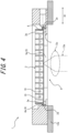
FIG. 4 is a B-B cross-sectional view ofFIG. 3 ; -
FIG. 5 is a top view illustrating a state in which a sample container holding device according to a comparative example improperly holds the sample container; and -
FIG. 6 is a block diagram of a sample analysis device with the sample container holding device illustrated inFIG. 1 . - An embodiment of the present disclosure will be exemplarily described below in detail with reference to the drawings.
- As illustrated in
FIGS. 1 to 4 , a samplecontainer holding device 1 according to the embodiment of the present disclosure is configured to hold asample container 2 in a rectangular shape (seeFIG. 3 ) with afirst side surface 2a, afirst corner 2b, asecond side surface 2c, asecond corner 2d, athird side surface 2e, athird corner 2f, afourth side surface 2g, and afourth corner 2h clockwise in this order in the top view. The samplecontainer holding device 1 includes amount 3 on which thesample container 2 is placed, afirst regulator 4 that regulates, by contact with thefirst side surface 2a, a position in a first horizontal direction D1 and a rotational position in the top view in thefirst side surface 2a, asecond regulator 5 that regulates, by contact with thesecond side surface 2c, a position in a second horizontal direction D2, which is orthogonal to the first horizontal direction D1, and the rotational position in the top view in thesecond side surface 2c, afirst press 6 that presses thefirst side surface 2a against thefirst regulator 4 by pushing thethird side surface 2e, and asecond press 7 that presses thesecond side surface 2c against thesecond regulator 5 by pushing thefourth side surface 2g. - According to the above configuration, pressing the
first side surface 2a against thefirst regulator 4, by pushing thethird side surface 2e by thefirst press 6, allows regulating the position in the first horizontal direction D1 and the rotational position in the top view in thefirst side surface 2a. Pressing thesecond side surface 2c against thesecond regulator 5, by pushing thefourth side surface 2g by thesecond press 7, allows regulating the position in the second horizontal direction D2 and the rotational position in the top view in thesecond side surface 2c. Therefore, when the positional regulation by thefirst press 6 is performed first, the press by thesecond press 7 is performed while the positional regulation by thefirst press 6 is performed, so thesample container 2 is less likely to be inclined when being pressed by thesecond press 7, which stably achieves positioning that determines the positions in the first horizontal direction D1 and the second horizontal direction D2 and the rotational position in the top view. When the positional regulation by thesecond press 7 is performed first, the press by thefirst press 6 is performed while the positional regulation by thesecond press 7 is performed, so thesample container 2 is less likely to be inclined when being pressed by thefirst press 6, which stably achieves positioning also in this case. Also in a case in which the positional regulation by thefirst press 6 and the positional regulation by thesecond press 7 are performed at the same time, positioning can be stably achieved. In contrast, as in a comparative example illustrated inFIG. 5 , the above effect may not be obtained in a configuration in which, although the samplecontainer holding device 1 has thefirst regulator 4 and thesecond regulator 5, the samplecontainer holding device 1 has acorner press 8 that presses thefirst side surface 2a and thesecond side surface 2c against thefirst regulator 4 and thesecond regulator 5 by pushing thethird corner 2f, instead of thefirst press 6, which presses thefirst side surface 2a against thefirst regulator 4 by pushing thethird side surface 2e, and thesecond press 7, which presses thesecond side surface 2c against thesecond regulator 5 by pushing thefourth side surface 2g. Thesample container 2 may be held in an inclined state, as illustrated inFIG. 5 , and fail in positioning. - Each of the
first press 6 and thesecond press 7 is configured with a linear motion device. According to the above configuration, the stability of positioning can be improved. The linear motion device may be constituted of, for example, a fluid pressure actuator using fluid pressure of air or the like, or an electric actuator using electricity. An operating direction (pressing direction) of the linear motion device that constitutes thefirst press 6 is preferably in parallel with the first horizontal direction D1, but is not limited to this. An operating direction (pressing direction) of the linear motion device that constitutes thesecond press 7 is preferably in parallel with the second horizontal direction D2, but is not limited to this. - The
first press 6 is located between both ends of thefirst regulator 4 in the second horizontal direction D2. Thesecond press 7 is located between both ends of thesecond regulator 5 in the first horizontal direction D1. According to the above configuration, the rotational position of thefirst side surface 2a can be easily regulated when thefirst press 6 presses thefirst side surface 2a against thefirst regulator 4, and the rotational position of thesecond side surface 2c can be easily regulated when thesecond press 7 presses thesecond side surface 2c against thesecond regulator 5, thus improving the stability of positioning. - The
first regulator 4 has areference plane 4a that contacts thefirst side surface 2a along the second horizontal direction D2. Thesecond regulator 5 has areference plane 5a that contacts thesecond side surface 2c along the first horizontal direction D1. According to the above configuration, thereference planes - The
mount 3 is configured with ashelf 3a that is located at each of four corners of anopening 9 that is open downward. According to the above configuration, it is possible to favorably analyzesamples 10, which are contained in thesample container 2 held by the samplecontainer holding device 1, using anoptical system 13a (seeFIG. 4 ) through theopening 9. - As illustrated in
FIG. 6 , asample analysis device 11 according to the present embodiment includes the samplecontainer holding device 1. According to the above configuration, the stable positioning by the samplecontainer holding device 1 can reduce noise during analysis of thesamples 10, thus improving the accuracy of output. In addition, the stable positioning by the samplecontainer holding device 1 can reduce the size of an analysis/observation area, thus improving the speed of output. Thesample analysis device 11 can be suitably used, for example, as a drug discovery support device. - The
sample analysis device 11 includes amover 12 that moves the samplecontainer holding device 1 that holds thesample container 2. According to the above configuration, accurate movement by stable positioning can be achieved in thesample analysis device 11. - The
sample analysis device 11 includes ananalyzer 13 that analyzes thesamples 10 contained in thesample container 2 by moving, by themover 12, the samplecontainer holding device 1 that holds thesample container 2. According to the above configuration, due to stable positioning, accurate analysis using themover 12 and theanalyzer 13 can be achieved. In addition to movement of thesample container 2 during analysis in theanalyzer 13, themover 12 may be configured to move the samplecontainer holding device 1 that holds thesample container 2, in order to carry thesample container 2 to theanalyzer 13. Themover 12 may also be configured to, without moving thesample container 2 during analysis in theanalyzer 13, move the samplecontainer holding device 1 that holds thesample container 2, in order to carry thesample container 2 to theanalyzer 13. - The
mover 12 has a movingstage 12a that can move the samplecontainer holding device 1, which holds thesample container 2, in parallel to the first horizontal direction D1, and the samplecontainer holding device 1, which holds thesample container 2, in parallel to the second horizontal direction D2. According to the above configuration, the samplecontainer holding device 1 during analysis in theanalyzer 13 can be accurately moved in the horizontal directions by the movingstage 12a. - The
mount 3 is configured with theshelf 3a that is located at each of the four corners of theopening 9 that is open downward. Theanalyzer 13 has theoptical system 13a that performs detection through theopening 9 for thesamples 10 contained in thesample container 2 held by the samplecontainer holding device 1. According to the above configuration, thesamples 10 can be analyzed favorably. In particular, during analysis in theanalyzer 13, due to accurate movement of thesample container 2 by themover 12 based on stable positioning, detection fields ofview 13b by theoptical system 13a can be stably aligned to proper positions in thesample container 2, as illustrated inFIG. 3 with the detection fields ofview 13b superimposed on thesample container 2. In contrast, in the comparative example illustrated inFIG. 5 , the detection fields ofview 13b are easily misaligned as illustrated in the drawing. - The
optical system 13a has amicroscope 13c. According to the above configuration, themicroscope 13c enables analysis with high accuracy. In this case, themover 12 can be configured to move the samplecontainer holding device 1 on the order of micrometers during analysis by themicroscope 13c. - The
samples 10 are, for example, cells, tissue, or the like. Thesample container 2 is a microplate, but is not limited to this. The microplate is not particularly limited, but preferably has external dimensions recommended in the SBS standard. Theoptical system 13a may be configured to apply light (e.g., excitation light) to thesamples 10 and detect light (e.g., light emitted by thesamples 10 excited by the excitation light) from thesamples 10. Thesample analysis device 11 may be configured with a processing unit (computer) that generates images based on the detection results by theoptical system 13a. Themover 12 moves the samplecontainer holding device 1 while keeping thesample container 2 in a horizontal posture, but is not limited to this. Thesample analysis device 11 may be configured with a robot arm that places thesample container 2 on the samplecontainer holding device 1, or may be configured that thesample container 2 is placed on the samplecontainer holding device 1 by a person. - Although the embodiment of the present disclosure has been described above, the present disclosure is not limited to the aforementioned embodiment. The aforementioned embodiment can be modified in various ways without departing from the gist of the present disclosure.
Claims (8)
- A sample container holding device configured to hold a sample container in a rectangular shape with a first side surface, a first corner, a second side surface, a second corner, a third side surface, a third corner, a fourth side surface, and a fourth corner clockwise in this order in top view, the sample container holding device comprising:a mount on which the sample container is placed;a first regulator configured to regulate, by contact with the first side surface, a position in a first horizontal direction and a rotational position in the top view in the first side surface;a second regulator configured to regulate, by contact with the second side surface, a position in a second horizontal direction and the rotational position in the top view in the second side surface, the second horizontal direction being orthogonal to the first horizontal direction;a first press configured to press the first side surface against the first regulator by pushing the third side surface; anda second press configured to press the second side surface against the second regulator by pushing the fourth side surface.
- The sample container holding device according to claim 1, wherein each of the first and second presses is configured with a linear motion device.
- The sample container holding device according to claim 1, whereinthe first press is located between both ends of the first regulator in the second horizontal direction, andthe second press is located between both ends of the second regulator in the first horizontal direction.
- The sample container holding device according to claim 1, whereinthe first regulator comprises a reference plane that contacts the first side surface along the second horizontal direction, andthe second regulator comprises a reference plane that contacts the second side surface along the first horizontal direction.
- The sample container holding device according to claim 1, wherein the mount is configured with a shelf that is located at each of four corners of an opening that is open downward.
- A sample analysis device comprising the sample container holding device according to claim 1.
- The sample analysis device according to claim 6, comprising a mover configured to move the sample container holding device that holds the sample container.
- The sample analysis device according to claim 7, comprising an analyzer configured to analyze a sample contained in the sample container by moving, by the mover, the sample container holding device that holds the sample container.
Applications Claiming Priority (1)
| Application Number | Priority Date | Filing Date | Title |
|---|---|---|---|
| JP2023184943A JP2025073835A (en) | 2023-10-27 | 2023-10-27 | Sample container holding device |
Publications (1)
| Publication Number | Publication Date |
|---|---|
| EP4545182A1 true EP4545182A1 (en) | 2025-04-30 |
Family
ID=93100910
Family Applications (1)
| Application Number | Title | Priority Date | Filing Date |
|---|---|---|---|
| EP24205715.6A Pending EP4545182A1 (en) | 2023-10-27 | 2024-10-10 | SAMPLE CONTAINER HOLDING DEVICE |
Country Status (4)
| Country | Link |
|---|---|
| US (1) | US20250137917A1 (en) |
| EP (1) | EP4545182A1 (en) |
| JP (1) | JP2025073835A (en) |
| CN (1) | CN119901934A (en) |
Citations (2)
| Publication number | Priority date | Publication date | Assignee | Title |
|---|---|---|---|---|
| WO2006078714A2 (en) * | 2005-01-19 | 2006-07-27 | Irm Llc | Multi-well container positioning devices, systems, computer program products, and methods |
| US20210016288A1 (en) * | 2019-07-16 | 2021-01-21 | Meso Scale Technologies, Llc. | Assay apparatuses, methods, and reagents |
-
2023
- 2023-10-27 JP JP2023184943A patent/JP2025073835A/en active Pending
-
2024
- 2024-09-23 CN CN202411325097.3A patent/CN119901934A/en active Pending
- 2024-10-10 EP EP24205715.6A patent/EP4545182A1/en active Pending
- 2024-10-18 US US18/919,524 patent/US20250137917A1/en active Pending
Patent Citations (2)
| Publication number | Priority date | Publication date | Assignee | Title |
|---|---|---|---|---|
| WO2006078714A2 (en) * | 2005-01-19 | 2006-07-27 | Irm Llc | Multi-well container positioning devices, systems, computer program products, and methods |
| US20210016288A1 (en) * | 2019-07-16 | 2021-01-21 | Meso Scale Technologies, Llc. | Assay apparatuses, methods, and reagents |
Also Published As
| Publication number | Publication date |
|---|---|
| JP2025073835A (en) | 2025-05-13 |
| CN119901934A (en) | 2025-04-29 |
| US20250137917A1 (en) | 2025-05-01 |
Similar Documents
| Publication | Publication Date | Title |
|---|---|---|
| EP2753968B1 (en) | Imaging systems, cassettes, and methods of using the same | |
| US10197586B2 (en) | Method of determining a handover position and laboratory automation system | |
| CN102313978B (en) | Stage system and microscope | |
| US8946652B2 (en) | Sample positioning apparatus, sample stage, and charged particle beam apparatus | |
| EP1865354A1 (en) | Microscopic image capturing device | |
| US20150160250A1 (en) | Device for gripping vessels | |
| JP2018525631A (en) | Autosampler sample and sample rack identification | |
| US20250137917A1 (en) | Sample container holding device | |
| JP2002318352A (en) | Holding member for positioning object carrier and device for laser cutting of specimen as well as microscope | |
| Enikov et al. | Microassembly experiments with transparent electrostatic gripper under optical and vision-based control | |
| US9633817B2 (en) | Diaphragm mounting member and charged particle beam device | |
| KR20170027000A (en) | Image analysis device included high speed and precision method | |
| TW200832605A (en) | Substrate fixing device and substrate fixing method | |
| US20220130652A1 (en) | Analysis method, analysis device, and program | |
| EP3026390A1 (en) | Interferometric biological measurement device and biological measurement method | |
| GB2635617A (en) | Device for desorption scanning of analyte material on a sample support | |
| EP3404694B1 (en) | Vacuum processing apparatus and mass spectrometer | |
| KR20240035793A (en) | Sample delivery, data collection and analysis, and automation in charged particle beam microscopy | |
| US12625054B2 (en) | Chip fixing device and particle inspection device | |
| CN115545209A (en) | Pin electrode alignment method for ion trap | |
| EP4545181A1 (en) | SAMPLE CONTAINER HOLDING DEVICE | |
| JP6234836B2 (en) | Substrate clamping mechanism, substrate fixing device, and substrate inspection device | |
| CN106769993A (en) | Sample compressing tablet bogey, terahertz light spectral measurement system and measuring method | |
| TWI697658B (en) | Complex inspection system of image | |
| CN217845937U (en) | Push-pull force testing device |
Legal Events
| Date | Code | Title | Description |
|---|---|---|---|
| PUAI | Public reference made under article 153(3) epc to a published international application that has entered the european phase |
Free format text: ORIGINAL CODE: 0009012 |
|
| STAA | Information on the status of an ep patent application or granted ep patent |
Free format text: STATUS: THE APPLICATION HAS BEEN PUBLISHED |
|
| AK | Designated contracting states |
Kind code of ref document: A1 Designated state(s): AL AT BE BG CH CY CZ DE DK EE ES FI FR GB GR HR HU IE IS IT LI LT LU LV MC ME MK MT NL NO PL PT RO RS SE SI SK SM TR |
|
| STAA | Information on the status of an ep patent application or granted ep patent |
Free format text: STATUS: REQUEST FOR EXAMINATION WAS MADE |
|
| 17P | Request for examination filed |
Effective date: 20251029 |