EP4543007A2 - Verfahren und vorrichtung für die videodekodierung, und verfahren und vorrichtung für die videokodierung - Google Patents
Verfahren und vorrichtung für die videodekodierung, und verfahren und vorrichtung für die videokodierung Download PDFInfo
- Publication number
- EP4543007A2 EP4543007A2 EP25162800.4A EP25162800A EP4543007A2 EP 4543007 A2 EP4543007 A2 EP 4543007A2 EP 25162800 A EP25162800 A EP 25162800A EP 4543007 A2 EP4543007 A2 EP 4543007A2
- Authority
- EP
- European Patent Office
- Prior art keywords
- coding unit
- reference line
- current block
- current
- split
- Prior art date
- Legal status (The legal status is an assumption and is not a legal conclusion. Google has not performed a legal analysis and makes no representation as to the accuracy of the status listed.)
- Pending
Links
Images


Classifications
-
- H—ELECTRICITY
- H04—ELECTRIC COMMUNICATION TECHNIQUE
- H04N—PICTORIAL COMMUNICATION, e.g. TELEVISION
- H04N19/00—Methods or arrangements for coding, decoding, compressing or decompressing digital video signals
- H04N19/10—Methods or arrangements for coding, decoding, compressing or decompressing digital video signals using adaptive coding
- H04N19/102—Methods or arrangements for coding, decoding, compressing or decompressing digital video signals using adaptive coding characterised by the element, parameter or selection affected or controlled by the adaptive coding
- H04N19/103—Selection of coding mode or of prediction mode
- H04N19/105—Selection of the reference unit for prediction within a chosen coding or prediction mode, e.g. adaptive choice of position and number of pixels used for prediction
-
- H—ELECTRICITY
- H04—ELECTRIC COMMUNICATION TECHNIQUE
- H04N—PICTORIAL COMMUNICATION, e.g. TELEVISION
- H04N19/00—Methods or arrangements for coding, decoding, compressing or decompressing digital video signals
- H04N19/10—Methods or arrangements for coding, decoding, compressing or decompressing digital video signals using adaptive coding
- H04N19/102—Methods or arrangements for coding, decoding, compressing or decompressing digital video signals using adaptive coding characterised by the element, parameter or selection affected or controlled by the adaptive coding
- H04N19/132—Sampling, masking or truncation of coding units, e.g. adaptive resampling, frame skipping, frame interpolation or high-frequency transform coefficient masking
-
- H—ELECTRICITY
- H04—ELECTRIC COMMUNICATION TECHNIQUE
- H04N—PICTORIAL COMMUNICATION, e.g. TELEVISION
- H04N19/00—Methods or arrangements for coding, decoding, compressing or decompressing digital video signals
- H04N19/10—Methods or arrangements for coding, decoding, compressing or decompressing digital video signals using adaptive coding
- H04N19/134—Methods or arrangements for coding, decoding, compressing or decompressing digital video signals using adaptive coding characterised by the element, parameter or criterion affecting or controlling the adaptive coding
- H04N19/136—Incoming video signal characteristics or properties
- H04N19/14—Coding unit complexity, e.g. amount of activity or edge presence estimation
-
- H—ELECTRICITY
- H04—ELECTRIC COMMUNICATION TECHNIQUE
- H04N—PICTORIAL COMMUNICATION, e.g. TELEVISION
- H04N19/00—Methods or arrangements for coding, decoding, compressing or decompressing digital video signals
- H04N19/10—Methods or arrangements for coding, decoding, compressing or decompressing digital video signals using adaptive coding
- H04N19/169—Methods or arrangements for coding, decoding, compressing or decompressing digital video signals using adaptive coding characterised by the coding unit, i.e. the structural portion or semantic portion of the video signal being the object or the subject of the adaptive coding
- H04N19/17—Methods or arrangements for coding, decoding, compressing or decompressing digital video signals using adaptive coding characterised by the coding unit, i.e. the structural portion or semantic portion of the video signal being the object or the subject of the adaptive coding the unit being an image region, e.g. an object
- H04N19/176—Methods or arrangements for coding, decoding, compressing or decompressing digital video signals using adaptive coding characterised by the coding unit, i.e. the structural portion or semantic portion of the video signal being the object or the subject of the adaptive coding the unit being an image region, e.g. an object the region being a block, e.g. a macroblock
-
- H—ELECTRICITY
- H04—ELECTRIC COMMUNICATION TECHNIQUE
- H04N—PICTORIAL COMMUNICATION, e.g. TELEVISION
- H04N19/00—Methods or arrangements for coding, decoding, compressing or decompressing digital video signals
- H04N19/10—Methods or arrangements for coding, decoding, compressing or decompressing digital video signals using adaptive coding
- H04N19/169—Methods or arrangements for coding, decoding, compressing or decompressing digital video signals using adaptive coding characterised by the coding unit, i.e. the structural portion or semantic portion of the video signal being the object or the subject of the adaptive coding
- H04N19/186—Methods or arrangements for coding, decoding, compressing or decompressing digital video signals using adaptive coding characterised by the coding unit, i.e. the structural portion or semantic portion of the video signal being the object or the subject of the adaptive coding the unit being a colour or a chrominance component
-
- H—ELECTRICITY
- H04—ELECTRIC COMMUNICATION TECHNIQUE
- H04N—PICTORIAL COMMUNICATION, e.g. TELEVISION
- H04N19/00—Methods or arrangements for coding, decoding, compressing or decompressing digital video signals
- H04N19/10—Methods or arrangements for coding, decoding, compressing or decompressing digital video signals using adaptive coding
- H04N19/189—Methods or arrangements for coding, decoding, compressing or decompressing digital video signals using adaptive coding characterised by the adaptation method, adaptation tool or adaptation type used for the adaptive coding
- H04N19/196—Methods or arrangements for coding, decoding, compressing or decompressing digital video signals using adaptive coding characterised by the adaptation method, adaptation tool or adaptation type used for the adaptive coding being specially adapted for the computation of encoding parameters, e.g. by averaging previously computed encoding parameters
-
- H—ELECTRICITY
- H04—ELECTRIC COMMUNICATION TECHNIQUE
- H04N—PICTORIAL COMMUNICATION, e.g. TELEVISION
- H04N19/00—Methods or arrangements for coding, decoding, compressing or decompressing digital video signals
- H04N19/42—Methods or arrangements for coding, decoding, compressing or decompressing digital video signals characterised by implementation details or hardware specially adapted for video compression or decompression, e.g. dedicated software implementation
- H04N19/423—Methods or arrangements for coding, decoding, compressing or decompressing digital video signals characterised by implementation details or hardware specially adapted for video compression or decompression, e.g. dedicated software implementation characterised by memory arrangements
- H04N19/426—Methods or arrangements for coding, decoding, compressing or decompressing digital video signals characterised by implementation details or hardware specially adapted for video compression or decompression, e.g. dedicated software implementation characterised by memory arrangements using memory downsizing methods
-
- H—ELECTRICITY
- H04—ELECTRIC COMMUNICATION TECHNIQUE
- H04N—PICTORIAL COMMUNICATION, e.g. TELEVISION
- H04N19/00—Methods or arrangements for coding, decoding, compressing or decompressing digital video signals
- H04N19/50—Methods or arrangements for coding, decoding, compressing or decompressing digital video signals using predictive coding
- H04N19/593—Methods or arrangements for coding, decoding, compressing or decompressing digital video signals using predictive coding involving spatial prediction techniques
-
- H—ELECTRICITY
- H04—ELECTRIC COMMUNICATION TECHNIQUE
- H04N—PICTORIAL COMMUNICATION, e.g. TELEVISION
- H04N19/00—Methods or arrangements for coding, decoding, compressing or decompressing digital video signals
- H04N19/90—Methods or arrangements for coding, decoding, compressing or decompressing digital video signals using coding techniques not provided for in groups H04N19/10-H04N19/85, e.g. fractals
- H04N19/96—Tree coding, e.g. quad-tree coding
-
- H—ELECTRICITY
- H04—ELECTRIC COMMUNICATION TECHNIQUE
- H04N—PICTORIAL COMMUNICATION, e.g. TELEVISION
- H04N19/00—Methods or arrangements for coding, decoding, compressing or decompressing digital video signals
- H04N19/10—Methods or arrangements for coding, decoding, compressing or decompressing digital video signals using adaptive coding
- H04N19/102—Methods or arrangements for coding, decoding, compressing or decompressing digital video signals using adaptive coding characterised by the element, parameter or selection affected or controlled by the adaptive coding
- H04N19/119—Adaptive subdivision aspects, e.g. subdivision of a picture into rectangular or non-rectangular coding blocks
-
- H—ELECTRICITY
- H04—ELECTRIC COMMUNICATION TECHNIQUE
- H04N—PICTORIAL COMMUNICATION, e.g. TELEVISION
- H04N19/00—Methods or arrangements for coding, decoding, compressing or decompressing digital video signals
- H04N19/10—Methods or arrangements for coding, decoding, compressing or decompressing digital video signals using adaptive coding
- H04N19/102—Methods or arrangements for coding, decoding, compressing or decompressing digital video signals using adaptive coding characterised by the element, parameter or selection affected or controlled by the adaptive coding
- H04N19/129—Scanning of coding units, e.g. zig-zag scan of transform coefficients or flexible macroblock ordering [FMO]
-
- H—ELECTRICITY
- H04—ELECTRIC COMMUNICATION TECHNIQUE
- H04N—PICTORIAL COMMUNICATION, e.g. TELEVISION
- H04N19/00—Methods or arrangements for coding, decoding, compressing or decompressing digital video signals
- H04N19/70—Methods or arrangements for coding, decoding, compressing or decompressing digital video signals characterised by syntax aspects related to video coding, e.g. related to compression standards
Definitions
- a video decoding apparatus includes: a memory; and at least one processor connected to the memory, wherein the at least one processor is configured to: determine whether a current block is in contact with an upper boundary of a largest coding unit including the current block; when it is determined that the current block is in contact with the upper boundary of the largest coding unit, determine an upper reference line of the current block as one reference line; when it is determined that the current block is not in contact with the upper boundary of the largest coding unit, determine the upper reference line of the current block based on N reference lines; and perform prediction on the current block, based on the determined upper reference line, wherein N is a natural number.
- a video encoding method includes: determining whether a current block is in contact with an upper boundary of a largest coding unit including the current block; when it is determined that the current block is in contact with the upper boundary of the largest coding unit, determining an upper reference line of the current block as one reference line; when it is determined that the current block is not in contact with the upper boundary of the largest coding unit, determining the upper reference line of the current block based on N reference lines; and performing prediction on the current block, wherein N is a natural number.
- a video encoding apparatus includes at least one processor connected to a memory, wherein the at least one processor is configured to: determine whether a current block is in contact with an upper boundary of a largest coding unit including the current block; when it is determined that the current block is in contact with the upper boundary of the largest coding unit, determine an upper reference line of the current block as one reference line; when it is determined that the current block is not in contact with the upper boundary of the largest coding unit, determine the upper reference line of the current block based on N reference lines; and perform prediction on the current block, based on the determined upper reference line, wherein N is a natural number.
- a current block is in contact with an upper boundary of a largest coding unit including the current block is determined, when it is determined to be in contact with the upper boundary, an upper reference line of the current block is determined as one reference line, when it is determined not to be in contact with the upper boundary, the upper reference line of the current block is determined based on N reference lines, and the determined upper reference line is used, such that the size of a buffer generated when a plurality of reference lines are used may be reduced.
- a video decoding method includes: determining whether a current block is in contact with an upper boundary of a largest coding unit including the current block; when it is determined that the current block is in contact with the upper boundary of the largest coding unit, determining an upper reference line of the current block as one reference line; when it is determined that the current block is not in contact with the upper boundary of the largest coding unit, determining the upper reference line of the current block based on N reference lines; and based on the determined upper reference line, performing prediction on the current block, wherein N is a natural number.
- N may be determined according to reference line information obtained from a bitstream.
- the reference line information when it is determined that the current block is in contact with the upper boundary of the largest coding unit, the reference line information may not be obtained.
- the upper reference line when N is 2, the upper reference line may be determined as a second reference line in contact with an upper side of a first reference line in contact with an upper side of the current block.
- the upper reference line may be determined as a fourth reference line in contact with an upper side of a third reference line in contact with an upper side of a second reference line in contact with an upper side of a first reference line in contact with an upper side of the current block.
- a left reference line located in a left side of the current block is determined based on the N reference lines.
- a sample value of the reference line having no sample value may be padded by using a predetermined default value.
- a value of a reference sample having no sample value may be padded with a reference sample having sample value, or a sample of the reference line having no sample value may be regenerated by using a sample value of a reference line having a sample value.
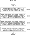
- a video decoding method includes: determining whether a current luma block is in contact with an upper boundary of a largest coding unit including the current luma block; when it is determined that the current luma block is in contact with the upper boundary of the largest coding unit, determining an upper reference line of the current luma block as one reference line; when it is determined that the current luma block is not in contact with the upper boundary of the largest coding unit, determining the upper reference line of the current luma block as two reference lines; and based on the determined upper reference line, performing prediction on a current chroma block corresponding to the current luma block.
- the two reference lines may include a first reference line in contact with an upper side of the current luma block and a second reference line in contact with an upper side of the first reference line.
- weight information and deviation information may be determined based on a relationship between luma reference samples of the current luma block included in the upper reference line and a chroma reference sample in contact with an upper side of the current chroma block, and by determining the current chroma block based on the weight information, the deviation information, and luma samples of the current luma block, prediction may be performed on the current chroma block.
- a video encoding method includes: determining whether a current block is in contact with an upper boundary of a largest coding unit including the current block; when it is determined that the current block is in contact with the upper boundary of the largest coding unit, determining an upper reference line of the current block as one reference line; when it is determined that the current block is not in contact with the upper boundary of the largest coding unit, determining the upper reference line of the current block based on N reference lines; and based on the determined upper reference line, performing prediction on the current block, wherein N is a natural number.
- the coding unit may be smaller than or the same as the largest coding unit.
- a largest coding unit is a coding unit having a maximum size
- the largest coding unit is one of coding units.
- split shape mode information about a largest coding unit indicates that splitting is not performed
- a coding unit determined in the largest coding unit has the same size as that of the largest coding unit.
- split shape mode information about a largest coding unit indicates that splitting is performed
- the largest coding unit may be split into coding units.
- the coding unit may be split into smaller coding units.
- the splitting of the image is not limited thereto, and the largest coding unit and the coding unit may not be distinguished. The splitting of the coding unit will be described in detail with reference to FIGS. 3 through 16 .
- the image decoding apparatus 100 may obtain the split shape mode information, and may obtain a plurality of various-shaped second coding units (e.g., 510) by splitting the first coding unit 500, based on the obtained split shape mode information, and the second coding unit 510 may be split by using a splitting method of the first coding unit 500 based on the split shape mode information.
- the second coding unit 510 may also be split into the third coding units (e.g., 520a, or 520b, 520c, and 520d) based on the split shape mode information of the second coding unit 510.
- the image decoding apparatus 100 may use the split shape mode information to determine a coding unit at a preset location from among the plurality of coding units.
- the image decoding apparatus 100 may obtain the split shape mode information from a sample at a preset location in a coding unit, and split the plurality of coding units, which are generated by splitting the current coding unit, by using the split shape mode information, which is obtained from the sample of the preset location in each of the plurality of coding units. That is, a coding unit may be recursively split based on the split shape mode information, which is obtained from the sample at the preset location in each coding unit. An operation of recursively splitting a coding unit has been described above in relation to FIG. 5 , and thus detailed descriptions thereof will not be provided here.
- the image decoding apparatus 100 may determine one or more coding units by splitting the current coding unit, and may determine an order of decoding the one or more coding units, based on a preset block (e.g., the current coding unit).
- a preset block e.g., the current coding unit
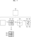
- FIG. 7 illustrates an order of processing a plurality of coding units when an image decoding apparatus determines the plurality of coding units by splitting a current coding unit, according to an embodiment.
- the image decoding apparatus 100 may determine second coding units 710a and 710b by splitting a first coding unit 700 in a vertical direction, determine second coding units 730a and 730b by splitting the first coding unit 700 in a horizontal direction, or determine second coding units 750a to 750d by splitting the first coding unit 700 in vertical and horizontal directions, based on split shape mode information.
- the image decoding apparatus 100 may determine to process the second coding units 710a and 710b, which are determined by splitting the first coding unit 700 in a vertical direction, in a horizontal direction order 710c.
- the image decoding apparatus 100 may determine to process the second coding units 730a and 730b, which are determined by splitting the first coding unit 700 in a horizontal direction, in a vertical direction order 730c.
- the image decoding apparatus 100 may determine the second coding units 750a to 750d, which are determined by splitting the first coding unit 700 in vertical and horizontal directions, according to a preset order (e.g., a raster scan order or Z-scan order 750e) by which coding units in a row are processed and then coding units in a next row are processed.
- a preset order e.g., a raster scan order or Z-scan order 750e
- the image decoding apparatus 100 may recursively split coding units.
- the image decoding apparatus 100 may determine the plurality of coding units 710a and 710b, 730a and 730b, or 750a to 750d by splitting the first coding unit 700, and recursively split each of the determined plurality of coding units 710a, 710b, 730a, 730b, 750a, 750b, 750c, and 750d.
- a splitting method of the plurality of coding units 710a and 710b, 730a and 730b, or 750a to 750d may correspond to a splitting method of the first coding unit 700.
- each of the plurality of coding units 710a and 710b, 730a and 730b, or 750a to 750d may be independently split into a plurality of coding units.
- the image decoding apparatus 100 may determine the second coding units 710a and 710b by splitting the first coding unit 700 in a vertical direction, and may determine to independently split or not to split each of the second coding units 710a and 710b.
- the image decoding apparatus 100 may determine third coding units 720a and 720b by splitting the left second coding unit 710a in a horizontal direction, and may not split the right second coding unit 710b.
- a processing order of coding units may be determined based on an operation of splitting a coding unit.
- a processing order of split coding units may be determined based on a processing order of coding units immediately before being split.
- the image decoding apparatus 100 may determine a processing order of the third coding units 720a and 720b determined by splitting the left second coding unit 710a, independently of the right second coding unit 710b. Because the third coding units 720a and 720b are determined by splitting the left second coding unit 710a in a horizontal direction, the third coding units 720a and 720b may be processed in a vertical direction order 720c.
- the right second coding unit 710b may be processed after the third coding units 720a and 720b included in the left second coding unit 710a are processed in the vertical direction order 720c.
- An operation of determining a processing order of coding units based on a coding unit before being split is not limited to the above-described example, and various methods may be used to independently process coding units, which are split and determined to various shapes, in a preset order.
- FIG. 8 illustrates a process, performed by an image decoding apparatus, of determining that a current coding unit is to be split into an odd number of coding units, when the coding units are not processable in a preset order, according to an embodiment.
- the image decoding apparatus 100 may determine that the current coding unit is split into an odd number of coding units, based on obtained split shape mode information.
- a square first coding unit 800 may be split into non-square second coding units 810a and 810b, and the second coding units 810a and 810b may be independently split into third coding units 820a and 820b, and 820c to 820e.
- the image decoding apparatus 100 may determine the plurality of third coding units 820a and 820b by splitting the left second coding unit 810a in a horizontal direction, and may split the right second coding unit 810b into the odd number of third coding units 820c to 820e.
- the video decoding apparatus 100 may determine whether any coding unit is split into an odd number of coding units, by determining whether the third coding units 820a and 820b, and 820c to 820e are processable in a preset order. Referring to FIG. 8 , the image decoding apparatus 100 may determine the third coding units 820a and 820b, and 820c to 820e by recursively splitting the first coding unit 800.
- the image decoding apparatus 100 may determine whether any of the first coding unit 800, the second coding units 810a and 810b, or the third coding units 820a and 820b, and 820c to 820e are split into an odd number of coding units, based on at least one of the block shape information and the split shape mode information. For example, a coding unit located in the right from among the second coding units 810a and 810b may be split into an odd number of third coding units 820c, 820d, and 820e.
- a processing order of a plurality of coding units included in the first coding unit 800 may be a preset order (e.g., a Z-scan order 830), and the image decoding apparatus 100 may determine whether the third coding units 820c, 820d, and 820e, which are determined by splitting the right second coding unit 810b into an odd number of coding units, satisfy a condition for processing in the preset order.
- a preset order e.g., a Z-scan order 830
- the image decoding apparatus 100 may determine whether the third coding units 820a and 820b, and 820c to 820e included in the first coding unit 800 satisfy the condition for processing in the preset order, and the condition relates to whether at least one of a width and height of the second coding units 810a and 810b is to be split in half along a boundary of the third coding units 820a and 820b, and 820c to 820e.
- the third coding units 820a and 820b determined when the height of the left second coding unit 810a of the non-square shape is split in half may satisfy the condition.
- the image decoding apparatus 100 may determine disconnection of a scan order, and may determine that the right second coding unit 810b is to be split into an odd number of coding units, based on a result of the determination.
- the image decoding apparatus 100 may put a preset restriction on a coding unit at a preset location from among the split coding units.
- the restriction or the preset location has been described above in relation to various embodiments, and thus detailed descriptions thereof will not be provided herein.
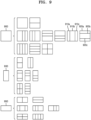
- FIG. 9 illustrates a process, performed by an image decoding apparatus, of determining at least one coding unit by splitting a first coding unit, according to an embodiment.
- the image decoding apparatus 100 may split the first coding unit 900, based on split shape mode information, which is obtained through the receiver 110.
- the square first coding unit 900 may be split into four square coding units, or may be split into a plurality of non-square coding units.
- the image decoding apparatus 100 may split the first coding unit 900 into a plurality of non-square coding units.
- the image decoding apparatus 100 may split the square first coding unit 900 into an odd number of coding units, e.g., second coding units 910a, 910b, and 910c determined by splitting the square first coding unit 900 in a vertical direction or second coding units 920a, 920b, and 920c determined by splitting the square first coding unit 900 in a horizontal direction.
- odd number of coding units e.g., second coding units 910a, 910b, and 910c determined by splitting the square first coding unit 900 in a vertical direction or second coding units 920a, 920b, and 920c determined by splitting the square first coding unit 900 in a horizontal direction.
- the image decoding apparatus 100 may determine whether the second coding units 910a, 910b, 910c, 920a, 920b, and 920c included in the first coding unit 900 satisfy a condition for processing in a preset order, and the condition relates to whether at least one of a width and height of the first coding unit 900 is to be split in half along a boundary of the second coding units 910a, 910b, 910c, 920a, 920b, and 920c. Referring to FIG.
- the image decoding apparatus 100 may decide disconnection of a scan order, and may determine that the first coding unit 900 is to be split into an odd number of coding units, based on a result of the decision. According to an embodiment, when a coding unit is split into an odd number of coding units, the image decoding apparatus 100 may put a preset restriction on a coding unit at a preset location from among the split coding units.
- the restriction or the preset location has been described above in relation to various embodiments, and thus detailed descriptions thereof will not be provided herein.
- the image decoding apparatus 100 may determine various-shaped coding units by splitting a first coding unit.
- the image decoding apparatus 100 may split the square first coding unit 900 or a non-square first coding unit 930 or 950 into various-shaped coding units.
- FIG. 10 illustrates that a shape into which a second coding unit is splittable is restricted when the second coding unit having a non-square shape, which is determined when an image decoding apparatus splits a first coding unit, satisfies a preset condition, according to an embodiment.
- the image decoding apparatus 100 may determine to split the square first coding unit 1000 into non-square second coding units 1010a, and1010b or 1020a and 1020b, based on split shape mode information, which is obtained by the receiver 110.
- the second coding units 1010a and 1010b, or 1020a and 1020b may be independently split.
- the image decoding apparatus 100 may determine to split or not to split each of the second coding units 1010a and 1010b, or 1020a and 1020b into a plurality of coding units, based on the split shape mode information of each of the second coding units 1010a and 1010b, or 1020a and 1020b.
- the image decoding apparatus 100 may determine third coding units 1012a and 1012b by splitting the non-square left second coding unit 1010a, which is determined by splitting the first coding unit 1000 in a vertical direction, in a horizontal direction. However, when the left second coding unit 1010a is split in a horizontal direction, the image decoding apparatus 100 may restrict the right second coding unit 1010b to not be split in a horizontal direction in which the left second coding unit 1010a is split.
- third coding units 1014a and 1014b are determined by splitting the right second coding unit 1010b in a same direction, because the left and right second coding units 1010a and 1010b are independently split in a horizontal direction, the third coding units 1012a and 1012b, or 1014a and 1014b may be determined.
- this case serves equally as a case in which the image decoding apparatus 100 splits the first coding unit 1000 into four square second coding units 1030a, 1030b, 1030c, and 1030d, based on the split shape mode information, and may be inefficient in terms of image decoding.
- the image decoding apparatus 100 may determine third coding units 1022a and 1022b, or 1024a and 1024b by splitting the non-square second coding unit 1020a or 1020b, which is determined by splitting the first coding unit 1000 in a horizontal direction, in a vertical direction.
- a second coding unit e.g., the upper second coding unit 1020a
- the image decoding apparatus 100 may restrict the other second coding unit (e.g., the lower second coding unit 1020b) to not be split in a vertical direction in which the upper second coding unit 1020a is split.
- FIG. 11 illustrates a process, performed by an image decoding apparatus, of splitting a square coding unit when split shape mode information indicates that the square coding unit is not to be split into four square coding units, according to an embodiment.
- the image decoding apparatus 100 may independently split the non-square second coding units 1110a and 1110b, or 1120a and 1120b, etc.
- Each of the second coding units 1110a and 1110b, or 1120a and 1120b, etc. may be recursively split in a preset order, and this splitting method may correspond to a method of splitting the first coding unit 1100, based on the split shape mode information.
- the image decoding apparatus 100 may determine square third coding units 1122a and 1122b by splitting the upper second coding unit 1120a in a vertical direction, and may determine square third coding units 1124a and 1124b by splitting the lower second coding unit 1120b in a vertical direction. Furthermore, the image decoding apparatus 100 may determine square third coding units 1126a, 1126b, 1126c, and 1126d by splitting both of the upper and lower second coding units 1120a and 1120b in a vertical direction. In this case, coding units having the same shape as the four square second coding units 1130a, 1130b, 1130c, and 1130d split from the first coding unit 1100 may be determined.
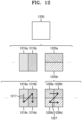
- the image decoding apparatus 100 may determine third coding units 1216a, 1216b, 1216c, and 1216d by splitting the second coding units 1210a and 1210b, which are generated by splitting the first coding unit 1200 in a vertical direction, in a horizontal direction, and may determine third coding units 1226a, 1226b, 1226c, and 1226d by splitting the second coding units 1220a and 1220b, which are generated by splitting the first coding unit 1200 in a horizontal direction, in a vertical direction.
- An operation of splitting the second coding units 1210a and 1210b, or 1220a and 1220b has been described above in relation to FIG. 11 , and thus detailed descriptions thereof will not be provided herein.
- the image decoding apparatus 100 may process coding units in a preset order. An operation of processing coding units in a preset order has been described above in relation to FIG. 7 , and thus detailed descriptions thereof will not be provided herein. Referring to FIG. 12 , the image decoding apparatus 100 may determine four square third coding units 1216a, 1216b, 1216c, and 1216d, and 1226a, 1226b, 1226c, and 1226d by splitting the square first coding unit 1200.
- the image decoding apparatus 100 may determine processing orders of the third coding units 1216a, 1216b, 1216c, and 1216d, and 1226a, 1226b, 1226c, and 1226d based on a split shape by which the first coding unit 1200 is split.
- the image decoding apparatus 100 may determine the third coding units 1216a, 1216b, 1216c, and 1216d by splitting the second coding units 1210a and 1210b generated by splitting the first coding unit 1200 in a vertical direction, in a horizontal direction, and may process the third coding units 1216a, 1216b, 1216c, and 1216d in a processing order 1217 for initially processing the third coding units 1216a and 1216c, which are included in the left second coding unit 1210a, in a vertical direction and then processing the third coding unit 1216b and 1216d, which are included in the right second coding unit 1210b, in a vertical direction.
- the image decoding apparatus 100 may determine the third coding units 1226a, 1226b, 1226c, and 1226d by splitting the second coding units 1220a and 1220b generated by splitting the first coding unit 1200 in a horizontal direction, in a vertical direction, and may process the third coding units 1226a, 1226b, 1226c, and 1226d in a processing order 1227 for initially processing the third coding units 1226a and 1226b, which are included in the upper second coding unit 1220a, in a horizontal direction and then processing the third coding unit 1226c and 1226d, which are included in the lower second coding unit 1220b, in a horizontal direction.
- the square third coding units 1216a, 1216b, 1216c, and 1216d, and 1226a, 1226b, 1226c, and 1226d may be determined by splitting the second coding units 1210a and 1210b, and 1220a and 1220b, respectively.
- the second coding units 1210a and 1210b are determined by splitting the first coding unit 1200 in a vertical direction differently from the second coding units 1220a and 1220b which are determined by splitting the first coding unit 1200 in a horizontal direction
- the third coding units 1216a, 1216b, 1216c, and 1216d, and 1226a, 1226b, 1226c, and 1226d split therefrom eventually show same-shaped coding units split from the first coding unit 1200.
- the image decoding apparatus 100 may process a plurality of coding units in different orders even when the coding units are eventually determined to be the same shape.
- FIG. 13 illustrates a process of determining a depth of a coding unit as a shape and size of the coding unit change, when the coding unit is recursively split such that a plurality of coding units are determined, according to an embodiment.
- the image decoding apparatus 100 may determine the depth of the coding unit, based on a preset criterion.
- the preset criterion may be the length of a long side of the coding unit.
- the image decoding apparatus 100 may determine that a depth of the current coding unit is increased from a depth of the coding unit before being split, by n.
- a coding unit having an increased depth is expressed as a coding unit of a deeper depth.
- the image decoding apparatus 100 may determine a second coding unit 1302 and a third coding unit 1304 of deeper depths by splitting a square first coding unit 1300 based on block shape information indicating a square shape (e.g., the block shape information may be expressed as '0: SQUARE'). Assuming that the size of the square first coding unit 1300 is 2N ⁇ 2N, the second coding unit 1302 determined by splitting a width and height of the first coding unit 1300 in 1/2 may have a size of N ⁇ N. Furthermore, the third coding unit 1304 determined by splitting a width and height of the second coding unit 1302 in 1/2 may have a size of N/2 ⁇ N/2.
- a width and height of the third coding unit 1304 are 1/4 times those of the first coding unit 1300.
- a depth of the first coding unit 1300 is D
- a depth of the second coding unit 1302 the width and height of which are 1/2 times those of the first coding unit 1300, may be D+1
- the image decoding apparatus 100 may determine a second coding unit 1312 or 1322 and a third coding unit 1314 or 1324 of deeper depths by splitting a non-square first coding unit 1310 or 1320 based on block shape information indicating a non-square shape (e.g., the block shape information may be expressed as '1: NS_VER' indicating a non-square shape, a height of which is longer than a width, or as '2: NS_HOR' indicating a non-square shape, a width of which is longer than a height).
- block shape information may be expressed as '1: NS_VER' indicating a non-square shape, a height of which is longer than a width, or as '2: NS_HOR' indicating a non-square shape, a width of which is longer than a height).
- the image decoding apparatus 100 may determine the second coding unit 1302, 1312, or 1322 by splitting at least one of a width and height of the first coding unit 1320 having a size of 2N ⁇ N. That is, the image decoding apparatus 100 may determine the second coding unit 1302 having a size of N ⁇ N or the second coding unit 1312 having a size of N/2 ⁇ N by splitting the first coding unit 1320 in a vertical direction, or may determine the second coding unit 1322 having a size of N ⁇ N/2 by splitting the first coding unit 1320 in horizontal and vertical directions.
- the image decoding apparatus 100 may determine a third coding unit 1304, 1314, or 1324 by splitting at least one of a width and height of the second coding unit 1302 having a size of N ⁇ N. That is, the image decoding apparatus 100 may determine the third coding unit 1304 having a size of N/2 ⁇ N/2, the third coding unit 1314 having a size of N/4 ⁇ N/2, or the third coding unit 1324 having a size of N/2 ⁇ N/4 by splitting the second coding unit 1302 in vertical and horizontal directions.
- the image decoding apparatus 100 may determine the third coding unit 1304, 1314, or 1324 by splitting at least one of a width and height of the second coding unit 1312 having a size of N/2 ⁇ N. That is, the image decoding apparatus 100 may determine the third coding unit 1304 having a size of N/2 ⁇ N/2 or the third coding unit 1324 having a size of N/2 ⁇ N/4 by splitting the second coding unit 1312 in a horizontal direction, or may determine the third coding unit 1314 having a size of N/4 ⁇ N/2 by splitting the second coding unit 1312 in vertical and horizontal directions.
- the image decoding apparatus 100 may determine the third coding unit 1304, 1314, or 1324 by splitting at least one of a width and height of the second coding unit 1322 having a size of N ⁇ N/2. That is, the image decoding apparatus 100 may determine the third coding unit 1304 having a size of N/2 ⁇ N/2 or the third coding unit 1314 having a size of N/4 ⁇ N/2 by splitting the second coding unit 1322 in a vertical direction, or may determine the third coding unit 1324 having a size of N/2 ⁇ N/4 by splitting the second coding unit 1322 in vertical and horizontal directions.
- the image decoding apparatus 100 may split the square coding unit 1300, 1302, or 1304 in a horizontal or vertical direction. For example, the image decoding apparatus 100 may determine the first coding unit 1310 having a size of N ⁇ 2N by splitting the first coding unit 1300 having a size of 2N ⁇ 2N in a vertical direction, or may determine the first coding unit 1320 having a size of 2N ⁇ N by splitting the first coding unit 1300 in a horizontal direction.
- a depth of a coding unit determined by splitting the first coding unit 1300 having a size of 2N ⁇ 2N in a horizontal or vertical direction may be the same as the depth of the first coding unit 1300.
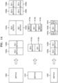
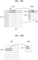
- FIG. 14 illustrates depths that are determinable based on shapes and sizes of coding units, and part indexes (PIDs) that are for distinguishing the coding units, according to an embodiment.
- the image decoding apparatus 100 may determine various-shape second coding units by splitting a square first coding unit 1400.
- the image decoding apparatus 100 may determine second coding units 1402a and 1402b, 1404a and 1404b, and 1406a, 1406b, 1406c, and 1406d by splitting the first coding unit 1400 in at least one of vertical and horizontal directions based on split shape mode information. That is, the image decoding apparatus 100 may determine the second coding units 1402a and 1402b, 1404a and 1404b, and 1406a, 1406b, 1406c, and 1406d, based on the split shape mode information of the first coding unit 1400.
- depths of the second coding units 1402a and 1402b, 1404a and 1404b, and 1406a, 1406b, 1406c, and 1406d that are determined based on the split shape mode information of the square first coding unit 1400 may be determined based on the length of a long side thereof. For example, because the length of a side of the square first coding unit 1400 equals the length of a long side of the non-square second coding units 1402a and 1402b, and 1404a and 1404b, the first coding unit 1400 and the non-square second coding units 1402a and 1402b, and 1404a and 1404b may have the same depth, e.g., D.
- a depth of the second coding units 1406a, 1406b, 1406c, and 1406d may be D+1 which is deeper than the depth D of the first coding unit 1400 by 1.
- the image decoding apparatus 100 may determine a plurality of second coding units 1412a and 1412b, and 1414a, 1414b, and 1414c by splitting a first coding unit 1410, a height of which is longer than a width, in a horizontal direction based on the split shape mode information. According to an embodiment, the image decoding apparatus 100 may determine a plurality of second coding units 1422a and 1422b, and 1424a, 1424b, and 1424c by splitting a first coding unit 1420, a width of which is longer than a height, in a vertical direction based on the split shape mode information.
- a depth of the square second coding units 1412a and 1412b is D+1 which is deeper than the depth D of the non-square first coding unit 1410 by 1.
- the image decoding apparatus 100 may split the non-square first coding unit 1410 into an odd number of second coding units 1414a, 1414b, and 1414c based on the split shape mode information.
- the odd number of second coding units 1414a, 1414b, and 1414c may include the non-square second coding units 1414a and 1414c and the square second coding unit 1414b.
- a depth of the second coding units 1414a, 1414b, and 1414c may be D+1 which is deeper than the depth D of the non-square first coding unit 1410 by 1.
- the image decoding apparatus 100 may determine depths of coding units split from the first coding unit 1420 having a non-square shape, a width of which is longer than a height, by using the above-described method of determining depths of coding units split from the first coding unit 1410.
- a PID of the coding unit 1414b at the center location is 1 based on a scan order
- a PID of the coding unit 1414c located next to the coding unit 1414b may be increased by 2 and thus may be 3. That is, discontinuity in PID values may be present.
- the image decoding apparatus 100 may determine whether an odd number of split coding units do not have equal sizes, based on whether discontinuity is present in PIDs for identifying the split coding units.
- the image decoding apparatus 100 may determine a coding unit at a preset location from among the split coding units, by using the PIDs for distinguishing the coding units.
- the image decoding apparatus 100 may split the first coding unit 1410 into three coding units 1414a, 1414b, and 1414c.
- the image decoding apparatus 100 may assign a PID to each of the three coding units 1414a, 1414b, and 1414c.
- the image decoding apparatus 100 may compare PIDs of an odd number of split coding units to determine a coding unit at a center location from among the coding units.
- the image decoding apparatus 100 may determine the coding unit 1414b having a PID corresponding to a middle value among the PIDs of the coding units, as the coding unit at the center location from among the coding units determined by splitting the first coding unit 1410.
- the image decoding apparatus 100 may determine PIDs for distinguishing split coding units, based on a size ratio between the coding units when the split coding units do not have equal sizes. Referring to FIG.
- the coding unit 1414b generated by splitting the first coding unit 1410 may have a width equal to that of the other coding units 1414a and 1414c and a height which is two times that of the other coding units 1414a and 1414c.
- the PID of the coding unit 1414b at the center location is 1, the PID of the coding unit 1414c located next to the coding unit 1414b may be increased by 2 and thus may be 3.
- the image decoding apparatus 100 may determine that a coding unit is split into a plurality of coding units including a coding unit having a size different from that of the other coding units.
- the image decoding apparatus 100 may split a current coding unit in such a manner that a coding unit of a preset location among an odd number of coding units (e.g., a coding unit of a center location) has a size different from that of the other coding units.
- the image decoding apparatus 100 may determine the coding unit of the center location, which has a different size, by using PIDs of the coding units.
- the PIDs and the size or location of the coding unit of the preset location are not limited to the above-described examples, and various PIDs and various locations and sizes of coding units may be used.
- the image decoding apparatus 100 may use a preset data unit where a coding unit starts to be recursively split.
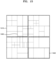
- FIG. 15 illustrates that a plurality of coding units are determined based on a plurality of preset data units included in a picture, according to an embodiment.
- a preset data unit may be defined as a data unit where a coding unit starts to be recursively split by using split shape mode information. That is, the preset data unit may correspond to a coding unit of an uppermost depth, which is used to determine a plurality of coding units split from a current picture.
- the preset data unit is referred to as a reference data unit.
- the reference data unit may have a preset size and a preset shape.
- a reference coding unit may include M ⁇ N samples.
- M and N may be equal to each other, and may be integers expressed as powers of 2. That is, the reference data unit may have a square or non-square shape, and may be split into an integer number of coding units.
- the image decoding apparatus 100 may split the current picture into a plurality of reference data units. According to an embodiment, the image decoding apparatus 100 may split the plurality of reference data units, which are split from the current picture, by using the split shape mode information of each reference data unit.
- the operation of splitting the reference data unit may correspond to a splitting operation using a quadtree structure.
- the image decoding apparatus 100 may previously determine the minimum size allowed for the reference data units included in the current picture. Accordingly, the image decoding apparatus 100 may determine various reference data units having sizes equal to or greater than the minimum size, and may determine one or more coding units by using the split shape mode information with reference to the determined reference data unit.
- the image decoding apparatus 100 may use a square reference coding unit 1500 or a non-square reference coding unit 1502.
- the shape and size of reference coding units may be determined based on various data units capable of including one or more reference coding units (e.g., sequences, pictures, slices, slice segments, tiles, tile groups, largest coding units, or the like).
- the receiver 110 of the image decoding apparatus 100 may obtain, from a bitstream, at least one of reference coding unit shape information and reference coding unit size information with respect to each of the various data units.
- An operation of splitting the square reference coding unit 1500 into one or more coding units has been described above in relation to the operation of splitting the current coding unit 300 of FIG. 3
- an operation of splitting the non-square reference coding unit 1502 into one or more coding units has been described above in relation to the operation of splitting the current coding unit 400 or 450 of FIG. 4 .
- detailed descriptions thereof will not be provided herein.
- the image decoding apparatus 100 may use a PID for identifying the size and shape of reference coding units, to determine the size and shape of reference coding units according to some data units previously determined based on a preset condition. That is, the receiver 110 may obtain, from the bitstream, only the PID for identifying the size and shape of reference coding units with respect to each slice, slice segment, tile, tile group, or largest coding unit which is a data unit satisfying a preset condition (e.g., a data unit having a size equal to or smaller than a slice) among the various data units (e.g., sequences, pictures, slices, slice segments, tiles, tile groups, largest coding units, or the like).
- a preset condition e.g., a data unit having a size equal to or smaller than a slice
- the image decoding apparatus 100 may determine the size and shape of reference data units with respect to each data unit, which satisfies the preset condition, by using the PID.
- the reference coding unit shape information and the reference coding unit size information are obtained and used from the bitstream according to each data unit having a relatively small size, efficiency of using the bitstream may not be high, and therefore, only the PID may be obtained and used instead of directly obtaining the reference coding unit shape information and the reference coding unit size information.
- at least one of the size and shape of reference coding units corresponding to the PID for identifying the size and shape of reference coding units may be previously determined.
- the image decoding apparatus 100 may determine at least one of the size and shape of reference coding units included in a data unit serving as a unit for obtaining the PID, by selecting the previously determined at least one of the size and shape of reference coding units based on the PID.
- the image decoding apparatus 100 may use one or more reference coding units included in a largest coding unit. That is, a largest coding unit split from a picture may include one or more reference coding units, and coding units may be determined by recursively splitting each reference coding unit. According to an embodiment, at least one of a width and height of the largest coding unit may be integer times at least one of the width and height of the reference coding units. According to an embodiment, the size of reference coding units may be obtained by splitting the largest coding unit n times based on a quadtree structure.
- the image decoding apparatus 100 may determine the reference coding units by splitting the largest coding unit n times based on a quadtree structure, and may split the reference coding unit based on at least one of the block shape information and the split shape mode information according to various embodiments.
- the image decoding apparatus 100 may determine one or more processing blocks split from a picture.
- the processing block is a data unit including one or more reference coding units split from a picture, and the one or more reference coding units included in the processing block may be determined according to a specific order. That is, a determination order of one or more reference coding units determined in each processing block may correspond to one of various types of orders for determining reference coding units, and may vary depending on the processing block.
- the determination order of reference coding units, which is determined with respect to each processing block may be one of various orders, e.g., raster scan order, Z-scan, N-scan, up-right diagonal scan, horizontal scan, and vertical scan, but is not limited to the above-mentioned scan orders.
- the image decoding apparatus 100 may obtain processing block size information and may determine the size of one or more processing blocks included in the picture.
- the image decoding apparatus 100 may obtain the processing block size information from a bitstream and may determine the size of one or more processing blocks included in the picture.
- the size of processing blocks may be a preset size of data units, which is indicated by the processing block size information.
- the receiver 110 of the image decoding apparatus 100 may obtain the processing block size information from the bitstream according to each specific data unit.
- the processing block size information may be obtained from the bitstream in a data unit such as an image, sequence, picture, slice, slice segment, tile, or tile group. That is, the receiver 110 may obtain the processing block size information from the bitstream according to each of the various data units, and the image decoding apparatus 100 may determine the size of one or more processing blocks, which are split from the picture, by using the obtained processing block size information.
- the size of the processing blocks may be integer times that of the reference coding units.
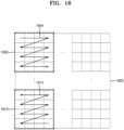
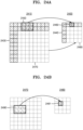
- the image decoding apparatus 100 may determine the size of processing blocks 1602 and 1612 included in the picture 1600. For example, the image decoding apparatus 100 may determine the size of processing blocks based on the processing block size information obtained from the bitstream. Referring to FIG. 16 , according to an embodiment, the image decoding apparatus 100 may determine a width of the processing blocks 1602 and 1612 to be four times the width of the reference coding units, and may determine a height of the processing blocks 1602 and 1612 to be four times the height of the reference coding units. The image decoding apparatus 100 may determine a determination order of one or more reference coding units in one or more processing blocks.
- the image decoding apparatus 100 may determine the processing blocks 1602 and 1612, which are included in the picture 1600, based on the size of processing blocks, and may determine a determination order of one or more reference coding units in the processing blocks 1602 and 1612. According to an embodiment, determination of reference coding units may include determination of the size of the reference coding units.
- the image decoding apparatus 100 may obtain, from the bitstream, determination order information of one or more reference coding units included in one or more processing blocks, and may determine a determination order with respect to one or more reference coding units based on the obtained determination order information.
- the determination order information may be defined as an order or direction for determining the reference coding units in the processing block. That is, the determination order of reference coding units may be independently determined with respect to each processing block.
- the image decoding apparatus 100 may obtain, from the bitstream, the determination order information of reference coding units according to each specific data unit.
- the receiver 110 may obtain the determination order information of reference coding units from the bitstream according to each data unit such as an image, sequence, picture, slice, slice segment, tile, tile group, or processing block. Because the determination order information of reference coding units indicates an order for determining reference coding units in a processing block, the determination order information may be obtained with respect to each specific data unit including an integer number of processing blocks.
- the image decoding apparatus 100 may determine one or more reference coding units based on the determined determination order.
- the receiver 110 may obtain the determination order information of reference coding units from the bitstream as information related to the processing blocks 1602 and 1612, and the image decoding apparatus 100 may determine a determination order of one or more reference coding units included in the processing blocks 1602 and 1612 and determine one or more reference coding units, which are included in the picture 1600, based on the determination order.
- the image decoding apparatus 100 may determine determination orders 1604 and 1614 of one or more reference coding units in the processing blocks 1602 and 1612, respectively. For example, when the determination order information of reference coding units is obtained with respect to each processing block, different types of the determination order information of reference coding units may be obtained for the processing blocks 1602 and 1612.
- reference coding units included in the processing block 1602 may be determined according to a raster scan order.
- determination order 1614 of reference coding units in the other processing block 1612 is a backward raster scan order
- reference coding units included in the processing block 1612 may be determined according to the backward raster scan order.
- the image decoding apparatus 100 may decode the determined one or more reference coding units.
- the image decoding apparatus 100 may decode an image, based on the reference coding units determined as described above.
- a method of decoding the reference coding units may include various image decoding methods.
- the image decoding apparatus 100 may obtain block shape information indicating the shape of a current coding unit or split shape mode information indicating a splitting method of the current coding unit, from the bitstream, and may use the obtained information.
- the split shape mode information may be included in the bitstream related to various data units.
- the image decoding apparatus 100 may use the split shape mode information included in a sequence parameter set, a picture parameter set, a video parameter set, a slice header, a slice segment header, a tile header, or a tile group header.
- the image decoding apparatus 100 may obtain, from the bitstream, a syntax element corresponding to the block shape information or the split shape mode information according to each largest coding unit, each reference coding unit, or each processing block, and may use the obtained syntax element.
- the image decoding apparatus 100 may determine a split rule of an image.
- the split rule may be predetermined between the image decoding apparatus 100 and the image encoding apparatus 2200.
- the image decoding apparatus 100 may determine the split rule of the image, based on information obtained from a bitstream.
- the image decoding apparatus 100 may determine the split rule based on the information obtained from at least one of a sequence parameter set, a picture parameter set, a video parameter set, a slice header, a slice segment header, a tile header, and a tile group header.
- the image decoding apparatus 100 may determine the split rule differently according to frames, slices, tiles, temporal layers, largest coding units, or coding units.
- the image decoding apparatus 100 may determine the split rule based on a block shape of a coding unit.
- the block shape may include a size, shape, a ratio of width and height, and a direction of the coding unit.
- the image encoding apparatus 2200 and the image decoding apparatus 100 may predetermine to determine the split rule based on the block shape of the coding unit.
- the embodiment is not limited thereto.
- the image decoding apparatus 100 may determine the split rule based on the information obtained from the bitstream received from the image encoding apparatus 2200.
- the size of the coding unit may include various sizes, such as 4x4, 8x4, 4x8, 8x8, 16x4, 16x8, and to 256x256.
- the size of the coding unit may be classified based on the length of a long side of the coding unit, the length of a short side, or the area.
- the image decoding apparatus 100 may apply the same split rule to coding units classified as the same group. For example, the image decoding apparatus 100 may classify coding units having the same lengths of the long sides as having the same size. Also, the image decoding apparatus 100 may apply the same split rule to coding units having the same lengths of long sides.
- the ratio of the width and height of the coding unit may include 1:2, 2:1, 1:4, 4:1, 1:8, 8:1, 1:16, 16:1, 32:1, 1:32, or the like.
- a direction of the coding unit may include a horizontal direction and a vertical direction.
- the horizontal direction may indicate a case in which the length of the width of the coding unit is longer than the length of the height thereof.
- the vertical direction may indicate a case in which the length of the width of the coding unit is shorter than the length of the height thereof.
- the image decoding apparatus 100 may adaptively determine the split rule based on the size of the coding unit.
- the image decoding apparatus 100 may differently determine an allowable split shape mode based on the size of the coding unit. For example, the image decoding apparatus 100 may determine whether splitting is allowed based on the size of the coding unit.
- the image decoding apparatus 100 may determine a split direction according to the size of the coding unit.
- the image decoding apparatus 100 may determine an allowable split type according to the size of the coding unit.
- the split rule determined based on the size of the coding unit may be a split rule predetermined between the image encoding apparatus 2200 and the image decoding apparatus 100. Also, the image decoding apparatus 100 may determine the split rule based on the information obtained from the bitstream.
- the image decoding apparatus 100 may adaptively determine the split rule based on a location of the coding unit.
- the image decoding apparatus 100 may adaptively determine the split rule based on the location of the coding unit in the image.
- the image decoding apparatus 100 may determine the split rule such that coding units generated via different splitting paths do not have the same block shape.
- an embodiment is not limited thereto, and the coding units generated via different splitting paths have the same block shape.
- the coding units generated via the different splitting paths may have different decoding processing orders. Because the decoding processing orders have been described above with reference to FIG. 12 , details thereof are not provided again.
- a video encoding apparatus 1700 may include a memory 1710 and at least one processor 1720 connected to the memory 1710. The operations of the video encoding apparatus 1700 according to the embodiment may be performed as individual processors or may be performed under the control of a central processor. Also, the memory 1710 of the video encoding apparatus 1700 may store data received from the outside, data generated by a processor, for example, information about an upper reference line of a current block, etc.
- the processor 1720 of the video encoding apparatus 1700 may be configured to determine whether a current block is in contact with an upper boundary of a largest coding unit including the current block, when it is determined that the current block is in contact with the upper boundary of the largest coding unit, determine an upper reference line of the current block as one reference line, when it is determined that the current block is not in contact with the upper boundary of the largest coding unit, determine the upper reference line of the current block based on N reference lines, and based on the determined upper reference line, perform prediction on the current block.
- the video encoding apparatus 1700 is configured to determine whether a current block is in contact with an upper boundary of a largest coding unit including the current block, when it is determined that the current block is in contact with the upper boundary of the largest coding unit, determine an upper reference line of the current block as one reference line, when it is determined that the current block is not in contact with the upper boundary of the largest coding unit, determine the upper reference line of the current block based on N reference lines, and based on the determined upper reference line, perform prediction on the current block.
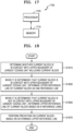
- FIG. 18 illustrates a flowchart of a video encoding method according to an embodiment.
- the video encoding apparatus 1700 may determine whether a current block is in contact with an upper boundary of a largest coding unit including the current block.
- the video encoding apparatus 1700 may determine an upper reference line of the current block as one reference line.
- the one reference line may be a reference line in contact with the upper side of the current block.
- the video encoding apparatus 1700 may determine the upper reference line of the current block based on N reference lines.
- N is a natural number.
- the video encoding apparatus 1700 may generate reference line information indicating a value of N.
- the reference line information when it is determined that the current block is in contact with the upper boundary of the largest coding unit, the reference line information may not be generated.
- the value of N is determined through calculation of sum of transform difference (SATD) or rate distortion optimization (RDO), and thus the reference line information indicating N may be encoded.
- SATD sum of transform difference
- RDO rate distortion optimization
- the upper reference line when it is determined that the current block is not in contact with the upper boundary of the largest coding unit and N is 1, the upper reference line may be determined as a first reference line in contact with the upper side of the current block.
- the upper reference line when it is determined that the current block is not in contact with the upper boundary of the largest coding unit and N is 2, the upper reference line may include the first reference line in contact with the upper side of the current block and a second reference line in contact with the upper side of the first reference line.
- the upper reference line when it is determined that the current block is not in contact with the upper boundary of the largest coding unit and N is 2, the upper reference line may be determined as the second reference line in contact with the upper side of the first reference line in contact with the upper side of the current block. That is, when N is 2, a reference line located second on the upper side of the current block may be determined as the upper reference line.
- the upper reference line may include the first reference line in contact with the upper side of the current block, the second reference line in contact with the upper side of the first reference line, and a fourth reference line in contact with the upper side of a third reference line in contact with the upper side of the second reference line.
- the upper reference line when it is determined that the current block is not in contact with the upper boundary of the largest coding unit and N is 3, the upper reference line may be determined as the fourth reference line in contact with the upper side of the third reference line in contact with the upper side of the second reference line in contact with the upper side of the first reference line in contact with the upper side of the current block. That is, when N is 3, a reference line located fourth on the upper side of the current block may be determined as the upper reference line.
- a left reference line located on the left side of the current block may be determined based on N reference lines located on the left side of the current block.
- the video encoding apparatus 1700 may perform prediction on the current block based on the determined upper reference line.
- prediction on the current block may be performed by using the determined upper reference line and the left reference line determined based on the N reference lines located on the left side of the current block.
- FIGS. 19 and 20 are a block diagram of a video decoding apparatus according to an embodiment and a flowchart of a video decoding method according to an embodiment, which correspond to the video encoding apparatus and the video encoding method described above, respectively.
- FIG. 19 illustrates a block diagram of a video decoding apparatus according to an embodiment.
- a video decoding apparatus 1900 may include a memory 1910 and at least one processor 1920 connected to the memory 1910.
- the operations of the video decoding apparatus 1900 according to the embodiment may be performed as individual processors or may be performed under the control of a central processor.
- the memory 1910 of the video decoding apparatus 1900 may store data received from the outside, data generated by a processor, for example, information about an upper reference line of a current block, etc.
- the processor 1920 of the video decoding apparatus 1900 may be configured to determine whether a current block is in contact with an upper boundary of a largest coding unit including the current block, when it is determined that the current block is in contact with the upper boundary of the largest coding unit, determine an upper reference line of the current block as one reference line, when it is determined that the current block is not in contact with the upper boundary of the largest coding unit, determine the upper reference line of the current block based on N reference lines, and based on the determined upper reference line, perform prediction on the current block.
- the video decoding apparatus 1900 may determine whether a current block is in contact with an upper boundary of a largest coding unit including the current block.
- the video decoding apparatus 1900 may determine an upper reference line of the current block as one reference line.
- the video decoding apparatus 1900 may determine the upper reference line of the current block based on N reference lines.
- N may be determined by reference line information obtained from a bitstream.
- the reference line information when it is determined that the current block is in contact with the upper boundary of the largest coding unit, the reference line information may not be obtained.
- the upper reference line when it is determined that the current block is not in contact with the upper boundary of the largest coding unit and N is 1, the upper reference line may be determined as a first reference line in contact with the upper side of the current block.
- the upper reference line when it is determined that the current block is not in contact with the upper boundary of the largest coding unit and N is 2, the upper reference line may include the first reference line in contact with the upper side of the current block and a second reference line in contact with the upper side of the first reference line.
- the upper reference line when it is determined that the current block is not in contact with the upper boundary of the largest coding unit and N is 2, the upper reference line may be determined as the second reference line in contact with the upper side of the first reference line in contact with the upper side of the current block. That is, when N is 2, a reference line located second on the upper side of the current block may be determined as the upper reference line.
- the upper reference line may include the first reference line in contact with the upper side of the current block, the second reference line in contact with the upper side of the first reference line, and a fourth reference line in contact with the upper side of a third reference line in contact with the upper side of the second reference line.
- the upper reference line when it is determined that the current block is not in contact with the upper boundary of the largest coding unit and N is 3, the upper reference line may be determined as the fourth reference line in contact with the upper side of the third reference line in contact with the upper side of the second reference line in contact with the upper side of the first reference line in contact with the upper side of the current block. That is, when N is 3, a reference line located fourth on the upper side of the current block may be determined as the upper reference line.
- a left reference line located on the left side of the current block may be determined based on N reference lines located on the left side of the current block.
- the video decoding apparatus 1900 may perform prediction on the current block based on the determined upper reference line.
- prediction on the current block may be performed by using the determined upper reference line and the left reference line determined based on the N reference lines located on the left side of the current block.
- the reference sample having no sample value in the upper reference line may be padded by using a predetermined default value. That is, a sample value of the reference sample having no sample value in the upper reference line may be determined as the predetermined default value.
- a reference sample having no sample value in the upper reference line may be padded with a value of the reference sample having a sample value in the upper reference line. That is, a sample value of the reference sample having no sample value in the upper reference line may be determined as the value of the reference sample having a sample value in the upper reference line.
- the reference sample having no sample value in the upper reference line may be regenerated by using the value of the reference sample having a sample value in the upper reference line.
- a sample value of the reference line having no sample value may be padded by using a predetermined default value. That is, the sample value of the reference line having no sample value may be determined as the predetermined default value.
- the reference sample having no sample value when the reference line having no sample value exists in the upper reference line, the reference sample having no sample value may be padded with the value of the reference sample having a sample value. That is, the sample value of the reference line having no sample value may be determined as a sample value of the reference line having a sample value.
- a sample of the reference line having no sample value may be regenerated by using the sample value of the reference line having a sample value.
- the problem of an increase in the size of a reference line buffer caused by using a plurality of reference lines may be solved.
- the plurality of reference lines are stored in the reference line buffer and used, when the current block is in contact with the upper boundary of the largest coding unit including the current block, only one reference line closest to the upper boundary is stored, and thus the size of the buffer may be reduced in terms of the largest coding unit. For example, even though prediction is performed by using only one reference line among a plurality of reference lines, in order to determine which line of the plurality of reference lines to be used, all of the plurality of reference lines are required to be stored. However, when the current block is in contact with the upper boundary, only one reference line in contact with the upper boundary is stored and used, and thus the size of the buffer is reduced in terms of the largest coding unit.
- a method will be described below with reference to FIG. 21 , in which, when the current block is in contact with the upper boundary of the largest coding unit including the current block, one upper reference line is used, and when the current block is not in contact with the upper boundary of the largest coding unit, a reference line is determined based on N upper reference lines.
- FIG. 21 is a diagram for describing a method of using at least one reference line, according to an embodiment.
- reference lines 2121, 2131, 2141, and 2151 located on the upper side of a current block 2110 and reference line 2122, 2132, 2142, and 2152 located on the left side of the current block 2110 may be used.
- the reference lines located on the upper side may include a first upper reference line 2121 in contact with the upper side of the current block 2110, a second upper reference line 2131 in contact with the upper side of the first upper reference line 2121, a third upper reference line 2141 in contact with the upper side of the second upper reference line 2131, and a fourth upper reference line 2151 in contact with the upper side of the third upper reference line 2141.
- the reference lines located on the left side may include a first left reference line 2122 in contact with the left side of the current block 2110, a second left reference line 2132 in contact with the left side of the first left reference line 2122, a third left reference line 2142 in contact with the left side of the second left reference line 2132, and a fourth left reference line 2152 in contact with the left side of the third left reference line 2142.
- the third upper reference line 2141 and the third left reference line 2142 may not be used.
- a third reference line may not be used and at least one of first, second, and fourth reference lines may be used.
- the number of reference lines available for each of the upper and the left sides of a current block is N.
- available does not mean whether a reference line exists, but the possibility that the reference line is used in an algorithm used for prediction.
- MRL index is an index indicating one reference line used for prediction of the current block among a plurality of reference lines used in the multi reference line prediction.
- the first upper reference line 2121 in contact with the upper side of the current block 2110 and first left reference line 2122 in contact with the left side of the current block 2110 may be used. That is, when "MRL index" is 0, the first upper reference line 2121 and the left reference line, which are first reference lines of the upper reference lines and the left reference lines of the current block 2110, may be used.
- the first upper reference line 2121 in contact with the upper side of the current block 2110, the second upper reference line 2131 in contact with the upper side of the first upper reference line 2121, the first left reference line 2122 in contact with the left side of the current block 2110, and the second left reference line 2132 in contact with the left side of the first left reference line 2122 may be used.
- the second upper reference line 2131 on the upper side of the current block 2110 and second left reference line 2132 on the left side of the current block 2110 may be used. That is, when “MRL index" is 1, the second upper reference line 2131 and the second left reference line 2132, which are second reference lines of the upper reference lines and the left reference lines of the current block 2110, may be used.
- the first upper reference line 2121 in contact with the upper side of the current block 2110, the second upper reference line 2131 in contact with the upper side of the first upper reference line 2121, the fourth upper reference line 2151 in contact with the upper side of the third upper reference line 2141 in contact with the upper side of the second upper reference line 2131, the first left reference line 2122 in contact with the left side of the current block 2110, the second left reference line 2132 in contact with the left side of the first left reference line 2122, and the fourth left reference line 2152 in contact with the left side of the third left reference line 2142 in contact with the left side of the second left reference line 2132 may be used.
- three upper reference lines that are the first upper reference line 2121, the second upper reference line 2131, and the fourth upper reference line 2151 and three left reference lines that are the first left reference line 2122, the second left reference line 2132, and the fourth left reference line 2152 may be used.
- the fourth upper reference line 2151 on the upper side of the current block 2110 and fourth left reference line 2152 on the left side of the current block 2110 may be used. That is, when “MRL index” is 2, the fourth upper reference line 2151 and the fourth left reference line 2152, which are fourth reference lines of the upper reference lines and the left reference lines of the current block 2110, may be used.
- the first upper reference line 2121 on the upper side of the current block 2110 and the first left reference line 2122 on the left side of the current block 2110 may be used.
- the current block 2110 when the current block 2110 is in contact with the upper boundary of the largest coding unit including the current block 2110 and N is 2, in prediction on the current block 2110, the first upper reference line 2121 on the upper side of the current block 2110, and the first left reference line 2122 and the second left reference line 2132 on the left side of the current block 2110 may be used.
- the current block 2110 when the current block 2110 is in contact with the upper boundary of the largest coding unit including the current block 2110 and N is 3, in prediction on the current block 2110, the first upper reference line 2121 on the upper side of the current block 2110, and the first left reference line 2122, the second left reference line 2132, and the fourth left reference line 2152 on the left side of the current block 2110 may be used.
- N is determined through SATD or RDO calculation, and thus reference line information indicating N may be signaled.
- the reference line information indicating N may not be generated.
- N may be determined through the signaled reference line information indicating N.
- the reference line information indicating N may not be obtained.
- FIG. 22 illustrates a flowchart of a video encoding method according to another embodiment.
- the video encoding apparatus 1700 of FIG. 17 may perform operations according to the video encoding method of FIG. 22 .
- the video encoding apparatus 1700 may include the memory 1710 and the at least one processor 1720 connected to the memory 1710.
- the operations of the video encoding apparatus 1700 according to the embodiment may be performed as individual processors or may be performed under the control of a central processor.
- the memory 1710 of the video encoding apparatus 1700 may store data received from the outside, data generated by a processor, for example, information about an upper reference line of a current luma block, etc.
- the processor 1720 of the video encoding apparatus 1700 may be configured to determine whether a current luma block is in contact with an upper boundary of a largest coding unit including the current luma block, when it is determined that the current luma block is in contact with the upper boundary of the largest coding unit, determine an upper reference line of the current luma block as one reference line, when it is determined that the current luma block is not in contact with the upper boundary of the largest coding unit, determine the upper reference line of the current luma block as two reference lines, and based on the determined upper reference line, perform prediction on a current chroma block corresponding to the current luma block.
- the video encoding apparatus 1700 may determine whether the current luma block is in contact with the upper boundary of the largest coding unit including the current luma block.
- the video encoding apparatus 1700 may determine an upper reference line of the current luma block as one reference line.
- the video encoding apparatus 1700 may determine the upper reference line of the current luma block as two reference lines.
- the two upper reference lines may include a first reference line in contact with the upper side of the current luma block and a second reference line in contact with the upper side of the first reference line.
- the video encoding apparatus 1700 may perform prediction on a current chroma block corresponding to the current luma block based on the determined upper reference line.
- prediction may be performed on the current chroma block corresponding to the current luma block, based on the determined upper reference line and two left reference lines.
- weight information and deviation information are determined by using a relationship between luma reference samples of the current luma block included in the upper reference line and a chroma reference sample in contact with the upper side of the current chroma block, and the current chroma block is determined based on the weight information, the deviation information, and luma samples of the current luma block so that prediction may be performed on the current chroma block.
- FIG. 23 illustrates a flowchart of a video decoding method according to another embodiment.
- a video decoding apparatus 1900 of FIG. 19 may perform operations according to the video encoding method of FIG. 23 .
- the video decoding apparatus 1900 may include the memory 1910 and the at least one processor 1920 connected to the memory 1910.
- the video decoding apparatus 1900 according to the embodiment may operate as individual processors or may be operated under the control of a central processor.
- the memory 1910 of the video decoding apparatus 1900 may store data received from the outside, data generated by a processor, for example, information about an upper reference line of a current luma block, etc.
- the processor 1920 of the video decoding apparatus 1900 may be configured to determine whether a current luma block is in contact with an upper boundary of a largest coding unit including the current luma block, when it is determined that the current luma block is in contact with the upper boundary of the largest coding unit, determine an upper reference line of the current luma block as one reference line, when it is determined that the current luma block is not in contact with the upper boundary of the largest coding unit, determine the upper reference line of the current luma block as two reference lines, and based on the determined upper reference line, perform prediction on a current chroma block corresponding to the current luma block.
- the video decoding apparatus 1900 may determine whether the current luma block is in contact with the upper boundary of the largest coding unit including the current luma block.
- the video decoding apparatus 1900 may determine an upper reference line of the current luma block as one reference line.
- the video decoding apparatus 1900 may determine the upper reference line of the current luma block as two reference lines.
- the two upper reference lines may include a first reference line in contact with the upper side of the current luma block and a second reference line in contact with the upper side of the first reference line.
- the video decoding apparatus 1900 may perform prediction on a current chroma block corresponding to the current luma block based on the determined upper reference line.
- prediction may be performed on the current chroma block corresponding to the current luma block, based on the determined upper reference line and two left reference lines.
- weight information and deviation information are determined by using a relationship between luma reference samples of the current luma block included in the upper reference line and a chroma reference sample in contact with the upper side of the current chroma block, and the current chroma block is determined based on the weight information, the deviation information, and luma samples of the current luma block so that prediction may be performed on the current chroma block.
- a method of performing prediction on a current chroma block by using a relationship between a luma reference sample of a current luma block and a chroma reference sample of the current chroma block will be described below with reference to FIGS. 24A to 25B .
- FIG. 24A illustrates luma samples located around a current luma block and a chroma sample located around a current chroma block, according to an embodiment
- FIG. 24B illustrates luma samples of a current luma block and a chroma sample of a current chroma block, according to an embodiment.
- weight information and deviation information about a correlation between 6 luma samples L 1 to L 6 2450 among reconstructed adjacent luma samples 2430 neighboring a current luma block 2470 in a luma block 2410 and a chroma sample 2460 of reconstructed adjacent chroma samples 2440 neighboring a current chroma block 2480 in a chroma block 2420 may be derived, and by using the weight information, the deviation information, and reconstructed luma samples L 1 to L 6 2490 of the current luma block 2470, derived by a method expressed by Equation 1, a chroma sample ⁇ 2491 of the current chroma block 2480 may be reconstructed.
- one or more chroma samples may be predicted by using N predetermined luma samples to predict a chroma sample.
- the N predetermined luma samples may be a luma sample of a current luma block corresponding to a location of a chroma sample of a current chroma block and adjacent samples of the luma sample of the corresponding current luma block, or may be the luma sample of the current luma block corresponding to the location of the chroma sample of the current chroma block and arbitrary samples not neighboring the luma sample of the corresponding current luma block.
- a predictor ⁇ of the chroma sample may be expressed by Equation 1 or 2.
- C ⁇ ⁇ 1 ⁇ L 1 + ⁇ 2 ⁇ L 2 + ⁇ 3 ⁇ L 3 + ⁇ 4 ⁇ L 4 + ⁇ 5 ⁇ L 5 + ⁇ 6 ⁇ L 6 + ⁇
- C ⁇ ⁇ 1 L 1 + ⁇ 2 L 2 + ⁇ 3 L 3 + ⁇ 4 L 4 + ⁇ 5 L 5 + ⁇ 6 L 6 + ⁇
- the predictor ⁇ of the chroma sample may represent a value obtained by adding a deviation to a weighted sum of sample values (for example, L 1 ) of luma samples or differences (e.g., ⁇ L 1 ) that are differences between the luma samples and an average value of the luma samples and weights (e.g., ⁇ 1 ) corresponding to the respective samples values or the respective differences.
- sample values for example, L 1
- differences e.g., ⁇ L 1
- weights e.g., ⁇ 1
- some of weights ⁇ 1 to ⁇ N may be zero.
- a prediction mode of an adjacent luma block of a current chroma block may be an intra prediction mode
- weight information may be a modeling parameter value representing a correlation between a luma sample of the adjacent luma block and a chroma sample of an adjacent chroma block
- a chroma sample of a current chroma block may be reconstructed by using 6 luma samples among reconstructed luma samples of the current luma block, 6 weights respectively corresponding to the 6 luma samples, and a deviation value of deviation information, wherein the 6 weights may be a value obtained by multiplying a fixed weight determined in advance according to the intra prediction mode by the modeling parameter value representing the correlation between the luma sample and the chroma sample.
- the modeling parameters ⁇ 1 , ... , ⁇ N may be replaced by s ⁇ ' ip,1 , ... , s ⁇ ' ip,N , respectively, and according to the intra prediction mode, the modeling parameters s ⁇ ' ip,1 , ... , s ⁇ ' ip,N may use only modeling parameters s and ⁇ by fixing a value of ⁇ ' ip,1 , ... , ⁇ ' ip,N .
- the weights ⁇ ' ip,1 ,..., ⁇ ' ip,N fixed according to the intra prediction mode may have the same value in the form of a Gaussian filter, etc. regardless of the intra prediction mode, or have different values according to the intra prediction mode.
- FIG. 25A illustrates luma samples located around a current luma block and a chroma sample located around a current chroma block, according to another embodiment
- FIG. 25B illustrates luma samples of a current luma block and a chroma sample of a current chroma block, according to another embodiment.
- weight information and deviation information about a correlation between 3 luma samples L' 1 to L' 3 2550 included in one reference line in contact with the upper side of a current luma block 2570 among reconstructed adjacent luma samples 2530 neighboring the current luma block 2570 in a luma block 2510 and a chroma sample 2560 of reconstructed adjacent chroma samples 2540 neighboring a current chroma block 2580 in a chroma block 2520 may be derived, and by using the weight information, the deviation information, and reconstructed luma samples L' 1 to L' 3 2590 of the current luma block 2570, derived by a method expressed by Equation 1, a chroma sample ⁇ 2591 of the current chroma block 2580 may be reconstructed.
- weight information and deviation information about a correlation between 6 adjacent luma samples and an adjacent chroma sample are derived, and by using the reconstructed luma samples L 1 to L 6 2490 of the current luma block 2470, the chroma sample ⁇ 2491 of the current chroma block 2480 may be reconstructed.
- the number and locations of samples to be used to predict a chroma block from a luma block under a condition of using one reference line in contact with the upper side of the current luma block may be changed according to an algorithm.
- the number and locations of the samples to be used to predict the chroma block from the luma block may be changed according to the algorithm.
- FIG. 26A illustrates an embodiment in which the number of upper reference lines is different from the number of left reference lines
- FIG. 26B illustrates an embodiment in which the number of upper reference lines is the same as the number of left reference lines
- FIG. 26C illustrates an embodiment in which, when the number of upper reference lines is different from the number of left reference lines, padding is performed so that the number of upper reference lines and the number of left reference line are the same.
- the number of an upper reference line 2620 of a current block 2610 may be different from the number of a left reference line 2630 of the current block 2610.
- the number of the upper reference line 2620 located on the upper side of the current block 2610 is determined as N
- the number of the left reference line 2630 located on the left side of the current block 2610 is determined as M, wherein M may be greater than or equal to N.
- whether one reference line or use N predetermined reference lines are to be used may be determined through a flag. Whether the one reference line or use the N predetermined reference lines are to be used may be determined through a flag in a frame unit, a largest coding unit, or a block unit.
- whether one reference line or N predetermined reference lines are to be used by a decoding apparatus may be determined without a separate flag, depending on the availability of a reference block of the current block.
- the flag When the current block is in contact with the upper boundary of the largest coding unit including the current block, in a case where a flag indicating whether one reference line or N predetermined reference lines are to be used, the flag may be simultaneously applied to both a luma block and a chroma block, or may be individually applied to a luma block and a chroma block. Also, when the current block is in contact with the upper boundary of the largest coding unit including the current block, whether one reference line or N predetermined reference lines are to be used may be determined according to different criteria (e.g., a block size, an intra mode, reference availability) for each of the luma block and the chroma block.
- criteria e.g., a block size, an intra mode, reference availability
- whether one reference line or N predetermined reference lines are to be used may be determined according to a size of the current block without signaling of the flag.
- a flag of a tool e.g., LM chroma, adaptive loop filter (ALF), etc.
- ALF adaptive loop filter
- a rate of a flag of the adjacent largest coding unit being turned on is M % (e.g., M is 50) or higher
- M % e.g., M is 50
- all of largest coding units available as adjacent largest coding units may be used, or information about whether tools of only some largest coding units are turned on may be selectively used.
- not all of the adjacent largest coding units are used, and only information about whether a tool of a coding unit adjacent to the largest coding unit including the current block is turned on/off may be used.
- whether the flag is to be applied may be determined without separate signaling.
- both the number of an upper reference line 2621 of the current block 2611 and the number of a left reference line 2631 of the current block 2611 may be determined as M.
- an area equal to M-N above the N upper reference lines 2622 may be filled by padding the area with upper pixels of the N upper reference lines 2622.
- pixels of the area equal to M-N may be generated by using pixels of one or more reference lines in the N upper reference lines 2622.
- various methods such as padding, extrapolation, filtering, etc. may be used as generation methods.
- the area equal to M-N above the N upper reference line 2622 may be filled by padding the area with a gradient between to two adjacent reference lines.
- the aforedescribed embodiments of the disclosure may be written as a program executable on a computer, and may be implemented in general-use digital computers that execute the program by using a computer-readable recording medium.
- the computer-readable recording medium include magnetic storage media (e.g., ROM, floppy disks, hard disks, etc.), optical recording media (e.g., CD-ROMs, or DVDs), or the like.
- the invention might include, relate to, and/or be defined by, the following aspects:
Landscapes
- Engineering & Computer Science (AREA)
- Multimedia (AREA)
- Signal Processing (AREA)
- Computing Systems (AREA)
- Theoretical Computer Science (AREA)
- Compression Or Coding Systems Of Tv Signals (AREA)
Applications Claiming Priority (3)
| Application Number | Priority Date | Filing Date | Title |
|---|---|---|---|
| US201862696584P | 2018-07-11 | 2018-07-11 | |
| PCT/KR2019/008565 WO2020013627A1 (ko) | 2018-07-11 | 2019-07-11 | 비디오 복호화 방법 및 장치, 비디오 부호화 방법 및 장치 |
| EP19834458.2A EP3823283B1 (de) | 2018-07-11 | 2019-07-11 | Verfahren und vorrichtung für die videodekodierung, und verfahren und vorrichtung für die videokodierung |
Related Parent Applications (2)
| Application Number | Title | Priority Date | Filing Date |
|---|---|---|---|
| EP19834458.2A Division EP3823283B1 (de) | 2018-07-11 | 2019-07-11 | Verfahren und vorrichtung für die videodekodierung, und verfahren und vorrichtung für die videokodierung |
| EP19834458.2A Division-Into EP3823283B1 (de) | 2018-07-11 | 2019-07-11 | Verfahren und vorrichtung für die videodekodierung, und verfahren und vorrichtung für die videokodierung |
Publications (2)
| Publication Number | Publication Date |
|---|---|
| EP4543007A2 true EP4543007A2 (de) | 2025-04-23 |
| EP4543007A3 EP4543007A3 (de) | 2025-07-30 |
Family
ID=69141499
Family Applications (5)
| Application Number | Title | Priority Date | Filing Date |
|---|---|---|---|
| EP25162799.8A Pending EP4543006A3 (de) | 2018-07-11 | 2019-07-11 | Verfahren und vorrichtung für die videodekodierung, und verfahren und vorrichtung für die videokodierung |
| EP25162800.4A Pending EP4543007A3 (de) | 2018-07-11 | 2019-07-11 | Verfahren und vorrichtung für die videodekodierung, und verfahren und vorrichtung für die videokodierung |
| EP25162798.0A Pending EP4543005A3 (de) | 2018-07-11 | 2019-07-11 | Verfahren und vorrichtung für die videodekodierung, und verfahren und vorrichtung für die videokodierung |
| EP25162801.2A Pending EP4543008A3 (de) | 2018-07-11 | 2019-07-11 | Verfahren und vorrichtung für die videodekodierung, und verfahren und vorrichtung für die videokodierung |
| EP19834458.2A Active EP3823283B1 (de) | 2018-07-11 | 2019-07-11 | Verfahren und vorrichtung für die videodekodierung, und verfahren und vorrichtung für die videokodierung |
Family Applications Before (1)
| Application Number | Title | Priority Date | Filing Date |
|---|---|---|---|
| EP25162799.8A Pending EP4543006A3 (de) | 2018-07-11 | 2019-07-11 | Verfahren und vorrichtung für die videodekodierung, und verfahren und vorrichtung für die videokodierung |
Family Applications After (3)
| Application Number | Title | Priority Date | Filing Date |
|---|---|---|---|
| EP25162798.0A Pending EP4543005A3 (de) | 2018-07-11 | 2019-07-11 | Verfahren und vorrichtung für die videodekodierung, und verfahren und vorrichtung für die videokodierung |
| EP25162801.2A Pending EP4543008A3 (de) | 2018-07-11 | 2019-07-11 | Verfahren und vorrichtung für die videodekodierung, und verfahren und vorrichtung für die videokodierung |
| EP19834458.2A Active EP3823283B1 (de) | 2018-07-11 | 2019-07-11 | Verfahren und vorrichtung für die videodekodierung, und verfahren und vorrichtung für die videokodierung |
Country Status (9)
| Country | Link |
|---|---|
| US (5) | US11736682B2 (de) |
| EP (5) | EP4543006A3 (de) |
| KR (1) | KR20210019401A (de) |
| CN (5) | CN118200529A (de) |
| BR (1) | BR112021000224A2 (de) |
| ES (1) | ES3028094T3 (de) |
| HU (1) | HUE071496T2 (de) |
| PL (1) | PL3823283T3 (de) |
| WO (1) | WO2020013627A1 (de) |
Families Citing this family (6)
| Publication number | Priority date | Publication date | Assignee | Title |
|---|---|---|---|---|
| US20220321909A1 (en) * | 2021-03-31 | 2022-10-06 | Tencent America LLC | Harmonized design between multiple reference line intra prediction and transform partitioning |
| US12069305B2 (en) * | 2021-04-16 | 2024-08-20 | Tencent America LLC | Low memory design for multiple reference line selection scheme |
| WO2023133245A1 (en) * | 2022-01-06 | 2023-07-13 | Ofinno, Llc | Boundary based asymmetric reference line offsets |
| WO2023140547A1 (ko) * | 2022-01-19 | 2023-07-27 | 현대자동차주식회사 | 다중 참조라인들을 이용하는 크로마 채널 코딩을 위한 방법 및 장치 |
| WO2025005610A1 (ko) * | 2023-06-27 | 2025-01-02 | 주식회사 케이티 | 영상 부호화/복호화 방법 및 비트스트림을 저장하는 기록 매체 |
| WO2025076066A1 (en) * | 2023-10-05 | 2025-04-10 | Beijing Dajia Internet Information Technology Co., Ltd | Methods and devices of extrapolation filter-based prediction mode |
Family Cites Families (15)
| Publication number | Priority date | Publication date | Assignee | Title |
|---|---|---|---|---|
| KR101330630B1 (ko) * | 2006-03-13 | 2013-11-22 | 삼성전자주식회사 | 최적인 예측 모드를 적응적으로 적용하여 동영상을부호화하는 방법 및 장치, 동영상을 복호화하는 방법 및장치 |
| KR101663235B1 (ko) | 2009-12-14 | 2016-10-06 | 한국과학기술원 | 화면 내 예측 부호화/복호화 방법 및 장치 |
| CN102316317B (zh) * | 2010-07-10 | 2013-04-24 | 华为技术有限公司 | 一种生成图像预测值的方法和装置 |
| US20120314767A1 (en) | 2011-06-13 | 2012-12-13 | Qualcomm Incorporated | Border pixel padding for intra prediction in video coding |
| JP2013141187A (ja) | 2012-01-06 | 2013-07-18 | Sony Corp | 画像処理装置及び画像処理方法 |
| CN111193930B (zh) * | 2013-12-16 | 2021-11-30 | 浙江大学 | 一种前向双假设编码图像块的编解码方法和装置 |
| US10645414B2 (en) | 2015-11-11 | 2020-05-05 | Samsung Electronics Co., Ltd. | Method for encoding/decoding image, and device therefor |
| WO2017090993A1 (ko) | 2015-11-24 | 2017-06-01 | 삼성전자 주식회사 | 비디오 복호화 방법 및 그 장치 및 비디오 부호화 방법 및 그 장치 |
| US10390021B2 (en) * | 2016-03-18 | 2019-08-20 | Mediatek Inc. | Method and apparatus of video coding |
| EP3453180A4 (de) * | 2016-05-04 | 2020-04-01 | Microsoft Technology Licensing, LLC | Intra-bild-vorhersage unter verwendung nicht benachbarter referenzlinien von abtastwerten |
| US10484712B2 (en) * | 2016-06-08 | 2019-11-19 | Qualcomm Incorporated | Implicit coding of reference line index used in intra prediction |
| US11128862B2 (en) | 2016-09-13 | 2021-09-21 | Research and Telecommunications Research Insitute | Video encoding/decoding method and device, and recording medium having bitstream stored therein |
| CN118678062A (zh) | 2016-10-04 | 2024-09-20 | Lx 半导体科技有限公司 | 编码/解码设备和发送图像数据的设备 |
| CN115037932B (zh) * | 2017-10-18 | 2025-08-26 | 英迪股份有限公司 | 图像编码/解码方法和装置以及存储有比特流的记录介质 |
| KR20250057088A (ko) * | 2018-03-16 | 2025-04-28 | 비보 모바일 커뮤니케이션 컴퍼니 리미티드 | 인트라 예측 기반 영상/비디오 코딩 방법 및 그 장치 |
-
2019
- 2019-07-11 CN CN202410338608.9A patent/CN118200529A/zh active Pending
- 2019-07-11 CN CN202410338699.6A patent/CN118200531A/zh active Pending
- 2019-07-11 CN CN202410338558.4A patent/CN118233629A/zh active Pending
- 2019-07-11 EP EP25162799.8A patent/EP4543006A3/de active Pending
- 2019-07-11 CN CN201980059676.9A patent/CN112690001B/zh active Active
- 2019-07-11 EP EP25162800.4A patent/EP4543007A3/de active Pending
- 2019-07-11 KR KR1020207028109A patent/KR20210019401A/ko not_active Ceased
- 2019-07-11 ES ES19834458T patent/ES3028094T3/es active Active
- 2019-07-11 WO PCT/KR2019/008565 patent/WO2020013627A1/ko not_active Ceased
- 2019-07-11 CN CN202410338640.7A patent/CN118200530A/zh active Pending
- 2019-07-11 US US17/259,455 patent/US11736682B2/en active Active
- 2019-07-11 PL PL19834458.2T patent/PL3823283T3/pl unknown
- 2019-07-11 EP EP25162798.0A patent/EP4543005A3/de active Pending
- 2019-07-11 EP EP25162801.2A patent/EP4543008A3/de active Pending
- 2019-07-11 BR BR112021000224-3A patent/BR112021000224A2/pt unknown
- 2019-07-11 HU HUE19834458A patent/HUE071496T2/hu unknown
- 2019-07-11 EP EP19834458.2A patent/EP3823283B1/de active Active
-
2023
- 2023-07-19 US US18/354,888 patent/US20230362359A1/en active Pending
- 2023-07-19 US US18/354,850 patent/US20230362357A1/en active Pending
- 2023-07-19 US US18/354,839 patent/US12445600B2/en active Active
- 2023-07-19 US US18/354,870 patent/US12368843B2/en active Active
Also Published As
| Publication number | Publication date |
|---|---|
| EP4543008A2 (de) | 2025-04-23 |
| US12368843B2 (en) | 2025-07-22 |
| HUE071496T2 (hu) | 2025-09-28 |
| US20230370583A1 (en) | 2023-11-16 |
| EP3823283A1 (de) | 2021-05-19 |
| US20230362357A1 (en) | 2023-11-09 |
| EP4543005A2 (de) | 2025-04-23 |
| EP3823283C0 (de) | 2025-04-30 |
| US11736682B2 (en) | 2023-08-22 |
| BR112021000224A2 (pt) | 2021-04-06 |
| EP3823283A4 (de) | 2022-06-08 |
| EP4543006A3 (de) | 2025-07-30 |
| EP4543007A3 (de) | 2025-07-30 |
| EP4543005A3 (de) | 2025-07-30 |
| US20230362358A1 (en) | 2023-11-09 |
| EP3823283B1 (de) | 2025-04-30 |
| CN112690001B (zh) | 2024-04-12 |
| CN118233629A (zh) | 2024-06-21 |
| US12445600B2 (en) | 2025-10-14 |
| PL3823283T3 (pl) | 2025-06-30 |
| EP4543006A2 (de) | 2025-04-23 |
| WO2020013627A1 (ko) | 2020-01-16 |
| ES3028094T3 (en) | 2025-06-18 |
| CN118200529A (zh) | 2024-06-14 |
| CN118200530A (zh) | 2024-06-14 |
| CN112690001A (zh) | 2021-04-20 |
| CN118200531A (zh) | 2024-06-14 |
| US20210281834A1 (en) | 2021-09-09 |
| EP4543008A3 (de) | 2025-07-30 |
| KR20210019401A (ko) | 2021-02-22 |
| US20230362359A1 (en) | 2023-11-09 |
Similar Documents
| Publication | Publication Date | Title |
|---|---|---|
| AU2023270341B2 (en) | Video decoding method and apparatus, and video encoding method and apparatus | |
| EP3823283B1 (de) | Verfahren und vorrichtung für die videodekodierung, und verfahren und vorrichtung für die videokodierung | |
| EP3843391A1 (de) | Videodekodierungsverfahren und -apparat, und videokodierungsverfahren und -apparat | |
| KR20200100656A (ko) | 비디오 복호화 방법 및 장치, 비디오 부호화 방법 및 장치 | |
| KR20200047563A (ko) | 크로스-성분 예측에 의한 비디오 복호화 방법 및 장치, 크로스-성분 예측에 의한 비디오 부호화 방법 및 장치 | |
| EP3700202A1 (de) | Verfahren und vorrichtung zur videocodierung sowie verfahren und vorrichtung zur videodecodierung | |
| KR102281281B1 (ko) | 비디오 복호화 방법 및 장치, 비디오 부호화 방법 및 장치 | |
| KR102333181B1 (ko) | 비디오 복호화 방법 및 장치, 비디오 부호화 방법 및 장치 |
Legal Events
| Date | Code | Title | Description |
|---|---|---|---|
| PUAI | Public reference made under article 153(3) epc to a published international application that has entered the european phase |
Free format text: ORIGINAL CODE: 0009012 |
|
| STAA | Information on the status of an ep patent application or granted ep patent |
Free format text: STATUS: THE APPLICATION HAS BEEN PUBLISHED |
|
| AC | Divisional application: reference to earlier application |
Ref document number: 3823283 Country of ref document: EP Kind code of ref document: P |
|
| AK | Designated contracting states |
Kind code of ref document: A2 Designated state(s): AL AT BE BG CH CY CZ DE DK EE ES FI FR GB GR HR HU IE IS IT LI LT LU LV MC MK MT NL NO PL PT RO RS SE SI SK SM TR |
|
| REG | Reference to a national code |
Ref country code: DE Ref legal event code: R079 Free format text: PREVIOUS MAIN CLASS: H04N0019960000 Ipc: H04N0019140000 |
|
| PUAL | Search report despatched |
Free format text: ORIGINAL CODE: 0009013 |
|
| AK | Designated contracting states |
Kind code of ref document: A3 Designated state(s): AL AT BE BG CH CY CZ DE DK EE ES FI FR GB GR HR HU IE IS IT LI LT LU LV MC MK MT NL NO PL PT RO RS SE SI SK SM TR |
|
| RIC1 | Information provided on ipc code assigned before grant |
Ipc: H04N 19/14 20140101AFI20250625BHEP Ipc: H04N 19/105 20140101ALI20250625BHEP Ipc: H04N 19/176 20140101ALI20250625BHEP Ipc: H04N 19/50 20140101ALI20250625BHEP Ipc: H04N 19/132 20140101ALI20250625BHEP Ipc: H04N 19/426 20140101ALI20250625BHEP Ipc: H04N 19/119 20140101ALI20250625BHEP Ipc: H04N 19/186 20140101ALI20250625BHEP Ipc: H04N 19/196 20140101ALI20250625BHEP Ipc: H04N 19/593 20140101ALI20250625BHEP Ipc: H04N 19/96 20140101ALI20250625BHEP |
|
| STAA | Information on the status of an ep patent application or granted ep patent |
Free format text: STATUS: REQUEST FOR EXAMINATION WAS MADE |
|
| 17P | Request for examination filed |
Effective date: 20251022 |