EP4542702A1 - Vorrichtung zum halten und bewegen von lithiumbatteriezellen während der herstellung und verfahren zur herstellung einer vielzahl von lithiumbatteriezellen mit der vorrichtung - Google Patents
Vorrichtung zum halten und bewegen von lithiumbatteriezellen während der herstellung und verfahren zur herstellung einer vielzahl von lithiumbatteriezellen mit der vorrichtung Download PDFInfo
- Publication number
- EP4542702A1 EP4542702A1 EP24198601.7A EP24198601A EP4542702A1 EP 4542702 A1 EP4542702 A1 EP 4542702A1 EP 24198601 A EP24198601 A EP 24198601A EP 4542702 A1 EP4542702 A1 EP 4542702A1
- Authority
- EP
- European Patent Office
- Prior art keywords
- cell
- cells
- holding member
- expansion
- during
- Prior art date
- Legal status (The legal status is an assumption and is not a legal conclusion. Google has not performed a legal analysis and makes no representation as to the accuracy of the status listed.)
- Granted
Links
Images







Classifications
-
- H—ELECTRICITY
- H01—ELECTRIC ELEMENTS
- H01M—PROCESSES OR MEANS, e.g. BATTERIES, FOR THE DIRECT CONVERSION OF CHEMICAL ENERGY INTO ELECTRICAL ENERGY
- H01M10/00—Secondary cells; Manufacture thereof
- H01M10/04—Construction or manufacture in general
- H01M10/0404—Machines for assembling batteries
-
- H—ELECTRICITY
- H01—ELECTRIC ELEMENTS
- H01M—PROCESSES OR MEANS, e.g. BATTERIES, FOR THE DIRECT CONVERSION OF CHEMICAL ENERGY INTO ELECTRICAL ENERGY
- H01M10/00—Secondary cells; Manufacture thereof
- H01M10/05—Accumulators with non-aqueous electrolyte
- H01M10/058—Construction or manufacture
-
- H—ELECTRICITY
- H01—ELECTRIC ELEMENTS
- H01M—PROCESSES OR MEANS, e.g. BATTERIES, FOR THE DIRECT CONVERSION OF CHEMICAL ENERGY INTO ELECTRICAL ENERGY
- H01M10/00—Secondary cells; Manufacture thereof
- H01M10/04—Construction or manufacture in general
- H01M10/049—Processes for forming or storing electrodes in the battery container
-
- H—ELECTRICITY
- H01—ELECTRIC ELEMENTS
- H01M—PROCESSES OR MEANS, e.g. BATTERIES, FOR THE DIRECT CONVERSION OF CHEMICAL ENERGY INTO ELECTRICAL ENERGY
- H01M10/00—Secondary cells; Manufacture thereof
- H01M10/42—Methods or arrangements for servicing or maintenance of secondary cells or secondary half-cells
- H01M10/44—Methods for charging or discharging
- H01M10/441—Methods for charging or discharging for several batteries or cells simultaneously or sequentially
-
- H—ELECTRICITY
- H01—ELECTRIC ELEMENTS
- H01M—PROCESSES OR MEANS, e.g. BATTERIES, FOR THE DIRECT CONVERSION OF CHEMICAL ENERGY INTO ELECTRICAL ENERGY
- H01M10/00—Secondary cells; Manufacture thereof
- H01M10/42—Methods or arrangements for servicing or maintenance of secondary cells or secondary half-cells
- H01M10/44—Methods for charging or discharging
- H01M10/446—Initial charging measures
-
- H—ELECTRICITY
- H01—ELECTRIC ELEMENTS
- H01M—PROCESSES OR MEANS, e.g. BATTERIES, FOR THE DIRECT CONVERSION OF CHEMICAL ENERGY INTO ELECTRICAL ENERGY
- H01M50/00—Constructional details or processes of manufacture of the non-active parts of electrochemical cells other than fuel cells, e.g. hybrid cells
- H01M50/20—Mountings; Secondary casings or frames; Racks, modules or packs; Suspension devices; Shock absorbers; Transport or carrying devices; Holders
- H01M50/244—Secondary casings; Racks; Suspension devices; Carrying devices; Holders characterised by their mounting method
-
- H—ELECTRICITY
- H01—ELECTRIC ELEMENTS
- H01M—PROCESSES OR MEANS, e.g. BATTERIES, FOR THE DIRECT CONVERSION OF CHEMICAL ENERGY INTO ELECTRICAL ENERGY
- H01M50/00—Constructional details or processes of manufacture of the non-active parts of electrochemical cells other than fuel cells, e.g. hybrid cells
- H01M50/30—Arrangements for facilitating escape of gases
-
- H—ELECTRICITY
- H01—ELECTRIC ELEMENTS
- H01M—PROCESSES OR MEANS, e.g. BATTERIES, FOR THE DIRECT CONVERSION OF CHEMICAL ENERGY INTO ELECTRICAL ENERGY
- H01M50/00—Constructional details or processes of manufacture of the non-active parts of electrochemical cells other than fuel cells, e.g. hybrid cells
- H01M50/30—Arrangements for facilitating escape of gases
- H01M50/317—Re-sealable arrangements
-
- H—ELECTRICITY
- H01—ELECTRIC ELEMENTS
- H01M—PROCESSES OR MEANS, e.g. BATTERIES, FOR THE DIRECT CONVERSION OF CHEMICAL ENERGY INTO ELECTRICAL ENERGY
- H01M50/00—Constructional details or processes of manufacture of the non-active parts of electrochemical cells other than fuel cells, e.g. hybrid cells
- H01M50/60—Arrangements or processes for filling or topping-up with liquids; Arrangements or processes for draining liquids from casings
- H01M50/609—Arrangements or processes for filling with liquid, e.g. electrolytes
-
- H—ELECTRICITY
- H01—ELECTRIC ELEMENTS
- H01M—PROCESSES OR MEANS, e.g. BATTERIES, FOR THE DIRECT CONVERSION OF CHEMICAL ENERGY INTO ELECTRICAL ENERGY
- H01M50/00—Constructional details or processes of manufacture of the non-active parts of electrochemical cells other than fuel cells, e.g. hybrid cells
- H01M50/60—Arrangements or processes for filling or topping-up with liquids; Arrangements or processes for draining liquids from casings
- H01M50/609—Arrangements or processes for filling with liquid, e.g. electrolytes
- H01M50/627—Filling ports
- H01M50/636—Closing or sealing filling ports, e.g. using lids
-
- H—ELECTRICITY
- H01—ELECTRIC ELEMENTS
- H01M—PROCESSES OR MEANS, e.g. BATTERIES, FOR THE DIRECT CONVERSION OF CHEMICAL ENERGY INTO ELECTRICAL ENERGY
- H01M4/00—Electrodes
- H01M4/02—Electrodes composed of, or comprising, active material
- H01M4/04—Processes of manufacture in general
- H01M4/0438—Processes of manufacture in general by electrochemical processing
- H01M4/044—Activating, forming or electrochemical attack of the supporting material
- H01M4/0445—Forming after manufacture of the electrode, e.g. first charge, cycling
- H01M4/0447—Forming after manufacture of the electrode, e.g. first charge, cycling of complete cells or cells stacks
-
- H—ELECTRICITY
- H01—ELECTRIC ELEMENTS
- H01M—PROCESSES OR MEANS, e.g. BATTERIES, FOR THE DIRECT CONVERSION OF CHEMICAL ENERGY INTO ELECTRICAL ENERGY
- H01M50/00—Constructional details or processes of manufacture of the non-active parts of electrochemical cells other than fuel cells, e.g. hybrid cells
- H01M50/60—Arrangements or processes for filling or topping-up with liquids; Arrangements or processes for draining liquids from casings
- H01M50/609—Arrangements or processes for filling with liquid, e.g. electrolytes
- H01M50/627—Filling ports
-
- Y—GENERAL TAGGING OF NEW TECHNOLOGICAL DEVELOPMENTS; GENERAL TAGGING OF CROSS-SECTIONAL TECHNOLOGIES SPANNING OVER SEVERAL SECTIONS OF THE IPC; TECHNICAL SUBJECTS COVERED BY FORMER USPC CROSS-REFERENCE ART COLLECTIONS [XRACs] AND DIGESTS
- Y02—TECHNOLOGIES OR APPLICATIONS FOR MITIGATION OR ADAPTATION AGAINST CLIMATE CHANGE
- Y02E—REDUCTION OF GREENHOUSE GAS [GHG] EMISSIONS, RELATED TO ENERGY GENERATION, TRANSMISSION OR DISTRIBUTION
- Y02E60/00—Enabling technologies; Technologies with a potential or indirect contribution to GHG emissions mitigation
- Y02E60/10—Energy storage using batteries
-
- Y—GENERAL TAGGING OF NEW TECHNOLOGICAL DEVELOPMENTS; GENERAL TAGGING OF CROSS-SECTIONAL TECHNOLOGIES SPANNING OVER SEVERAL SECTIONS OF THE IPC; TECHNICAL SUBJECTS COVERED BY FORMER USPC CROSS-REFERENCE ART COLLECTIONS [XRACs] AND DIGESTS
- Y02—TECHNOLOGIES OR APPLICATIONS FOR MITIGATION OR ADAPTATION AGAINST CLIMATE CHANGE
- Y02P—CLIMATE CHANGE MITIGATION TECHNOLOGIES IN THE PRODUCTION OR PROCESSING OF GOODS
- Y02P70/00—Climate change mitigation technologies in the production process for final industrial or consumer products
- Y02P70/50—Manufacturing or production processes characterised by the final manufactured product
Definitions
- This invention relates, firstly, to a device for holding and moving lithium battery cells during production, in particular for holding and moving cells with a rigid outer case which are not yet sealed, which must be subjected to a forming (first charging) process outside of the controlled-atmosphere environments in which they are assembled (in the sector known as dry rooms, that is to say, clean rooms with extremely low humidity levels in the air).
- this invention allows the safe movement of cells which are not yet sealed even outside of the dry rooms and has the great advantage of notably simplifying the degassing operations which must be carried out at the end of the forming process.
- this invention is intended for the production of prismatic lithium cells but can similarly be advantageously applied even for cylindrical lithium cells.
- this invention also relates to a method for producing a plurality of lithium battery cells which uses the above-mentioned device to safely carry out the forming process for cells which are not yet sealed outside the dry rooms.
- a lithium-ion battery (widely known simply as a lithium battery) is the individual cells of which it is made up, which are the elements that allow the battery to store and to supply electric energy.
- lithium-ion cells There are three most common types of lithium-ion cells on the market, cylindrical cells, prismatic cells and pouch cells.
- This invention can be applied only for the first two types, in which each cell has a substantially rigid outer case.
- Cylindrical cells are usually used in medium-small battery packs, whilst prismatic cells are usually used to create the lithium batteries dedicated to sectors which require medium-high storage capacity, such as the sector of machines and industrial vehicles, or that of energy storage.
- Both types of cells generally have an aluminium or plastic material case which is very strong and they may come in various sizes and shapes depending on the field of application.
- lithium-ion cells contain two electrodes, that is to say, a cathode (positive pole) and an anode (negative pole). Interposed between the two electrodes there is a separator, that is to say, a layer of thin material, usually made of a plastic polymer or ceramic whose function is to act as insulation between the two electrodes. Finally, the electrodes and the separator are completely submerged in an electrolyte, a liquid containing lithium salts, which fills the inner volume of the cell and which during use allows electric energy to circulate between the two electrodes.
- each electrode Whilst in the cylindrical cells the two electrodes are each constituted of a single thin sheet of conductive material, and the two sheets are wound in a single roll interposing between them two continuous sheets of separator, in the prismatic cells each electrode comprises a plurality of distinct sheets superposed on each other which are electrically connected to each other by suitable protruding tabs.
- the individual sheets of each electrode alternate with those of the other electrode, with the separator interposed between them (the latter may also be in the form of individual sheets or be a continuous sheet folded on itself in a Z shape).
- the end result in prismatic cells is that the two electrodes and the separator constitute what is defined as a pack which substantially has the shape of a parallelepiped.
- the tabs of the sheets which constitute the electrodes protrude from the pack in two distinct positions, those of the sheets of the cathode which are aligned and superposed on each other and those of the sheets of the anode which are aligned and superposed on each other.
- the tabs of the two inner electrodes are also connected to respective terminals (positive and negative) fixed on a lid of the outer case.
- the first step is to make the pack comprising the electrodes and the separator (also meaning the roll in the case of cylindrical cells). Then, the pack is inserted into a main body of the outer case and the two electrodes are electrically connected to the respective terminals present on the lid.
- the lid is fixed in a sealed fashion to the main body to close the inner volume.
- the lid has a through hole which connects the inner volume with the surrounding environment and which has the function of allowing the next step to be carried out in which the electrolyte is inserted into the inner volume.
- the quantity of electrolyte inserted is usually predetermined and in excess in order to take into account the fact that a certain quantity of it will then evaporate in the subsequent working steps.
- the liquid electrolyte, fed through the through hole, is gradually absorbed by the pack due to capillarity (in fact, where it is essential to have the liquid is in the middle of the pack, between all of the sheets of the electrodes and of the separator). Filling is a slow process, since it is necessary to allow the liquid time to be absorbed without making it come out of the access port through which it is fed.
- the cell production process is still far from over.
- only correct carrying out of the forming process causes electrical activation of the cell and renders it capable of subsequently being used to store and release electric energy.
- the forming process is a long process (it may even last 8h-10h) and has the disadvantage of causing gases to be created inside the cell mainly as a result of evaporation of part of the electrolyte.
- the only option is therefore to perform the forming process outside the dry room, taking care to seal the through hole at the end of assembly in order to be able to move the cells outside, without the risk of compromising the quality of the inner components.
- the disadvantage of that choice is that the gases which are created during forming of the cell cannot come out and they remain trapped inside the cell, in particular in a space deliberately left empty, which is located between the upper level of the electrolyte and the lid.
- a cell degassing step is provided, during which the hole is re-opened and the excess gas is made to come out of the cell.
- This step must also be carried out inside the dry room in order to avoid the risk of deterioration of the inner components. Only at the end of the degassing step can the cell be finally sealed, after any electrolyte top-up if necessary, and be sent on for subsequent ageing and charging-discharging steps.
- the need to perform the forming outside the dry room results in additional operating costs linked, first, to temporary sealing of the cell and, then, to the need to pierce it again in order to be able to proceed with degassing.
- the technical purpose of this invention is to define a method for producing lithium battery cells which allows the cell forming process to be carried out safely without the need to temporarily seal and then re-pierce them, as well as to define a device usable in that context.
- the technical purpose of this invention is to define a method for producing lithium battery cells which allows the cell forming process to be carried out safely even in the case in which they have a very small empty inner volume, as well as to define a device usable in that context.
- the device 1 comprises a supporting base 9 and a holding member 10 ( Figure 5 ).
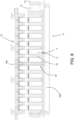
- the supporting base 9 defines a plurality of bays 11 ( Figure 6 ), each of which is configured to house a cell 2 in a respective first predetermined position ( Figure 5 ). Moreover, the bays 11 are defined in such a way as to keep the access port 4 of each cell 2 in a respective second predetermined position. Even the electrical terminals 7 are in respective predetermined positions.
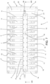
- the supporting base 9 comprises a lower body 12 and a unit 13 for compacting and positioning the cells 2, which is mounted on the lower body 12 ( Figures 6-7 ).
- the compacting and positioning unit 13 comprises two fixed shoulders 14, positioned at the short sides of the lower body 12, between which a plurality of parallel bars 15 extends (four in the accompanying figures, two on each side - Figures 6-7 ).
- Slidingly mounted on the bars 15 is a plurality of spacers 16, each of which has a C shape if seen in plan view.
- the inner part of the C is shaped to match a part of the lateral surface of the main body 17 of the outer case 3 of the cell 2, in order to be able to stably house it.
- Each spacer 16 is also connected to the two spacers 16 which are adjacent to it in such a way that it can be displaced, relative to each of them, between a minimum distance position and a maximum distance position.
- each spacer 16 that is achieved by means of two plates 18, fixed one on each side of the spacer 16, which extend parallel to the bars 15 all in the same direction (all towards the left in the accompanying figures).
- Each plate 18 defines a straight slot 19 which is also parallel to the bars 15, through which there is inserted with play a screw 20 fixed to the adjacent spacer 16. The length of the slot 19 determines the maximum stroke of the relative displacement of the two spacers 16.
- a pressing element 21 is interposed between one of the two shoulders 14 (the right-hand shoulder in Figure 6 and 7 ) and the spacer 16 closest to it.
- the pressing element 21 has a shape substantially similar to that of a main body 17 so that it can be inserted into the C defined by the spacer 16.
- a threaded pin 22 is screwed through the shoulder 14 and acts by pushing on the pressing element 21 to push it towards the other shoulder 14, that is to say, against the closest spacer 16.
- the spacers 16 may be freely displaced relative to each other along the bars 15, it is possible to insert a cell 2 between each pair of adjacent spacers 16. Once all of the cells 2 have been positioned, the threaded pin 22 is acted upon to push the pressing element 21 against the spacer 16, until all of the cells 2 and the spacers 16 are compacted "in a pack", thereby guaranteeing precise and stable positioning of the cells 2.
- the bays 11 are therefore defined by the space located between two adjacent spacers 16 when the whole system is "in a pack".
- the holding member 10 is switchable, relative to the supporting base 9, between a working configuration ( Figures 1-5 , 7-8 ) and a rest configuration (not illustrated).
- the holding member 10 When it is in the working configuration, the holding member 10 is bound to the supporting base 9 above the bays 11 and, in use, prevents the removal of the cells 2 from the bays 11.
- the holding member 10 is advantageously sized in such a way as to leave free access to the terminals 7 of each cell 2 (to allow the forming step to be performed).
- the latter are also advantageously positioned with all of the positive terminals 7 aligned with each other and all of the negative terminals 7 aligned with each other.
- the holding member 10 when it is in the rest configuration, the holding member 10 allows, in use, insertion of the cells 2 into the bays 11 and removal of the cells 2 from the bays 11.
- the holding member 10 when it is in the rest configuration, the holding member 10 is disassociated from the supporting base 9.
- the connection between the holding member 10 and the supporting base 9 is obtained by means of a plurality of screws 23 fixed to the supporting base 9 (in four distinct spacers 16 in the embodiment illustrated - Figure 6 ) which are inserted passing through the holding member 10. Screwed onto the screws 23 there is an enlarged head which is configured to press on the upper part of the holding member 10 (in the embodiment illustrated in the accompanying figures the enlarged head is constituted of a knob 24 - Figures 3-5 ).
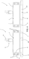
- the device 1 comprises an expansion circuit 25 ( Figures 4 , 9, 11 ) configured to receive, in use, any gaseous substances emitted from the access ports 4 of the cells 2 when the holding member 10 is in the working configuration.
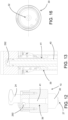
- the expansion circuit 25 comprises a connecting inlet 26 ( Figures 14-15 ) mounted on the holding member 10 and configured to, in use, couple gas-tight to the access port 4 of the cell 2 located in the bay 11 at which the connecting inlet 26 is located, when the holding member 10 is in the working configuration.
- each connecting inlet 26 comprises a nozzle 27 and a sealing gasket 28 ( Figure 14-15 ).
- the nozzle 27 is configured to be inserted in the access port 4, whilst the sealing gasket 28 is configured to be pressed against the outer case 3 of the cell 2, around the access port 4.
- the sealing gasket 28 therefore in use allows the connecting inlet 26 to be connected gas-tight to the access port 4.
- the expansion circuit 25 also comprises one or more expansion chambers 29 and each connecting inlet 26 is fluidly connected with at least one of those expansion chambers 29 in such a way that, in use, any gases created in the inner volume 6 of the cell 2 can freely flow into the one or more expansion chambers 29 through the access ports 4 and the connecting inlets coupled to them.
- each connecting inlet 26 there is a first expansion chamber 291 present which is mounted on the holding member 10 and is fluidly connected with the connecting inlet 26, advantageously directly connected to it ( Figures 10-11 , 14-15 ).
- each first expansion chamber 291 is defined by a tumbler-shaped body 30 that is mounted on the holding member 10 and that has a bottom wall 31 with which the connecting inlet 26 is associated.
- the bottom wall 31 has a funnel shape converging towards the connecting inlet 26, so as to facilitate the return into the cell 2 of any electrolyte liquid that, during the working operations, might come out of the cell 2 in liquid form, or condense in the first expansion chamber 291.
- each first expansion chamber 291 is independent and for the tumbler-shaped body 30 to be closed at the top
- the tumbler-shaped body 30 has an upper wall in which a discharge conduit 32 is made.
- the tumbler-shaped body 30 is slidingly associated with the holding member 10 ( Figure 14 ) and is movable relative to the holding member 10 between a protruding position and a retracted position. In the embodiment illustrated, it is the discharge conduit 32 which is slidingly inserted into a seat 33 made in the holding member 10.
- a sealing gasket 34 is preferably interposed between the tumbler-shaped body 30 and the holding member 10 to guarantee that the first expansion chamber 291 remains gas-tight relative to the outside environment.
- the device 1 also comprises elastic means 35 interposed between the holding member 10 and the tumbler-shaped body 30, which push the tumbler-shaped body 30 towards the protruding position in the absence of other stresses.
- the protruding position is caused by the interaction of a protruding annular shoulder 301 fixed to the tumbler-shaped body 30 with a closing shoulder 48 of the cavity 49 into which the protruding body 30 is inserted in the holding member 10.
- the holding member 10 When the holding member 10 is mounted on the supporting base 9 and is pushed towards the sealed configuration by screwing the knobs 24 on the screws 23, the interaction between the cells 2 and the bottom wall 31 of the tumbler-shaped bodies 30 causes compression of the elastic means 35. Moreover, when the holding member 10 reaches the working configuration, the elastic means 35 allow compensation for any coupling tolerances between each cell 2 and the device 1 in any case guaranteeing sealing.
- At least one collecting chamber 292 present ( Figures 9 , 12-14 ) which is advantageously made in the holding member 10 and which is fluidly connected either with all of the connecting inlets 26, or only with a plurality of connecting inlets 26 (if multiple independent collecting chambers are present, each can only be fluidly connected with one group of connecting inlets 26).
- the expansion circuit 25 further comprises a connecting valve 36 ( Figures 7-11 ), advantageously fluidly connected with the collecting chamber 292, preferably a quick-connect valve.
- a connecting valve 36 ( Figures 7-11 ), advantageously fluidly connected with the collecting chamber 292, preferably a quick-connect valve.
- the connecting valve 36 is connectable to an external suction circuit to allow, in use, an emptying of the one or more expansion chambers 29, by sucking out of the expansion circuit 25 the gases which built up in it as a result of the forming step for the cells 2.
- the connecting valve 36 is connectable to an external pressurised gas supply (inert gas) to allow, in use, a pressurisation of the one or more expansion chambers 29 before proceeding with the forming step for the cells 2.
- the device 1 further comprises at least one pressure transducer 37 mounted in fluid connection with the expansion circuit 25, for measuring the pressure inside the expansion circuit 25.
- the pressure transducer 37 is mounted at one end of the collecting chamber 292, whilst the connecting valve 36 is mounted at the other end ( Figures 5 , 7 , 11 ).
- the pressure transducer 37 comprises an electrical connecting cable 38 which can be connected to an electronic control system for monitoring the pressure trend in the expansion circuit 25 while the forming step is being carried out ( Figure 5 ).
- the expansion circuit 25 advantageously also comprises a connecting conduit 39, that fluidly connects the second expansion chamber 293 with one or more connecting inlets 26 ( Figures 12-14 ).
- the connecting conduit 39 fluidly connects the second expansion chamber 293 with the collecting chamber 292.
- the connecting conduit 39 comprises a first stretch 40 fixed to the supporting base 9, and a second stretch 41 fixed to the holding member 10, which have ends shaped to match each other so that they couple to each other with a male-female connection ( Figure 13 ).
- the device 1 comprises a plurality of expansion chambers 29 all fluidly connected with each other and with all of the connecting inlets 26.
- the device 1 described above is advantageously applied in the context of the method for producing a plurality of lithium battery cells 2 which is the subject matter of this invention, and in particular to implementation of the forming and degassing steps for the cells 2.
- the one disclosed according to this invention comprises firstly, for each cell 2, a sequence of steps performed inside a dry room.
- a pack 42 (previously formed) comprising one or more first electrodes 43 which constitute a cathode of the cell 2, one or more second electrodes 44 which constitute an anode of the cell 2 and one or more separator materials 45 interposed between the first electrodes 43 and the second electrodes 44, is inserted into the main body 17 of the outer case 3 of the cell 2 ( Figures 21 and 25 ).
- the cathode and the anode of the cell 2 are electrically connected to the corresponding electrical terminals 7 mounted on the lid 5 of the outer case 3, similarly to what was described above relative to the prior art.
- the lid 5 also has the access port 4 which passes through it and is open.
- the method then continues with a closing step ( Figure 23 ), during which the lid 5 is fixed fluid-tight to the main body 17 to enclose the pack 42 inside the outer case 3.
- the fluid-tight sealing relates to the connecting zone of the lid 5 to the main body 17 and is advantageously performed by welding.
- the closing step does not affect the access port 4 which is kept open (therefore, the inner volume 6 is not isolated in a sealed fashion from the outside environment).
- a filling step takes place, during which the electrolyte 46 is inserted into the main body 17 through the access port 4.
- the filling step in the known way, is performed in such a way that, at the end, the pack 42 is completely submerged in the electrolyte 46 and that the electrolyte 46 fills the spaces between the different layers which constitute the pack 42 itself ( Figure 24 ).
- the method also comprises carrying out a forming step for the plurality of cells 2 and a cell degassing step.
- a charging voltage is applied between the electrical terminals 7 of each cell 2, according to a predetermined charging time pattern. Due to its intrinsic features, the forming step causes the creation of undesired gases in the inner volume 6 of each cell 2. Such undesired gases are at least partially removed from each cell 2 during the degassing step (advantageously most of the gases are removed).
- the method comprises, again inside the dry room, performing a positioning step, during which each cell 2 of the plurality of cells 2 (advantageously either once the relative filling step has ended, or before performing it) is positioned in one of the bays 11 of a holding and moving device 1 made in accordance with this invention.
- the positioning step is performed while the holding member 10 is in the rest configuration (that is to say, in a configuration similar to that of Figure 6 , where however the spacers are shown in the position that they adopt when they are closed in a pack; in order to be able to insert the cells it is also appropriate to unscrew the threaded pin 22 so as to be able to widen the bays).
- the number of bays 11 is equal to the number of cells 2 which belong to the plurality of cells 2; however, it is also possible to have simultaneous working of a greater number of cells 2, by using multiple devices in parallel.
- An example of that is shown in Figures 17 to 20 , in which the forming step is performed simultaneously on two groups of cells 2 each supported in a device 1 in accordance with this invention, and in which the two devices are moved together by means of a transport pallet 47 (more visible in Figures 1 onwards).
- the method comprises performing a temporary sealing step, during which the holding member 10 is switched from the rest configuration to the working configuration, by connecting the access port 4 of each cell 2 gas-tight to a connecting inlet 26 of the expansion circuit 25.
- the method may preferably comprise performing a pressurisation step, during which an overpressure is created in the one or more expansion chambers 29, relative to the pressure of the surrounding environment.
- an overpressure relative to the pressure of the outside environment will be in the range between 1 mbar and 10 mbar.
- the first displacement step is performed simultaneously for two devices in accordance with this invention, using the above-mentioned transport pallet 47.
- the forming step is performed inside a suitable forming apparatus 50, an embodiment of which can be seen in Figures 17 to 20 .
- the forming apparatus 50 comprises at least one working chamber 51 equipped with a door 52 which can be opened and closed, inside which the working device 1 with all of the cells 2 can be housed (the whole transport pallet 47 with the two working devices in the accompanying figures in which the apparatus 50 also comprises two independent, superposed working chambers 51, the top one open, the bottom one closed).
- positioning of the cells 2 in the transport device 1 causes positioning of all of the electrical terminals 7 in respective predetermined positions. Consequently, by positioning the device 1 in a specific position provided for inside the working chamber 51, the position of the terminals 7 inside the chamber is known and always the same.
- the apparatus 50 also comprises an electrical power supply unit 53 which is movable between a raised position in which it does not interfere with the movement of the device 1 ( Figures 19 and 20 ), and a lowered position.
- the electrical power supply unit 53 comprises a plurality of electrical contacts 54 configured to press against the electrical terminals 7 of the cells 2 when the power supply unit is in the lowered position.
- the electrical contacts 54 are then connected to a voltage supply unit (not illustrated) in such a way that each cell 2 undergoes the required charging pattern.
- the structure of the electrical power supply unit 53 is similar to that of existing electrical power supply units already on the market and is known to a person expert in the sector; therefore, it will not be described in further detail.
- the apparatus 50 may also comprise an electrical connector connectable to the pressure transducer 37 for monitoring the pressure of the gases inside the expansion circuit 25 (not illustrated).
- the apparatus 50 may also comprise a pneumatic connector connectable to the connecting valve 36 for sucking out the gases present inside the expansion circuit 25 (not illustrated).
- the degassing step comprises a passive degassing step and an active degassing step.
- the passive degassing step is implemented at the same time as the forming step.
- at least some of the undesired gases created in each cell 2 expands within the expansion circuit 25 through the access port 4 and the connecting inlet 26 coupled to it. Thanks to the properties of the gases, in order to implement the passive degassing step it is therefore sufficient for the cells 2 to be connected to the expansion circuit 25 and for the creation of undesired gases to occur.
- At least the part of the undesired gases that expanded within the expansion circuit 25 is removed, preferably recovering it for subsequent re-use.
- even the active degassing step is carried out during the forming step, by sucking the gases to be removed through the connecting valve 36.
- the active degassing step is carried out after the forming step, in particular after a second displacement step which is performed after the forming and passive degassing steps, and during which the holding and moving device 1 with the plurality of cells 2 is displaced back into the dry room.
- the method provides for a removal step, performed inside the dry room, during which the holding member 10 is switched to the rest configuration, freeing the access ports 4, and the cells 2 are removed from the bays 11.
- the active degassing step may be performed either before the removal step (by means of the connecting valve 36), or simultaneously with the removal step (for example by performing the latter under an extractor hood).
- the method provides for an electrolyte 46 top-up step if necessary, it its level has dropped too low, and a final sealing step during which the access port 4 of each cell 2 is irreversibly sealed to isolate the inner volume 6 fluid-tight from the outside environment.
- This invention brings important advantages.
Landscapes
- Chemical & Material Sciences (AREA)
- Chemical Kinetics & Catalysis (AREA)
- Electrochemistry (AREA)
- General Chemical & Material Sciences (AREA)
- Engineering & Computer Science (AREA)
- Manufacturing & Machinery (AREA)
- Secondary Cells (AREA)
- Battery Mounting, Suspending (AREA)
Applications Claiming Priority (1)
| Application Number | Priority Date | Filing Date | Title |
|---|---|---|---|
| IT102023000021828A IT202300021828A1 (it) | 2023-10-19 | 2023-10-19 | Dispositivo per il trattenimento e la movimentazione di celle per batterie al litio in fase di realizzazione e metodo per la produzione di una pluralità di celle per batterie al litio che utilizza il dispositivo |
Publications (2)
| Publication Number | Publication Date |
|---|---|
| EP4542702A1 true EP4542702A1 (de) | 2025-04-23 |
| EP4542702B1 EP4542702B1 (de) | 2026-03-25 |
Family
ID=89322158
Family Applications (1)
| Application Number | Title | Priority Date | Filing Date |
|---|---|---|---|
| EP24198601.7A Active EP4542702B1 (de) | 2023-10-19 | 2024-09-05 | Vorrichtung zum halten und bewegen von lithiumbatteriezellen während der herstellung und verfahren zur herstellung einer vielzahl von lithiumbatteriezellen mit der vorrichtung |
Country Status (4)
| Country | Link |
|---|---|
| US (1) | US20250132394A1 (de) |
| EP (1) | EP4542702B1 (de) |
| CA (1) | CA3247850A1 (de) |
| IT (1) | IT202300021828A1 (de) |
Citations (3)
| Publication number | Priority date | Publication date | Assignee | Title |
|---|---|---|---|---|
| US10811720B2 (en) * | 2018-03-30 | 2020-10-20 | Chroma Ate Inc. | Battery cell tray |
| EP3734693A1 (de) * | 2019-01-07 | 2020-11-04 | Lg Chem, Ltd. | Entgasungsvorrichtung, anlage zur herstellung von sekundärbatterien damit und verfahren zur herstellung von sekundärbatterien |
| CN219393656U (zh) * | 2023-04-23 | 2023-07-21 | 宁德时代新能源科技股份有限公司 | 化成注液装置 |
-
2023
- 2023-10-19 IT IT102023000021828A patent/IT202300021828A1/it unknown
-
2024
- 2024-09-05 EP EP24198601.7A patent/EP4542702B1/de active Active
- 2024-10-07 CA CA3247850A patent/CA3247850A1/en active Pending
- 2024-10-18 US US18/919,662 patent/US20250132394A1/en active Pending
Patent Citations (3)
| Publication number | Priority date | Publication date | Assignee | Title |
|---|---|---|---|---|
| US10811720B2 (en) * | 2018-03-30 | 2020-10-20 | Chroma Ate Inc. | Battery cell tray |
| EP3734693A1 (de) * | 2019-01-07 | 2020-11-04 | Lg Chem, Ltd. | Entgasungsvorrichtung, anlage zur herstellung von sekundärbatterien damit und verfahren zur herstellung von sekundärbatterien |
| CN219393656U (zh) * | 2023-04-23 | 2023-07-21 | 宁德时代新能源科技股份有限公司 | 化成注液装置 |
Also Published As
| Publication number | Publication date |
|---|---|
| EP4542702B1 (de) | 2026-03-25 |
| IT202300021828A1 (it) | 2025-04-19 |
| US20250132394A1 (en) | 2025-04-24 |
| CA3247850A1 (en) | 2025-06-02 |
Similar Documents
| Publication | Publication Date | Title |
|---|---|---|
| US9742045B2 (en) | Lithium electrochemical storage battery having a casing providing improved thermal dissipation, associated battery pack and production processes | |
| TWI496335B (zh) | 階梯狀結構之電池單元 | |
| US8752573B2 (en) | Non-aqueous electrolyte secondary battery with filling function, and non-aqueous electrolyte secondary battery and non-aqueous electrolyte filling device used therefor | |
| KR100362552B1 (ko) | 전지의 제조방법 | |
| US20180034107A1 (en) | Electrical energy storage element, method and apparatus for producing said electrical energy storage element | |
| KR20140138674A (ko) | 대형 전기화학 에너지 저장 장치 하우징 및 모듈 | |
| JP2020514989A (ja) | パウチ型二次電池及びパウチフィルム成形装置 | |
| US10896786B2 (en) | Processes and systems for supercapacitor stack fabrication | |
| CN115084803B (zh) | 二次电池的制造方法和二次电池组装体 | |
| IT9067909A1 (it) | Accumulatore ermetico al piombo acido ad elettrodi dipolari. | |
| CN103545543A (zh) | 电化学存储器和用于制造电化学存储器的方法 | |
| EP3096373A1 (de) | Lithiumakkumulator mit flüssigem elektrolyt und verfahren zur herstellung davon | |
| EP4542702B1 (de) | Vorrichtung zum halten und bewegen von lithiumbatteriezellen während der herstellung und verfahren zur herstellung einer vielzahl von lithiumbatteriezellen mit der vorrichtung | |
| CN110828905A (zh) | 一种锂离子电池的制造方法 | |
| EP4113556B1 (de) | Lithium/sodium elektrochemische vorrichtung zur speicherung elektrischer energie in rechteckigen geometrischen zellen | |
| JP2001110401A (ja) | 液体注入方法および液体注入装置 | |
| EP4167330B1 (de) | Sekundärbatterie und verfahren zur herstellung | |
| CN214203774U (zh) | 电池模组和电池 | |
| WO2025138925A1 (zh) | 密封性检测装置以及电池单体的制造设备 | |
| CN113381119B (zh) | 一种电池制作方法以及电池 | |
| CN115939547A (zh) | 电池单体检漏方法及电池单体检漏前处理设备 | |
| CN114388870B (zh) | 一种软包电池单体以及软包电池模组 | |
| JP2019121461A (ja) | 注液装置及び蓄電モジュールの製造方法 | |
| JP2004134203A (ja) | 組電池 | |
| CN223718759U (zh) | 一种装配机构、阀组件及电池生产设备 |
Legal Events
| Date | Code | Title | Description |
|---|---|---|---|
| PUAI | Public reference made under article 153(3) epc to a published international application that has entered the european phase |
Free format text: ORIGINAL CODE: 0009012 |
|
| STAA | Information on the status of an ep patent application or granted ep patent |
Free format text: STATUS: THE APPLICATION HAS BEEN PUBLISHED |
|
| AK | Designated contracting states |
Kind code of ref document: A1 Designated state(s): AL AT BE BG CH CY CZ DE DK EE ES FI FR GB GR HR HU IE IS IT LI LT LU LV MC ME MK MT NL NO PL PT RO RS SE SI SK SM TR |
|
| STAA | Information on the status of an ep patent application or granted ep patent |
Free format text: STATUS: REQUEST FOR EXAMINATION WAS MADE |
|
| 17P | Request for examination filed |
Effective date: 20250529 |
|
| GRAP | Despatch of communication of intention to grant a patent |
Free format text: ORIGINAL CODE: EPIDOSNIGR1 |
|
| STAA | Information on the status of an ep patent application or granted ep patent |
Free format text: STATUS: GRANT OF PATENT IS INTENDED |
|
| INTG | Intention to grant announced |
Effective date: 20251112 |
|
| GRAS | Grant fee paid |
Free format text: ORIGINAL CODE: EPIDOSNIGR3 |
|
| GRAA | (expected) grant |
Free format text: ORIGINAL CODE: 0009210 |
|
| STAA | Information on the status of an ep patent application or granted ep patent |
Free format text: STATUS: THE PATENT HAS BEEN GRANTED |
|
| AK | Designated contracting states |
Kind code of ref document: B1 Designated state(s): AL AT BE BG CH CY CZ DE DK EE ES FI FR GB GR HR HU IE IS IT LI LT LU LV MC ME MK MT NL NO PL PT RO RS SE SI SK SM TR |
|
| REG | Reference to a national code |
Ref country code: CH Ref legal event code: F10 Free format text: ST27 STATUS EVENT CODE: U-0-0-F10-F00 (AS PROVIDED BY THE NATIONAL OFFICE) Effective date: 20260325 Ref country code: GB Ref legal event code: FG4D |
|
| REG | Reference to a national code |
Ref country code: DE Ref legal event code: R096 Ref document number: 602024003428 Country of ref document: DE |
|
| REG | Reference to a national code |
Ref country code: IE Ref legal event code: FG4D |