EP4542182A1 - Measurement method and measurement device for remaining quantity of liquid in liquid storage container - Google Patents
Measurement method and measurement device for remaining quantity of liquid in liquid storage container Download PDFInfo
- Publication number
- EP4542182A1 EP4542182A1 EP23850273.6A EP23850273A EP4542182A1 EP 4542182 A1 EP4542182 A1 EP 4542182A1 EP 23850273 A EP23850273 A EP 23850273A EP 4542182 A1 EP4542182 A1 EP 4542182A1
- Authority
- EP
- European Patent Office
- Prior art keywords
- liquid
- storage container
- remaining amount
- liquid storage
- ultrasonic
- Prior art date
- Legal status (The legal status is an assumption and is not a legal conclusion. Google has not performed a legal analysis and makes no representation as to the accuracy of the status listed.)
- Pending
Links
Images


Classifications
-
- G—PHYSICS
- G01—MEASURING; TESTING
- G01F—MEASURING VOLUME, VOLUME FLOW, MASS FLOW OR LIQUID LEVEL; METERING BY VOLUME
- G01F23/00—Indicating or measuring liquid level or level of fluent solid material, e.g. indicating in terms of volume or indicating by means of an alarm
- G01F23/22—Indicating or measuring liquid level or level of fluent solid material, e.g. indicating in terms of volume or indicating by means of an alarm by measuring physical variables, other than linear dimensions, pressure or weight, dependent on the level to be measured, e.g. by difference of heat transfer of steam or water
- G01F23/28—Indicating or measuring liquid level or level of fluent solid material, e.g. indicating in terms of volume or indicating by means of an alarm by measuring physical variables, other than linear dimensions, pressure or weight, dependent on the level to be measured, e.g. by difference of heat transfer of steam or water by measuring the variations of parameters of electromagnetic or acoustic waves applied directly to the liquid or fluent solid material
- G01F23/296—Acoustic waves
-
- G—PHYSICS
- G01—MEASURING; TESTING
- G01F—MEASURING VOLUME, VOLUME FLOW, MASS FLOW OR LIQUID LEVEL; METERING BY VOLUME
- G01F23/00—Indicating or measuring liquid level or level of fluent solid material, e.g. indicating in terms of volume or indicating by means of an alarm
- G01F23/22—Indicating or measuring liquid level or level of fluent solid material, e.g. indicating in terms of volume or indicating by means of an alarm by measuring physical variables, other than linear dimensions, pressure or weight, dependent on the level to be measured, e.g. by difference of heat transfer of steam or water
- G01F23/28—Indicating or measuring liquid level or level of fluent solid material, e.g. indicating in terms of volume or indicating by means of an alarm by measuring physical variables, other than linear dimensions, pressure or weight, dependent on the level to be measured, e.g. by difference of heat transfer of steam or water by measuring the variations of parameters of electromagnetic or acoustic waves applied directly to the liquid or fluent solid material
- G01F23/284—Electromagnetic waves
- G01F23/292—Light, e.g. infrared or ultraviolet
-
- G—PHYSICS
- G01—MEASURING; TESTING
- G01F—MEASURING VOLUME, VOLUME FLOW, MASS FLOW OR LIQUID LEVEL; METERING BY VOLUME
- G01F23/00—Indicating or measuring liquid level or level of fluent solid material, e.g. indicating in terms of volume or indicating by means of an alarm
- G01F23/22—Indicating or measuring liquid level or level of fluent solid material, e.g. indicating in terms of volume or indicating by means of an alarm by measuring physical variables, other than linear dimensions, pressure or weight, dependent on the level to be measured, e.g. by difference of heat transfer of steam or water
- G01F23/28—Indicating or measuring liquid level or level of fluent solid material, e.g. indicating in terms of volume or indicating by means of an alarm by measuring physical variables, other than linear dimensions, pressure or weight, dependent on the level to be measured, e.g. by difference of heat transfer of steam or water by measuring the variations of parameters of electromagnetic or acoustic waves applied directly to the liquid or fluent solid material
- G01F23/284—Electromagnetic waves
- G01F23/292—Light, e.g. infrared or ultraviolet
- G01F23/2921—Light, e.g. infrared or ultraviolet for discrete levels
-
- G—PHYSICS
- G01—MEASURING; TESTING
- G01F—MEASURING VOLUME, VOLUME FLOW, MASS FLOW OR LIQUID LEVEL; METERING BY VOLUME
- G01F23/00—Indicating or measuring liquid level or level of fluent solid material, e.g. indicating in terms of volume or indicating by means of an alarm
- G01F23/80—Arrangements for signal processing
-
- G—PHYSICS
- G01—MEASURING; TESTING
- G01N—INVESTIGATING OR ANALYSING MATERIALS BY DETERMINING THEIR CHEMICAL OR PHYSICAL PROPERTIES
- G01N15/00—Investigating characteristics of particles; Investigating permeability, pore-volume or surface-area of porous materials
- G01N15/02—Investigating particle size or size distribution
- G01N15/0205—Investigating particle size or size distribution by optical means
-
- G—PHYSICS
- G01—MEASURING; TESTING
- G01N—INVESTIGATING OR ANALYSING MATERIALS BY DETERMINING THEIR CHEMICAL OR PHYSICAL PROPERTIES
- G01N15/00—Investigating characteristics of particles; Investigating permeability, pore-volume or surface-area of porous materials
- G01N15/02—Investigating particle size or size distribution
- G01N15/0205—Investigating particle size or size distribution by optical means
- G01N15/0227—Investigating particle size or size distribution by optical means using imaging; using holography
-
- G—PHYSICS
- G01—MEASURING; TESTING
- G01N—INVESTIGATING OR ANALYSING MATERIALS BY DETERMINING THEIR CHEMICAL OR PHYSICAL PROPERTIES
- G01N15/00—Investigating characteristics of particles; Investigating permeability, pore-volume or surface-area of porous materials
- G01N15/06—Investigating concentration of particle suspensions
- G01N15/075—Investigating concentration of particle suspensions by optical means
-
- G—PHYSICS
- G06—COMPUTING OR CALCULATING; COUNTING
- G06N—COMPUTING ARRANGEMENTS BASED ON SPECIFIC COMPUTATIONAL MODELS
- G06N20/00—Machine learning
-
- G—PHYSICS
- G01—MEASURING; TESTING
- G01F—MEASURING VOLUME, VOLUME FLOW, MASS FLOW OR LIQUID LEVEL; METERING BY VOLUME
- G01F22/00—Methods or apparatus for measuring volume of fluids or fluent solid material, not otherwise provided for
-
- G—PHYSICS
- G01—MEASURING; TESTING
- G01N—INVESTIGATING OR ANALYSING MATERIALS BY DETERMINING THEIR CHEMICAL OR PHYSICAL PROPERTIES
- G01N15/00—Investigating characteristics of particles; Investigating permeability, pore-volume or surface-area of porous materials
- G01N2015/0007—Investigating dispersion of gas
- G01N2015/0011—Investigating dispersion of gas in liquids, e.g. bubbles
-
- Y—GENERAL TAGGING OF NEW TECHNOLOGICAL DEVELOPMENTS; GENERAL TAGGING OF CROSS-SECTIONAL TECHNOLOGIES SPANNING OVER SEVERAL SECTIONS OF THE IPC; TECHNICAL SUBJECTS COVERED BY FORMER USPC CROSS-REFERENCE ART COLLECTIONS [XRACs] AND DIGESTS
- Y02—TECHNOLOGIES OR APPLICATIONS FOR MITIGATION OR ADAPTATION AGAINST CLIMATE CHANGE
- Y02E—REDUCTION OF GREENHOUSE GAS [GHG] EMISSIONS, RELATED TO ENERGY GENERATION, TRANSMISSION OR DISTRIBUTION
- Y02E60/00—Enabling technologies; Technologies with a potential or indirect contribution to GHG emissions mitigation
- Y02E60/10—Energy storage using batteries
Definitions
- the present invention relates to a method and apparatus for measuring a remaining amount of liquid in a liquid storage container, and more particularly, to a method and apparatus for measuring a remaining amount of liquid in a liquid storage container, which are capable of more accurately and quickly estimating and identifying the remaining amount of liquid in the liquid storage container that is difficult to visually check the inside thereof.
- Secondary batteries which are widely used in various digital devices and transport means such as vehicles are repeatedly chargeable and dischargeable. Also, research and development are continuously performed to increase efficiency and improve safety.
- a secondary battery is manufactured in structure in which an electrode assembly, in which a positive electrode/separator/negative electrode are repeatedly stacked, is accommodated in a case such as a can or pouch, and then, an electrolyte is injected into the case.
- FIG. 1 which illustrates a cross-sectional view of an electrolyte being discharged from a liquid storage container
- the liquid storage container 1 is provided in a cylindrical shape having a bottom surface 1a, a circumferential wall 1b, and a top surface 1c, and in a state of standing vertically, when a suction tube 3 enters through a hole defined in the top surface 1c, and a negative pressure is applied to the suction tube 3, an electrolyte l is discharged to the outside of the liquid storage container 1.
- the liquid storage container 1 in which the electrolyte is stored is made of stainless steel.
- a remaining amount of electrolyte inside the liquid storage container i.e., a height of a water surface s, from the outside.
- an internal pressure of the liquid storage container l increases to inject an inert gas g into the liquid storage container 1 through a gas injection tube 2 during discharging of the electrolyte or when the discharge of the electrolyte is almost finished so as to minimize a remaining amount of electrolyte.
- an injection of a gas g may start when the water surface s of the electrolyte l falls below a certain reference, and when the water surface s of the electrolyte falls below the suction tube 3, it is preferable that the injection of the gas g is stopped, but when a time point at which the injection of the gas g starts is too early, and a time point at which the injection g of the gas is stopped is too late, there is a problem that bubbles P (see FIG. 2 ) are introduced together into the suction tube 3.
- the bubbles cause defects of the secondary battery. That is, when a small amount of electrolyte remains, the gas g is injected to ensure smooth discharge of the electrolyte into the liquid storage container, but when the gas g is introduced into the suction tube 3, a motor or pump and the suction tube, which generates the negative pressure in the suction tube 3, are connected to the suction tube to cause idling of the motor or pump, which injects the electrolyte into the case of the secondary battery, thereby causing malfunction, and when the gas g introduced together with the electrolyte is introduced together with the case of the secondary battery, a swelling phenomenon occurs in the secondary battery in the future.
- a main object of the present invention is to provide a method and apparatus for measuring a remaining amount of liquid within a liquid storage container, which are capable of quickly and accurately estimating or measuring the remaining amount of electrolyte within the liquid storage container to satisfy the above technical needs.
- the 'measurement' described here is used not only to measure the remaining amount of electrolyte (liquid), but also to predict and estimate how much electrolyte remains in the liquid storage container or whether the remaining amount has fallen below a predetermined standard value.
- the present invention for achieving the above-mentioned object includes a method and apparatus for measuring a remaining amount of liquid in a liquid storage container.
- the present invention provides a configuration for estimating (predicting or measuring) the remaining amount by monitoring bubbles contained in the discharged liquid (electrolyte) and provides an additional configuration capable of being accomplished together with or separately from the above configuration, i.e., a configuration that oscillates ultrasonic waves inside the liquid storage container to estimate (predict or measure) the remaining amount based on the waveform of the ultrasonic carrier wave.
- a light transmitting part is provided in the suction tube to observe characteristics of the bubbles through the light transmitting part and estimate the remaining amount of electrolyte based on the observed characteristics, and in the present invention, the measuring method and measuring apparatus having these technical features are provided as examples.
- a method for measuring a remaining amount of a liquid within a liquid storage container includes: discharging the liquid within the liquid storage container to the outside through a suction tube inserted into the liquid storage container; observing a size of a bubble or the number of bubbles contained in the liquid passing through the light transmitting part through a vision device that emits light toward the light transmitting part of the suction tube; and estimating the remaining amount of liquid based on the size and number of observed bubbles.
- the method may further include injecting a gas into the liquid storage container after discharging the liquid within a predetermined range.
- the liquid may be an electrolyte for a secondary battery, and the gas injected into the liquid storage container may be nitrogen.
- the method may further include, when it is estimated that the estimated remaining amount of liquid is less than a predetermined remaining amount, stopping the injection of the gas into the liquid storage container.
- light may be emitted from the lighting toward the light transmitting part.
- a controller configured to estimate the remaining amount of liquid based on information received from the vision device may estimate the remaining amount of liquid in a machine learning manner in which a correlation between the size and number of observed bubbles and an actual amount of liquid remaining is learned to estimate the remaining amount based on the learned data.
- controller configured to estimate the remaining amount of liquid based on information received from the vision device may compare the size and number of observed bubbles to previously provided reference data to estimate the remaining amount of liquid.
- the method may further include estimating the remaining amount using an ultrasonic carrier wave.
- the estimating of the remaining amount using the ultrasonic carrier wave may include: oscillating ultrasonic waves from an ultrasonic generator to the inside of the liquid storage container; receiving the ultrasonic waves returned after the oscillation to analyze a waveform of the ultrasonic waves; and comparing the waveform of the ultrasonic waves to previously provided reference data to estimate the remaining amount of liquid.
- the ultrasonic generator may be in close contact with a center of an outer surface of the bottom of the liquid storage container or be in close contact with a circumferential wall of the liquid storage container.
- the estimating of the remaining amount using the ultrasonic carrier wave may be performed before the discharging of the liquid within the liquid storage container to the outside through the suction tube or after the estimating of the remaining amount of liquid through the size and number of observed bubbles.
- the present invention provides a measuring apparatus capable of measuring a remaining amount by determining a state of bubbles as described above.
- An apparatus for measuring a remaining amount of liquid within a liquid storage container which is provided in the present invention, includes: a liquid storage container in which a liquid is stored; a suction tube which is connected to the liquid storage container, through which the liquid is suctioned and discharged, and which is provided with a light transmitting part made of a transparent or translucent material; a vision device directed to the light transmitting part; and a controller configured to receive information about a size and number of bubbles from the vision device so as to estimate the remaining amount of liquid.
- the controller may be configured to output the information on the size and number of bubbles, which is received from the vision device, and the estimation results on a display device.
- the apparatus may further include a lighting configured to emit light toward the light transmitting part.
- the light transmitting part may be disposed in a predetermined section in the suction tube and be disposed in a section extending in a straight line from the outside the liquid storage container.
- the present invention provides a measuring method and apparatus in which ultrasonic waves are oscillated to estimate a remaining amount based on a waveform of an ultrasonic carrier wave.
- a method for measuring a remaining amount of liquid within a liquid storage container includes: closely attaching an ultrasonic generator generating ultrasonic waves to an outer surface of the liquid storage container; oscillating the ultrasonic waves from the ultrasonic generator to the inside of the liquid storage container; receiving the ultrasonic waves returned after the oscillation to analyze a waveform of the ultrasonic waves; and comparing the waveform of the ultrasonic waves to previously provided reference data to estimate the remaining amount of liquid.
- An apparatus for measuring a remaining amount of liquid within the liquid storage container includes: a liquid storage container in which a liquid is stored; an ultrasonic generator attached to an outer surface of the liquid storage container to oscillate ultrasonic waves toward the inside of the liquid storage container; an ultrasonic receiver configured to receive the ultrasonic waves returned after being generated from the ultrasonic generator; and a controller configured to estimate the remaining amount of liquid by comparing waveform information of the ultrasonic waves received from the ultrasonic receiver to previously provided reference data.
- the ultrasonic receiver may be integrated with the ultrasonic generator, and the ultrasonic generator may be configured to oscillate the ultrasonic waves, receive the returned ultrasonic waves, and transmits waveform information of the received ultrasonic waves to the controller.
- the ultrasonic generator may be attached to a center of an outer surface of the bottom of the liquid storage container or be attached to a circumferential wall of the liquid storage container.
- the present invention having the above configuration may determine the remaining amount of liquid (electrolyte) in the liquid storage container in real time, and thus, the input and stop time points and an input amount of gas injected into the liquid storage container may be more accurately determined to solve the conventional problem in which the motor and the pump malfunction, and the bubbles are introduced together into the case of the secondary battery.
- the remaining amount may be estimated by observing the size and number of bubbles passing through the suction tube so as not to affect the flow speed of the electrolyte and not to cause the physical and/or chemical changes or impacts to the electrolyte.
- the inflow of the foreign substances may be blocked fundamentally.
- the additional light may be irradiated from the lighting to observe the size and number of bubbles through the more accurate image data.
- the controller may more quickly estimate the remaining amount of liquid by comparing the size and number of observed bubbles to the previously provided reference data.
- the controller may estimate the remaining amount of liquid using the machine learning method that learns by comparing and analyzing the correlation between the size and number of observed bubbles and the actual remaining amount of liquid and estimates the remaining amount of liquid based on the learned data, and thus, even when the physical properties are changed, or the size of the liquid storage container is changed, the remaining amount of liquid may be estimated in consideration of the variables.
- the remaining amount of electrolyte may be estimated using the ultrasonic carrier wave. Therefore, the remaining amount of electrolyte may be more accurately measured by performing the method for estimating the remaining amount by observing the bubbles.
- the present invention relates to a method and apparatus for measuring a remaining amount of electrolyte l in a liquid storage container 10.
- the present invention provides a configuration for estimating a remaining amount by monitoring bubbles P contained in a discharged liquid electrolyte as a first embodiment and provides an additional configuration that is performed together with the first embodiment or performed separately from the first embodiment, i.e., a configuration that oscillates ultrasonic waves into a liquid storage container and estimates the remaining amount based on the waveform of the ultrasonic carrier wave as a second embodiment.
- the present invention provides a method and apparatus for estimating a remaining amount by monitoring bubbles P contained in a discharged electrolyte l as a first embodiment.
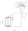
- FIG. 2 is a view illustrating a state in which a vision device 40 and a lighting 41 are disposed to observe a size and number of bubbles P through a light transmitting part 31 of a suction tube 30, and the vision device 40 is connected to a controller 50.
- an apparatus for measuring a remaining amount of a liquid in a liquid storage container includes a liquid storage container 10 in which a liquid is stored, a suction tube 30, a vision device 40, and a controller 50.
- the liquid storage container 10 has a cylindrical shape with a bottom surface 10a, a circumferential wall 10b standing vertically along a circumference of the bottom surface 10a, and a top surface 10c covering an opened upper side of the circumferential wall 10b.
- at least two holes are punched in the top surface 10c, and a gas injection tube 20 through which a gas g is injected into the liquid storage container and a suction tube 30 through which an electrolyte is suctioned from the liquid storage container 10 and then is discharged to the outside are coupled to the holes, respectively.
- the gas injection tube 20 does not protrude into the liquid storage container 10 or protrudes only by a small length, but the suction tube 30 has an end disposed close to the bottom surface 10a to maximize suction of the electrolyte stored in the liquid storage container 10.
- the bottom surface 10a may be provided as a spherical surface, and the end of the suction tube 30 may be disposed as low as possible at a slight distance from a center of the spherical surface.
- one side of the suction tube 30 is placed on the bottom surface 10a inside the liquid storage container 10, and the other side of the suction tube 30 is connected to a separate storage facility or an injection device for injecting the electrolyte to suction the electrolyte l stored in the liquid storage container 10 and then allow the electrolyte 1 to move to the storage facility or the injection device.
- the suction tube 30 is provided with a light transmitting part 31 made of a transparent or translucent material (preferably made of a transparent material) at a portion that is spaced apart from the liquid storage container 10 so as to be exposed to the outside.
- a light transmitting part 31 made of a transparent or translucent material (preferably made of a transparent material) at a portion that is spaced apart from the liquid storage container 10 so as to be exposed to the outside.
- the light transmitting part 31 may be disposed in a predetermined section of the suction tube 30, but may be disposed not only at one position but at two or more positions spaced apart from each other.
- the position is not particularly limited, but is disposed in a section extending in a straight line from the outside the liquid storage container 10 so that more accurate optical information is obtained when the vision device 40 optically senses the bubbles P.
- the vision device 40 may use a camera, an optical sensor, and the like, which are capable of obtaining an optical image or an image having the number and/or size of bubbles P contained in the electrolyte to move together while the electrolyte moves.
- the vision device 40 transmits the acquired image information to the controller 50.
- the lighting 41 that emits light toward the light transmitting part 31 may be added according to lighting conditions around the light transmitting part 31.
- the image information about the size and number of bubbles P transmitted from the vision device 40 is transmitted to the controller 50, and then, the controller 50 analyzes the received image information to estimate a remaining amount of electrolyte inside the liquid storage container 10 or a height of a water surface S of the electrolyte. That is, when the water surface S of the electrolyte l falls below the end of the suction tube 30, air and gas g together with the electrolyte are suctioned into the suction tube 30. Here, the air and gas g pass through the light transmitting part 31 in the form of bubbles P while the electrolyte flows. Thus, the height of the water surface S of the electrolyte may be estimated through the size and number of bubbles P, and thus, the remaining amount may also be estimated.
- the measuring apparatus has a configuration, in which a portion of the suction tube 30 is transparent to provide the light transmitting part 31, and the state of the bubbles P is determined through the light transmitting part 31 to estimate the remaining amount.
- sensing performance may be improved by additionally irradiating the light 41 or increasing in resolution of the captured image.
- the controller 50 may be configured to output the information on the size and number of bubbles, which is received from the vision device 40, and the estimation results on a display device (not shown) so that a worker and manager determine the remaining amount and the measurement states.
- the controller 50 may be configured to compare the size and number of observed bubbles to previously provided reference data so as to estimate the remaining amount of liquid (electrolyte).
- the controller may be configured to estimate the remaining amount of liquid in a machine learning manner in which the correlation between the size and number of observed bubbles and an actual remaining amount of liquid is compared and analyzed to be learned, and then, the remaining amount is estimated based on the learned data.
- This embodiment provides a measuring method using the measuring apparatus having the above configuration.
- a method for measuring the remaining amount of liquid in the liquid storage container 10 provided in this embodiment begins with a process of discharging an electrolyte stored in a liquid storage container to the outside through a suction tube 30.
- a light transmitting part 31 is provided on the suction tube 30 so that a vision device 40 performs a process of observing (sensing) a size of bubble P or the number of bubbles P, which are contained in the electrolyte passing through the light transmitting part 31.
- a process of injecting a gas g into the liquid storage container after discharging the liquid within a predetermined range according to the remaining amount, i.e., the number of bubbles may be additionally performed.
- the liquid is an electrolyte for a secondary battery
- the gas injected into the liquid storage container is nitrogen, which does not chemically react with the electrolyte.
- the present invention provides a measuring method and apparatus in which ultrasonic waves are oscillated to estimate a remaining amount based on a waveform of an ultrasonic carrier wave as a second embodiment.
- the method using the ultrasonic carrier wave according to the second embodiment may be performed simultaneously with the measuring method according to the first embodiment or performed separately before and after the measuring method according to the first embodiment or performed instead of the measuring method according to the first embodiment.
- FIG. 3 is a view illustrating a state in which an ultrasonic generator 60 is attached to an outer bottom surface of the liquid storage container and is connected to the controller
- FIG. 4 is a view illustrating a state in which the ultrasonic generator 60 is attached to an outer circumferential wall 10b of the liquid storage container and is connected to the controller.
- FIG. 5 is a view illustrating a state in which a vision device 40 and a lighting 41 are disposed to observe the size and number of bubbles through a light transmitting part 31 of a suction tube 30, the ultrasonic generator 60 is attached to the bottom surface 10a of the liquid storage container 10, and each of the vision device and the ultrasonic generator is connected to the same one controller 50.
- the apparatus for measuring a remaining amount of liquid within the liquid storage container 10 includes the ultrasonic generator 60 attached to an outer surface (bottom surface or circumferential wall) of the liquid storage container in which a liquid is stored to oscillate ultrasonic waves toward the inside of the liquid storage container, an ultrasonic receiver (not shown) that receives the ultrasonic waves returned after being generated from the ultrasonic generator 60, and the controller 50 that estimates the remaining amount of liquid by comparing waveform information of the ultrasonic waves received from the ultrasonic receiver to previously provided reference data.
- the controller 50 may be the controller 50 provided in the first embodiment or may be provided separately.
- 'carrier wave u1 reflected from a water surface S of an electrolyte l' and 'carrier wave u2 reflected from an inner wall (top surface, circumferential, etc.) of the liquid storage container 10 after passing through the water surface S of the electrolyte l' have amplitudes, phases, frequencies, periods, etc., which are different from each other, to vary in waveform. That is, the ultrasonic waves react differently when passing through a liquid medium and when passing through a gaseous (air) medium, resulting in varying in waveform.
- a height of the water surface s of the electrolyte may be determined through a difference in waveform of the carrier waves u1 and u2 or a change in characteristic of a carrier wave u3 according to mounted positions of the ultrasonic generator 60.
- the ultrasonic receiver may be integrated with the ultrasonic generator 60, and the ultrasonic generator 60 may oscillate ultrasonic waves and receive the returned ultrasonic waves to transmit waveform information of the received ultrasonic waves to the controller 50.
- the ultrasonic generator 60 may be attached to a center from the outside of the bottom surface 10a of the liquid storage container 10 as illustrated in FIGS. 3 and 5 or may be attached to the circumferential wall 10b of the liquid storage container 10a as illustrated in FIG. 4 .
- this embodiment provides a measurement method using the measuring apparatus having the above configuration.
- a method for measuring a remaining amount of liquid within a liquid storage container using ultrasonic waves includes a process of closely attaching an ultrasonic generator 60 generating ultrasonic waves to an outer surface of a liquid storage container, a process of oscillating the ultrasonic waves from the ultrasonic generator 60 to the inside of the liquid storage container 10, a process of receiving the ultrasonic waves returned after the oscillation to analyze the waveform of the ultrasonic waves, and a process of comparing the waveform of the ultrasonic waves to previously provided reference data to estimate the remaining amount of liquid.
- the ultrasonic receiver may be integrated into the ultrasonic generator, and two or more ultrasonic receivers may be attached to the liquid storage container to further improve estimation accuracy by individually analyzing the waveform of the ultrasonic waves at different points.
- the ultrasonic generator with which the ultrasonic receiver is integrated may be in close contact with a center at the outside of a bottom surface 10a of the liquid storage container and may also be in close contact with a circumferential wall 10b of the liquid storage container.
- the process of estimating the remaining amount using carrier waves of the ultrasonic waves may be performed before a process of discharging the liquid in the liquid storage container to the outside through the suction tube 30 or after a process of estimating the remaining amount of liquid through a size and number of observed bubbles.
- the apparatus for measuring the remaining amount using the ultrasonic waves provided in the second embodiment may be installed together with the apparatus for measuring the remaining amount provided in the first embodiment, as illustrated in FIG. 5 .
- the method of measuring the remaining amount using the ultrasonic waves provided in the second embodiment may be performed simultaneously with the method of measuring the remaining amount provided in the first embodiment or may be performed sequentially with a time difference.
- the controller 50 may be configured to be connected to a vision device 40, an ultrasonic generator 60, and an ultrasonic receiver to receive all of ultrasonic waveform information and bubble information, thereby finally estimating the remaining amount by synthesizing the two pieces of information.
- only one of the method for measuring the remaining amount provided in the first embodiment and the method for measuring the remaining amount provided in the second embodiment may be implemented.
- the present invention having the above configuration may determine the remaining amount of liquid (electrolyte) in the liquid storage container in real time, and thus, the input and stop time points and an input amount of gas injected into the liquid storage container may be more accurately determined to solve the conventional problem in which the motor and the pump are malfunctioned, and the bubbles are introduced together into the case of the secondary battery.
- the remaining amount may be estimated by observing the size and number of bubbles passing through the suction tube so as not to affect the flow speed of the electrolyte and not to cause the physical and/or chemical changes or impacts to the electrolyte.
- the inflow of the foreign substances may be blocked fundamentally.
- the additional light may be irradiated from the lighting to observe the size and number of bubbles through the more accurate image data.
- the controller may more quickly estimate the remaining amount of liquid by comparing the size and number of observed bubbles to the previously provided reference data.
- the controller may estimate the remaining amount of liquid using the machine learning method that learns by comparing and analyzing the correlation between the size and number of observed bubbles and the actual remaining amount of liquid and estimates the remaining amount of liquid based on the learned data, and thus, even when the physical properties are changed, or the size of the liquid storage container is changed, the remaining amount of liquid may be estimated in consideration of the variables.
- the remaining amount of electrolyte may be estimated using the ultrasonic carrier wave. Therefore, the remaining amount of electrolyte may be more accurately measured by performing the method for estimating the remaining amount by observing the bubbles.
Landscapes
- Physics & Mathematics (AREA)
- General Physics & Mathematics (AREA)
- Engineering & Computer Science (AREA)
- Electromagnetism (AREA)
- Chemical & Material Sciences (AREA)
- Fluid Mechanics (AREA)
- Theoretical Computer Science (AREA)
- Software Systems (AREA)
- Thermal Sciences (AREA)
- Dispersion Chemistry (AREA)
- Analytical Chemistry (AREA)
- Biochemistry (AREA)
- General Health & Medical Sciences (AREA)
- Immunology (AREA)
- Pathology (AREA)
- Life Sciences & Earth Sciences (AREA)
- Health & Medical Sciences (AREA)
- Data Mining & Analysis (AREA)
- Computer Vision & Pattern Recognition (AREA)
- Evolutionary Computation (AREA)
- Medical Informatics (AREA)
- Artificial Intelligence (AREA)
- Computing Systems (AREA)
- General Engineering & Computer Science (AREA)
- Mathematical Physics (AREA)
- Acoustics & Sound (AREA)
- Signal Processing (AREA)
- Filling, Topping-Up Batteries (AREA)
- Measurement Of Levels Of Liquids Or Fluent Solid Materials (AREA)
Abstract
Description
- The present application claims the benefit of the priority of
Korean Patent Application No. 10-2022-0095708, filed on August 1, 2022 - The present invention relates to a method and apparatus for measuring a remaining amount of liquid in a liquid storage container, and more particularly, to a method and apparatus for measuring a remaining amount of liquid in a liquid storage container, which are capable of more accurately and quickly estimating and identifying the remaining amount of liquid in the liquid storage container that is difficult to visually check the inside thereof.
- Secondary batteries, which are widely used in various digital devices and transport means such as vehicles are repeatedly chargeable and dischargeable. Also, research and development are continuously performed to increase efficiency and improve safety.
- A secondary battery is manufactured in structure in which an electrode assembly, in which a positive electrode/separator/negative electrode are repeatedly stacked, is accommodated in a case such as a can or pouch, and then, an electrolyte is injected into the case.
- The electrolyte is injected into a liquid storage container such as a drum and then is stored and moves. In addition, as illustrated in
FIG. 1 , which illustrates a cross-sectional view of an electrolyte being discharged from a liquid storage container, theliquid storage container 1 is provided in a cylindrical shape having abottom surface 1a, acircumferential wall 1b, and atop surface 1c, and in a state of standing vertically, when asuction tube 3 enters through a hole defined in thetop surface 1c, and a negative pressure is applied to thesuction tube 3, an electrolyte l is discharged to the outside of theliquid storage container 1. - However, in order to maintain physical and chemical stability of the electrolyte l, the
liquid storage container 1 in which the electrolyte is stored is made of stainless steel. Thus, there is a problem that it is difficult to visually check a remaining amount of electrolyte inside the liquid storage container, i.e., a height of a water surface s, from the outside. - In the related art, an internal pressure of the liquid storage container l increases to inject an inert gas g into the
liquid storage container 1 through agas injection tube 2 during discharging of the electrolyte or when the discharge of the electrolyte is almost finished so as to minimize a remaining amount of electrolyte. - However, an injection of a gas g may start when the water surface s of the electrolyte l falls below a certain reference, and when the water surface s of the electrolyte falls below the
suction tube 3, it is preferable that the injection of the gas g is stopped, but when a time point at which the injection of the gas g starts is too early, and a time point at which the injection g of the gas is stopped is too late, there is a problem that bubbles P (seeFIG. 2 ) are introduced together into thesuction tube 3. - In addition, when the electrolyte is injected into the case of the secondary battery (such as measuring an amount of electrolyte injection), the bubbles cause defects of the secondary battery. That is, when a small amount of electrolyte remains, the gas g is injected to ensure smooth discharge of the electrolyte into the liquid storage container, but when the gas g is introduced into the
suction tube 3, a motor or pump and the suction tube, which generates the negative pressure in thesuction tube 3, are connected to the suction tube to cause idling of the motor or pump, which injects the electrolyte into the case of the secondary battery, thereby causing malfunction, and when the gas g introduced together with the electrolyte is introduced together with the case of the secondary battery, a swelling phenomenon occurs in the secondary battery in the future. - Thus, in order to prevent the inflow of the bubbles P and waste of the electrolyte, a technical need is required for measuring the remaining amount in the
liquid storage container 1 in which the electrolyte is stored. - A main object of the present invention is to provide a method and apparatus for measuring a remaining amount of liquid within a liquid storage container, which are capable of quickly and accurately estimating or measuring the remaining amount of electrolyte within the liquid storage container to satisfy the above technical needs. For reference, the 'measurement' described here is used not only to measure the remaining amount of electrolyte (liquid), but also to predict and estimate how much electrolyte remains in the liquid storage container or whether the remaining amount has fallen below a predetermined standard value.
- The present invention for achieving the above-mentioned object includes a method and apparatus for measuring a remaining amount of liquid in a liquid storage container. In addition, the present invention provides a configuration for estimating (predicting or measuring) the remaining amount by monitoring bubbles contained in the discharged liquid (electrolyte) and provides an additional configuration capable of being accomplished together with or separately from the above configuration, i.e., a configuration that oscillates ultrasonic waves inside the liquid storage container to estimate (predict or measure) the remaining amount based on the waveform of the ultrasonic carrier wave.
- Among them, in the measuring method and measuring apparatus that monitor the bubbles contained in the discharged electrolyte to estimate the remaining amount, a light transmitting part is provided in the suction tube to observe characteristics of the bubbles through the light transmitting part and estimate the remaining amount of electrolyte based on the observed characteristics, and in the present invention, the measuring method and measuring apparatus having these technical features are provided as examples.
- That is, a method for measuring a remaining amount of a liquid within a liquid storage container, which is provided in this embodiment, includes: discharging the liquid within the liquid storage container to the outside through a suction tube inserted into the liquid storage container; observing a size of a bubble or the number of bubbles contained in the liquid passing through the light transmitting part through a vision device that emits light toward the light transmitting part of the suction tube; and estimating the remaining amount of liquid based on the size and number of observed bubbles.
- In addition, the method may further include injecting a gas into the liquid storage container after discharging the liquid within a predetermined range.
- The liquid may be an electrolyte for a secondary battery, and the gas injected into the liquid storage container may be nitrogen.
- The method may further include, when it is estimated that the estimated remaining amount of liquid is less than a predetermined remaining amount, stopping the injection of the gas into the liquid storage container.
- In the observing of the size of the bubble or the number of bubbles, light may be emitted from the lighting toward the light transmitting part.
- A controller configured to estimate the remaining amount of liquid based on information received from the vision device may estimate the remaining amount of liquid in a machine learning manner in which a correlation between the size and number of observed bubbles and an actual amount of liquid remaining is learned to estimate the remaining amount based on the learned data.
- In addition, the controller configured to estimate the remaining amount of liquid based on information received from the vision device may compare the size and number of observed bubbles to previously provided reference data to estimate the remaining amount of liquid.
- Furthermore, the method may further include estimating the remaining amount using an ultrasonic carrier wave. The estimating of the remaining amount using the ultrasonic carrier wave may include: oscillating ultrasonic waves from an ultrasonic generator to the inside of the liquid storage container; receiving the ultrasonic waves returned after the oscillation to analyze a waveform of the ultrasonic waves; and comparing the waveform of the ultrasonic waves to previously provided reference data to estimate the remaining amount of liquid.
- The ultrasonic generator may be in close contact with a center of an outer surface of the bottom of the liquid storage container or be in close contact with a circumferential wall of the liquid storage container.
- The estimating of the remaining amount using the ultrasonic carrier wave may be performed before the discharging of the liquid within the liquid storage container to the outside through the suction tube or after the estimating of the remaining amount of liquid through the size and number of observed bubbles.
- Furthermore, the present invention provides a measuring apparatus capable of measuring a remaining amount by determining a state of bubbles as described above.
- An apparatus for measuring a remaining amount of liquid within a liquid storage container, which is provided in the present invention, includes: a liquid storage container in which a liquid is stored; a suction tube which is connected to the liquid storage container, through which the liquid is suctioned and discharged, and which is provided with a light transmitting part made of a transparent or translucent material; a vision device directed to the light transmitting part; and a controller configured to receive information about a size and number of bubbles from the vision device so as to estimate the remaining amount of liquid.
- The controller may be configured to output the information on the size and number of bubbles, which is received from the vision device, and the estimation results on a display device.
- The apparatus may further include a lighting configured to emit light toward the light transmitting part.
- The light transmitting part may be disposed in a predetermined section in the suction tube and be disposed in a section extending in a straight line from the outside the liquid storage container.
- Furthermore, the present invention provides a measuring method and apparatus in which ultrasonic waves are oscillated to estimate a remaining amount based on a waveform of an ultrasonic carrier wave.
- A method for measuring a remaining amount of liquid within a liquid storage container includes: closely attaching an ultrasonic generator generating ultrasonic waves to an outer surface of the liquid storage container; oscillating the ultrasonic waves from the ultrasonic generator to the inside of the liquid storage container; receiving the ultrasonic waves returned after the oscillation to analyze a waveform of the ultrasonic waves; and comparing the waveform of the ultrasonic waves to previously provided reference data to estimate the remaining amount of liquid.
- In addition, the present invention provides an apparatus for measuring a remaining amount of liquid in a liquid storage container to which the above-described method for measuring the remaining amount is applied. An apparatus for measuring a remaining amount of liquid within the liquid storage container includes: a liquid storage container in which a liquid is stored; an ultrasonic generator attached to an outer surface of the liquid storage container to oscillate ultrasonic waves toward the inside of the liquid storage container; an ultrasonic receiver configured to receive the ultrasonic waves returned after being generated from the ultrasonic generator; and a controller configured to estimate the remaining amount of liquid by comparing waveform information of the ultrasonic waves received from the ultrasonic receiver to previously provided reference data.
- The ultrasonic receiver may be integrated with the ultrasonic generator, and the ultrasonic generator may be configured to oscillate the ultrasonic waves, receive the returned ultrasonic waves, and transmits waveform information of the received ultrasonic waves to the controller.
- The ultrasonic generator may be attached to a center of an outer surface of the bottom of the liquid storage container or be attached to a circumferential wall of the liquid storage container.
- The present invention having the above configuration may determine the remaining amount of liquid (electrolyte) in the liquid storage container in real time, and thus, the input and stop time points and an input amount of gas injected into the liquid storage container may be more accurately determined to solve the conventional problem in which the motor and the pump malfunction, and the bubbles are introduced together into the case of the secondary battery.
- According to the present invention, the remaining amount may be estimated by observing the size and number of bubbles passing through the suction tube so as not to affect the flow speed of the electrolyte and not to cause the physical and/or chemical changes or impacts to the electrolyte. In addition, since there is no need for separate measuring equipment to be introduced into the liquid storage container, the inflow of the foreign substances may be blocked fundamentally.
- When observing the bubbles at the light transmitting part, the additional light may be irradiated from the lighting to observe the size and number of bubbles through the more accurate image data.
- In the present invention, the controller may more quickly estimate the remaining amount of liquid by comparing the size and number of observed bubbles to the previously provided reference data.
- Alternatively, the controller may estimate the remaining amount of liquid using the machine learning method that learns by comparing and analyzing the correlation between the size and number of observed bubbles and the actual remaining amount of liquid and estimates the remaining amount of liquid based on the learned data, and thus, even when the physical properties are changed, or the size of the liquid storage container is changed, the remaining amount of liquid may be estimated in consideration of the variables.
- Furthermore, in the present invention, the remaining amount of electrolyte may be estimated using the ultrasonic carrier wave. Therefore, the remaining amount of electrolyte may be more accurately measured by performing the method for estimating the remaining amount by observing the bubbles.
-
-
FIG. 1 is a cross-sectional view illustrating a state in which an electrolyte is discharged from a liquid storage container. -
FIG. 2 is a view illustrating a state in which a vision device and a lighting are disposed to observe a size and number of bubbles through a light transmitting part of a suction tube, and the vision device is connected to a controller. -
FIG. 3 is a view illustrating a state in which an ultrasonic generator is attached to an outer bottom surface of a liquid storage container and is connected to a controller. -
FIG. 4 is a view illustrating a state in which the ultrasonic generator is attached to an outer circumferential wall of the liquid storage container and is connected to the controller. -
FIG. 5 is a view illustrating a state in which a vision device and a lighting are disposed to observe a size and number of bubbles through a light transmitting part of a suction tube, the ultrasonic generator is attached to an outer circumferential surface of the liquid storage container, and each of the vision device and the ultrasonic generator is connected to the same one controller. - Hereinafter, preferred embodiments of the present invention will be described in detail with reference to the accompanying drawings in such a manner that the technical idea of the present invention may easily be carried out by a person with ordinary skill in the art to which the invention pertains. The present invention may, however, be embodied in different forms and should not be construed as limited to the embodiments set forth herein.
- In order to clearly describe the present invention, parts irrelevant to the description are omitted, and the same reference numerals are assigned to the same or similar components throughout the specification.
- Also, terms or words used in this specification and claims should not be restrictively interpreted as ordinary meanings or dictionary-based meanings, but should be interpreted as meanings and concepts conforming to the scope of the present invention on the basis of the principle that an inventor can properly define the concept of a term to describe and explain his or her invention in the best ways.
- The present invention relates to a method and apparatus for measuring a remaining amount of electrolyte l in a
liquid storage container 10. - The present invention provides a configuration for estimating a remaining amount by monitoring bubbles P contained in a discharged liquid electrolyte as a first embodiment and provides an additional configuration that is performed together with the first embodiment or performed separately from the first embodiment, i.e., a configuration that oscillates ultrasonic waves into a liquid storage container and estimates the remaining amount based on the waveform of the ultrasonic carrier wave as a second embodiment. Hereinafter, embodiments will be described in more detail with reference to the accompanying drawings.
- The present invention provides a method and apparatus for estimating a remaining amount by monitoring bubbles P contained in a discharged electrolyte l as a first embodiment.
-
FIG. 2 is a view illustrating a state in which avision device 40 and alighting 41 are disposed to observe a size and number of bubbles P through alight transmitting part 31 of asuction tube 30, and thevision device 40 is connected to acontroller 50. - Referring to
FIG. 2 , an apparatus for measuring a remaining amount of a liquid in a liquid storage container provided in this embodiment includes aliquid storage container 10 in which a liquid is stored, asuction tube 30, avision device 40, and acontroller 50. - The
liquid storage container 10 has a cylindrical shape with abottom surface 10a, acircumferential wall 10b standing vertically along a circumference of thebottom surface 10a, and atop surface 10c covering an opened upper side of thecircumferential wall 10b. In addition, at least two holes are punched in thetop surface 10c, and agas injection tube 20 through which a gas g is injected into the liquid storage container and asuction tube 30 through which an electrolyte is suctioned from theliquid storage container 10 and then is discharged to the outside are coupled to the holes, respectively. - The
gas injection tube 20 does not protrude into theliquid storage container 10 or protrudes only by a small length, but thesuction tube 30 has an end disposed close to thebottom surface 10a to maximize suction of the electrolyte stored in theliquid storage container 10. - The
bottom surface 10a may be provided as a spherical surface, and the end of thesuction tube 30 may be disposed as low as possible at a slight distance from a center of the spherical surface. - As described above, one side of the
suction tube 30 is placed on thebottom surface 10a inside theliquid storage container 10, and the other side of thesuction tube 30 is connected to a separate storage facility or an injection device for injecting the electrolyte to suction the electrolyte l stored in theliquid storage container 10 and then allow theelectrolyte 1 to move to the storage facility or the injection device. - The
suction tube 30 is provided with alight transmitting part 31 made of a transparent or translucent material (preferably made of a transparent material) at a portion that is spaced apart from theliquid storage container 10 so as to be exposed to the outside. - The
light transmitting part 31 may be disposed in a predetermined section of thesuction tube 30, but may be disposed not only at one position but at two or more positions spaced apart from each other. In addition, the position is not particularly limited, but is disposed in a section extending in a straight line from the outside theliquid storage container 10 so that more accurate optical information is obtained when thevision device 40 optically senses the bubbles P. - The
vision device 40 may use a camera, an optical sensor, and the like, which are capable of obtaining an optical image or an image having the number and/or size of bubbles P contained in the electrolyte to move together while the electrolyte moves. - The
vision device 40 transmits the acquired image information to thecontroller 50. In addition, thelighting 41 that emits light toward thelight transmitting part 31 may be added according to lighting conditions around thelight transmitting part 31. - The image information about the size and number of bubbles P transmitted from the
vision device 40 is transmitted to thecontroller 50, and then, thecontroller 50 analyzes the received image information to estimate a remaining amount of electrolyte inside theliquid storage container 10 or a height of a water surface S of the electrolyte. That is, when the water surface S of the electrolyte l falls below the end of thesuction tube 30, air and gas g together with the electrolyte are suctioned into thesuction tube 30. Here, the air and gas g pass through thelight transmitting part 31 in the form of bubbles P while the electrolyte flows. Thus, the height of the water surface S of the electrolyte may be estimated through the size and number of bubbles P, and thus, the remaining amount may also be estimated. - Therefore, the measuring apparatus has a configuration, in which a portion of the
suction tube 30 is transparent to provide thelight transmitting part 31, and the state of the bubbles P is determined through thelight transmitting part 31 to estimate the remaining amount. For reference, when the size of each of the bubbles P is small, sensing performance may be improved by additionally irradiating the light 41 or increasing in resolution of the captured image. - The
controller 50 may be configured to output the information on the size and number of bubbles, which is received from thevision device 40, and the estimation results on a display device (not shown) so that a worker and manager determine the remaining amount and the measurement states. - Furthermore, the
controller 50 may be configured to compare the size and number of observed bubbles to previously provided reference data so as to estimate the remaining amount of liquid (electrolyte). Alternatively, the controller may be configured to estimate the remaining amount of liquid in a machine learning manner in which the correlation between the size and number of observed bubbles and an actual remaining amount of liquid is compared and analyzed to be learned, and then, the remaining amount is estimated based on the learned data. - This embodiment provides a measuring method using the measuring apparatus having the above configuration.
- A method for measuring the remaining amount of liquid in the
liquid storage container 10 provided in this embodiment begins with a process of discharging an electrolyte stored in a liquid storage container to the outside through asuction tube 30. - As described above, a
light transmitting part 31 is provided on thesuction tube 30 so that avision device 40 performs a process of observing (sensing) a size of bubble P or the number of bubbles P, which are contained in the electrolyte passing through thelight transmitting part 31. - Then, a process of estimating the remaining amount of liquid based on the size and number of observed bubbles through a
controller 50 receiving image data from thevision device 40 is performed. - Furthermore, a process of injecting a gas g into the liquid storage container after discharging the liquid within a predetermined range according to the remaining amount, i.e., the number of bubbles may be additionally performed. Here, as described above, the liquid is an electrolyte for a secondary battery, and the gas injected into the liquid storage container is nitrogen, which does not chemically react with the electrolyte.
- In addition, when the estimated remaining amount of liquid is estimated to be lower than a predetermined remaining amount, a process of stopping the gas injection into the liquid storage container is performed.
- Furthermore, the present invention provides a measuring method and apparatus in which ultrasonic waves are oscillated to estimate a remaining amount based on a waveform of an ultrasonic carrier wave as a second embodiment. The method using the ultrasonic carrier wave according to the second embodiment may be performed simultaneously with the measuring method according to the first embodiment or performed separately before and after the measuring method according to the first embodiment or performed instead of the measuring method according to the first embodiment.
-
FIG. 3 is a view illustrating a state in which anultrasonic generator 60 is attached to an outer bottom surface of the liquid storage container and is connected to the controller, andFIG. 4 is a view illustrating a state in which theultrasonic generator 60 is attached to an outercircumferential wall 10b of the liquid storage container and is connected to the controller. - In addition,
FIG. 5 is a view illustrating a state in which avision device 40 and alighting 41 are disposed to observe the size and number of bubbles through alight transmitting part 31 of asuction tube 30, theultrasonic generator 60 is attached to thebottom surface 10a of theliquid storage container 10, and each of the vision device and the ultrasonic generator is connected to the same onecontroller 50. - Referring to the drawings, the apparatus for measuring a remaining amount of liquid within the
liquid storage container 10 provided in this embodiment includes theultrasonic generator 60 attached to an outer surface (bottom surface or circumferential wall) of the liquid storage container in which a liquid is stored to oscillate ultrasonic waves toward the inside of the liquid storage container, an ultrasonic receiver (not shown) that receives the ultrasonic waves returned after being generated from theultrasonic generator 60, and thecontroller 50 that estimates the remaining amount of liquid by comparing waveform information of the ultrasonic waves received from the ultrasonic receiver to previously provided reference data. Here, thecontroller 50 may be thecontroller 50 provided in the first embodiment or may be provided separately. - That is, in the ultrasonic waves oscillated toward the inside of the
liquid storage container 10, 'carrier wave u1 reflected from a water surface S of an electrolyte l' and 'carrier wave u2 reflected from an inner wall (top surface, circumferential, etc.) of theliquid storage container 10 after passing through the water surface S of the electrolyte l' have amplitudes, phases, frequencies, periods, etc., which are different from each other, to vary in waveform. That is, the ultrasonic waves react differently when passing through a liquid medium and when passing through a gaseous (air) medium, resulting in varying in waveform. Thus, a height of the water surface s of the electrolyte may be determined through a difference in waveform of the carrier waves u1 and u2 or a change in characteristic of a carrier wave u3 according to mounted positions of theultrasonic generator 60. - The ultrasonic receiver may be integrated with the
ultrasonic generator 60, and theultrasonic generator 60 may oscillate ultrasonic waves and receive the returned ultrasonic waves to transmit waveform information of the received ultrasonic waves to thecontroller 50. - The
ultrasonic generator 60 may be attached to a center from the outside of thebottom surface 10a of theliquid storage container 10 as illustrated inFIGS. 3 and5 or may be attached to thecircumferential wall 10b of theliquid storage container 10a as illustrated inFIG. 4 . - Furthermore, this embodiment provides a measurement method using the measuring apparatus having the above configuration.
- A method for measuring a remaining amount of liquid within a liquid storage container using ultrasonic waves includes a process of closely attaching an
ultrasonic generator 60 generating ultrasonic waves to an outer surface of a liquid storage container, a process of oscillating the ultrasonic waves from theultrasonic generator 60 to the inside of theliquid storage container 10, a process of receiving the ultrasonic waves returned after the oscillation to analyze the waveform of the ultrasonic waves, and a process of comparing the waveform of the ultrasonic waves to previously provided reference data to estimate the remaining amount of liquid. - Here, the ultrasonic receiver may be integrated into the ultrasonic generator, and two or more ultrasonic receivers may be attached to the liquid storage container to further improve estimation accuracy by individually analyzing the waveform of the ultrasonic waves at different points. For example, the ultrasonic generator with which the ultrasonic receiver is integrated may be in close contact with a center at the outside of a
bottom surface 10a of the liquid storage container and may also be in close contact with acircumferential wall 10b of the liquid storage container. - The process of estimating the remaining amount using carrier waves of the ultrasonic waves may be performed before a process of discharging the liquid in the liquid storage container to the outside through the
suction tube 30 or after a process of estimating the remaining amount of liquid through a size and number of observed bubbles. - That is, the apparatus for measuring the remaining amount using the ultrasonic waves provided in the second embodiment may be installed together with the apparatus for measuring the remaining amount provided in the first embodiment, as illustrated in
FIG. 5 . In addition, the method of measuring the remaining amount using the ultrasonic waves provided in the second embodiment may be performed simultaneously with the method of measuring the remaining amount provided in the first embodiment or may be performed sequentially with a time difference. - In this case, the
controller 50 may be configured to be connected to avision device 40, anultrasonic generator 60, and an ultrasonic receiver to receive all of ultrasonic waveform information and bubble information, thereby finally estimating the remaining amount by synthesizing the two pieces of information. - In addition, in some cases, only one of the method for measuring the remaining amount provided in the first embodiment and the method for measuring the remaining amount provided in the second embodiment may be implemented.
- The present invention having the above configuration may determine the remaining amount of liquid (electrolyte) in the liquid storage container in real time, and thus, the input and stop time points and an input amount of gas injected into the liquid storage container may be more accurately determined to solve the conventional problem in which the motor and the pump are malfunctioned, and the bubbles are introduced together into the case of the secondary battery.
- According to the present invention, the remaining amount may be estimated by observing the size and number of bubbles passing through the suction tube so as not to affect the flow speed of the electrolyte and not to cause the physical and/or chemical changes or impacts to the electrolyte. In addition, since there is no need for separate measuring equipment to be introduced into the liquid storage container, the inflow of the foreign substances may be blocked fundamentally.
- When observing the bubbles at the light transmitting part, the additional light may be irradiated from the lighting to observe the size and number of bubbles through the more accurate image data.
- In the present invention, the controller may more quickly estimate the remaining amount of liquid by comparing the size and number of observed bubbles to the previously provided reference data.
- Alternatively, the controller may estimate the remaining amount of liquid using the machine learning method that learns by comparing and analyzing the correlation between the size and number of observed bubbles and the actual remaining amount of liquid and estimates the remaining amount of liquid based on the learned data, and thus, even when the physical properties are changed, or the size of the liquid storage container is changed, the remaining amount of liquid may be estimated in consideration of the variables.
- Furthermore, in the present invention, the remaining amount of electrolyte may be estimated using the ultrasonic carrier wave. Therefore, the remaining amount of electrolyte may be more accurately measured by performing the method for estimating the remaining amount by observing the bubbles.
- While the embodiments of the present invention have been described with reference to the specific embodiments, it will be apparent to those skilled in the art that various changes and modifications may be made without departing from the spirit and scope of the invention as defined in the following claims.
-
- 10:
- Liquid storage container
- 20:
- Gas injection tube
- 30:
- Suction tube
- 31:
- Light transmitting part
- 40:
- Vision device
- 41:
- Lighting
- 50:
- Controller
- 60:
- Ultrasonic generator
Claims (20)
- A method for measuring a remaining amount of a liquid within a liquid storage container, comprising:discharging the liquid within the liquid storage container to outside through a suction tube inserted into the liquid storage container;observing a size or a number of bubbles contained in the liquid passing through a light transmitting part through a vision device that emits light toward the light transmitting part of the suction tube; andestimating the remaining amount of the liquid based on the size and the number of the bubbles observed.
- The method of claim 1, further comprising injecting a gas into the liquid storage container after discharging the liquid within a predetermined range.
- The method of claim 2, wherein the liquid is an electrolyte for a secondary battery, and
the gas injected into the liquid storage container is nitrogen. - The method of claim 2, further comprising, when it is estimated that the estimated remaining amount of liquid is less than a predetermined remaining amount, stopping the injection of the gas into the liquid storage container.
- The method of claim 1, wherein, in the observing of the size of the bubble or the number of bubbles, light is emitted from the lighting toward the light transmitting part.
- The method of claim 1, wherein a controller configured to estimate the remaining amount of liquid based on information received from the vision device estimates the remaining amount of liquid in a machine learning manner in which a correlation between the size and number of observed bubbles and an actual amount of liquid remaining is learned to estimate the remaining amount based on the learned data.
- The method of claim 1, wherein the controller configured to estimate the remaining amount of liquid based on information received from the vision device compares the size and number of observed bubbles to previously provided reference data to estimate the remaining amount of liquid.
- The method of any one of claims 1 to 7, further comprising estimating the remaining amount using an ultrasonic carrier wave,
wherein the estimating of the remaining amount using the ultrasonic carrier wave comprises:oscillating ultrasonic waves from an ultrasonic generator to the inside of the liquid storage container;receiving the ultrasonic waves returned after the oscillation to analyze a waveform of the ultrasonic waves; andcomparing the waveform of the ultrasonic waves to previously provided reference data to estimate the remaining amount of liquid. - The method of claim 8, wherein the ultrasonic generator is in close contact with a center of an outer surface of the bottom of the liquid storage container or is in close contact with a circumferential wall of the liquid storage container.
- The method of claim 8, wherein the estimating of the remaining amount using the ultrasonic carrier wave is performed before the discharging of the liquid within the liquid storage container to the outside through the suction tube.
- The method of claim 8, wherein the estimating of the remaining amount using the ultrasonic carrier wave is performed after the estimating of the remaining amount of liquid through the size and number of observed bubbles.
- An apparatus for measuring a remaining amount of liquid within a liquid storage container, the apparatus comprising:a liquid storage container in which a liquid is stored;a suction tube which is connected to the liquid storage container, through which the liquid is suctioned and discharged, and which is provided with a light transmitting part made of a transparent or translucent material;a vision device directed to the light transmitting part; anda controller configured to receive information about a size and number of bubbles from the vision device so as to estimate the remaining amount of liquid.
- The apparatus of claim 12, wherein the controller is configured to output the information on the size and number of bubbles, which is received from the vision device, and the estimation results on a display device.
- The apparatus of claim 13, further comprising a lighting configured to emit light toward the light transmitting part.
- The apparatus of claim 13, wherein the light transmitting part is disposed in a predetermined section in the suction tube and is disposed in a section extending in a straight line from the outside the liquid storage container.
- A method for measuring a remaining amount of liquid within a liquid storage container, the method comprising:closely attaching an ultrasonic generator generating ultrasonic waves to an outer surface of the liquid storage container;oscillating the ultrasonic waves from the ultrasonic generator to the inside of the liquid storage container;receiving the ultrasonic waves returned after the oscillation to analyze a waveform of the ultrasonic waves; andcomparing the waveform of the ultrasonic waves to previously provided reference data to estimate the remaining amount of liquid.
- An apparatus for measuring a remaining amount of liquid within the liquid storage container, the apparatus comprising:a liquid storage container in which a liquid is stored;an ultrasonic generator attached to an outer surface of the liquid storage container to oscillate ultrasonic waves toward the inside of the liquid storage container;an ultrasonic receiver configured to receive the ultrasonic waves returned after being generated from the ultrasonic generator; anda controller configured to estimate the remaining amount of liquid by comparing waveform information of the ultrasonic waves received from the ultrasonic receiver to previously provided reference data.
- The apparatus of claim 17, wherein the ultrasonic receiver is integrated with the ultrasonic generator, and the ultrasonic generator is configured to oscillate the ultrasonic waves, receive the returned ultrasonic waves, and transmits waveform information of the received ultrasonic waves to the controller.
- The apparatus of claim 18, wherein the ultrasonic generator is attached to a center of an outer surface of the bottom of the liquid storage container.
- The apparatus of claim 18, wherein the ultrasonic generator is attached to a circumferential wall of the liquid storage container.
Applications Claiming Priority (2)
| Application Number | Priority Date | Filing Date | Title |
|---|---|---|---|
| KR1020220095708A KR20240017698A (en) | 2022-08-01 | 2022-08-01 | Method and apparatus for measuring the remaining amount of liquid in a storage container |
| PCT/KR2023/009764 WO2024029764A1 (en) | 2022-08-01 | 2023-07-10 | Measurement method and measurement device for remaining quantity of liquid in liquid storage container |
Publications (2)
| Publication Number | Publication Date |
|---|---|
| EP4542182A1 true EP4542182A1 (en) | 2025-04-23 |
| EP4542182A4 EP4542182A4 (en) | 2025-10-08 |
Family
ID=89849108
Family Applications (1)
| Application Number | Title | Priority Date | Filing Date |
|---|---|---|---|
| EP23850273.6A Pending EP4542182A4 (en) | 2022-08-01 | 2023-07-10 | MEASURING METHOD AND DEVICE FOR RESIDUAL LIQUID AMOUNT IN A LIQUID STORAGE CONTAINER |
Country Status (6)
| Country | Link |
|---|---|
| US (1) | US20260036461A1 (en) |
| EP (1) | EP4542182A4 (en) |
| JP (1) | JP2025523212A (en) |
| KR (1) | KR20240017698A (en) |
| CN (1) | CN119522355A (en) |
| WO (1) | WO2024029764A1 (en) |
Family Cites Families (12)
| Publication number | Priority date | Publication date | Assignee | Title |
|---|---|---|---|---|
| JPH03275136A (en) * | 1990-03-26 | 1991-12-05 | Kurabo Ind Ltd | Air bubble detection method, liquid supply method and device |
| US6252980B1 (en) * | 1993-11-24 | 2001-06-26 | Nira Schwartz | Additional dynamic fluid level and bubble inspection for quality and process control |
| US6250130B1 (en) * | 1995-07-10 | 2001-06-26 | Bayer Corporation | Method and apparatus for monitoring an aspirating and dispensing system |
| JP4265753B2 (en) * | 2003-05-08 | 2009-05-20 | リコーエレメックス株式会社 | Liquid level detection method of ultrasonic level meter and ultrasonic level meter |
| US7410587B2 (en) * | 2004-08-03 | 2008-08-12 | Scilog, Inc. | Liquid handling for filtration and preparative chromatography |
| JP5317888B2 (en) * | 2009-08-17 | 2013-10-16 | 菱電湘南エレクトロニクス株式会社 | Ultrasonic liquid detector |
| US20130068327A1 (en) * | 2010-06-02 | 2013-03-21 | Nissan Motor Co., Ltd. | Electrolyte supplying apparatus |
| JP2013135124A (en) * | 2011-12-27 | 2013-07-08 | Tokyo Electron Ltd | Liquid injection device, manufacturing system, liquid injection method, and liquid injection program |
| CN103185622B (en) * | 2013-01-18 | 2017-04-12 | 厦门优迈科医学仪器有限公司 | Liquid loading device and control method thereof |
| DE102015113908B4 (en) * | 2015-08-21 | 2023-05-04 | Truma Gerätetechnik GmbH & Co. KG | level gauge |
| WO2021053856A1 (en) * | 2019-09-20 | 2021-03-25 | 株式会社日立ハイテク | Automated analysis device |
| KR20220095708A (en) | 2020-12-30 | 2022-07-07 | 주식회사 포인투테크놀로지 | All Digital Optical Signal Detection Circuit Using a Counter Inside a Clock Data Recovery IC |
-
2022
- 2022-08-01 KR KR1020220095708A patent/KR20240017698A/en active Pending
-
2023
- 2023-07-10 CN CN202380054480.7A patent/CN119522355A/en active Pending
- 2023-07-10 US US19/099,135 patent/US20260036461A1/en active Pending
- 2023-07-10 EP EP23850273.6A patent/EP4542182A4/en active Pending
- 2023-07-10 JP JP2025502956A patent/JP2025523212A/en active Pending
- 2023-07-10 WO PCT/KR2023/009764 patent/WO2024029764A1/en not_active Ceased
Also Published As
| Publication number | Publication date |
|---|---|
| CN119522355A (en) | 2025-02-25 |
| US20260036461A1 (en) | 2026-02-05 |
| KR20240017698A (en) | 2024-02-08 |
| WO2024029764A1 (en) | 2024-02-08 |
| EP4542182A4 (en) | 2025-10-08 |
| JP2025523212A (en) | 2025-07-17 |
Similar Documents
| Publication | Publication Date | Title |
|---|---|---|
| RU2518045C2 (en) | Method of pipette state monitoring, method of pipetting, pipetting device and suction pipe assembly for pipetting device | |
| US4442700A (en) | Ultrasonic hydrometer | |
| KR102271939B1 (en) | Battery management based on internal optical sensing | |
| US7879615B2 (en) | Hemostasis analyzer and method | |
| EP2690437B1 (en) | Hemostasis analyzer and method | |
| EP2984461A1 (en) | Magnetostrictive level probe with integrated quality sensor | |
| US20260036461A1 (en) | Method and Apparatus for Measuring Remaining Amount of Liquid in Liquid Storage Container | |
| US20240369588A1 (en) | Ultrasonic cleaner, automatic analyzer using same, and method for cleaning dispensing nozzle | |
| US6484556B1 (en) | Thin film detection during fluid aspiration | |
| JP2011017608A (en) | Automatic analyzer and method for determining whether liquid level detection made thereby is normal or not | |
| US9869227B2 (en) | System and method for repeatable fluid measurements | |
| EP3008473B1 (en) | Device and method of identification and monitoring of a reagent kit of an analytical system | |
| RU2691385C1 (en) | Combined optical system of container recognition and level of filling | |
| US8250902B2 (en) | System and method for measuring aeration of a liquid | |
| CN215985878U (en) | Road hollowing detection unmanned vehicle | |
| WO2004070360A1 (en) | Method and instrument for measuring surface tension | |
| JP3964946B2 (en) | Dispensing device | |
| CN102317793A (en) | Automatic analysis device | |
| JP6989359B2 (en) | Liquid level detection device and liquid level detection method | |
| CN114673655A (en) | Detection method | |
| KR102893202B1 (en) | Reagent reactive concrete carbonation tester | |
| JP7749278B1 (en) | Optical probe device and optical probe system for analyzing components of substances in water, and method for performing component analysis of substances in water using the same | |
| CN112915011A (en) | Liquid discharging method and device for liquid separating instrument | |
| CN220063823U (en) | Water quality detection system based on liquid level control | |
| JPH06337284A (en) | Battery remaining capacity measuring device |
Legal Events
| Date | Code | Title | Description |
|---|---|---|---|
| STAA | Information on the status of an ep patent application or granted ep patent |
Free format text: STATUS: THE INTERNATIONAL PUBLICATION HAS BEEN MADE |
|
| PUAI | Public reference made under article 153(3) epc to a published international application that has entered the european phase |
Free format text: ORIGINAL CODE: 0009012 |
|
| STAA | Information on the status of an ep patent application or granted ep patent |
Free format text: STATUS: REQUEST FOR EXAMINATION WAS MADE |
|
| 17P | Request for examination filed |
Effective date: 20250116 |
|
| AK | Designated contracting states |
Kind code of ref document: A1 Designated state(s): AL AT BE BG CH CY CZ DE DK EE ES FI FR GB GR HR HU IE IS IT LI LT LU LV MC ME MK MT NL NO PL PT RO RS SE SI SK SM TR |
|
| A4 | Supplementary search report drawn up and despatched |
Effective date: 20250905 |
|
| RIC1 | Information provided on ipc code assigned before grant |
Ipc: G01F 23/292 20060101AFI20250901BHEP Ipc: G01F 23/296 20220101ALI20250901BHEP Ipc: G01F 23/80 20220101ALI20250901BHEP Ipc: G01N 15/02 20240101ALI20250901BHEP Ipc: G06N 20/00 20190101ALI20250901BHEP Ipc: G01F 13/00 20060101ALI20250901BHEP Ipc: G01F 22/00 20060101ALI20250901BHEP Ipc: G01N 15/0227 20240101ALI20250901BHEP Ipc: G01N 15/075 20240101ALI20250901BHEP Ipc: G01N 15/00 20240101ALI20250901BHEP |
|
| DAV | Request for validation of the european patent (deleted) | ||
| DAX | Request for extension of the european patent (deleted) | ||
| GRAP | Despatch of communication of intention to grant a patent |
Free format text: ORIGINAL CODE: EPIDOSNIGR1 |
|
| STAA | Information on the status of an ep patent application or granted ep patent |
Free format text: STATUS: GRANT OF PATENT IS INTENDED |
|
| RIC1 | Information provided on ipc code assigned before grant |
Ipc: G01F 23/292 20060101AFI20260105BHEP Ipc: G01F 23/296 20220101ALI20260105BHEP Ipc: G01F 23/80 20220101ALI20260105BHEP Ipc: G01N 15/02 20240101ALI20260105BHEP Ipc: G06N 20/00 20190101ALI20260105BHEP Ipc: G01F 13/00 20060101ALI20260105BHEP Ipc: G01F 22/00 20060101ALI20260105BHEP Ipc: G01N 15/0227 20240101ALI20260105BHEP Ipc: G01N 15/075 20240101ALI20260105BHEP Ipc: G01N 15/00 20240101ALI20260105BHEP |
|
| INTG | Intention to grant announced |
Effective date: 20260115 |
|
| P01 | Opt-out of the competence of the unified patent court (upc) registered |
Free format text: CASE NUMBER: UPC_APP_0003979_4542182/2026 Effective date: 20260203 |