EP4542133A1 - Air conditioning device - Google Patents
Air conditioning device Download PDFInfo
- Publication number
- EP4542133A1 EP4542133A1 EP23823809.1A EP23823809A EP4542133A1 EP 4542133 A1 EP4542133 A1 EP 4542133A1 EP 23823809 A EP23823809 A EP 23823809A EP 4542133 A1 EP4542133 A1 EP 4542133A1
- Authority
- EP
- European Patent Office
- Prior art keywords
- heat exchanger
- refrigerant
- air
- outdoor
- conditioning apparatus
- Prior art date
- Legal status (The legal status is an assumption and is not a legal conclusion. Google has not performed a legal analysis and makes no representation as to the accuracy of the status listed.)
- Pending
Links
Images


Classifications
-
- F—MECHANICAL ENGINEERING; LIGHTING; HEATING; WEAPONS; BLASTING
- F25—REFRIGERATION OR COOLING; COMBINED HEATING AND REFRIGERATION SYSTEMS; HEAT PUMP SYSTEMS; MANUFACTURE OR STORAGE OF ICE; LIQUEFACTION SOLIDIFICATION OF GASES
- F25B—REFRIGERATION MACHINES, PLANTS OR SYSTEMS; COMBINED HEATING AND REFRIGERATION SYSTEMS; HEAT PUMP SYSTEMS
- F25B49/00—Arrangement or mounting of control or safety devices
- F25B49/02—Arrangement or mounting of control or safety devices for compression type machines, plants or systems
-
- F—MECHANICAL ENGINEERING; LIGHTING; HEATING; WEAPONS; BLASTING
- F25—REFRIGERATION OR COOLING; COMBINED HEATING AND REFRIGERATION SYSTEMS; HEAT PUMP SYSTEMS; MANUFACTURE OR STORAGE OF ICE; LIQUEFACTION SOLIDIFICATION OF GASES
- F25B—REFRIGERATION MACHINES, PLANTS OR SYSTEMS; COMBINED HEATING AND REFRIGERATION SYSTEMS; HEAT PUMP SYSTEMS
- F25B13/00—Compression machines, plants or systems, with reversible cycle
-
- F—MECHANICAL ENGINEERING; LIGHTING; HEATING; WEAPONS; BLASTING
- F25—REFRIGERATION OR COOLING; COMBINED HEATING AND REFRIGERATION SYSTEMS; HEAT PUMP SYSTEMS; MANUFACTURE OR STORAGE OF ICE; LIQUEFACTION SOLIDIFICATION OF GASES
- F25B—REFRIGERATION MACHINES, PLANTS OR SYSTEMS; COMBINED HEATING AND REFRIGERATION SYSTEMS; HEAT PUMP SYSTEMS
- F25B41/00—Fluid-circulation arrangements
- F25B41/20—Disposition of valves, e.g. of on-off valves or flow control valves
- F25B41/24—Arrangement of shut-off valves for disconnecting a part of the refrigerant cycle, e.g. an outdoor part
-
- F—MECHANICAL ENGINEERING; LIGHTING; HEATING; WEAPONS; BLASTING
- F25—REFRIGERATION OR COOLING; COMBINED HEATING AND REFRIGERATION SYSTEMS; HEAT PUMP SYSTEMS; MANUFACTURE OR STORAGE OF ICE; LIQUEFACTION SOLIDIFICATION OF GASES
- F25B—REFRIGERATION MACHINES, PLANTS OR SYSTEMS; COMBINED HEATING AND REFRIGERATION SYSTEMS; HEAT PUMP SYSTEMS
- F25B2313/00—Compression machines, plants or systems with reversible cycle not otherwise provided for
- F25B2313/003—Indoor unit with water as a heat sink or heat source
-
- F—MECHANICAL ENGINEERING; LIGHTING; HEATING; WEAPONS; BLASTING
- F25—REFRIGERATION OR COOLING; COMBINED HEATING AND REFRIGERATION SYSTEMS; HEAT PUMP SYSTEMS; MANUFACTURE OR STORAGE OF ICE; LIQUEFACTION SOLIDIFICATION OF GASES
- F25B—REFRIGERATION MACHINES, PLANTS OR SYSTEMS; COMBINED HEATING AND REFRIGERATION SYSTEMS; HEAT PUMP SYSTEMS
- F25B2313/00—Compression machines, plants or systems with reversible cycle not otherwise provided for
- F25B2313/025—Compression machines, plants or systems with reversible cycle not otherwise provided for using multiple outdoor units
- F25B2313/0253—Compression machines, plants or systems with reversible cycle not otherwise provided for using multiple outdoor units in parallel arrangements
- F25B2313/02533—Compression machines, plants or systems with reversible cycle not otherwise provided for using multiple outdoor units in parallel arrangements during heating
-
- F—MECHANICAL ENGINEERING; LIGHTING; HEATING; WEAPONS; BLASTING
- F25—REFRIGERATION OR COOLING; COMBINED HEATING AND REFRIGERATION SYSTEMS; HEAT PUMP SYSTEMS; MANUFACTURE OR STORAGE OF ICE; LIQUEFACTION SOLIDIFICATION OF GASES
- F25B—REFRIGERATION MACHINES, PLANTS OR SYSTEMS; COMBINED HEATING AND REFRIGERATION SYSTEMS; HEAT PUMP SYSTEMS
- F25B2400/00—Component parts or details not otherwise provided for in this subclass
- F25B2400/12—Inflammable refrigerants
-
- F—MECHANICAL ENGINEERING; LIGHTING; HEATING; WEAPONS; BLASTING
- F25—REFRIGERATION OR COOLING; COMBINED HEATING AND REFRIGERATION SYSTEMS; HEAT PUMP SYSTEMS; MANUFACTURE OR STORAGE OF ICE; LIQUEFACTION SOLIDIFICATION OF GASES
- F25B—REFRIGERATION MACHINES, PLANTS OR SYSTEMS; COMBINED HEATING AND REFRIGERATION SYSTEMS; HEAT PUMP SYSTEMS
- F25B2500/00—Problems to be solved
- F25B2500/31—Low ambient temperatures
Definitions
- the present disclosure relates to an air-conditioning apparatus.
- an air-conditioning apparatus with a large-volume outdoor heat exchanger that functions as an evaporator is used.
- the outdoor heat exchanger functions as a condenser for a refrigerant.
- the amount of the refrigerant filling the refrigerant circuit tends to increase.
- An air-conditioning apparatus includes: a first heat exchanger; a second heat exchanger; and a switching section.
- the switching section switches between a first operation and a second operation.
- the first operation causes the first heat exchanger to function as a condenser for a refrigerant and causes the second heat exchanger to function as an evaporator for the refrigerant.
- the second operation causes the first heat exchanger to function as an evaporator for the refrigerant and causes the second heat exchanger to function as a condenser for the refrigerant.
- An internal volume of the first heat exchanger is smaller than an internal volume of the second heat exchanger.
- An internal volume of a region through which the refrigerant flows in the second heat exchanger during the second operation is smaller than an internal volume of a region through which the refrigerant flows in the second heat exchanger during the first operation.
- This air-conditioning apparatus causes the second heat exchanger that has a larger internal volume than the first heat exchanger to function as an evaporator for the refrigerant during the first operation, thereby easily ensuring the capacity during the first operation.
- the internal volume of the region through which the refrigerant flows in the second heat exchanger during the second operation that causes the second heat exchanger to function as a condenser for the refrigerant is smaller than the internal volume of the region through which the refrigerant flows in the second heat exchanger during the first operation. Therefore, the amount of the liquid refrigerant retained in the second heat exchanger during the second operation can be reduced to a small amount. This enables a reduction in the amount of refrigerant filling the air-conditioning apparatus.
- An air-conditioning apparatus is the air-conditioning apparatus according to the first aspect, in which the second heat exchanger is an air heat exchanger that causes the refrigerant flowing inside the second heat exchanger to exchange heat with air flowing outside.
- this air-conditioning apparatus can easily ensure the capacity because the second heat exchanger has a larger internal volume than the first heat exchanger.
- An air-conditioning apparatus is the air-conditioning apparatus according to the second aspect, and further includes a blower section.
- the blower section is capable of supplying an air flow to an entirety of the second heat exchanger.
- This air-conditioning apparatus can easily ensure the amount of heat exchange because the air flow is supplied to the entirety of the second heat exchanger.
- An air-conditioning apparatus is the air-conditioning apparatus according to the third aspect, in which during the second operation, a flow path through which the refrigerant flows in the second heat exchanger has no overlapping portion per se when viewed from a direction of the air flow generated by the blower section.
- this air-conditioning apparatus can perform efficient heat exchange.
- An air-conditioning apparatus is the air-conditioning apparatus according to any one of the first to fourth aspects, in which during the first operation, the refrigerant flows through an entirety of the internal volume of the second heat exchanger.
- This air-conditioning apparatus can easily ensure the capacity in the second heat exchanger that functions as an evaporator when performing the first operation.
- An air-conditioning apparatus is the air-conditioning apparatus according to any one of the first to fourth aspects, in which during the first operation, the second heat exchanger includes two or more flow paths through which the refrigerant flows.
- This air-conditioning apparatus can reduce the pressure loss in the second heat exchanger that functions as an evaporator when performing the first operation.
- An air-conditioning apparatus is the air-conditioning apparatus according to any one of the first to sixth aspects, in which the second heat exchanger includes a plurality of heat transfer tubes.
- the heat transfer tubes included in the second heat exchanger include one or more heat transfer tubes through which the refrigerant does not flow.
- This air-conditioning apparatus can reduce the amount of the liquid refrigerant retained in the second heat exchanger to a small amount during the second operation that causes the second heat exchanger to function as a condenser for the refrigerant.
- An air-conditioning apparatus is the air-conditioning apparatus according to any one of the first to seventh aspects, in which the internal volume of the first heat exchanger is 2/3 or less the internal volume of the second heat exchanger.
- this air-conditioning apparatus can reduce the filling amount of refrigerant to a small amount.
- An air-conditioning apparatus is the air-conditioning apparatus according to any one of the first to eighth aspects, in which the second heat exchanger is a heat-source-side heat exchanger.
- the first heat exchanger is a utilization-side heat exchanger.
- This air-conditioning apparatus can obtain a large amount of heat during the first operation in the second heat exchanger that has a larger internal volume than the first heat exchanger.
- An air-conditioning apparatus is the air-conditioning apparatus according to any one of the first to ninth aspects, in which the refrigerant is a flammable refrigerant.
- this air-conditioning apparatus enables a reduction in the filling amount of the flammable refrigerant.
- An air-conditioning apparatus is the air-conditioning apparatus according to the tenth aspect, in which the flammable refrigerant includes one or two or more kinds selected from the group consisting of R290, R600, and R600a.
- this air-conditioning apparatus can reduce the risk of ignition.
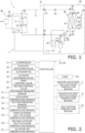
- Fig. 1 is a schematic configuration diagram of a refrigerant circuit
- Fig. 2 which is a schematic control block configuration diagram.
- the air-conditioning apparatus 1 is a refrigeration cycle apparatus that conditions air in a target space by performing a vapor compression refrigeration cycle.
- the air-conditioning apparatus 1 of the present embodiment can be used, for example, in cold districts, or the like, where a heating load is larger than a cooling load throughout a year.
- the air-conditioning apparatus 1 mainly includes an outdoor unit 20, an indoor unit 30, a liquid-side refrigerant connection pipe 6 and a gas-side refrigerant connection pipe 5 that connect the outdoor unit 20 and the indoor unit 30 to each other, a heat load circuit 50, a remote controller (not illustrated) that serves as an input device and an output device, and a controller 7 that controls operations of the air-conditioning apparatus 1.
- the air-conditioning apparatus 1 performs a refrigeration cycle in which a refrigerant enclosed in a refrigerant circuit 10 is compressed, cooled or condensed, decompressed, heated or evaporated, and then compressed again.
- the refrigerant circuit 10 is filled with a refrigerant for performing a vapor compression refrigeration cycle.
- the refrigerant is a flammable refrigerant. Examples of the flammable refrigerant include highly flammable refrigerants of classes A3 and B3, flammable refrigerants of classes A2 and B2, low-flammable refrigerants of classes A2L and B2L, and the like, in ASHRAE Safety Group.
- the refrigerant may be one or two or more kinds selected from the group consisting of R290, R600, and R600a.
- the refrigerant circuit 10 is filled with a refrigerant with a higher specific gravity than air.
- the refrigerant circuit 10 is filled with refrigerating machine oil together with the mixed refrigerant.
- the outdoor unit 20 is connected to the indoor unit 30 via the liquid-side refrigerant connection pipe 6 and the gas-side refrigerant connection pipe 5, and forms a portion of the refrigerant circuit 10.
- the outdoor unit 20 mainly includes a compressor 21, a four-way switching valve 22, an outdoor heat exchanger 40, a first control valve 43, a second control valve 44, an outdoor expansion valve 24, an outdoor fan 25, an accumulator 49, a liquid-side shutoff valve 29, and a gas-side shutoff valve 28.
- the outdoor unit 20 is disposed outdoors.
- the compressor 21 is a device that compresses a low-pressure refrigerant in the refrigeration cycle until the pressure of the refrigerant becomes high.
- a hermetic-structure compressor is used as the compressor 21.
- the hermetic-structure compressor has a displacement type compression element, such as a rotary type or scroll type compression element (not illustrated) that is rotationally driven by a compressor motor.
- the compressor motor is provided for changing the capacity, and the operation frequency thereof is controllable by an inverter.
- the four-way switching valve 22 switches between a cooling operation connection state and a heating operation connection state by switching the connection state.
- the four-way switching valve 22 connects a suction side of the compressor 21 to the gas-side shutoff valve 28 while connecting a discharge side of the compressor 21 to the outdoor heat exchanger 40. More specifically, in the cooling operation connection state, the discharge side of the compressor 21 is connected to a branch point A, which will be described later.
- the four-way switching valve 22 connects the suction side of the compressor 21 to the outdoor heat exchanger 40 while connecting the discharge side of the compressor 21 to the gas-side shutoff valve 28. More specifically, in the heating operation connection state, the suction side of the compressor 21 is connected to the branch point A, which will be described later.
- the accumulator 49 is provided between the four-way switching valve 22 and the suction side of the compressor 21. Accordingly, the compressor 21 is inhibited from sucking the refrigerant in a liquid state.
- the outdoor heat exchanger 40 is a heat-source-side heat exchanger in which a portion thereof functions as a condenser for a high-pressure refrigerant in the refrigeration cycle during a cooling operation, and the entirety thereof functions as an evaporator for a low-pressure refrigerant in the refrigeration cycle during a heating operation.
- the outdoor heat exchanger 40 includes a first outdoor heat exchanger 41 and a second outdoor heat exchanger 42 that are connected in parallel with each other in the refrigerant circuit 10.
- the first outdoor heat exchanger 41 and the second outdoor heat exchanger 42 of the outdoor heat exchanger 40 are each an air heat exchanger that causes the refrigerant flowing therein to exchange heat with the air passing outside.
- the first outdoor heat exchanger 41 and the second outdoor heat exchanger 42 of the outdoor heat exchanger 40 each include a plurality of heat transfer tubes connected to a header, and a plurality of fins fixed to the plurality of heat transfer tubes.
- An internal volume of the outdoor heat exchanger 40 is larger than an internal volume of an indoor heat exchanger 31.
- the internal volume of the outdoor heat exchanger 40 may be 1.5 times or more the internal volume of the indoor heat exchanger 31, and is preferably 2.0 times or more the internal volume of the indoor heat exchanger 31.
- the internal volume of the outdoor heat exchanger 40 may be 3 L or more and 10 L or less, or may be 4 L or more and 7 L or less.
- the internal volume of the outdoor heat exchanger 40 is the sum of internal volumes of the first outdoor heat exchanger 41 and the second outdoor heat exchanger 42.
- the internal volumes of the first outdoor heat exchanger 41 and the second outdoor heat exchanger 42 each refer to the volume of fluid in a case where the inside of the header and the heat transfer tubes are filled with the fluid.
- the first outdoor heat exchanger 41 functions as a condenser for a high-pressure refrigerant in the refrigeration cycle
- both the first outdoor heat exchanger 41 and the second outdoor heat exchanger 42 function as an evaporator for a low-pressure refrigerant in the refrigeration cycle.
- the first outdoor heat exchanger 41 is provided between the four-way switching valve 22 and the outdoor expansion valve 24.
- the branch point A at which a refrigerant flow path branches is provided between the four-way switching valve 22 and an end portion of the first outdoor heat exchanger 41 on a gas refrigerant side.
- a branch point B at which a refrigerant flow path branches is provided between an end portion of the first outdoor heat exchanger 41 on a liquid refrigerant side and the outdoor expansion valve 24.
- An end portion of the second outdoor heat exchanger 42 on the gas refrigerant side is connected to the branch point A, and an end portion of the second outdoor heat exchanger 42 on the liquid refrigerant side is connected to the branch point B.
- the second outdoor heat exchanger 42 is connected in parallel with the first outdoor heat exchanger 41.
- the first control valve 43 that is controllable to be opened and closed is provided between the end portion of the second outdoor heat exchanger 42 on the gas refrigerant side and the branch point A.
- the second control valve 44 that is controllable to be opened and closed is provided between the end portion of the second outdoor heat exchanger 42 on the liquid refrigerant side and the branch point B.
- the outdoor fan 25 generates an air flow for sucking outdoor air into the outdoor unit 20 and for discharging the air to the outside after the sucked air exchanges heat with the refrigerant in the outdoor heat exchanger 40.
- the outdoor fan 25 is rotationally driven by an outdoor fan motor.
- the outdoor fan 25 includes a plurality of fans.
- the outdoor fan 25 that includes the plurality of fans supplies the air flow generated by the driving operation to the entirety of the outdoor heat exchanger 40. More specifically, the air flow generated by the outdoor fan 25 is supplied to the entirety of the first outdoor heat exchanger 41, and is also supplied to the entirety of the second outdoor heat exchanger 42.
- the first outdoor heat exchanger 41 is disposed on the windward side of the second outdoor heat exchanger 42 in the direction of the air flow generated by the outdoor fan 25.
- the outdoor expansion valve 24 is provided between a liquid side end portion of the outdoor heat exchanger 40 and the liquid-side shutoff valve 29.
- the outdoor expansion valve 24 may be, for example, a mechanical expansion valve used with a capillary tube or a thermosensitive cylinder, but is preferably an electric expansion valve, the opening degree of which is adjustable through control.
- the liquid-side shutoff valve 29 is a manually operated valve disposed in the outdoor unit 20 at a portion connecting with the liquid-side refrigerant connection pipe 6.
- the gas-side shutoff valve 28 is a manually operated valve disposed in the outdoor unit 20 at a portion connecting with the gas-side refrigerant connection pipe 5.
- the outdoor unit 20 includes an outdoor unit control unit 27 that controls the operation of each component included in the outdoor unit 20.
- the outdoor unit control unit 27 has a microcomputer that includes a processor such as a central processing unit (CPU), memory such as ROM or RAM, and the like.
- the outdoor unit control unit 27 is connected to an indoor unit control unit 34 of each indoor unit 30 via a communication line, and transmits and receives control signals and the like.
- the outdoor unit 20 is provided with a discharge pressure sensor 61, a discharge temperature sensor 62, a suction pressure sensor 63, a suction temperature sensor 64, a first outdoor heat-exchange temperature sensor 65, a second outdoor heat-exchange temperature sensor 66, an outdoor air temperature sensor 67, and the like.
- Each of these sensors is electrically connected to the outdoor unit control unit 27, and transmits a detection signal to the outdoor unit control unit 27.
- the discharge pressure sensor 61 detects the pressure of the refrigerant flowing through a discharge pipe that connects the discharge side of the compressor 21 to one of the connection ports of the four-way switching valve 22.
- the discharge temperature sensor 62 detects the temperature of the refrigerant flowing through the discharge pipe.
- the suction pressure sensor 63 detects the pressure of the refrigerant flowing through a suction pipe that connects the suction side of the compressor 21 to one of the connection ports of the four-way switching valve 22.
- the suction temperature sensor 64 detects the temperature of the refrigerant flowing through the suction pipe.
- the first outdoor heat-exchange temperature sensor 65 detects the temperature of the refrigerant flowing between the liquid refrigerant side end portion of the first outdoor heat exchanger 41 and the branch point B.
- the second outdoor heat-exchange temperature sensor 66 detects the temperature of the refrigerant flowing between the liquid refrigerant side end portion of the second outdoor heat exchanger 42 and the branch point B.
- the outdoor air temperature sensor 67 detects the temperature of outdoor air before the outdoor air passes through the outdoor heat exchanger 40.
- the heat load circuit 50 is a circuit within which a heat medium, which is a fluid, circulates.
- the heat medium is not limited, and examples thereof include fluids such as water and brine.
- the heat load circuit 50 includes a heat load section 51 and a pump 52.
- the heat load section 51 is a section that processes a cooling load during a cooling operation and that processes a heating load during a heating operation.
- Examples of the heat load section 51 include floor heating panels used during a heating operation, coil parts of fan coil units for supplying cool air using blower fans during a cooling operation, and the like.
- the pump 52 circulates the heat medium in the heat load circuit 50, and the flow rate thereof is controllable.
- the heat load circuit 50 supplies a heat medium cooled by exchanging heat with the refrigerant in the indoor heat exchanger 31 to the heat load section 51.
- the heat medium warmed by processing the cooling load in the heat load section 51 is supplied to the indoor heat exchanger 31 again.
- the heat load circuit 50 supplies a heat medium warmed by exchanging heat with the refrigerant in the indoor heat exchanger 31 to the heat load section 51.
- the heat medium cooled by processing the heating load in the heat load section 51 is supplied to the indoor heat exchanger 31 again.
- the indoor unit 30 is provided near an air-conditioning target space.
- the indoor unit 30 is connected to the outdoor unit 20 via the liquid-side refrigerant connection pipe 6 and the gas-side refrigerant connection pipe 5, and forms a portion of the refrigerant circuit 10.
- the indoor unit 30 is disposed indoors.
- the indoor unit 30 includes the indoor heat exchanger 31.
- a liquid side of the indoor heat exchanger 31 is connected to the liquid-side refrigerant connection pipe 6, and a gas side end of the indoor heat exchanger 31 is connected to the gas-side refrigerant connection pipe 5.
- the indoor heat exchanger 31 is a heat exchanger that functions as an evaporator for a low-pressure refrigerant in the refrigeration cycle during a cooling operation, and as a condenser for a high-pressure refrigerant in the refrigeration cycle during a heating operation.
- the indoor heat exchanger 31 is a heat exchanger that causes the refrigerant flowing therein to exchange heat with the heat medium flowing through the heat load circuit 50.
- the indoor heat exchanger 31 of the present embodiment is a plate heat exchanger in which a plurality of plate-shaped members are stacked with regions through which the refrigerant flows and regions through which the heat medium flows being alternately arranged.
- the internal volume of the indoor heat exchanger 31 is smaller than the internal volume of the outdoor heat exchanger 40.
- the internal volume of the indoor heat exchanger 31 may be 2/3 or less the internal volume of the outdoor heat exchanger 40, and is preferably half or less than the internal volume of the outdoor heat exchanger 40.
- the internal volume of the indoor heat exchanger 31 may be 1 L or more and 4 L or less, or may be 1.5 L or more and 2.5 L or less.
- the internal volume of the indoor heat exchanger 31 refers to the volume of a space through which the refrigerant flows within the indoor heat exchanger 31, excluding a space through which the heat medium flows.
- the internal volume of the indoor heat exchanger 31 refers to the volume of the fluid in a case where the space through which the refrigerant flows within the indoor heat exchanger 31 is filled with the fluid.
- the indoor unit 30 includes the indoor unit control unit 34 that controls the operation of each component included in the indoor unit 30 and each component included in the heat load circuit 50.
- the indoor unit control unit 34 has a microcomputer that includes a processor such as a central processing unit (CPU), memory such as ROM or RAM, and the like.
- the indoor unit control unit 34 is connected to the outdoor unit control unit 27 via the communication line, and transmits and receives control signals and the like.
- the indoor unit 30 is provided with an indoor liquid-side heat-exchange temperature sensor 71, an indoor gas-side heat-exchange temperature sensor 73, a heat medium temperature sensor 53, and the like. Each of these sensors is electrically connected to the indoor unit control unit 34, and transmits a detection signal to the indoor unit control unit 34.
- the indoor liquid-side heat-exchange temperature sensor 71 detects the temperature of the refrigerant flowing through an outlet of the indoor heat exchanger 31 on the liquid refrigerant side, which is a side opposite to a side connected to the four-way switching valve 22.
- the indoor gas-side heat-exchange temperature sensor 73 detects the temperature of the refrigerant flowing through an outlet of the indoor heat exchanger 31 on the gas refrigerant side, which is the side connected to the four-way switching valve 22.
- the heat medium temperature sensor 53 detects the temperature of the heat medium flowing through an outlet of the indoor heat exchanger 31.
- the controller 7 that controls the operations of the air-conditioning apparatus 1 is configured by connecting the outdoor unit control unit 27 and the indoor unit control unit 34 to each other via the communication line.
- the controller 7 mainly includes a processor such as a central processing unit (CPU), memory such as ROM or RAM, and the like. Note that various processes and controls performed by the controller 7 are realized by the respective components included in the outdoor unit control unit 27 and/or the indoor unit control unit 34 functioning integrally.
- a processor such as a central processing unit (CPU)
- memory such as ROM or RAM, and the like. Note that various processes and controls performed by the controller 7 are realized by the respective components included in the outdoor unit control unit 27 and/or the indoor unit control unit 34 functioning integrally.
- a cooling operating mode, a heating operating mode, and a defrosting operating mode are provided as the operating modes.
- the defrost end condition is not limited, and examples thereof include the elapse of a predetermined time from the start of the defrosting operating mode, the temperature of the outdoor heat exchanger 40 becoming equal to or less than a predetermined value, and the like.
- the air-conditioning apparatus 1 sets the connection state of the four-way switching valve 22 to the cooling operation connection state, where the suction side of the compressor 21 is connected to the gas-side shutoff valve 28 while the discharge side of the compressor 21 is connected to the first outdoor heat exchanger 41 of the outdoor heat exchanger 40.
- the refrigerant filling the refrigerant circuit 10 is mainly circulated in the order of the compressor 21, the first outdoor heat exchanger 41, the outdoor expansion valve 24, and the indoor heat exchanger 31. Note that, during the cooling operation, the first control valve 43 and the second control valve 44 are closed, and the refrigerant does not flow through the second outdoor heat exchanger 42.
- the air-conditioning apparatus 1 used in environments with a relatively small cooling load, it is possible to process the cooling load without using the entire region of the outdoor heat exchanger 40 as a condenser.
- either the first control valve 43 or the second control valve 44 alone may be closed, for example.
- the outdoor fan 25 is controlled to be in a driving state.
- the flow rate of the pump 52 of the heat load circuit 50 is controlled on the basis of, for example, the temperature of the heat medium detected by the heat medium temperature sensor 53 and a set temperature in the heat load section 51.
- the refrigerant in the refrigerant circuit 10 is sucked into the compressor 21, compressed, and then discharged.
- the operation frequency of the compressor 21 is controlled through capacity control based on the cooling load required for the indoor unit 30.
- the gas refrigerant discharged from the compressor 21 passes through the four-way switching valve 22, and flows into the first outdoor heat exchanger 41 from the gas side end.
- the gas refrigerant flowing into the first outdoor heat exchanger 41 from the gas side end exchanges heat with outdoor-side air supplied by the outdoor fan 25 and is condensed in the first outdoor heat exchanger 41, becomes a liquid refrigerant, and flows out from the liquid side end of the first outdoor heat exchanger 41.
- the refrigerant flowing out from the liquid side end of the first outdoor heat exchanger 41 is decompressed when passing through the outdoor expansion valve 24.
- the outdoor expansion valve 24 is controlled, for example, so that the degree of superheating of the refrigerant to be sucked into the compressor 21 reaches a predetermined target value of the degree of superheating.
- the degree of superheating of the refrigerant to be sucked into the compressor 21 can be obtained, for example, by subtracting a saturation temperature corresponding to a suction pressure (pressure detected by the suction pressure sensor 63) from a suction temperature (temperature detected by the suction temperature sensor 64).
- the refrigerant decompressed at the outdoor expansion valve 24 passes through the liquid-side shutoff valve 29 and the liquid-side refrigerant connection pipe 6, and flows into the indoor unit 30.
- the refrigerant flowing into the indoor unit 30 flows into the indoor heat exchanger 31, where the refrigerant exchanges heat with the heat medium circulating through the heat load circuit 50 and is evaporated, becomes a gas refrigerant, and flows out from the gas side end of the indoor heat exchanger 31.
- the gas refrigerant flowing out from the gas side end of the indoor heat exchanger 31 flows into the gas-side refrigerant connection pipe 5.
- the refrigerant flowing through the gas-side refrigerant connection pipe 5 passes through the gas-side shutoff valve 28, the four-way switching valve 22, and the accumulator 49, and is again sucked into the compressor 21.
- the air-conditioning apparatus 1 sets the connection state of the four-way switching valve 22 to the heating operation connection state, where the suction side of the compressor 21 is connected to the outdoor heat exchanger 40 while the discharge side of the compressor 21 is connected to the gas-side shutoff valve 28.
- the refrigerant with which the refrigerant circuit 10 is filled is mainly circulated in the order of the compressor 21, the indoor heat exchanger 31, the outdoor expansion valve 24, and the outdoor heat exchanger 40.
- both the first control valve 43 and the second control valve 44 are controlled to be in an open state.
- the air-conditioning apparatus 1 is used in environments with a relatively large heating load, it is possible to process the large heating load by using the entire region of the outdoor heat exchanger 40 as an evaporator.
- the outdoor fan 25 is controlled to be in a driving state.
- the flow rate of the pump 52 of the heat load circuit 50 is controlled on the basis of, for example, the temperature of the heat medium detected by the heat medium temperature sensor 53 and the set temperature in the heat load section 51.
- the refrigerant in the refrigerant circuit 10 is sucked into the compressor 21, compressed, and then discharged.
- the operation frequency of the compressor 21 is controlled through capacity control based on the heating load required for the indoor unit 30.
- the gas refrigerant discharged from the compressor 21 flows through the four-way switching valve 22 and the gas-side refrigerant connection pipe 5, and then flows into the indoor unit 30.
- the refrigerant flowing into the indoor unit 30 flows into the indoor heat exchanger 31 from the gas side end, where the refrigerant exchanges heat with the heat medium circulating through the heat load circuit 50 and is condensed, becomes a refrigerant in a gas-liquid two-phase state or a liquid refrigerant, and flows out from the liquid side end of the indoor heat exchanger 31.
- the refrigerant flowing out from the liquid side end of the indoor heat exchanger 31 flows into the liquid-side refrigerant connection pipe 6.
- the refrigerant flowing through the liquid-side refrigerant connection pipe 6 flows into the outdoor unit 20, passes through the liquid-side shutoff valve 29, and is decompressed at the outdoor expansion valve 24 until the pressure of the refrigerant becomes low in the refrigeration cycle.
- the outdoor expansion valve 24 is controlled, for example, so that the degree of superheating of the refrigerant to be sucked into the compressor 21 reaches a predetermined target value of the degree of superheating.
- the refrigerant decompressed at the outdoor expansion valve 24 splits and flows into the respective liquid side ends of the first outdoor heat exchanger 41 and the second outdoor heat exchanger 42.
- the refrigerant flowing from the liquid side end into the first outdoor heat exchanger 41 exchanges heat with outdoor air supplied by the outdoor fan 25 and is evaporated in the first outdoor heat exchanger 41, becomes a gas refrigerant, and flows out from the gas side end of the first outdoor heat exchanger 41.
- the refrigerant flowing from the liquid side end into the second outdoor heat exchanger 42 exchanges heat with outdoor air supplied by the outdoor fan 25 and is evaporated in the second outdoor heat exchanger 42, becomes a gas refrigerant, and flows out from the gas side end of the second outdoor heat exchanger 42.
- the air-conditioning apparatus 1 sets the connection state of the four-way switching valve 22 to the cooling operation connection state, where the suction side of the compressor 21 is connected to the gas-side shutoff valve 28 while the discharge side of the compressor 21 is connected to both the first outdoor heat exchanger 41 and the second outdoor heat exchanger 42.
- the refrigerant filling the refrigerant circuit 10 is mainly circulated in the order of the compressor 21, the first outdoor heat exchanger 41 and the second outdoor heat exchanger 42, the outdoor expansion valve 24, and the indoor heat exchanger 31.
- the first control valve 43 and the second control valve 44 are opened in order to remove frost adhering to the first outdoor heat exchanger 41 and the second outdoor heat exchanger 42, so that the refrigerant is supplied to both the first outdoor heat exchanger 41 and the second outdoor heat exchanger 42.
- the outdoor fan 25 is stopped.
- the pump 52 of the heat load circuit 50 is stopped.
- the refrigerant in the refrigerant circuit 10 is sucked into the compressor 21, compressed, and then discharged.
- the compressor 21 is controlled, for example, to operate at a predetermined maximum frequency in order to promptly melt the frost.
- the gas refrigerant discharged from the compressor 21 passes through the four-way switching valve 22, and flows into each of the first outdoor heat exchanger 41 and the second outdoor heat exchanger 42.
- the gas refrigerant flowing into the first outdoor heat exchanger 41 from the gas side end is condensed by melting the frost adhering to the first outdoor heat exchanger 41, becomes a liquid refrigerant or a refrigerant in a gas-liquid two-phase state, and flows out from the liquid side end of the first outdoor heat exchanger 41.
- the gas refrigerant flowing into the second outdoor heat exchanger 42 from the gas side end is condensed by melting the frost adhering to the second outdoor heat exchanger 42, becomes a liquid refrigerant or a refrigerant in a gas-liquid two-phase state, and flows out from the liquid side end of the second outdoor heat exchanger 42.
- the refrigerant decompressed at the outdoor expansion valve 24 passes through the liquid-side shutoff valve 29 and the liquid-side refrigerant connection pipe 6, and flows into the indoor unit 30.
- the refrigerant flowing into the indoor unit 30 flows into the indoor heat exchanger 31, where the refrigerant exchanges heat with the heat medium circulating through the heat load circuit 50 and is evaporated, becomes a gas refrigerant, and flows out from the gas side end of the indoor heat exchanger 31.
- the gas refrigerant flowing out from the gas side end of the indoor heat exchanger 31 flows into the gas-side refrigerant connection pipe 5.
- the refrigerant flowing through the gas-side refrigerant connection pipe 5 passes through the gas-side shutoff valve 28, the four-way switching valve 22, and the accumulator 49, and is again sucked into the compressor 21.
- the air-conditioning apparatus 1 of the present embodiment causes the entirety of the outdoor heat exchanger 40 that has a larger internal volume than the indoor heat exchanger 31 to function as an evaporator for a refrigerant during the heating operation, and thereby can easily ensure the capacity during the heating operation. Therefore, even in a case where the air-conditioning apparatus 1 is used in environments with a large heating load, such as cold districts, the air-conditioning apparatus 1 can easily process the heating load.
- the air-conditioning apparatus 1 causes only the first outdoor heat exchanger 41 of the outdoor heat exchanger 40 to function as a condenser for the refrigerant, and does not cause the second outdoor heat exchanger 42 to function as a condenser for the refrigerant.
- the amount of liquid refrigerant present within the outdoor heat exchanger 40 can be reduced to a small amount, thereby enabling a reduction in the amount of refrigerant filling the air-conditioning apparatus 1.
- the air-conditioning apparatus 1 can easily process the cooling load even in a case where only the first outdoor heat exchanger 41 of the outdoor heat exchanger 40 is used.
- the amount of refrigerant filling the air-conditioning apparatus 1 can be reduced to a small amount.
- the amount of leakage can be reduced to a small amount even if a refrigerant leakage occurs. This can suppress an increase in concentration of leaking refrigerant during the refrigerant leakage, thereby enabling a reduction in the risk of ignition.
- the amount of excess refrigerant in the air-conditioning apparatus 1 can be reduced to a small amount, it is possible to eliminate the necessity of providing a receiver in the refrigerant circuit 10 for storing a liquid refrigerant at a location where a liquid refrigerant or a refrigerant in a gas-liquid two-phase state flows, or even if such a receiver is provided, the internal volume thereof can be reduced to be small.
- the outdoor heat exchanger 40 is an air heat exchanger that has a larger internal volume than the indoor heat exchanger 31, the air-conditioning apparatus 1 can easily ensure a heat source even during the heating operation in cold districts.
- the air flow generated by the outdoor fan 25 is supplied to the entirety of the first outdoor heat exchanger 41, and is also supplied to the entirety of the second outdoor heat exchanger 42. Therefore, either a case where the refrigerant is made to flow through both the first outdoor heat exchanger 41 and the second outdoor heat exchanger 42 or a case where the refrigerant is made to flow through only the first outdoor heat exchanger 41, heat exchange can be performed in the entirety of the first outdoor heat exchanger 41 and in the entirety of the second outdoor heat exchanger 42 or in the entirety of the first outdoor heat exchanger 41, by using the air flow generated by the outdoor fan 25 in both cases.
- a plurality of refrigerant flow paths are formed in the air-conditioning apparatus 1 as refrigerant flow paths passing through the outdoor heat exchanger 40.
- the paths include a refrigerant flow path passing through the first outdoor heat exchanger 41 and a refrigerant flow path passing through the second outdoor heat exchanger 42. Accordingly, compared to a case where the outdoor heat exchanger 40 is configured to be a single refrigerant flow path, it becomes possible to reduce the pressure loss when the refrigerant passes therethrough.
- the outdoor heat exchanger 40 includes the first outdoor heat exchanger 41 and the second outdoor heat exchanger 42, and the first outdoor heat exchanger 41 is disposed on the windward side of the second outdoor heat exchanger 42 in the direction of the air flow generated by the outdoor fan 25.
- the outdoor heat exchanger may include a plurality of separate heat exchangers, which are more than two.
- the outdoor heat exchanger may include more than two refrigerant flow paths, for example.
- the arrangement of the plurality of heat exchangers included in the outdoor heat exchanger is not limited to an arrangement in which the heat exchangers are arranged in the direction of the air flow generated by the outdoor fan 25.
- the outdoor heat exchanger may be a heat exchanger in which a plurality of vertically arranged heat transfer tube groups are provided in three rows side by side in the direction of the air flow, as in an outdoor heat exchanger 140 illustrated in Fig. 3 .
- the outdoor heat exchanger may include first outdoor heat exchangers 141, second outdoor heat exchangers 142, and third outdoor heat exchangers 143, as in the outdoor heat exchanger 140.
- the heat transfer tubes disposed in adjacent rows in the direction of the air flow be staggered in position in order not to overlap each other when viewed from the direction of the air flow.
- a refrigerant splits into three separate flow paths and flows therethrough as illustrated in Fig. 4 .
- the refrigerant flows into the first outdoor heat exchanger 141 from a position in a middle stage on the leeward side in the outdoor heat exchanger 140, flows through the heat transfer tubes, then moves to an upper stage in the outdoor heat exchanger 140 when making a turn at an end portion, flows through the heat transfer tubes in the upper stage, makes another turn, and flows through the heat transfer tubes in an upper stage on the windward side in the outdoor heat exchanger 140.
- the refrigerant flows into the second outdoor heat exchanger 142 from a position in a lower stage on the leeward side in the outdoor heat exchanger 140, flows through the heat transfer tubes, then makes a turn at an end portion, flows through the heat transfer tubes in a lower stage in the outdoor heat exchanger 140, moves to a middle stage on the windward side in the outdoor heat exchanger 140 when making another turn, and flows through the heat transfer tubes.
- the refrigerant flows into the third outdoor heat exchanger 143 from a position in an upper stage on the leeward side in the outdoor heat exchanger 140, flows through the heat transfer tubes, then moves to a middle stage in the outdoor heat exchanger 140 when making a turn at an end portion, flows through the heat transfer tubes, moves to a lower stage on the windward side in the outdoor heat exchanger 140 when making another turn, and flows through the heat transfer tubes.
- the refrigerant is not made to flow through the first outdoor heat exchanger 141 and the second outdoor heat exchanger 142, but is made to flow only through the third outdoor heat exchanger 143.
- the third outdoor heat exchanger 143 can be provided between the branch point A and the branch point B, and the first outdoor heat exchanger 141 and the second outdoor heat exchanger 142 can be connected in parallel with each other between the first control valve 43 and the second control valve 44.
- the indoor heat exchanger 31 may be an air heat exchanger, for example.
- the indoor heat exchanger 31 may perform heat exchange using air supplied from an indoor fan in order to adjust the temperature of air in the space where the indoor heat exchanger 31 is disposed.
- the air-conditioning apparatus 1 may include, for example, a plurality of indoor units 30 that are connected in parallel with each other with respect to the outdoor unit 20.
Landscapes
- Engineering & Computer Science (AREA)
- Physics & Mathematics (AREA)
- Mechanical Engineering (AREA)
- Thermal Sciences (AREA)
- General Engineering & Computer Science (AREA)
- Compression-Type Refrigeration Machines With Reversible Cycles (AREA)
Abstract
Description
- The present disclosure relates to an air-conditioning apparatus.
- In recent years, from the viewpoint of global environmental protection, the introduction of air-conditioning apparatuses that perform a heating operation using air as a heat source has been promoted even in cold districts.
- As an example of such air-conditioning apparatuses used in cold districts, an air-conditioning apparatus that adjusts heating capacity in accordance with an indoor heating load has been proposed as described in PTL 1 (International Publication No.
2020/208776 ). - In some cases, in order to sufficiently ensure capacity during heating operation even in a case where the outdoor air temperature is low as in cold districts, an air-conditioning apparatus with a large-volume outdoor heat exchanger that functions as an evaporator is used. In a case of performing a cooling operation by using this air-conditioning apparatus, the outdoor heat exchanger functions as a condenser for a refrigerant. In this case however, since a large amount of liquid refrigerant is likely to be present within the large-volume outdoor heat exchanger, the amount of the refrigerant filling the refrigerant circuit tends to increase.
- An air-conditioning apparatus according to a first aspect includes: a first heat exchanger; a second heat exchanger; and a switching section. The switching section switches between a first operation and a second operation. The first operation causes the first heat exchanger to function as a condenser for a refrigerant and causes the second heat exchanger to function as an evaporator for the refrigerant. The second operation causes the first heat exchanger to function as an evaporator for the refrigerant and causes the second heat exchanger to function as a condenser for the refrigerant. An internal volume of the first heat exchanger is smaller than an internal volume of the second heat exchanger. An internal volume of a region through which the refrigerant flows in the second heat exchanger during the second operation is smaller than an internal volume of a region through which the refrigerant flows in the second heat exchanger during the first operation.
- This air-conditioning apparatus causes the second heat exchanger that has a larger internal volume than the first heat exchanger to function as an evaporator for the refrigerant during the first operation, thereby easily ensuring the capacity during the first operation. In addition, in the air-conditioning apparatus, the internal volume of the region through which the refrigerant flows in the second heat exchanger during the second operation that causes the second heat exchanger to function as a condenser for the refrigerant is smaller than the internal volume of the region through which the refrigerant flows in the second heat exchanger during the first operation. Therefore, the amount of the liquid refrigerant retained in the second heat exchanger during the second operation can be reduced to a small amount. This enables a reduction in the amount of refrigerant filling the air-conditioning apparatus.
- An air-conditioning apparatus according to a second aspect is the air-conditioning apparatus according to the first aspect, in which the second heat exchanger is an air heat exchanger that causes the refrigerant flowing inside the second heat exchanger to exchange heat with air flowing outside.
- Even in a case where the refrigerant flowing through the second heat exchanger that functions as an evaporator when the first operation is performed exchanges heat with low temperature outdoor air in cold districts, this air-conditioning apparatus can easily ensure the capacity because the second heat exchanger has a larger internal volume than the first heat exchanger.
- An air-conditioning apparatus according to a third aspect is the air-conditioning apparatus according to the second aspect, and further includes a blower section. The blower section is capable of supplying an air flow to an entirety of the second heat exchanger.
- This air-conditioning apparatus can easily ensure the amount of heat exchange because the air flow is supplied to the entirety of the second heat exchanger.
- An air-conditioning apparatus according to a fourth aspect is the air-conditioning apparatus according to the third aspect, in which during the second operation, a flow path through which the refrigerant flows in the second heat exchanger has no overlapping portion per se when viewed from a direction of the air flow generated by the blower section.
- Even in a case where the internal volume of the region through which the refrigerant passes in the second heat exchanger during the second operation is smaller than that during the first operation, this air-conditioning apparatus can perform efficient heat exchange.
- An air-conditioning apparatus according to a fifth aspect is the air-conditioning apparatus according to any one of the first to fourth aspects, in which during the first operation, the refrigerant flows through an entirety of the internal volume of the second heat exchanger.
- This air-conditioning apparatus can easily ensure the capacity in the second heat exchanger that functions as an evaporator when performing the first operation.
- An air-conditioning apparatus according to a sixth aspect is the air-conditioning apparatus according to any one of the first to fourth aspects, in which during the first operation, the second heat exchanger includes two or more flow paths through which the refrigerant flows.
- This air-conditioning apparatus can reduce the pressure loss in the second heat exchanger that functions as an evaporator when performing the first operation.
- An air-conditioning apparatus according to a seventh aspect is the air-conditioning apparatus according to any one of the first to sixth aspects, in which the second heat exchanger includes a plurality of heat transfer tubes. During the second operation, the heat transfer tubes included in the second heat exchanger include one or more heat transfer tubes through which the refrigerant does not flow.
- This air-conditioning apparatus can reduce the amount of the liquid refrigerant retained in the second heat exchanger to a small amount during the second operation that causes the second heat exchanger to function as a condenser for the refrigerant.
- An air-conditioning apparatus according to an eighth aspect is the air-conditioning apparatus according to any one of the first to seventh aspects, in which the internal volume of the first heat exchanger is 2/3 or less the internal volume of the second heat exchanger.
- Even in a case where the internal volume of the second heat exchanger is large, this air-conditioning apparatus can reduce the filling amount of refrigerant to a small amount.
- An air-conditioning apparatus according to a ninth aspect is the air-conditioning apparatus according to any one of the first to eighth aspects, in which the second heat exchanger is a heat-source-side heat exchanger. The first heat exchanger is a utilization-side heat exchanger.
- This air-conditioning apparatus can obtain a large amount of heat during the first operation in the second heat exchanger that has a larger internal volume than the first heat exchanger.
- An air-conditioning apparatus according to a tenth aspect is the air-conditioning apparatus according to any one of the first to ninth aspects, in which the refrigerant is a flammable refrigerant.
- Even in a case where the flammable refrigerant is used, this air-conditioning apparatus enables a reduction in the filling amount of the flammable refrigerant.
- An air-conditioning apparatus according to an eleventh aspect is the air-conditioning apparatus according to the tenth aspect, in which the flammable refrigerant includes one or two or more kinds selected from the group consisting of R290, R600, and R600a.
- Even in a case where an easily flammable refrigerant is used, this air-conditioning apparatus can reduce the risk of ignition.
-
- [
Fig. 1] Fig. 1 is a schematic configuration diagram of a refrigerant circuit. - [
Fig. 2] Fig. 2 is a schematic control block configuration diagram of an air-conditioning apparatus. - [
Fig. 3] Fig. 3 is a schematic external configuration diagram of an outdoor heat exchanger according to another embodiment A. - [
Fig. 4] Fig. 4 is a diagram illustrating flows of a refrigerant in the outdoor heat exchanger according to the another embodiment A during a heating operation. - Hereinafter, an air-conditioning apparatus 1 will be described with reference to
Fig. 1 , which is a schematic configuration diagram of a refrigerant circuit, andFig. 2 , which is a schematic control block configuration diagram. - The air-conditioning apparatus 1 is a refrigeration cycle apparatus that conditions air in a target space by performing a vapor compression refrigeration cycle. The air-conditioning apparatus 1 of the present embodiment can be used, for example, in cold districts, or the like, where a heating load is larger than a cooling load throughout a year.
- The air-conditioning apparatus 1 mainly includes an
outdoor unit 20, anindoor unit 30, a liquid-siderefrigerant connection pipe 6 and a gas-side refrigerant connection pipe 5 that connect theoutdoor unit 20 and theindoor unit 30 to each other, aheat load circuit 50, a remote controller (not illustrated) that serves as an input device and an output device, and acontroller 7 that controls operations of the air-conditioning apparatus 1. - The air-conditioning apparatus 1 performs a refrigeration cycle in which a refrigerant enclosed in a
refrigerant circuit 10 is compressed, cooled or condensed, decompressed, heated or evaporated, and then compressed again. In the present embodiment, therefrigerant circuit 10 is filled with a refrigerant for performing a vapor compression refrigeration cycle. The refrigerant is a flammable refrigerant. Examples of the flammable refrigerant include highly flammable refrigerants of classes A3 and B3, flammable refrigerants of classes A2 and B2, low-flammable refrigerants of classes A2L and B2L, and the like, in ASHRAE Safety Group. More specifically, the refrigerant may be one or two or more kinds selected from the group consisting of R290, R600, and R600a. Note that in the present embodiment, therefrigerant circuit 10 is filled with a refrigerant with a higher specific gravity than air. In addition, therefrigerant circuit 10 is filled with refrigerating machine oil together with the mixed refrigerant. - The
outdoor unit 20 is connected to theindoor unit 30 via the liquid-siderefrigerant connection pipe 6 and the gas-side refrigerant connection pipe 5, and forms a portion of therefrigerant circuit 10. Theoutdoor unit 20 mainly includes acompressor 21, a four-way switching valve 22, anoutdoor heat exchanger 40, afirst control valve 43, asecond control valve 44, anoutdoor expansion valve 24, anoutdoor fan 25, anaccumulator 49, a liquid-side shutoff valve 29, and a gas-side shutoff valve 28. In the present embodiment, theoutdoor unit 20 is disposed outdoors. - The
compressor 21 is a device that compresses a low-pressure refrigerant in the refrigeration cycle until the pressure of the refrigerant becomes high. Here, a hermetic-structure compressor is used as thecompressor 21. The hermetic-structure compressor has a displacement type compression element, such as a rotary type or scroll type compression element (not illustrated) that is rotationally driven by a compressor motor. The compressor motor is provided for changing the capacity, and the operation frequency thereof is controllable by an inverter. - The four-
way switching valve 22 switches between a cooling operation connection state and a heating operation connection state by switching the connection state. In the cooling operation connection state, the four-way switching valve 22 connects a suction side of thecompressor 21 to the gas-side shutoff valve 28 while connecting a discharge side of thecompressor 21 to theoutdoor heat exchanger 40. More specifically, in the cooling operation connection state, the discharge side of thecompressor 21 is connected to a branch point A, which will be described later. On the other hand, in the heating operation connection state, the four-way switching valve 22 connects the suction side of thecompressor 21 to theoutdoor heat exchanger 40 while connecting the discharge side of thecompressor 21 to the gas-side shutoff valve 28. More specifically, in the heating operation connection state, the suction side of thecompressor 21 is connected to the branch point A, which will be described later. - The
accumulator 49 is provided between the four-way switching valve 22 and the suction side of thecompressor 21. Accordingly, thecompressor 21 is inhibited from sucking the refrigerant in a liquid state. - The
outdoor heat exchanger 40 is a heat-source-side heat exchanger in which a portion thereof functions as a condenser for a high-pressure refrigerant in the refrigeration cycle during a cooling operation, and the entirety thereof functions as an evaporator for a low-pressure refrigerant in the refrigeration cycle during a heating operation. Theoutdoor heat exchanger 40 includes a firstoutdoor heat exchanger 41 and a secondoutdoor heat exchanger 42 that are connected in parallel with each other in therefrigerant circuit 10. The firstoutdoor heat exchanger 41 and the secondoutdoor heat exchanger 42 of theoutdoor heat exchanger 40 are each an air heat exchanger that causes the refrigerant flowing therein to exchange heat with the air passing outside. The firstoutdoor heat exchanger 41 and the secondoutdoor heat exchanger 42 of theoutdoor heat exchanger 40 each include a plurality of heat transfer tubes connected to a header, and a plurality of fins fixed to the plurality of heat transfer tubes. An internal volume of theoutdoor heat exchanger 40 is larger than an internal volume of anindoor heat exchanger 31. The internal volume of theoutdoor heat exchanger 40 may be 1.5 times or more the internal volume of theindoor heat exchanger 31, and is preferably 2.0 times or more the internal volume of theindoor heat exchanger 31. For example, the internal volume of theoutdoor heat exchanger 40 may be 3 L or more and 10 L or less, or may be 4 L or more and 7 L or less. Note that the internal volume of theoutdoor heat exchanger 40 is the sum of internal volumes of the firstoutdoor heat exchanger 41 and the secondoutdoor heat exchanger 42. The internal volumes of the firstoutdoor heat exchanger 41 and the secondoutdoor heat exchanger 42 each refer to the volume of fluid in a case where the inside of the header and the heat transfer tubes are filled with the fluid. - In the present embodiment, during a cooling operation, the first
outdoor heat exchanger 41 functions as a condenser for a high-pressure refrigerant in the refrigeration cycle, and during a heating operation, both the firstoutdoor heat exchanger 41 and the secondoutdoor heat exchanger 42 function as an evaporator for a low-pressure refrigerant in the refrigeration cycle. The firstoutdoor heat exchanger 41 is provided between the four-way switching valve 22 and theoutdoor expansion valve 24. The branch point A at which a refrigerant flow path branches is provided between the four-way switching valve 22 and an end portion of the firstoutdoor heat exchanger 41 on a gas refrigerant side. A branch point B at which a refrigerant flow path branches is provided between an end portion of the firstoutdoor heat exchanger 41 on a liquid refrigerant side and theoutdoor expansion valve 24. An end portion of the secondoutdoor heat exchanger 42 on the gas refrigerant side is connected to the branch point A, and an end portion of the secondoutdoor heat exchanger 42 on the liquid refrigerant side is connected to the branch point B. Thus, the secondoutdoor heat exchanger 42 is connected in parallel with the firstoutdoor heat exchanger 41. Thefirst control valve 43 that is controllable to be opened and closed is provided between the end portion of the secondoutdoor heat exchanger 42 on the gas refrigerant side and the branch point A. Thesecond control valve 44 that is controllable to be opened and closed is provided between the end portion of the secondoutdoor heat exchanger 42 on the liquid refrigerant side and the branch point B. - The
outdoor fan 25 generates an air flow for sucking outdoor air into theoutdoor unit 20 and for discharging the air to the outside after the sucked air exchanges heat with the refrigerant in theoutdoor heat exchanger 40. Theoutdoor fan 25 is rotationally driven by an outdoor fan motor. In the present embodiment, theoutdoor fan 25 includes a plurality of fans. Theoutdoor fan 25 that includes the plurality of fans supplies the air flow generated by the driving operation to the entirety of theoutdoor heat exchanger 40. More specifically, the air flow generated by theoutdoor fan 25 is supplied to the entirety of the firstoutdoor heat exchanger 41, and is also supplied to the entirety of the secondoutdoor heat exchanger 42. Note that in the present embodiment, the firstoutdoor heat exchanger 41 is disposed on the windward side of the secondoutdoor heat exchanger 42 in the direction of the air flow generated by theoutdoor fan 25. - The
outdoor expansion valve 24 is provided between a liquid side end portion of theoutdoor heat exchanger 40 and the liquid-side shutoff valve 29. Theoutdoor expansion valve 24 may be, for example, a mechanical expansion valve used with a capillary tube or a thermosensitive cylinder, but is preferably an electric expansion valve, the opening degree of which is adjustable through control. - The liquid-
side shutoff valve 29 is a manually operated valve disposed in theoutdoor unit 20 at a portion connecting with the liquid-siderefrigerant connection pipe 6. - The gas-
side shutoff valve 28 is a manually operated valve disposed in theoutdoor unit 20 at a portion connecting with the gas-side refrigerant connection pipe 5. - The
outdoor unit 20 includes an outdoorunit control unit 27 that controls the operation of each component included in theoutdoor unit 20. The outdoorunit control unit 27 has a microcomputer that includes a processor such as a central processing unit (CPU), memory such as ROM or RAM, and the like. The outdoorunit control unit 27 is connected to an indoorunit control unit 34 of eachindoor unit 30 via a communication line, and transmits and receives control signals and the like. - The
outdoor unit 20 is provided with adischarge pressure sensor 61, adischarge temperature sensor 62, asuction pressure sensor 63, asuction temperature sensor 64, a first outdoor heat-exchange temperature sensor 65, a second outdoor heat-exchange temperature sensor 66, an outdoorair temperature sensor 67, and the like. Each of these sensors is electrically connected to the outdoorunit control unit 27, and transmits a detection signal to the outdoorunit control unit 27. Thedischarge pressure sensor 61 detects the pressure of the refrigerant flowing through a discharge pipe that connects the discharge side of thecompressor 21 to one of the connection ports of the four-way switching valve 22. Thedischarge temperature sensor 62 detects the temperature of the refrigerant flowing through the discharge pipe. Thesuction pressure sensor 63 detects the pressure of the refrigerant flowing through a suction pipe that connects the suction side of thecompressor 21 to one of the connection ports of the four-way switching valve 22. Thesuction temperature sensor 64 detects the temperature of the refrigerant flowing through the suction pipe. The first outdoor heat-exchange temperature sensor 65 detects the temperature of the refrigerant flowing between the liquid refrigerant side end portion of the firstoutdoor heat exchanger 41 and the branch point B. The second outdoor heat-exchange temperature sensor 66 detects the temperature of the refrigerant flowing between the liquid refrigerant side end portion of the secondoutdoor heat exchanger 42 and the branch point B. The outdoorair temperature sensor 67 detects the temperature of outdoor air before the outdoor air passes through theoutdoor heat exchanger 40. - The
heat load circuit 50 is a circuit within which a heat medium, which is a fluid, circulates. The heat medium is not limited, and examples thereof include fluids such as water and brine. - The
heat load circuit 50 includes aheat load section 51 and apump 52. - The
heat load section 51 is a section that processes a cooling load during a cooling operation and that processes a heating load during a heating operation. Examples of theheat load section 51 include floor heating panels used during a heating operation, coil parts of fan coil units for supplying cool air using blower fans during a cooling operation, and the like. - The
pump 52 circulates the heat medium in theheat load circuit 50, and the flow rate thereof is controllable. - During a cooling operation, the
heat load circuit 50 supplies a heat medium cooled by exchanging heat with the refrigerant in theindoor heat exchanger 31 to theheat load section 51. The heat medium warmed by processing the cooling load in theheat load section 51 is supplied to theindoor heat exchanger 31 again. - During a heating operation, the
heat load circuit 50 supplies a heat medium warmed by exchanging heat with the refrigerant in theindoor heat exchanger 31 to theheat load section 51. The heat medium cooled by processing the heating load in theheat load section 51 is supplied to theindoor heat exchanger 31 again. - The
indoor unit 30 is provided near an air-conditioning target space. Theindoor unit 30 is connected to theoutdoor unit 20 via the liquid-siderefrigerant connection pipe 6 and the gas-side refrigerant connection pipe 5, and forms a portion of therefrigerant circuit 10. In the present embodiment, theindoor unit 30 is disposed indoors. - The
indoor unit 30 includes theindoor heat exchanger 31. - A liquid side of the
indoor heat exchanger 31 is connected to the liquid-siderefrigerant connection pipe 6, and a gas side end of theindoor heat exchanger 31 is connected to the gas-side refrigerant connection pipe 5. Theindoor heat exchanger 31 is a heat exchanger that functions as an evaporator for a low-pressure refrigerant in the refrigeration cycle during a cooling operation, and as a condenser for a high-pressure refrigerant in the refrigeration cycle during a heating operation. - The
indoor heat exchanger 31 is a heat exchanger that causes the refrigerant flowing therein to exchange heat with the heat medium flowing through theheat load circuit 50. Theindoor heat exchanger 31 of the present embodiment is a plate heat exchanger in which a plurality of plate-shaped members are stacked with regions through which the refrigerant flows and regions through which the heat medium flows being alternately arranged. The internal volume of theindoor heat exchanger 31 is smaller than the internal volume of theoutdoor heat exchanger 40. The internal volume of theindoor heat exchanger 31 may be 2/3 or less the internal volume of theoutdoor heat exchanger 40, and is preferably half or less than the internal volume of theoutdoor heat exchanger 40. For example, the internal volume of theindoor heat exchanger 31 may be 1 L or more and 4 L or less, or may be 1.5 L or more and 2.5 L or less. Note that the internal volume of theindoor heat exchanger 31 refers to the volume of a space through which the refrigerant flows within theindoor heat exchanger 31, excluding a space through which the heat medium flows. Specifically, the internal volume of theindoor heat exchanger 31 refers to the volume of the fluid in a case where the space through which the refrigerant flows within theindoor heat exchanger 31 is filled with the fluid. - In addition, the
indoor unit 30 includes the indoorunit control unit 34 that controls the operation of each component included in theindoor unit 30 and each component included in theheat load circuit 50. The indoorunit control unit 34 has a microcomputer that includes a processor such as a central processing unit (CPU), memory such as ROM or RAM, and the like. The indoorunit control unit 34 is connected to the outdoorunit control unit 27 via the communication line, and transmits and receives control signals and the like. - The
indoor unit 30 is provided with an indoor liquid-side heat-exchange temperature sensor 71, an indoor gas-side heat-exchange temperature sensor 73, a heatmedium temperature sensor 53, and the like. Each of these sensors is electrically connected to the indoorunit control unit 34, and transmits a detection signal to the indoorunit control unit 34. The indoor liquid-side heat-exchange temperature sensor 71 detects the temperature of the refrigerant flowing through an outlet of theindoor heat exchanger 31 on the liquid refrigerant side, which is a side opposite to a side connected to the four-way switching valve 22. The indoor gas-side heat-exchange temperature sensor 73 detects the temperature of the refrigerant flowing through an outlet of theindoor heat exchanger 31 on the gas refrigerant side, which is the side connected to the four-way switching valve 22. The heatmedium temperature sensor 53 detects the temperature of the heat medium flowing through an outlet of theindoor heat exchanger 31. - In the air-conditioning apparatus 1, the
controller 7 that controls the operations of the air-conditioning apparatus 1 is configured by connecting the outdoorunit control unit 27 and the indoorunit control unit 34 to each other via the communication line. - The
controller 7 mainly includes a processor such as a central processing unit (CPU), memory such as ROM or RAM, and the like. Note that various processes and controls performed by thecontroller 7 are realized by the respective components included in the outdoorunit control unit 27 and/or the indoorunit control unit 34 functioning integrally. - Hereinafter, operating modes will be described.
- A cooling operating mode, a heating operating mode, and a defrosting operating mode are provided as the operating modes.
- The
controller 7 determines whether the operation mode is the cooling operating mode or the heating operating mode on the basis of an instruction received from the remote controller or the like, and executes the determined operation mode. In addition, thecontroller 7 executes the defrosting operating mode in a case where a predetermined defrost start condition is met during the execution of the heating operating mode. Furthermore, thecontroller 7 ends the defrosting operation in a case where a predetermined defrost end condition is met during the execution of the defrosting operating mode, and resumes the heating operating mode. The defrost start condition is not limited, and can be established on the basis of, for example, the continuous operation time of the heating operation or the temperature of outdoor air. In addition, the defrost end condition is not limited, and examples thereof include the elapse of a predetermined time from the start of the defrosting operating mode, the temperature of theoutdoor heat exchanger 40 becoming equal to or less than a predetermined value, and the like. - In the cooling operating mode, the air-conditioning apparatus 1 sets the connection state of the four-
way switching valve 22 to the cooling operation connection state, where the suction side of thecompressor 21 is connected to the gas-side shutoff valve 28 while the discharge side of thecompressor 21 is connected to the firstoutdoor heat exchanger 41 of theoutdoor heat exchanger 40. In this state, the refrigerant filling therefrigerant circuit 10 is mainly circulated in the order of thecompressor 21, the firstoutdoor heat exchanger 41, theoutdoor expansion valve 24, and theindoor heat exchanger 31. Note that, during the cooling operation, thefirst control valve 43 and thesecond control valve 44 are closed, and the refrigerant does not flow through the secondoutdoor heat exchanger 42. As for the air-conditioning apparatus 1 used in environments with a relatively small cooling load, it is possible to process the cooling load without using the entire region of theoutdoor heat exchanger 40 as a condenser. Note that, during the cooling operation, either thefirst control valve 43 or thesecond control valve 44 alone may be closed, for example. In addition, theoutdoor fan 25 is controlled to be in a driving state. The flow rate of thepump 52 of theheat load circuit 50 is controlled on the basis of, for example, the temperature of the heat medium detected by the heatmedium temperature sensor 53 and a set temperature in theheat load section 51. - When the cooling operating mode is started, the refrigerant in the
refrigerant circuit 10 is sucked into thecompressor 21, compressed, and then discharged. - The operation frequency of the
compressor 21 is controlled through capacity control based on the cooling load required for theindoor unit 30. - The gas refrigerant discharged from the
compressor 21 passes through the four-way switching valve 22, and flows into the firstoutdoor heat exchanger 41 from the gas side end. - The gas refrigerant flowing into the first
outdoor heat exchanger 41 from the gas side end exchanges heat with outdoor-side air supplied by theoutdoor fan 25 and is condensed in the firstoutdoor heat exchanger 41, becomes a liquid refrigerant, and flows out from the liquid side end of the firstoutdoor heat exchanger 41. - The refrigerant flowing out from the liquid side end of the first
outdoor heat exchanger 41 is decompressed when passing through theoutdoor expansion valve 24. Note that theoutdoor expansion valve 24 is controlled, for example, so that the degree of superheating of the refrigerant to be sucked into thecompressor 21 reaches a predetermined target value of the degree of superheating. Here, the degree of superheating of the refrigerant to be sucked into thecompressor 21 can be obtained, for example, by subtracting a saturation temperature corresponding to a suction pressure (pressure detected by the suction pressure sensor 63) from a suction temperature (temperature detected by the suction temperature sensor 64). - The refrigerant decompressed at the
outdoor expansion valve 24 passes through the liquid-side shutoff valve 29 and the liquid-siderefrigerant connection pipe 6, and flows into theindoor unit 30. - The refrigerant flowing into the
indoor unit 30 flows into theindoor heat exchanger 31, where the refrigerant exchanges heat with the heat medium circulating through theheat load circuit 50 and is evaporated, becomes a gas refrigerant, and flows out from the gas side end of theindoor heat exchanger 31. The gas refrigerant flowing out from the gas side end of theindoor heat exchanger 31 flows into the gas-side refrigerant connection pipe 5. - The refrigerant flowing through the gas-side refrigerant connection pipe 5 passes through the gas-
side shutoff valve 28, the four-way switching valve 22, and theaccumulator 49, and is again sucked into thecompressor 21. - In the heating operating mode, the air-conditioning apparatus 1 sets the connection state of the four-
way switching valve 22 to the heating operation connection state, where the suction side of thecompressor 21 is connected to theoutdoor heat exchanger 40 while the discharge side of thecompressor 21 is connected to the gas-side shutoff valve 28. In this state, the refrigerant with which therefrigerant circuit 10 is filled is mainly circulated in the order of thecompressor 21, theindoor heat exchanger 31, theoutdoor expansion valve 24, and theoutdoor heat exchanger 40. Here, in the heating operating mode, in order to cause the refrigerant to flow through the entirety of theoutdoor heat exchanger 40, more specifically, in order to cause the refrigerant to flow through both the firstoutdoor heat exchanger 41 and the secondoutdoor heat exchanger 42, both thefirst control valve 43 and thesecond control valve 44 are controlled to be in an open state. Although the air-conditioning apparatus 1 is used in environments with a relatively large heating load, it is possible to process the large heating load by using the entire region of theoutdoor heat exchanger 40 as an evaporator. In addition, theoutdoor fan 25 is controlled to be in a driving state. The flow rate of thepump 52 of theheat load circuit 50 is controlled on the basis of, for example, the temperature of the heat medium detected by the heatmedium temperature sensor 53 and the set temperature in theheat load section 51. - When the heating operating mode is started, the refrigerant in the
refrigerant circuit 10 is sucked into thecompressor 21, compressed, and then discharged. - The operation frequency of the
compressor 21 is controlled through capacity control based on the heating load required for theindoor unit 30. - The gas refrigerant discharged from the
compressor 21 flows through the four-way switching valve 22 and the gas-side refrigerant connection pipe 5, and then flows into theindoor unit 30. - The refrigerant flowing into the
indoor unit 30 flows into theindoor heat exchanger 31 from the gas side end, where the refrigerant exchanges heat with the heat medium circulating through theheat load circuit 50 and is condensed, becomes a refrigerant in a gas-liquid two-phase state or a liquid refrigerant, and flows out from the liquid side end of theindoor heat exchanger 31. The refrigerant flowing out from the liquid side end of theindoor heat exchanger 31 flows into the liquid-siderefrigerant connection pipe 6. - The refrigerant flowing through the liquid-side
refrigerant connection pipe 6 flows into theoutdoor unit 20, passes through the liquid-side shutoff valve 29, and is decompressed at theoutdoor expansion valve 24 until the pressure of the refrigerant becomes low in the refrigeration cycle. Note that theoutdoor expansion valve 24 is controlled, for example, so that the degree of superheating of the refrigerant to be sucked into thecompressor 21 reaches a predetermined target value of the degree of superheating. - The refrigerant decompressed at the
outdoor expansion valve 24 splits and flows into the respective liquid side ends of the firstoutdoor heat exchanger 41 and the secondoutdoor heat exchanger 42. - The refrigerant flowing from the liquid side end into the first
outdoor heat exchanger 41 exchanges heat with outdoor air supplied by theoutdoor fan 25 and is evaporated in the firstoutdoor heat exchanger 41, becomes a gas refrigerant, and flows out from the gas side end of the firstoutdoor heat exchanger 41. Similarly, the refrigerant flowing from the liquid side end into the secondoutdoor heat exchanger 42 exchanges heat with outdoor air supplied by theoutdoor fan 25 and is evaporated in the secondoutdoor heat exchanger 42, becomes a gas refrigerant, and flows out from the gas side end of the secondoutdoor heat exchanger 42. - The refrigerant flowing out from the gas refrigerant side end portion of the first
outdoor heat exchanger 41 and the refrigerant flowing out from the gas refrigerant side end portion of the secondoutdoor heat exchanger 42 merge, then pass through the four-way switching valve 22 and theaccumulator 49, and are again sucked into thecompressor 21. - In the defrosting operating mode, the air-conditioning apparatus 1 sets the connection state of the four-
way switching valve 22 to the cooling operation connection state, where the suction side of thecompressor 21 is connected to the gas-side shutoff valve 28 while the discharge side of thecompressor 21 is connected to both the firstoutdoor heat exchanger 41 and the secondoutdoor heat exchanger 42. In this state, the refrigerant filling therefrigerant circuit 10 is mainly circulated in the order of thecompressor 21, the firstoutdoor heat exchanger 41 and the secondoutdoor heat exchanger 42, theoutdoor expansion valve 24, and theindoor heat exchanger 31. Note that, during the defrosting operation, unlike during the cooling operation, thefirst control valve 43 and thesecond control valve 44 are opened in order to remove frost adhering to the firstoutdoor heat exchanger 41 and the secondoutdoor heat exchanger 42, so that the refrigerant is supplied to both the firstoutdoor heat exchanger 41 and the secondoutdoor heat exchanger 42. In addition, during the defrosting operation, theoutdoor fan 25 is stopped. In addition, during the defrosting operation, thepump 52 of theheat load circuit 50 is stopped. - When the defrosting operating mode is started, the refrigerant in the
refrigerant circuit 10 is sucked into thecompressor 21, compressed, and then discharged. Thecompressor 21 is controlled, for example, to operate at a predetermined maximum frequency in order to promptly melt the frost. - The gas refrigerant discharged from the
compressor 21 passes through the four-way switching valve 22, and flows into each of the firstoutdoor heat exchanger 41 and the secondoutdoor heat exchanger 42. The gas refrigerant flowing into the firstoutdoor heat exchanger 41 from the gas side end is condensed by melting the frost adhering to the firstoutdoor heat exchanger 41, becomes a liquid refrigerant or a refrigerant in a gas-liquid two-phase state, and flows out from the liquid side end of the firstoutdoor heat exchanger 41. The gas refrigerant flowing into the secondoutdoor heat exchanger 42 from the gas side end is condensed by melting the frost adhering to the secondoutdoor heat exchanger 42, becomes a liquid refrigerant or a refrigerant in a gas-liquid two-phase state, and flows out from the liquid side end of the secondoutdoor heat exchanger 42. - The refrigerant flowing out from the liquid side end of the first
outdoor heat exchanger 41 and the refrigerant flowing out from the liquid side end of the secondoutdoor heat exchanger 42 merge, and are then decompressed when passing through theoutdoor expansion valve 24. The refrigerant decompressed at theoutdoor expansion valve 24 passes through the liquid-side shutoff valve 29 and the liquid-siderefrigerant connection pipe 6, and flows into theindoor unit 30. - The refrigerant flowing into the
indoor unit 30 flows into theindoor heat exchanger 31, where the refrigerant exchanges heat with the heat medium circulating through theheat load circuit 50 and is evaporated, becomes a gas refrigerant, and flows out from the gas side end of theindoor heat exchanger 31. The gas refrigerant flowing out from the gas side end of theindoor heat exchanger 31 flows into the gas-side refrigerant connection pipe 5. - The refrigerant flowing through the gas-side refrigerant connection pipe 5 passes through the gas-
side shutoff valve 28, the four-way switching valve 22, and theaccumulator 49, and is again sucked into thecompressor 21. - The air-conditioning apparatus 1 of the present embodiment causes the entirety of the
outdoor heat exchanger 40 that has a larger internal volume than theindoor heat exchanger 31 to function as an evaporator for a refrigerant during the heating operation, and thereby can easily ensure the capacity during the heating operation. Therefore, even in a case where the air-conditioning apparatus 1 is used in environments with a large heating load, such as cold districts, the air-conditioning apparatus 1 can easily process the heating load. On the other hand, during the cooling operation, the air-conditioning apparatus 1 causes only the firstoutdoor heat exchanger 41 of theoutdoor heat exchanger 40 to function as a condenser for the refrigerant, and does not cause the secondoutdoor heat exchanger 42 to function as a condenser for the refrigerant. Accordingly, during the cooling operation, the amount of liquid refrigerant present within theoutdoor heat exchanger 40 can be reduced to a small amount, thereby enabling a reduction in the amount of refrigerant filling the air-conditioning apparatus 1. In addition, in a case where the air-conditioning apparatus 1 is used in environments where a cooling load is smaller than the heating load, such as cold districts, the air-conditioning apparatus 1 can easily process the cooling load even in a case where only the firstoutdoor heat exchanger 41 of theoutdoor heat exchanger 40 is used. - In this manner, while making it easier to process the heat loads of the heating load and the cooling load, the amount of refrigerant filling the air-conditioning apparatus 1 can be reduced to a small amount. Particularly, in a case where a flammable refrigerant is used as the refrigerant, the amount of leakage can be reduced to a small amount even if a refrigerant leakage occurs. This can suppress an increase in concentration of leaking refrigerant during the refrigerant leakage, thereby enabling a reduction in the risk of ignition.
- In addition, since the amount of excess refrigerant in the air-conditioning apparatus 1 can be reduced to a small amount, it is possible to eliminate the necessity of providing a receiver in the
refrigerant circuit 10 for storing a liquid refrigerant at a location where a liquid refrigerant or a refrigerant in a gas-liquid two-phase state flows, or even if such a receiver is provided, the internal volume thereof can be reduced to be small. - In addition, since the
outdoor heat exchanger 40 is an air heat exchanger that has a larger internal volume than theindoor heat exchanger 31, the air-conditioning apparatus 1 can easily ensure a heat source even during the heating operation in cold districts. - In addition, in the air-conditioning apparatus 1, the air flow generated by the
outdoor fan 25 is supplied to the entirety of the firstoutdoor heat exchanger 41, and is also supplied to the entirety of the secondoutdoor heat exchanger 42. Therefore, either a case where the refrigerant is made to flow through both the firstoutdoor heat exchanger 41 and the secondoutdoor heat exchanger 42 or a case where the refrigerant is made to flow through only the firstoutdoor heat exchanger 41, heat exchange can be performed in the entirety of the firstoutdoor heat exchanger 41 and in the entirety of the secondoutdoor heat exchanger 42 or in the entirety of the firstoutdoor heat exchanger 41, by using the air flow generated by theoutdoor fan 25 in both cases. - In addition, during the heating operation, a plurality of refrigerant flow paths are formed in the air-conditioning apparatus 1 as refrigerant flow paths passing through the
outdoor heat exchanger 40. The paths include a refrigerant flow path passing through the firstoutdoor heat exchanger 41 and a refrigerant flow path passing through the secondoutdoor heat exchanger 42. Accordingly, compared to a case where theoutdoor heat exchanger 40 is configured to be a single refrigerant flow path, it becomes possible to reduce the pressure loss when the refrigerant passes therethrough. - The above embodiment has been described using, as an example, the air-conditioning apparatus 1 in which the
outdoor heat exchanger 40 includes the firstoutdoor heat exchanger 41 and the secondoutdoor heat exchanger 42, and the firstoutdoor heat exchanger 41 is disposed on the windward side of the secondoutdoor heat exchanger 42 in the direction of the air flow generated by theoutdoor fan 25. - Alternatively, the outdoor heat exchanger may include a plurality of separate heat exchangers, which are more than two. Specifically, the outdoor heat exchanger may include more than two refrigerant flow paths, for example.
- In addition, the arrangement of the plurality of heat exchangers included in the outdoor heat exchanger is not limited to an arrangement in which the heat exchangers are arranged in the direction of the air flow generated by the
outdoor fan 25. - For example, the outdoor heat exchanger may be a heat exchanger in which a plurality of vertically arranged heat transfer tube groups are provided in three rows side by side in the direction of the air flow, as in an
outdoor heat exchanger 140 illustrated inFig. 3 . For example, the outdoor heat exchanger may include firstoutdoor heat exchangers 141, secondoutdoor heat exchangers 142, and thirdoutdoor heat exchangers 143, as in theoutdoor heat exchanger 140. Here, it is preferable that the heat transfer tubes disposed in adjacent rows in the direction of the air flow be staggered in position in order not to overlap each other when viewed from the direction of the air flow. - In the
outdoor heat exchanger 140, for example, during the heating operation, a refrigerant splits into three separate flow paths and flows therethrough as illustrated inFig. 4 . Specifically, the refrigerant flows into the firstoutdoor heat exchanger 141 from a position in a middle stage on the leeward side in theoutdoor heat exchanger 140, flows through the heat transfer tubes, then moves to an upper stage in theoutdoor heat exchanger 140 when making a turn at an end portion, flows through the heat transfer tubes in the upper stage, makes another turn, and flows through the heat transfer tubes in an upper stage on the windward side in theoutdoor heat exchanger 140. In addition, the refrigerant flows into the secondoutdoor heat exchanger 142 from a position in a lower stage on the leeward side in theoutdoor heat exchanger 140, flows through the heat transfer tubes, then makes a turn at an end portion, flows through the heat transfer tubes in a lower stage in theoutdoor heat exchanger 140, moves to a middle stage on the windward side in theoutdoor heat exchanger 140 when making another turn, and flows through the heat transfer tubes. In addition, the refrigerant flows into the thirdoutdoor heat exchanger 143 from a position in an upper stage on the leeward side in theoutdoor heat exchanger 140, flows through the heat transfer tubes, then moves to a middle stage in theoutdoor heat exchanger 140 when making a turn at an end portion, flows through the heat transfer tubes, moves to a lower stage on the windward side in theoutdoor heat exchanger 140 when making another turn, and flows through the heat transfer tubes. During the cooling operation, the refrigerant is not made to flow through the firstoutdoor heat exchanger 141 and the secondoutdoor heat exchanger 142, but is made to flow only through the thirdoutdoor heat exchanger 143. This enables a utilization of the entirety of the air flow supplied from theoutdoor fan 25 for heat exchange, even in a case where the refrigerant flows through only a portion of theoutdoor heat exchanger 140 during the cooling operation, because the refrigerant is made to flow through the thirdoutdoor heat exchanger 143. - In a case where the
outdoor heat exchanger 140 is used in the above embodiment, for example, the thirdoutdoor heat exchanger 143 can be provided between the branch point A and the branch point B, and the firstoutdoor heat exchanger 141 and the secondoutdoor heat exchanger 142 can be connected in parallel with each other between thefirst control valve 43 and thesecond control valve 44. - The above embodiment has been described using, as an example, a case of a heat exchanger in which the refrigerant flowing through the
indoor heat exchanger 31 exchanges heat with the heat medium circulating through theheat load circuit 50. - Alternatively, the
indoor heat exchanger 31 may be an air heat exchanger, for example. Specifically, for example, theindoor heat exchanger 31 may perform heat exchange using air supplied from an indoor fan in order to adjust the temperature of air in the space where theindoor heat exchanger 31 is disposed. - The above embodiment has been described using, as an example, the air-conditioning apparatus 1 provided with only a single
indoor unit 30. - Alternatively, the air-conditioning apparatus 1 may include, for example, a plurality of
indoor units 30 that are connected in parallel with each other with respect to theoutdoor unit 20. - The embodiments of the present disclosure have been described heretofore, and it will be understood that a variety of modifications in mode and detail may be made without departing from the gist and scope of the present disclosure as set forth in claims.
-
- 1
- AIR-CONDITIONING APPARATUS
- 7
- CONTROLLER (CONTROL UNIT)
- 10, 10a, 10b, 10c
- REFRIGERANT CIRCUIT
- 20
- OUTDOOR UNIT
- 21
- COMPRESSOR
- 22
- FOUR-WAY SWITCHING VALVE (SWITCHING SECTION)
- 24
- OUTDOOR EXPANSION VALVE
- 25
- OUTDOOR FAN (BLOWER SECTION)
- 27
- OUTDOOR UNIT CONTROL UNIT
- 30
- INDOOR UNIT
- 31
- INDOOR HEAT EXCHANGER (FIRST HEAT EXCHANGER)
- 34
- INDOOR UNIT CONTROL UNIT
- 40
- OUTDOOR HEAT EXCHANGER (SECOND HEAT EXCHANGER)
- 41
- FIRST OUTDOOR HEAT EXCHANGER
- 42
- SECOND OUTDOOR HEAT EXCHANGER
- 43
- FIRST CONTROL VALVE
- 44
- SECOND CONTROL VALVE
- 49
- ACCUMULATOR
- 50
- HEAT LOAD CIRCUIT
- 51
- HEAT LOAD SECTION
- 52
- PUMP
- 61
- DISCHARGE PRESSURE SENSOR
- 62
- DISCHARGE TEMPERATURE SENSOR
- 63
- SUCTION PRESSURE SENSOR
- 64
- SUCTION TEMPERATURE SENSOR
- 65
- FIRST OUTDOOR HEAT-EXCHANGE TEMPERATURE SENSOR
- 66
- SECOND OUTDOOR HEAT-EXCHANGE TEMPERATURE SENSOR
- 67
- OUTDOOR AIR TEMPERATURE SENSOR
- 71
- INDOOR LIQUID-SIDE HEAT-EXCHANGE TEMPERATURE SENSOR
- 73
- INDOOR GAS-SIDE HEAT-EXCHANGE TEMPERATURE SENSOR
- PTL 1: International Publication No.
2020/208776
Claims (11)
- An air-conditioning apparatus (1), comprising:a first heat exchanger (31);a second heat exchanger (40); anda switching section (22) that switches between a first operation and a second operation, the first operation causing the first heat exchanger to function as a condenser for a refrigerant and causing the second heat exchanger to function as an evaporator for the refrigerant, the second operation causing the first heat exchanger to function as an evaporator for the refrigerant and causing the second heat exchanger to function as a condenser for the refrigerant, whereinan internal volume of the first heat exchanger is smaller than an internal volume of the second heat exchanger, andan internal volume of a region through which the refrigerant flows in the second heat exchanger during the second operation is smaller than an internal volume of a region through which the refrigerant flows in the second heat exchanger during the first operation.
- The air-conditioning apparatus according to claim 1, wherein the second heat exchanger is an air heat exchanger that causes the refrigerant flowing inside the second heat exchanger to exchange heat with air flowing outside.
- The air-conditioning apparatus according to claim 2, further comprising a blower section (25) that is capable of supplying an air flow to an entirety of the second heat exchanger.
- The air-conditioning apparatus according to claim 3, wherein during the second operation, a flow path through which the refrigerant flows in the second heat exchanger has no overlapping portion per se when viewed from a direction of the air flow generated by the blower section.
- The air-conditioning apparatus according to any one of claims 1 to 4, wherein during the first operation, the refrigerant flows through an entirety of the internal volume of the second heat exchanger.
- The air-conditioning apparatus according to any one of claims 1 to 4, wherein during the first operation, the second heat exchanger includes two or more flow paths through which the refrigerant flows.
- The air-conditioning apparatus according to any one of claims 1 to 6, whereinthe second heat exchanger includes a plurality of heat transfer tubes, andduring the second operation, the heat transfer tubes included in the second heat exchanger include one or more heat transfer tubes through which the refrigerant does not flow.
- The air-conditioning apparatus according to any one of claims 1 to 7, wherein the internal volume of the first heat exchanger is 2/3 or less the internal volume of the second heat exchanger.
- The air-conditioning apparatus according to any one of claims 1 to 8, whereinthe second heat exchanger is a heat-source-side heat exchanger, andthe first heat exchanger is a utilization-side heat exchanger.
- The air-conditioning apparatus according to any one of claims 1 to 9, wherein the refrigerant is a flammable refrigerant.
- The air-conditioning apparatus according to claim 10, wherein the flammable refrigerant includes one or two or more kinds selected from the group consisting of R290, R600, and R600a.
Applications Claiming Priority (2)
| Application Number | Priority Date | Filing Date | Title |
|---|---|---|---|
| JP2022095970A JP7448848B2 (en) | 2022-06-14 | 2022-06-14 | air conditioner |
| PCT/JP2023/021193 WO2023243517A1 (en) | 2022-06-14 | 2023-06-07 | Air conditioning device |
Publications (2)
| Publication Number | Publication Date |
|---|---|
| EP4542133A1 true EP4542133A1 (en) | 2025-04-23 |
| EP4542133A4 EP4542133A4 (en) | 2025-09-10 |
Family
ID=89191181
Family Applications (1)
| Application Number | Title | Priority Date | Filing Date |
|---|---|---|---|
| EP23823809.1A Pending EP4542133A4 (en) | 2022-06-14 | 2023-06-07 | AIR CONDITIONING DEVICE |
Country Status (4)
| Country | Link |
|---|---|
| EP (1) | EP4542133A4 (en) |
| JP (1) | JP7448848B2 (en) |
| CN (1) | CN119365737A (en) |
| WO (1) | WO2023243517A1 (en) |
Family Cites Families (11)
| Publication number | Priority date | Publication date | Assignee | Title |
|---|---|---|---|---|
| JPH06201208A (en) * | 1993-01-04 | 1994-07-19 | Toshiba Corp | Air-conditioner |
| JP2002295915A (en) * | 2001-03-30 | 2002-10-09 | Mitsubishi Electric Corp | Air conditioner |
| KR20120031842A (en) * | 2010-09-27 | 2012-04-04 | 엘지전자 주식회사 | A refrigerant system |
| JP5956743B2 (en) * | 2011-11-29 | 2016-07-27 | 日立アプライアンス株式会社 | Air conditioner |
| CN105723168B (en) * | 2013-10-24 | 2018-05-11 | 三菱电机株式会社 | air conditioner |
| KR102201745B1 (en) * | 2014-05-20 | 2021-01-12 | 엘지전자 주식회사 | Turbo chiller and chiller system comprising the same |
| EP3246634B1 (en) * | 2015-01-13 | 2021-02-24 | Mitsubishi Electric Corporation | Air-conditioning device |
| WO2019008664A1 (en) * | 2017-07-04 | 2019-01-10 | 三菱電機株式会社 | Refrigeration cycle device |
| JP6865846B2 (en) * | 2017-10-10 | 2021-04-28 | 三菱電機株式会社 | Air conditioner |
| JP6594599B1 (en) | 2019-04-11 | 2019-10-23 | 三菱電機株式会社 | Air conditioner |
| JP7522956B2 (en) * | 2020-02-10 | 2024-07-26 | パナソニックIpマネジメント株式会社 | Heat exchanger and air conditioner using same |
-
2022
- 2022-06-14 JP JP2022095970A patent/JP7448848B2/en active Active
-
2023
- 2023-06-07 WO PCT/JP2023/021193 patent/WO2023243517A1/en not_active Ceased
- 2023-06-07 EP EP23823809.1A patent/EP4542133A4/en active Pending
- 2023-06-07 CN CN202380047012.7A patent/CN119365737A/en active Pending
Also Published As
| Publication number | Publication date |
|---|---|
| CN119365737A (en) | 2025-01-24 |
| JP7448848B2 (en) | 2024-03-13 |
| EP4542133A4 (en) | 2025-09-10 |
| WO2023243517A1 (en) | 2023-12-21 |
| JP2023182392A (en) | 2023-12-26 |
Similar Documents
| Publication | Publication Date | Title |
|---|---|---|
| EP3683524B1 (en) | Refrigeration apparatus | |
| JP7186845B2 (en) | air conditioner | |
| EP3062031B1 (en) | Air conditioner | |
| US9587867B2 (en) | Chiller system and control method thereof | |
| US9360226B2 (en) | Heat pump system | |
| US20210348820A1 (en) | Heat load processing system | |
| EP3026371B1 (en) | Refrigeration cycle apparatus | |
| EP2808621A1 (en) | Air-conditioning device | |
| EP3312528B1 (en) | Air conditioner | |
| GB2569898A (en) | Air conditioner | |
| EP3546850B1 (en) | Refrigeration device | |
| JPWO2012104893A1 (en) | Air conditioner | |
| EP3999783B1 (en) | Air conditioner and control method thereof | |
| US10753658B2 (en) | Air-conditioning apparatus | |
| US9810466B2 (en) | Heat pump system | |
| US20250224153A1 (en) | Refrigeration cycle apparatus | |
| US10480837B2 (en) | Refrigeration apparatus | |
| JP2005114253A (en) | Air conditioner | |
| EP3696473A1 (en) | Air conditioning device | |
| JP7448848B2 (en) | air conditioner | |
| WO2025046855A1 (en) | Refrigeration cycle device | |
| EP4653784A1 (en) | Refrigeration cycle device |
Legal Events
| Date | Code | Title | Description |
|---|---|---|---|
| STAA | Information on the status of an ep patent application or granted ep patent |
Free format text: STATUS: THE INTERNATIONAL PUBLICATION HAS BEEN MADE |
|
| PUAI | Public reference made under article 153(3) epc to a published international application that has entered the european phase |
Free format text: ORIGINAL CODE: 0009012 |
|
| STAA | Information on the status of an ep patent application or granted ep patent |
Free format text: STATUS: REQUEST FOR EXAMINATION WAS MADE |
|
| 17P | Request for examination filed |
Effective date: 20250109 |
|
| AK | Designated contracting states |
Kind code of ref document: A1 Designated state(s): AL AT BE BG CH CY CZ DE DK EE ES FI FR GB GR HR HU IE IS IT LI LT LU LV MC ME MK MT NL NO PL PT RO RS SE SI SK SM TR |
|
| A4 | Supplementary search report drawn up and despatched |
Effective date: 20250808 |
|
| RIC1 | Information provided on ipc code assigned before grant |
Ipc: F25B 6/02 20060101AFI20250804BHEP Ipc: F25B 1/00 20060101ALI20250804BHEP Ipc: F25B 13/00 20060101ALI20250804BHEP Ipc: F25B 41/24 20210101ALI20250804BHEP Ipc: F25B 49/02 20060101ALI20250804BHEP |
|
| DAV | Request for validation of the european patent (deleted) | ||
| DAX | Request for extension of the european patent (deleted) | ||
| P01 | Opt-out of the competence of the unified patent court (upc) registered |
Free format text: CASE NUMBER: UPC_APP_3797_4542133/2025 Effective date: 20250820 |
|
| STAA | Information on the status of an ep patent application or granted ep patent |
Free format text: STATUS: EXAMINATION IS IN PROGRESS |
|
| 17Q | First examination report despatched |
Effective date: 20260402 |