EP4541753A1 - Work machine - Google Patents
Work machine Download PDFInfo
- Publication number
- EP4541753A1 EP4541753A1 EP23823931.3A EP23823931A EP4541753A1 EP 4541753 A1 EP4541753 A1 EP 4541753A1 EP 23823931 A EP23823931 A EP 23823931A EP 4541753 A1 EP4541753 A1 EP 4541753A1
- Authority
- EP
- European Patent Office
- Prior art keywords
- boom
- pin
- boom coupling
- manual operation
- pair
- Prior art date
- Legal status (The legal status is an assumption and is not a legal conclusion. Google has not performed a legal analysis and makes no representation as to the accuracy of the status listed.)
- Pending
Links
Images



Classifications
-
- B—PERFORMING OPERATIONS; TRANSPORTING
- B66—HOISTING; LIFTING; HAULING
- B66C—CRANES; LOAD-ENGAGING ELEMENTS OR DEVICES FOR CRANES, CAPSTANS, WINCHES, OR TACKLES
- B66C23/00—Cranes comprising essentially a beam, boom, or triangular structure acting as a cantilever and mounted for translatory of swinging movements in vertical or horizontal planes or a combination of such movements, e.g. jib-cranes, derricks, tower cranes
- B66C23/88—Safety gear
-
- B—PERFORMING OPERATIONS; TRANSPORTING
- B66—HOISTING; LIFTING; HAULING
- B66C—CRANES; LOAD-ENGAGING ELEMENTS OR DEVICES FOR CRANES, CAPSTANS, WINCHES, OR TACKLES
- B66C23/00—Cranes comprising essentially a beam, boom, or triangular structure acting as a cantilever and mounted for translatory of swinging movements in vertical or horizontal planes or a combination of such movements, e.g. jib-cranes, derricks, tower cranes
- B66C23/62—Constructional features or details
- B66C23/64—Jibs
- B66C23/70—Jibs constructed of sections adapted to be assembled to form jibs or various lengths
- B66C23/701—Jibs constructed of sections adapted to be assembled to form jibs or various lengths telescopic
- B66C23/705—Jibs constructed of sections adapted to be assembled to form jibs or various lengths telescopic telescoped by hydraulic jacks
-
- B—PERFORMING OPERATIONS; TRANSPORTING
- B66—HOISTING; LIFTING; HAULING
- B66C—CRANES; LOAD-ENGAGING ELEMENTS OR DEVICES FOR CRANES, CAPSTANS, WINCHES, OR TACKLES
- B66C23/00—Cranes comprising essentially a beam, boom, or triangular structure acting as a cantilever and mounted for translatory of swinging movements in vertical or horizontal planes or a combination of such movements, e.g. jib-cranes, derricks, tower cranes
- B66C23/62—Constructional features or details
- B66C23/64—Jibs
- B66C23/70—Jibs constructed of sections adapted to be assembled to form jibs or various lengths
- B66C23/701—Jibs constructed of sections adapted to be assembled to form jibs or various lengths telescopic
- B66C23/708—Jibs constructed of sections adapted to be assembled to form jibs or various lengths telescopic locking devices for telescopic jibs
Definitions
- the present invention relates to a work machine equipped with a telescopic boom.
- Patent Literature 1 discloses a mobile crane that includes: a telescopic boom in which a plurality of booms are stacked in a nested structure; and a hydraulic actuator (telescopic cylinder) that extends the telescopic boom.
- a hydraulic actuator telescopic cylinder
- the adjacent booms are coupled together with coupling pins. Once the coupling between the booms with the coupling pins is released, the booms are movable relative to one another in the extending and shortening direction (those booms are referred to below as the movable booms) .
- the actuator is coupled to the movable booms via coupling pins.
- Patent Literature 1 JP 2012-96928 A
- the crane may fail to release the coupling between the booms, in which case the telescopic boom can no longer contract.
- An object of the present invention is to provide a work machine equipped with a mechanism by which the coupling between adjacent booms can be manually released.
- An aspect of a work machine according to the present invention includes:
- the present invention can provide a work machine equipped with a mechanism by which the coupling between adjacent booms can be manually released.
- the mobile crane is, for example, a rough terrain crane, an all-terrain crane, a truck crane, or a truck loader crane.
- the work machine is not limited to such a mobile crane and may be any other work machine (e.g., a high-place work vehicle) equipped with a telescopic boom.
- the mobile crane 1 includes a telescopic boom 14 and an actuator 2.
- the telescopic boom 14 includes a plurality of booms that have been assembled so as to be able to extend and shorten. Adjacent booms are coupled together by boom coupling pins 15a and 15b.
- the boom coupling pins 15a and 15b are moved by the power of an electric motor 41 to release the coupling between the adjacent booms.
- the electric motor 41 may be unable to move the boom coupling pins 15a and 15b, thereby failing to release the coupling between the adjacent booms.
- the mobile crane 1 includes a unit (releasing unit) that releases the coupling between the adjacent booms by allowing the boom coupling pins 15a and 15b to be manually moved.
- the telescopic boom 14 has a plurality of booms that have been assembled together in a telescopic manner.
- the plurality of booms include a distal end boom 141, an intermediate boom 142, and a proximal end boom 143, which are disposed in order from the inner side.
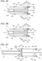
- the telescopic boom 14 transitions from the contracting state illustrated in Fig. 2A to the extending state illustrated in Fig. 1 by sequentially extending the booms in order from the boom disposed on the inner side.
- a plurality of intermediate booms may be provided.
- the distal end boom 141 includes a pair of cylinder pin receiving sections 141a and a pair of boom pin receiving sections 141b at its proximal end.
- the pair of cylinder pin receiving sections 141a are provided coaxially with each other at the proximal end of the distal end boom 141.
- the pair of cylinder pin receiving sections 141a can engage with and disengage from, respectively, the pair of cylinder coupling pins 454A and 454B provided in a cylinder member 32 (movable-side member) of a telescopic cylinder 3.
- the distal end boom 141 can move in the extending and shortening direction together with the cylinder member 32, with the pair of cylinder coupling pins 454A and 454B engaging with the pair of cylinder pin receiving sections 141a.
- the pair of boom pin receiving sections 141b are provided coaxially with each other near the cylinder pin receiving sections 141a.
- the boom pin receiving sections 141b support, respectively, the pair of boom coupling pins 15a.
- the pair of boom pin receiving sections 141b and the pair of cylinder pin receiving sections 141a are shifted from one another in axial direction of the telescopic boom 14, for convenience of explanation.
- the pair of boom pin receiving sections 141b and the pair of cylinder pin receiving sections 141a are aligned in the axial direction of the telescopic boom 14 and are provided at positions shifted in the circumferential direction of the telescopic boom 14.
- Each of the pair of boom coupling pins 15a couples the distal end boom 141 to the intermediate boom 142.
- the pair of boom coupling pins 15a moves inward (in direction from the distal ends toward the proximal ends of the boom coupling pins 15a), based on actuation of a boom coupling mechanism 46 that will be described later. It should be noted that a specific structure of the pair of boom coupling pins 15a will be described later.
- the pair of boom coupling pins 15b is inserted into and passes through, respectively, the pair of third boom pin receiving sections 142d.
- the pair of boom coupling pins 15b couples the intermediate boom 142 to the proximal end boom 143.
- the intermediate boom 142 and the proximal end boom 143 have boom pin emergency operation holes 143c and 143d at positions coaxial with the boom pin receiving sections of all the booms disposed inside in the state where the telescopic boom 14 contracts. Since the illustrated telescopic boom 14 has a single intermediate boom, the boom pin emergency operation holes 143c and 143d are provided only in the proximal end boom 143. However, when a plurality of intermediate booms are present, boom pin emergency operation holes may be provided in the intermediate booms at appropriate positions.
- boom coupling pins e.g., the boom coupling pins 15a
- he/she can access the boom coupling pins (e.g., the boom coupling pins 15a) from the outside of the telescopic boom 14 via the boom pin emergency operation holes 143c and 143d.
- the cylinder pin emergency operation holes 143b and the boom pin emergency operation holes 143c and 143d are provided within the same plane of the boom. Therefore, when manually operating cylinder coupling pins and boom coupling pins, the operator can do the work from the same direction.
- the actuator 2 is an actuator that extends and shortens the telescopic boom 14. As illustrated in Figs. 2A to 2E and 4 , the actuator 2 includes the telescopic cylinder 3 and a pin-moving mechanism 4. The actuator 2 is disposed in the inner space of the distal end boom 141 in the state where the telescopic boom 14 contracts (state illustrated in Fig. 2A ).
- the telescopic cylinder 3 includes a rod member 31 and the cylinder member 32.
- the telescopic cylinder 3 is used to move one or more booms coupled to the cylinder member 32 via the cylinder coupling pins 454A and 454B that will be described later.
- the pin-moving mechanism 4 includes the electric motor 41, a brake mechanism 42, a transmission mechanism 43, a position information detection device 44, a cylinder coupling mechanism 45, and the boom coupling mechanism 46, all of which are supported by a trunnion 40.
- the X direction coincide with the extending and shortening direction of the telescopic boom 14 mounted on the mobile crane 1.
- the +X direction is the extending direction, which is one of the extending and shortening direction.
- the -X direction is the contracting direction of the extending and contracting direction.
- the Z direction coincide with the upward and downward direction of the mobile crane 1, for example, in the state where the lifting angle of the telescopic boom 14 is 0°.
- the Y direction coincide with the vehicle width direction (right and left direction) of the mobile crane 1, for example, in a state where the telescopic boom 14 faces forward.
- the width direction or the right and left direction mean the Y direction in the orthogonal coordinate system (X, Y, Z), unless otherwise specified.
- the trunnion 40 is fixed to the cylinder member 32 of the telescopic cylinder 3.
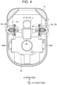
- the trunnion 40 supports the cylinder coupling mechanism 45 and the boom coupling mechanism 46, as illustrated in Fig. 4 .
- the trunnion 40 supports the electric motor 41, the brake mechanism 42, and the transmission mechanism 43.
- Fig. 4 is a cross-sectional view of the telescopic boom 14 and the pin-moving mechanism 4 taken along a plane (Z-Y plane) orthogonal to the extending or shortening direction of the telescopic boom 14. In Fig. 4 , some of the members are omitted for convenience of description. In Fig. 4 , the hatching indicating the cross section is also omitted.
- the trunnion 40 integrates the elements 41 to 46 into a single unit. Such a configuration contributes to compactness of the pin-moving mechanism 4, improved productivity, and enhanced system reliability.
- the cylinder coupling mechanism 45, the boom coupling mechanism 46, and the electric motor 41 are arranged side by side in the vertical direction, especially in the present embodiment. This arrangement contributes to the compactness of the pin-moving mechanism 4 in the extending and shortening direction (X direction) of the telescopic boom 14.
- the trunnion 40 has a support hole 401.
- the rod member 31 of the telescopic cylinder 3 is inserted into and passes through the support hole 401 in the X direction.
- the trunnion 40 is fixed to the proximal end (-X-directional end) of the cylinder member 32 of the telescopic cylinder 3. The trunnion 40 thereby can move together with the cylinder member 32.
- the electric motor 41 is supported by the trunnion 40 (see Fig. 4 ). More specifically, the electric motor 41 is supported by the upper side of the trunnion 40, with the output shaft thereof disposed in parallel to the extending and shortening direction (X direction) of the telescopic boom 14. As illustrated in Fig. 7A , the electric motor 41 is connected to a speed reducer 431. The electric motor 41 is connected to, for example, a power supply device (not illustrated) provided on the turning table 12 via a power supply cable.
- the brake mechanism 42 applies braking force to the electric motor 41.
- the brake mechanism 42 prevents the output shaft of the electric motor 41 from rotating when the electric motor 41 stops. As a result, the state of the pin-moving mechanism 4 is maintained when the electric motor 41 stops.
- the speed reducer 431 and the brake mechanism 42 are provided coaxially with the electric motor 41.
- the brake mechanism 42 is activated in the state where the cylinder coupling mechanism 45 shortens or in the state where the boom coupling mechanism 46 shortens, which will be described later, thereby maintaining the state of the cylinder coupling mechanism 45 or the boom coupling mechanism 46.
- the state of the brake mechanism 42 is switched by a control section. Alternatively, the state of the brake mechanism 42 may be switched based on operator's operation.
- the transmission mechanism 43 transmits the power of the electric motor 41 to the cylinder coupling mechanism 45 and the boom coupling mechanism 46.
- the transmission mechanism 43 has the speed reducer 431 and a transmission shaft 432.
- the information regarding the positions of the pair of cylinder coupling pins 454A and 454B and the pair of boom coupling pins 15a and 15b refers to, for example, a movement amount of the pair of cylinder coupling pins 454A and 454B or the pair of boom coupling pins 15a and 15b from reference positions.
- the positions of the pair of cylinder coupling pins 454A and 454B illustrated in Fig. 7A correspond to the reference positions of the cylinder coupling pins 454A and 454B.
- the positions of the pair of boom coupling pins 15a illustrated in Fig. 8A correspond to the reference positions of the boom coupling pins 15a.
- the cylinder coupling mechanism 45 is activated based on the power of the electric motor 41 and transitions between the extending state (see Fig. 7A ) and the contracting state (see Fig. 7C ).
- the operation in which the cylinder coupling mechanism 45 transitions from the extending state to the contracting state corresponds to a removal operation to be performed by the cylinder coupling mechanism 45.
- the operation in which the cylinder coupling mechanism 45 transitions from the contracting state to the extending state corresponds to an insertion operation to be performed by the cylinder coupling mechanism 45.
- the pair of cylinder coupling pins 454A and 454B engages with the pair of cylinder pin receiving sections 141a of a boom (e.g., distal end boom 141). In this engaging state, the boom is coupled to the cylinder member 32.
- the cylinder coupling mechanism 45 includes the switch gear 450, a first transmission mechanism 451, the pair of cylinder coupling pins 454A and 454B, and a first biasing mechanism 455.
- the switch gear 450 is externally fitted into and fixed to the transmission shaft 432 and selectively transmits the power of the electric motor 41 to a coupling mechanism, which is one of the cylinder coupling mechanism 45 and the boom coupling mechanism 46.
- a direction (direction indicated by arrow A 1 in Fig. 7A ) in which the switch gear 450 rotates when the cylinder coupling mechanism 45 transitions from the extending state to the contracting state is defined as a first rotation direction of the switch gear 450.
- a direction (direction indicated by arrow A 2 in Fig. 7C ) in which the switch gear 450 rotates when the cylinder coupling mechanism 45 transitions from the contracting state to the extending state is defined as a second rotation direction of the switch gear 450.
- the first transmission mechanism 451 is formed of a rack bar or a gear, for example.
- the first transmission mechanism 451 transmits driving force related to the rotation of the switch gear 450 to the cylinder coupling pins 454A and 454B.
- the pair of cylinder coupling pins 454A and 454B have respective central axes coinciding with and are coaxial with each other in the right and left direction. Each of the pair of cylinder coupling pins 454A and 454B is supported by the trunnion 40.
- the pair of cylinder coupling pins 454A and 454B is configured to be movable in its own axial direction, based on the power of the electric motor 41 or the biasing force of the first biasing mechanism 455.
- the first transmission mechanism 451 transmits driving force for moving the cylinder coupling pins 454A and 454B inward to the cylinder coupling pins 454A and 454B.
- the cylinder coupling mechanism 45 turns into the contracting state.
- the cylinder coupling mechanism 45 transmits the driving force for moving the cylinder coupling pins 454A and 454B outward to the cylinder coupling pins 454A and 454B. As a result, the cylinder coupling mechanism 45 turns into the extending state.
- the boom coupling mechanism 46 When being in the extending state, the boom coupling mechanism 46 can engage with boom coupling pins (e.g., the pair of boom coupling pins 15a).
- the boom coupling mechanism 46 transitions from the extending state to the contracting state while engaging with the boom coupling pins, thereby disengaging the boom coupling pins from the boom.
- the boom coupling pins 15a will be described as an example of the boom coupling pins.
- the boom coupling pins may also be the boom coupling pins 15b.
- the boom coupling mechanism 46 transitions from the contracting state to the extending state while engaging with the boom coupling pins 15a, thereby causing the boom coupling pins 15a to engage with the outer boom.
- the boom coupling mechanism 46 includes the switch gear 450 and a second transmission mechanism 461.
- the switch gear 450 is a gear shared by the cylinder coupling mechanism 45.
- the second transmission mechanism 461 is formed of a rack bar or a gear, for example. While engaging with the boom coupling pins 15a, the second transmission mechanism 461 transmits the driving force related to the rotation of the switch gear 450 to the pair of boom coupling pins 15a. In short, the second transmission mechanism 461 simultaneously moves the pair of boom coupling pins 15a.
- each boom coupling pin 15a is configured to be movable in the axial direction.
- Fig. 5A illustrates a state where a boom coupling pin 15a is located on the outermost side (at one end in the movement stroke in the axial direction). The state where the boom coupling pin 15a is located on the outermost side is also referred to as the insertion state of the boom coupling pin 15a.
- Fig. 5B illustrates a state where the boom coupling pin 15a is located at the innermost side (at the other end in the movement stroke in the axial direction).
- the state where the boom coupling pin 15a is located at the innermost side is also referred to as the removal state of the boom coupling pin 15a.
- each of the inner booms (the distal end boom 141 and the intermediate boom 142 in the present embodiment) which is disposed inside the proximal end boom 143 is provided with a pair of boom coupling pins. All of the boom coupling pins have substantially the same configuration as the boom coupling pins 15a.
- the right boom coupling pin 15a will be described.
- the configuration of the left boom coupling pin 15a of the pair of boom coupling pins 15a is substantially the same as that of the boom coupling pins 15a.
- the pin main body 150 which is a substantially cylindrical member, is configured to be movable in the axial direction.
- the pin main body 150 can also be regarded as the boom coupling pin.
- the pin main body 150 has a first storage section 150a in its half portion at the distal end (on the outer side).
- the distal end (outer end) of the first storage section 150a is exposed from a distal end surface (outer end surface) of the pin main body 150.
- the central axis of the first storage section 150a is parallel to the axial direction and coincides with the central axis of the pin main body 150.
- the pin main body 150 has a second storage section 150b in its half portions at the proximal end (on the inner side).
- the central axis of the second storage section 150b is parallel to the axial direction and coincides with the central axis of the pin main body 150.
- the central axis of the second storage section 150b coincides with the central axis of the first storage section 150a.
- the first storage section 150a is separated from the second storage section 150b by a partition section 150c.
- the partition section 150c which has a planar shape, has a pin-side through-hole 150d formed across the partition section 150c in the axial direction.
- the central axis of the pin-side through-hole 150d coincides with the central axes of the first storage section 150a and the second storage section 150b.
- the slit 150e is provided on the upper side of the pin main body 150.
- the slit 150f is provided on the lower side of the pin main body 150.
- the slit 150e and the slit 150f are formed opposite each other in the vertical direction.
- the pin main body 150 having the above configuration is held by the boom pin receiving section 141b of the distal end boom 141.
- the boom pin receiving section 141b is formed of a cylindrical sleeve fixed to the distal end boom 141.
- the boom pin receiving section 141b is fixed to the distal end boom 141 with welding.
- Support members 144 are fixed to the boom pin receiving section 141b.
- Each of the support members 144 which is a planar member extending in the vertical direction, is fixed to the boom pin receiving section 141b via a fastening component, such as a bolt. More specifically, the support members 144, each of which is formed of a single planar member, are fixed to the boom pin receiving section 141b by fastening components 144c (bolts in the illustrated case) inserted into and passing through the upper portion and the lower portion.
- Each support member 144 is a member that supports the pin main body 150 with respect to the boom. Each support member 144 is also a member that guides the movement of the pin main body 150 in the axial direction.
- the support members 144 are inserted into and pass through the slits 150e and 150f of the pin main body 150 in the upward and downward direction.
- the width dimension of the support members 144 is slightly smaller than the width dimension of the slits 150e and 150f. The movement of the pin main body 150 in the axial direction is guided by the engagement between the support members 144 and the slits 150e and 150f.
- the support members 144 are inserted into and pass through the slits 150e and 150f in the upward and downward direction.
- Such a configuration contributes to compactness of a structure that supports the boom coupling pin 15a on the boom pin receiving section 141b.
- the fastening components 144c that fix the support members 144 to the boom pin receiving sections 141b are provided above and below the pin main body 150. Therefore, when the boom coupling mechanism 46 engages with the latch claw section 154 of the boom coupling pin 15a from the extending or shortening direction (X direction) in the state illustrated in Fig. 5A , the boom coupling mechanism 46 and the fastening component 144c do not interfere with each other.
- the interference can be suppressed without provision of a space used to avoid the interference between the boom coupling mechanism 46 and the fastening component 144c in the extending and shortening direction.
- the boom coupling pins 15a and 15b are attached to the telescopic boom 14 from the inside of the telescopic boom 14. Therefore, it is unnecessary to disassemble the telescopic boom 14 during the work in which the boom coupling pins 15a and 15b are attached to the telescopic boom 14.
- Each support member 144 has a boss section 144a at its center in the vertical direction.
- the boss section 144a protrudes from one side surface (outer-side surface) of each support member 144 toward one side (outer side) of each support member 144 in the plate thickness direction.
- the plate thickness direction of each support member 144 coincide with the axial direction of the pin main body 150 and the vehicle width direction of the mobile crane 1.
- the boss section 144a has a support-side screw hole 144b on its distal side.
- the central axis of the support-side screw hole 144b coincides with the central axis of the pin-side through-hole 150d.
- the inner circumferential surface of the support-side screw hole 144b is provided with a female screw section.
- the boss section 144a is disposed on a proximal end of the second storage section 150b of the pin main body 150, in the state where the boom coupling pin 15a is inserted (in the state illustrated in Fig. 5A ).
- the boss section 144a configured above is a member for use in positioning (guiding) the first coil spring 151 and the second coil spring 152 as described later and is also a member for use in storing a nut 153b of the manual operation member 153 inside.
- Each of the first coil spring 151 and the second coil spring 152 is a biasing member for use in causing the boom coupling mechanism 46 to transition from the contracting state to the extending state during regular operation of the boom coupling mechanism 46.
- each of the first coil spring 151 and the second coil spring 152 is a biasing member that causes the boom coupling pin 15a to transition from the removal state to the insertion state during the regular operation of the boom coupling mechanism 46.
- the first coil spring 151 and the second coil spring 152 are disposed in the second storage section 150b of the pin main body 150.
- the outer diameter of the first coil spring 151 is larger than the outer diameter of the second coil spring 152.
- the second coil spring 152 is disposed on the inner side of the first coil spring 151.
- first coil spring 151 and the second coil spring 152 are disposed between each support member 144 and the pin main body 150. More specifically, the distal ends (one end in the axial direction) of the first coil spring 151 and the second coil spring 152 are in contact with the pin main body 150 (more specifically, the partition section 150c).
- the outer circumferential surface of the distal end of the first coil spring 151 is held by the inner circumferential surface of a depression section 150g provided at the proximal end of the pin main body 150. With such a configuration, the compression of the first coil spring 151 is guided by the inner circumferential surface of the depression section 150g.
- the outer circumferential surface of the distal end of the second coil spring 152 is held by the first coil spring 151.
- the proximal ends (other ends in the axial direction) of the first coil spring 151 and the second coil spring 152 are in contact with the support members 144.
- the proximal ends of the first coil spring 151 and the second coil spring 152 are disposed so as to surround the boss section 144a.
- the first coil spring 151 and the second coil spring 152 are positioned by the boss section 144a.
- the manual operation member 153 is a member to be operated by the operator during the manual operation.
- the manual operation member 153 is operated, for example, with a manual operation tool 5 to be used by an operator.
- the manual operation member 153 is inserted into and passes through the pin main body 150 and disposed coaxially with the pin main body 150.
- the pin main body 150 moves in the removal direction (toward the other side in the axial direction) together with the manual operation member 153, so that the coupling between the adjacent booms is released. More specifically, when the manual operation member 153 is rotated, the manual operation member 153 presses the pin main body 150 in the removal direction. The pin main body 150 then moves in the removal direction to release the coupling between adjacent booms.
- the manual operation member 153 which is a member that presses the pin main body 150 in the removal direction during the manual operation, is continuously integrated into the boom coupling pin 15a.
- the manual operation member 153 is continuously supported by the boom coupling pin 15a.
- the manual operation tool 5 is a socket wrench, for example.
- the length of the socket wrench may be adjusted as appropriate by an extension bar in accordance with the position of the boom coupling pin to be operated.
- the type of the manual operation tool may be determined as appropriate in accordance with the shape of the head section of the manual operation member.
- the manual operation member 153 includes a bolt 153a and the nut 153b.
- the bolt 153a includes a head section 153c and a screw shaft section 153d.
- the outer circumferential surface of the screw shaft section 153d is provided with a male screw section.
- the screw shaft section 153d is inserted into and passes through the pin-side through-hole 150d and the support-side screw hole 144b.
- the central axis of the screw shaft section 153d coincides with the central axes of the pin-side through-hole 150d and the support-side screw hole 144b.
- the male screw section of the screw shaft section 153d is screwed into the female screw section of the support-side screw hole 144b.
- One end (outer end) of the screw shaft section 153d in the axial direction protrudes toward one side (right side in Figs. 5A and 5B ) in the axial direction from the pin-side through-hole 150d (partition section 150c).
- the end (outer end) of the screw shaft section 153d in the axial direction is disposed in the first storage section 150a of the pin main body 150.
- the other end (inner end) of the screw shaft section 153d in the axial direction protrudes toward the other side (inner side or left side in Figs. 5A and 5B ) in the axial direction from the support-side screw hole 144b (the boss section 144a of each support member 144).
- the head section 153c is provided at one end (outer end) of the screw shaft section 153d in the axial direction.
- the head section 153c is provided on the one side (the right side in Figs. 5A and 5B ) of the pin-side through-hole 150d (partition section 150c) in the axial direction.
- the head section 153c is disposed in the first storage section 150a of the pin main body 150.
- the head section 153c which corresponds to an example of a pressing section, is a member that presses the pin main body 150 in the removal direction during the manual operation.
- the nut 153b which is a so-called double nut, is fixed to the other end (inner end) of the screw shaft section 153d in the axial direction.
- the nut 153b is disposed on the other side (the left side in Figs. 5A and 5B ) of the support-side screw hole 144b (the boss section 144a of each support member 144) in the axial direction.
- the nut 153b is disposed on the inner side of the boss section 144a (left side in Figs. 5A and 5B ).
- the manual operation member 153 having the above configuration constitutes, together with the support-side screw hole 144b, a conversion mechanism that can convert its own rotational motion into linear motion in the axial direction.
- the manual operation member 153 moves in a predetermined direction of the axial direction.
- the latch claw section 154 is fixed to the proximal end of the pin main body 150.
- the latch claw section 154 is configured to be able to be coupled to the boom coupling mechanism 46.
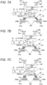
- Fig. 8A is a schematic view illustrating the extending state of the boom coupling mechanism 46 and the state where the pair of boom coupling pins 15a engages with the pair of first boom pin receiving sections 142b of the intermediate boom 142.
- Fig. 8B is a schematic view illustrating a state in the middle of the transition from the extending state to the contracting state of the boom coupling mechanism 46.
- Fig. 8C is a schematic view illustrating the contracting state of the boom coupling mechanism 46 and the state where the pair of boom coupling pins 15a has disengaged from the pair of first boom pin receiving sections 142b of the intermediate boom 142.
- the extending state of the boom coupling mechanism 46 illustrated in Fig. 8A is related to the state of the boom coupling mechanism 46 in Fig. 2A .
- the state of the boom coupling pins 15a related to the extending state of the boom coupling mechanism 46 illustrated in Fig. 8A is the insertion state.
- Fig. 5A illustrates the boom coupling pin 15a in the insertion state.
- the state of the boom coupling mechanism 46 illustrated in Fig. 8B is related to the state in the middle of the transition from the state of the boom coupling mechanism 46 illustrated in Fig. 2A to the state of the boom coupling mechanism 46 illustrated in Fig. 2B .
- the contracting state of the boom coupling mechanism 46 illustrated in Fig. 8C is related to the state of the boom coupling mechanism 46 illustrated in Fig. 2B .
- the state of the boom coupling pins 15a is related to the contracting state of the boom coupling mechanism 46 illustrated in Fig. 8C is the removal state.
- the boom coupling mechanism 46 transitions between the extending state and the contracting state, based on the power of the electric motor 41.
- the position of the switch gear 450 illustrated in Fig. 8A is defined as the reference position of the switch gear 450.
- the control section (not illustrated) drives the electric motor 41 in the direction opposite to the direction in which the cylinder coupling mechanism 45 is activated.
- the power of the electric motor 41 is transmitted to the pair of boom coupling pins 15a via the switch gear 450 and the second transmission mechanism 461.
- the latch claw section 154 of the boom coupling pin 15a engages with the second transmission mechanism 461.
- the pin main body 150 moves leftward from the position illustrated in Fig. 5A .
- the pin main body 150 moves leftward against the biasing force of the first coil spring 151 and the second coil spring 152.
- the manual operation member 153 does not move from the position illustrated in Fig. 5A .
- the position information detection device 44 detects that the pair of boom coupling pins 15a has disengaged from the pair of first boom pin receiving sections 142b of the intermediate boom 142 and moved to predetermined positions (e.g., the positions illustrated in Fig. 8C ). Based on the detection result, the control section then stops the operation of the electric motor 41.
- the position information detection device 44 detects that the pair of boom coupling pins 15a has engaged with the pair of first boom pin receiving sections 142b of the intermediate boom 142 and moved to predetermined positions (e.g., the positions illustrated in Fig. 8C ). The detection result is used to control the subsequent operation of the actuator 2.
- the operator can perform a manual operation to cause the boom coupling mechanism 46 to transition from the extending state to the contracting state.
- the operator can perform the manual operation to cause the pair of boom coupling pins 15a to transition from the insertion state to the removal state.
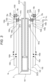
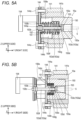
- the operator inserts the manual operation tool 5 (see Figs. 3 and 5A ) into a boom pin emergency operation hole 143c (see Fig. 3 ) from the outside of the telescopic boom 14.
- the operator then causes the manual operation tool 5 to engage with the manual operation member 153 in the boom coupling pin 15a. More specifically, the manual operation tool 5 engages with the head section 153c in the manual operation member 153.
- the manual operation member 153 rotates together with the manual operation tool 5.
- the manual operation member 153 moves in an axial direction (toward the left side in Fig. 5A , or in a direction in which the boom coupling pin 15a is to be removed), based on the screwing between the screw shaft section 153d of the manual operation member 153 and the support-side screw hole 144b of the support member 144.
- the head section 153c presses the pin main body 150 (more specifically, the partition section 150c) in the direction in which the boom coupling pin 15a is to be removed.
- the pin main body 150 moves in the direction (toward the left side in Fig. 5A ) in which the boom coupling pin 15a is to be removed, against the biasing force of the first coil spring 151 and the second coil spring 152.
- the depth ends (one end in the axial direction, or the right end in Figs. 5A and 5B ) of the slits 150e and 150f of the pin main body 150 come into contact with the support members 144 in the axial direction.
- the boom coupling pins 15a turn into the removal state illustrated in Fig. 5B .
- the engagement between each boom coupling pin 15a and the intermediate boom 142 is thereby released.
- the movement of the pin main body 150 in the insertion direction is restricted by the contact between the depth end of each of the slits 150e and 150f and the support members 144.
- the right boom coupling pin 15a is connected to the left boom coupling pin 15a via the boom coupling mechanism 46.
- the other boom coupling pin 15a also moves in the removal direction in synchronization with the one boom coupling pin 15a.
- both the right boom coupling pin 15a and the left boom coupling pin 15a simultaneously transition from the insertion state to the removal state.
- the mobile crane according to the present embodiment also includes a mechanism (cylinder pin manual operation mechanism) for releasing the coupling between the telescopic cylinder 3 and the boom in response to manual operation.
- the operator can operate the cylinder pin manual operation mechanism with a tool that has been inserted into the cylinder pin emergency operation hole 143b, thereby successfully releasing the coupling between the telescopic cylinder 3 and each boom.
- the cylinder pin emergency operation hole 143b and the boom pin emergency operation holes 143c and 143d are provided on the same surface in the boom.
- the operator can perform the manual operation of releasing the coupling between the telescopic cylinder 3 and each boom and the manual operation of releasing the coupling between the booms from the same direction (i.e., the direction indicated by arrow A 3 in Fig. 3 ).
- Such a configuration contributes to improvement in operability of manual operation.
- the operator can perform a manual operation to cause the boom coupling pins 15a to transition from the insertion state to the removal state, thereby successfully manually releasing the coupling between adjacent booms.
- the manual operation member 153 is disposed coaxially with the pin main body 150.
- the force by which the pin main body 150 would be angled is less likely to act on the pin main body 150.
- the present invention is not limited to mobile cranes and is applicable to various work machines (e.g., high-place work vehicles) equipped with telescopic booms.
Landscapes
- Engineering & Computer Science (AREA)
- Mechanical Engineering (AREA)
- Jib Cranes (AREA)
Abstract
Description
- The present invention relates to a work machine equipped with a telescopic boom.
- Patent Literature 1 discloses a mobile crane that includes: a telescopic boom in which a plurality of booms are stacked in a nested structure; and a hydraulic actuator (telescopic cylinder) that extends the telescopic boom.
- The adjacent booms are coupled together with coupling pins. Once the coupling between the booms with the coupling pins is released, the booms are movable relative to one another in the extending and shortening direction (those booms are referred to below as the movable booms) .
- The actuator is coupled to the movable booms via coupling pins. When the actuator moves in the extending and shortening direction in this state, the boom that is movable together with the actuator moves so that the telescopic boom extends and shortens.
- Patent Literature 1:
JP 2012-96928 A - If a mechanism for coupling adjacent booms breaks in a crane as described above, the crane may fail to release the coupling between the booms, in which case the telescopic boom can no longer contract.
- An object of the present invention is to provide a work machine equipped with a mechanism by which the coupling between adjacent booms can be manually released.
- An aspect of a work machine according to the present invention includes:
- a plurality of booms that extend and shorten by power of an actuator;
- a boom coupling pin that is moved in an insertion direction by a spring to turn into an insertion state where adjacent ones of the booms make a coupling with each other and that is moved in a removal direction by power of a motor to turn into a removal state where the coupling is released, the boom coupling pin being supported by the booms; and
- a manual operation member that is inserted into and passes through the boom coupling pin, the manual operation member being disposed coaxially with the boom coupling pin, in which
- when the manual operation member is rotated based on an operator's manual operation, the boom coupling pin moves in the removal direction together with the manual operation member to release the coupling between the adjacent booms.
- The present invention can provide a work machine equipped with a mechanism by which the coupling between adjacent booms can be manually released.
-
-
Fig. 1 is a schematic view of a mobile crane according to an embodiment. -
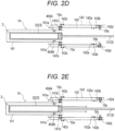
Fig. 2A is a schematic view for illustrating a structure and extending/shortening movement of a telescopic boom. -
Fig. 2B is the schematic view for illustrating the structure and extending/shortening movement of the telescopic boom. -
Fig. 2C is the schematic view for illustrating the structure and extending/shortening movement of the telescopic boom. -
Fig. 2D is the schematic view for illustrating the structure and extending/shortening movement of the telescopic boom. -
Fig. 2E is the schematic view for illustrating the structure and extending/shortening movement of the telescopic boom. -
Fig. 3 is a schematic view for illustrating the structure of the telescopic boom. -
Fig. 4 is a cross-sectional view of a pin-moving mechanism in a state where a boom coupling mechanism contracts. -
Fig. 5A is an enlarged cross-sectional view of section X inFig. 4 , which illustrates a state where a boom coupling pin is inserted. -
Fig. 5B is an enlarged cross-sectional view of section X inFig. 4 , which illustrates a state where the boom coupling pin is removed by a manual operation. -
Fig. 6 is a perspective view of the boom coupling pin. -
Fig. 7A is a schematic view for illustrating an operation of the cylinder coupling mechanism. -
Fig. 7B is a schematic view for illustrating the operation of the cylinder coupling mechanism. -
Fig. 7C is a schematic view for illustrating the operation of the cylinder coupling mechanism. -
Fig. 8A is a schematic view for illustrating the operation of the boom coupling mechanism. -
Fig. 8B is a schematic view for illustrating the operation of the boom coupling mechanism. -
Fig. 8C is a schematic view for illustrating the operation of the boom coupling mechanism. - Hereinafter, an example of an embodiment of the present invention will be described in detail with reference to the accompanying drawings. It should be noted that a crane according to the embodiment which will be described below corresponds to an example of a work machine according to the present invention, and the present invention is not limited to the embodiments described below.
- An outline of a mobile crane 1 according to the present embodiment will be described with reference to
Fig. 1 andFigs. 2A to 2E . - The mobile crane is, for example, a rough terrain crane, an all-terrain crane, a truck crane, or a truck loader crane. However, the work machine is not limited to such a mobile crane and may be any other work machine (e.g., a high-place work vehicle) equipped with a telescopic boom.
- The mobile crane 1 includes a
telescopic boom 14 and anactuator 2. Thetelescopic boom 14 includes a plurality of booms that have been assembled so as to be able to extend and shorten. Adjacent booms are coupled together byboom coupling pins - The
actuator 2 moves booms in the extending or shortening direction when extending/shortening thetelescopic boom 14. In this case, theactuator 2 is coupled to a boom being moved viacylinder coupling pins - During the extending or shortening operation of the
telescopic boom 14, the boom coupling pins 15a and 15b are moved by the power of anelectric motor 41 to release the coupling between the adjacent booms. In this case, if any trouble occurs in theelectric motor 41, theelectric motor 41 may be unable to move the boom coupling pins 15a and 15b, thereby failing to release the coupling between the adjacent booms. For this reason, the mobile crane 1 includes a unit (releasing unit) that releases the coupling between the adjacent booms by allowing the boom coupling pins 15a and 15b to be manually moved. Hereinafter, the configuration of the mobile crane 1 according to the present embodiment will be specifically described. - As illustrated in
Figs. 1 and2A to 2E , the mobile crane 1 includes a travelingbody 10, a turning table 12, thetelescopic boom 14, theactuator 2, awire rope 16, and ahook 17. - The turning table 12 is provided over the traveling
body 10. Thetelescopic boom 14 is fixed at its proximal end to the turning table 12 and can rise/fall and extend/shorten. Theactuator 2 extends or shortens thetelescopic boom 14. Thewire rope 16 is supported by thetelescopic boom 14 and hangs down from a distal end of thetelescopic boom 14. Thehook 17 is provided at a distal end of thewire rope 16. - Next, the
telescopic boom 14 will be described. Thetelescopic boom 14 has a plurality of booms that have been assembled together in a telescopic manner. Specifically, the plurality of booms include adistal end boom 141, anintermediate boom 142, and aproximal end boom 143, which are disposed in order from the inner side. - The
telescopic boom 14 transitions from the contracting state illustrated inFig. 2A to the extending state illustrated inFig. 1 by sequentially extending the booms in order from the boom disposed on the inner side. A plurality of intermediate booms may be provided. - The
distal end boom 141 includes a pair of cylinderpin receiving sections 141a and a pair of boompin receiving sections 141b at its proximal end. The pair of cylinderpin receiving sections 141a are provided coaxially with each other at the proximal end of thedistal end boom 141. The pair of cylinderpin receiving sections 141a can engage with and disengage from, respectively, the pair of cylinder coupling pins 454A and 454B provided in a cylinder member 32 (movable-side member) of atelescopic cylinder 3. - The
distal end boom 141 can move in the extending and shortening direction together with thecylinder member 32, with the pair of cylinder coupling pins 454A and 454B engaging with the pair of cylinderpin receiving sections 141a. - The pair of boom
pin receiving sections 141b are provided coaxially with each other near the cylinderpin receiving sections 141a. The boompin receiving sections 141b support, respectively, the pair ofboom coupling pins 15a. In the illustrated case, the pair of boompin receiving sections 141b and the pair of cylinderpin receiving sections 141a are shifted from one another in axial direction of thetelescopic boom 14, for convenience of explanation. However, the pair of boompin receiving sections 141b and the pair of cylinderpin receiving sections 141a are aligned in the axial direction of thetelescopic boom 14 and are provided at positions shifted in the circumferential direction of thetelescopic boom 14. - Each of the pair of boom coupling pins 15a couples the
distal end boom 141 to theintermediate boom 142. The pair of boom coupling pins 15a moves inward (in direction from the distal ends toward the proximal ends of the boom coupling pins 15a), based on actuation of aboom coupling mechanism 46 that will be described later. It should be noted that a specific structure of the pair ofboom coupling pins 15a will be described later. - In a state where the
distal end boom 141 is coupled to theintermediate boom 142 by the pair ofboom coupling pins 15a, the boom coupling pins 15a are inserted into and pass through both the boompin receiving sections 141b of thedistal end boom 141 and first boompin receiving sections 142b or the second boompin receiving sections 142c of theintermediate boom 142 so as to bridge therebetween. In short, the pair ofboom coupling pins 15a can engage with or disengage from, respectively, the first boompin receiving sections 142b or the second boompin receiving sections 142c of theintermediate boom 142. - The
intermediate boom 142 has, at its proximal end, a pair of cylinderpin receiving sections 142a, the pair of first boompin receiving sections 142b, and a pair of third boompin receiving sections 142d and also has, at its distal end, the pair of second boompin receiving sections 142c. - In the illustrated case, the pair of first boom
pin receiving sections 142b and the pair of cylinderpin receiving sections 142a are shifted from one another in the axial direction of thetelescopic boom 14, for convenience of explanation. However, the pair of first boompin receiving sections 142b and the pair of cylinderpin receiving sections 142a are aligned in the axial direction of thetelescopic boom 14 and are provided at positions shifted in the circumferential direction of thetelescopic boom 14. - The pair of boom coupling pins 15b is inserted into and passes through, respectively, the pair of third boom
pin receiving sections 142d. The pair of boom coupling pins 15b couples theintermediate boom 142 to theproximal end boom 143. - The pair of second boom
pin receiving sections 142c are provided coaxially with each other at the distal end of theintermediate boom 142. The pair ofboom coupling pins 15a is inserted into and passes through, respectively, the pair of second boompin receiving sections 142c. - As illustrated in
Fig. 3 , theintermediate boom 142 has a pair of cylinder pinemergency operation holes 142e at positions coaxial with the pair of cylinderpin receiving sections 141a of thedistal end boom 141 in the state where thetelescopic boom 14 contracts. Theproximal end boom 143 has a pair of cylinder pinemergency operation holes 143a at positions coaxial with the pair of cylinderpin receiving sections 141a of thedistal end boom 141 in the state where thetelescopic boom 14 contracts. - The
proximal end boom 143 has a pair of cylinder pin emergency operation holes 143b at positions coaxial with the pair of cylinderpin receiving sections 142a of theintermediate boom 142 in the state where thetelescopic boom 14 contracts. - When an operator performs a manual operation of manually moving the pair of cylinder coupling pins 454A and 454B, he/she can access, from the outside of the
telescopic boom 14 via the cylinder pinemergency operation holes pin receiving sections 141a of thedistal end boom 141 or the pair of cylinderpin receiving sections 142a of theintermediate boom 142. - Furthermore, the
intermediate boom 142 and theproximal end boom 143 have boom pin emergency operation holes 143c and 143d at positions coaxial with the boom pin receiving sections of all the booms disposed inside in the state where thetelescopic boom 14 contracts. Since the illustratedtelescopic boom 14 has a single intermediate boom, the boom pin emergency operation holes 143c and 143d are provided only in theproximal end boom 143. However, when a plurality of intermediate booms are present, boom pin emergency operation holes may be provided in the intermediate booms at appropriate positions. - When the operator performs a manual operation of manually moving boom coupling pins (e.g., the boom coupling pins 15a), he/she can access the boom coupling pins (e.g., the boom coupling pins 15a) from the outside of the
telescopic boom 14 via the boom pin emergency operation holes 143c and 143d. - In the present embodiment, the cylinder pin emergency operation holes 143b and the boom pin emergency operation holes 143c and 143d are provided within the same plane of the boom. Therefore, when manually operating cylinder coupling pins and boom coupling pins, the operator can do the work from the same direction.
- The
actuator 2 is an actuator that extends and shortens thetelescopic boom 14. As illustrated inFigs. 2A to 2E and4 , theactuator 2 includes thetelescopic cylinder 3 and a pin-movingmechanism 4. Theactuator 2 is disposed in the inner space of thedistal end boom 141 in the state where thetelescopic boom 14 contracts (state illustrated inFig. 2A ). - The
telescopic cylinder 3 includes arod member 31 and thecylinder member 32. Thetelescopic cylinder 3 is used to move one or more booms coupled to thecylinder member 32 via the cylinder coupling pins 454A and 454B that will be described later. - The pin-moving
mechanism 4 includes theelectric motor 41, abrake mechanism 42, atransmission mechanism 43, a positioninformation detection device 44, acylinder coupling mechanism 45, and theboom coupling mechanism 46, all of which are supported by atrunnion 40. - Hereinafter, individual members constituting the
actuator 2 will be described with reference to a state where the members are integrated into theactuator 2. In the description of theactuator 2, an orthogonal coordinate system (X, Y, Z) is used. - In the orthogonal coordinate system, the X direction coincide with the extending and shortening direction of the
telescopic boom 14 mounted on the mobile crane 1. The +X direction is the extending direction, which is one of the extending and shortening direction. The -X direction is the contracting direction of the extending and contracting direction. When the turning angle of thetelescopic boom 14 is 0° and the lifting angle of thetelescopic boom 14 is 0° (in the fully folded state), the +X-directional side coincides with the front side of the mobile crane 1. When the turning angle of thetelescopic boom 14 is 0° and the lifting angle of thetelescopic boom 14 is 0°, the -X-directional side coincides with the rear side of the mobile crane 1. - The Z direction coincide with the upward and downward direction of the mobile crane 1, for example, in the state where the lifting angle of the
telescopic boom 14 is 0°. The Y direction coincide with the vehicle width direction (right and left direction) of the mobile crane 1, for example, in a state where thetelescopic boom 14 faces forward. Hereinafter, the width direction or the right and left direction mean the Y direction in the orthogonal coordinate system (X, Y, Z), unless otherwise specified. - The
trunnion 40 is fixed to thecylinder member 32 of thetelescopic cylinder 3. Thetrunnion 40 supports thecylinder coupling mechanism 45 and theboom coupling mechanism 46, as illustrated inFig. 4 . In addition, thetrunnion 40 supports theelectric motor 41, thebrake mechanism 42, and thetransmission mechanism 43.Fig. 4 is a cross-sectional view of thetelescopic boom 14 and the pin-movingmechanism 4 taken along a plane (Z-Y plane) orthogonal to the extending or shortening direction of thetelescopic boom 14. InFig. 4 , some of the members are omitted for convenience of description. InFig. 4 , the hatching indicating the cross section is also omitted. - The
trunnion 40 integrates theelements 41 to 46 into a single unit. Such a configuration contributes to compactness of the pin-movingmechanism 4, improved productivity, and enhanced system reliability. In addition, thecylinder coupling mechanism 45, theboom coupling mechanism 46, and theelectric motor 41 are arranged side by side in the vertical direction, especially in the present embodiment. This arrangement contributes to the compactness of the pin-movingmechanism 4 in the extending and shortening direction (X direction) of thetelescopic boom 14. - The
trunnion 40 has asupport hole 401. Therod member 31 of thetelescopic cylinder 3 is inserted into and passes through thesupport hole 401 in the X direction. Thetrunnion 40 is fixed to the proximal end (-X-directional end) of thecylinder member 32 of thetelescopic cylinder 3. Thetrunnion 40 thereby can move together with thecylinder member 32. - The
electric motor 41 is supported by the trunnion 40 (seeFig. 4 ). More specifically, theelectric motor 41 is supported by the upper side of thetrunnion 40, with the output shaft thereof disposed in parallel to the extending and shortening direction (X direction) of thetelescopic boom 14. As illustrated inFig. 7A , theelectric motor 41 is connected to aspeed reducer 431. Theelectric motor 41 is connected to, for example, a power supply device (not illustrated) provided on the turning table 12 via a power supply cable. - The
brake mechanism 42 applies braking force to theelectric motor 41. Thebrake mechanism 42 prevents the output shaft of theelectric motor 41 from rotating when theelectric motor 41 stops. As a result, the state of the pin-movingmechanism 4 is maintained when theelectric motor 41 stops. Thespeed reducer 431 and thebrake mechanism 42 are provided coaxially with theelectric motor 41. - More specifically, the
brake mechanism 42 is activated in the state where thecylinder coupling mechanism 45 shortens or in the state where theboom coupling mechanism 46 shortens, which will be described later, thereby maintaining the state of thecylinder coupling mechanism 45 or theboom coupling mechanism 46. The state of thebrake mechanism 42 is switched by a control section. Alternatively, the state of thebrake mechanism 42 may be switched based on operator's operation. - The
transmission mechanism 43 transmits the power of theelectric motor 41 to thecylinder coupling mechanism 45 and theboom coupling mechanism 46. Thetransmission mechanism 43 has thespeed reducer 431 and atransmission shaft 432. - The
speed reducer 431 reduces the rotation speed of theelectric motor 41 and then transmits the rotation to thetransmission shaft 432. Thetransmission shaft 432 transmits the rotation of thespeed reducer 431 to aswitch gear 450 that will be described later. The distal end of thetransmission shaft 432 is provided with the positioninformation detection device 44, which detects information regarding the positions of the pair of cylinder coupling pins 454A and 454B and the pair of boom coupling pins 15a and 15b. - The information regarding the positions of the pair of cylinder coupling pins 454A and 454B and the pair of boom coupling pins 15a and 15b refers to, for example, a movement amount of the pair of cylinder coupling pins 454A and 454B or the pair of boom coupling pins 15a and 15b from reference positions. The positions of the pair of cylinder coupling pins 454A and 454B illustrated in
Fig. 7A correspond to the reference positions of the cylinder coupling pins 454A and 454B. The positions of the pair of boom coupling pins 15a illustrated inFig. 8A correspond to the reference positions of theboom coupling pins 15a. - The
cylinder coupling mechanism 45 is activated based on the power of theelectric motor 41 and transitions between the extending state (seeFig. 7A ) and the contracting state (seeFig. 7C ). The operation in which thecylinder coupling mechanism 45 transitions from the extending state to the contracting state corresponds to a removal operation to be performed by thecylinder coupling mechanism 45. The operation in which thecylinder coupling mechanism 45 transitions from the contracting state to the extending state corresponds to an insertion operation to be performed by thecylinder coupling mechanism 45. - When the
cylinder coupling mechanism 45 is in the extending state, the pair of cylinder coupling pins 454A and 454B engages with the pair of cylinderpin receiving sections 141a of a boom (e.g., distal end boom 141). In this engaging state, the boom is coupled to thecylinder member 32. - When the
cylinder coupling mechanism 45 is in the contracting state, the pair of cylinder coupling pins 454A and 454B disengages from the pair of cylinderpin receiving sections 141a. In this disengaging state, the engagement between the boom and thecylinder member 32 is released. - More specifically, the
cylinder coupling mechanism 45 includes theswitch gear 450, afirst transmission mechanism 451, the pair of cylinder coupling pins 454A and 454B, and afirst biasing mechanism 455. - The
switch gear 450 is externally fitted into and fixed to thetransmission shaft 432 and selectively transmits the power of theelectric motor 41 to a coupling mechanism, which is one of thecylinder coupling mechanism 45 and theboom coupling mechanism 46. - Herein, a direction (direction indicated by arrow A1 in
Fig. 7A ) in which theswitch gear 450 rotates when thecylinder coupling mechanism 45 transitions from the extending state to the contracting state is defined as a first rotation direction of theswitch gear 450. A direction (direction indicated by arrow A2 inFig. 7C ) in which theswitch gear 450 rotates when thecylinder coupling mechanism 45 transitions from the contracting state to the extending state is defined as a second rotation direction of theswitch gear 450. - The
first transmission mechanism 451 is formed of a rack bar or a gear, for example. Thefirst transmission mechanism 451 transmits driving force related to the rotation of theswitch gear 450 to the cylinder coupling pins 454A and 454B. - The pair of cylinder coupling pins 454A and 454B have respective central axes coinciding with and are coaxial with each other in the right and left direction. Each of the pair of cylinder coupling pins 454A and 454B is supported by the
trunnion 40. The pair of cylinder coupling pins 454A and 454B is configured to be movable in its own axial direction, based on the power of theelectric motor 41 or the biasing force of thefirst biasing mechanism 455. - The
first biasing mechanism 455 is formed of a pair of coil springs and, when theelectric motor 41 turns into a non-energized state while thecylinder coupling mechanism 45 is in the contracting state, returns thecylinder coupling mechanism 45 to the extending state. - When the
switch gear 450 rotates in the first rotation direction based on the power of theelectric motor 41 while thecylinder coupling mechanism 45 is in the extending state as illustrated inFig. 7A , thefirst transmission mechanism 451 transmits driving force for moving the cylinder coupling pins 454A and 454B inward to the cylinder coupling pins 454A and 454B. As a result, thecylinder coupling mechanism 45 turns into the contracting state. - When the
switch gear 450 rotates in the second rotation direction based on the biasing force of thefirst biasing mechanism 455 with thecylinder coupling mechanism 45 being in the contracting state as illustrated inFig. 7C , thecylinder coupling mechanism 45 transmits the driving force for moving the cylinder coupling pins 454A and 454B outward to the cylinder coupling pins 454A and 454B. As a result, thecylinder coupling mechanism 45 turns into the extending state. - The
boom coupling mechanism 46 transitions between the extending state (seeFig. 8A ) and the contracting state (seeFig. 8C ), based on the rotation of theelectric motor 41. The operation in which theboom coupling mechanism 46 transitions from the extending state to the contracting state corresponds to the removal operation to be performed by theboom coupling mechanism 46. The operation in which theboom coupling mechanism 46 transitions from the contracting state to the extending state corresponds to the insertion operation to be performed by theboom coupling mechanism 46. - Each
boom coupling pin 15a is a pin for use in coupling an inner boom (thedistal end boom 141 or the intermediate boom 142) to an outer boom (intermediate boom 142 or proximal end boom 143). Eachboom coupling pin 15a is supported by the inner boom. A specific configuration of eachboom coupling pin 15a will be described later. - When being in the extending state, the
boom coupling mechanism 46 can engage with boom coupling pins (e.g., the pair of boom coupling pins 15a). Theboom coupling mechanism 46 transitions from the extending state to the contracting state while engaging with the boom coupling pins, thereby disengaging the boom coupling pins from the boom. In the following description, theboom coupling pins 15a will be described as an example of the boom coupling pins. The boom coupling pins may also be the boom coupling pins 15b. - The
boom coupling mechanism 46 transitions from the contracting state to the extending state while engaging with theboom coupling pins 15a, thereby causing the boom coupling pins 15a to engage with the outer boom. - As illustrated in
Figs. 8A to 8C , theboom coupling mechanism 46 includes theswitch gear 450 and asecond transmission mechanism 461. Theswitch gear 450 is a gear shared by thecylinder coupling mechanism 45. - The
second transmission mechanism 461 is formed of a rack bar or a gear, for example. While engaging with theboom coupling pins 15a, thesecond transmission mechanism 461 transmits the driving force related to the rotation of theswitch gear 450 to the pair ofboom coupling pins 15a. In short, thesecond transmission mechanism 461 simultaneously moves the pair ofboom coupling pins 15a. - When the
switch gear 450 rotates in second rotation direction A2 while theboom coupling mechanism 46 is in the extending state (seeFig. 8A ), thesecond transmission mechanism 461 moves the boom coupling pins 15a inward. Then, theboom coupling mechanism 46 turns into the contracting state (seeFig. 8C ). - When the
switch gear 450 rotates in first rotation direction A1 while theboom coupling mechanism 46 is in the contracting state, thesecond transmission mechanism 461 moves the boom coupling pins 15a outward. Then, theboom coupling mechanism 46 turns into the extending state. - A structure of each
boom coupling pin 15a will be described with reference toFigs. 4 to 6 . Eachboom coupling pin 15a is configured to be movable in the axial direction.Fig. 5A illustrates a state where aboom coupling pin 15a is located on the outermost side (at one end in the movement stroke in the axial direction). The state where theboom coupling pin 15a is located on the outermost side is also referred to as the insertion state of theboom coupling pin 15a. -
Fig. 5B illustrates a state where theboom coupling pin 15a is located at the innermost side (at the other end in the movement stroke in the axial direction). The state where theboom coupling pin 15a is located at the innermost side is also referred to as the removal state of theboom coupling pin 15a. - As illustrated in
Fig. 2A and some other drawings, each of the inner booms (thedistal end boom 141 and theintermediate boom 142 in the present embodiment) which is disposed inside theproximal end boom 143 is provided with a pair of boom coupling pins. All of the boom coupling pins have substantially the same configuration as theboom coupling pins 15a. - In the following description, of the pair of
boom coupling pins 15a provided in thedistal end boom 141, the rightboom coupling pin 15a will be described. However, the configuration of the leftboom coupling pin 15a of the pair ofboom coupling pins 15a is substantially the same as that of theboom coupling pins 15a. - The
boom coupling pin 15a includes a pinmain body 150, afirst coil spring 151, asecond coil spring 152, amanual operation member 153, and alatch claw section 154. - The pin
main body 150, which is a substantially cylindrical member, is configured to be movable in the axial direction. The pinmain body 150 can also be regarded as the boom coupling pin. - In the following description, the distal end refers to one end (the right side in
Figs. 5A and 5B ) of the pinmain body 150 in the axial direction. The proximal end refers to the other end (the left side inFigs. 5A and 5B ) of the pinmain body 150 in the axial direction. The one end of the pinmain body 150 in the axial direction corresponds to the outer side of the mobile crane 1 in the vehicle width direction. The other end of the pinmain body 150 in the axial direction corresponds to the inner side of the mobile crane 1 in the vehicle width direction. The axial direction of the pinmain body 150 are also regarded as the moving direction of theboom coupling pin 15a. In the present embodiment, the axial direction of the pinmain body 150 coincide with the right-left direction of the mobile crane 1. Alternatively, the axial direction of the pinmain body 150 may coincide with the upward and downward direction of the mobile crane 1. - The pin
main body 150 has afirst storage section 150a in its half portion at the distal end (on the outer side). The distal end (outer end) of thefirst storage section 150a is exposed from a distal end surface (outer end surface) of the pinmain body 150. The central axis of thefirst storage section 150a is parallel to the axial direction and coincides with the central axis of the pinmain body 150. - The pin
main body 150 has asecond storage section 150b in its half portions at the proximal end (on the inner side). The central axis of thesecond storage section 150b is parallel to the axial direction and coincides with the central axis of the pinmain body 150. Thus, the central axis of thesecond storage section 150b coincides with the central axis of thefirst storage section 150a. Thefirst storage section 150a is separated from thesecond storage section 150b by apartition section 150c. - The
partition section 150c, which has a planar shape, has a pin-side through-hole 150d formed across thepartition section 150c in the axial direction. The central axis of the pin-side through-hole 150d coincides with the central axes of thefirst storage section 150a and thesecond storage section 150b. - The pin
main body 150 has a pair ofslits slits main body 150. The length of theslits main body 150 in the axial direction) is set in accordance with an axial movement stroke of theboom coupling pin 15a. - The
slit 150e is provided on the upper side of the pinmain body 150. Theslit 150f is provided on the lower side of the pinmain body 150. Theslit 150e and theslit 150f are formed opposite each other in the vertical direction. - The pin
main body 150 having the above configuration is held by the boompin receiving section 141b of thedistal end boom 141. The boompin receiving section 141b is formed of a cylindrical sleeve fixed to thedistal end boom 141. The boompin receiving section 141b is fixed to thedistal end boom 141 with welding. -
Support members 144 are fixed to the boompin receiving section 141b. Each of thesupport members 144, which is a planar member extending in the vertical direction, is fixed to the boompin receiving section 141b via a fastening component, such as a bolt. More specifically, thesupport members 144, each of which is formed of a single planar member, are fixed to the boompin receiving section 141b byfastening components 144c (bolts in the illustrated case) inserted into and passing through the upper portion and the lower portion. - Each
support member 144 is a member that supports the pinmain body 150 with respect to the boom. Eachsupport member 144 is also a member that guides the movement of the pinmain body 150 in the axial direction. - The
support members 144 are inserted into and pass through theslits main body 150 in the upward and downward direction. The width dimension of thesupport members 144 is slightly smaller than the width dimension of theslits main body 150 in the axial direction is guided by the engagement between thesupport members 144 and theslits - In the present embodiment, the
support members 144 are inserted into and pass through theslits boom coupling pin 15a on the boompin receiving section 141b. In addition, thefastening components 144c that fix thesupport members 144 to the boompin receiving sections 141b are provided above and below the pinmain body 150. Therefore, when theboom coupling mechanism 46 engages with thelatch claw section 154 of theboom coupling pin 15a from the extending or shortening direction (X direction) in the state illustrated inFig. 5A , theboom coupling mechanism 46 and thefastening component 144c do not interfere with each other. Thus, by providing thefastening components 144c above and below the pinmain body 150, the interference can be suppressed without provision of a space used to avoid the interference between theboom coupling mechanism 46 and thefastening component 144c in the extending and shortening direction. As a result, it is possible to downsize the structure that supports the boom coupling pin on the boompin receiving section 141b. In the present embodiment, the boom coupling pins 15a and 15b are attached to thetelescopic boom 14 from the inside of thetelescopic boom 14. Therefore, it is unnecessary to disassemble thetelescopic boom 14 during the work in which the boom coupling pins 15a and 15b are attached to thetelescopic boom 14. - Each
support member 144 has aboss section 144a at its center in the vertical direction. Theboss section 144a protrudes from one side surface (outer-side surface) of eachsupport member 144 toward one side (outer side) of eachsupport member 144 in the plate thickness direction. In this case, the plate thickness direction of eachsupport member 144 coincide with the axial direction of the pinmain body 150 and the vehicle width direction of the mobile crane 1. - The
boss section 144a has a support-side screw hole 144b on its distal side. The central axis of the support-side screw hole 144b coincides with the central axis of the pin-side through-hole 150d. The inner circumferential surface of the support-side screw hole 144b is provided with a female screw section. Theboss section 144a is disposed on a proximal end of thesecond storage section 150b of the pinmain body 150, in the state where theboom coupling pin 15a is inserted (in the state illustrated inFig. 5A ). - The
boss section 144a configured above is a member for use in positioning (guiding) thefirst coil spring 151 and thesecond coil spring 152 as described later and is also a member for use in storing anut 153b of themanual operation member 153 inside. - Each of the
first coil spring 151 and thesecond coil spring 152 is a biasing member for use in causing theboom coupling mechanism 46 to transition from the contracting state to the extending state during regular operation of theboom coupling mechanism 46. In other words, each of thefirst coil spring 151 and thesecond coil spring 152 is a biasing member that causes theboom coupling pin 15a to transition from the removal state to the insertion state during the regular operation of theboom coupling mechanism 46. - The
first coil spring 151 and thesecond coil spring 152 are disposed in thesecond storage section 150b of the pinmain body 150. The outer diameter of thefirst coil spring 151 is larger than the outer diameter of thesecond coil spring 152. Thesecond coil spring 152 is disposed on the inner side of thefirst coil spring 151. - In other words, the
first coil spring 151 and thesecond coil spring 152 are disposed between eachsupport member 144 and the pinmain body 150. More specifically, the distal ends (one end in the axial direction) of thefirst coil spring 151 and thesecond coil spring 152 are in contact with the pin main body 150 (more specifically, thepartition section 150c). The outer circumferential surface of the distal end of thefirst coil spring 151 is held by the inner circumferential surface of adepression section 150g provided at the proximal end of the pinmain body 150. With such a configuration, the compression of thefirst coil spring 151 is guided by the inner circumferential surface of thedepression section 150g. In addition, the outer circumferential surface of the distal end of thesecond coil spring 152 is held by thefirst coil spring 151. - The proximal ends (other ends in the axial direction) of the
first coil spring 151 and thesecond coil spring 152 are in contact with thesupport members 144. The proximal ends of thefirst coil spring 151 and thesecond coil spring 152 are disposed so as to surround theboss section 144a. - The
first coil spring 151 and thesecond coil spring 152 are positioned by theboss section 144a. Thefirst coil spring 151 and thesecond coil spring 152 configured above continuously bias the pinmain body 150 in the insertion direction (toward one side in the axial direction). - The
manual operation member 153 is a member to be operated by the operator during the manual operation. Themanual operation member 153 is operated, for example, with amanual operation tool 5 to be used by an operator. Themanual operation member 153 is inserted into and passes through the pinmain body 150 and disposed coaxially with the pinmain body 150. When themanual operation member 153 is rotated, the pinmain body 150 moves in the removal direction (toward the other side in the axial direction) together with themanual operation member 153, so that the coupling between the adjacent booms is released. More specifically, when themanual operation member 153 is rotated, themanual operation member 153 presses the pinmain body 150 in the removal direction. The pinmain body 150 then moves in the removal direction to release the coupling between adjacent booms. In the present embodiment, themanual operation member 153, which is a member that presses the pinmain body 150 in the removal direction during the manual operation, is continuously integrated into theboom coupling pin 15a. In short, themanual operation member 153 is continuously supported by theboom coupling pin 15a. Such a configuration can prevent themanual operation member 153 from being lost. Themanual operation tool 5 is a socket wrench, for example. The length of the socket wrench may be adjusted as appropriate by an extension bar in accordance with the position of the boom coupling pin to be operated. The type of the manual operation tool may be determined as appropriate in accordance with the shape of the head section of the manual operation member. - More specifically, the
manual operation member 153 includes abolt 153a and thenut 153b. Thebolt 153a includes ahead section 153c and ascrew shaft section 153d. - The outer circumferential surface of the
screw shaft section 153d is provided with a male screw section. Thescrew shaft section 153d is inserted into and passes through the pin-side through-hole 150d and the support-side screw hole 144b. The central axis of thescrew shaft section 153d coincides with the central axes of the pin-side through-hole 150d and the support-side screw hole 144b. - The male screw section of the
screw shaft section 153d is screwed into the female screw section of the support-side screw hole 144b. One end (outer end) of thescrew shaft section 153d in the axial direction protrudes toward one side (right side inFigs. 5A and 5B ) in the axial direction from the pin-side through-hole 150d (partition section 150c). In short, the end (outer end) of thescrew shaft section 153d in the axial direction is disposed in thefirst storage section 150a of the pinmain body 150. - The other end (inner end) of the
screw shaft section 153d in the axial direction protrudes toward the other side (inner side or left side inFigs. 5A and 5B ) in the axial direction from the support-side screw hole 144b (theboss section 144a of each support member 144). - The
head section 153c is provided at one end (outer end) of thescrew shaft section 153d in the axial direction. Thus, thehead section 153c is provided on the one side (the right side inFigs. 5A and 5B ) of the pin-side through-hole 150d (partition section 150c) in the axial direction. In short, thehead section 153c is disposed in thefirst storage section 150a of the pinmain body 150. Thehead section 153c, which corresponds to an example of a pressing section, is a member that presses the pinmain body 150 in the removal direction during the manual operation. - The
nut 153b, which is a so-called double nut, is fixed to the other end (inner end) of thescrew shaft section 153d in the axial direction. Thus, thenut 153b is disposed on the other side (the left side inFigs. 5A and 5B ) of the support-side screw hole 144b (theboss section 144a of each support member 144) in the axial direction. When theboom coupling pin 15a is in the insertion state (state illustrated inFig. 5A ), thenut 153b is disposed on the inner side of theboss section 144a (left side inFigs. 5A and 5B ). - The
manual operation member 153 having the above configuration constitutes, together with the support-side screw hole 144b, a conversion mechanism that can convert its own rotational motion into linear motion in the axial direction. When themanual operation member 153 is rotated in a predetermined direction, themanual operation member 153 moves in a predetermined direction of the axial direction. - The
latch claw section 154 is fixed to the proximal end of the pinmain body 150. Thelatch claw section 154 is configured to be able to be coupled to theboom coupling mechanism 46. - Hereinafter, an example of the operation of the
boom coupling mechanism 46 will be described. First, an example of the regular operation of theboom coupling mechanism 46 will be described with reference toFigs. 2A to 2E ,5A , and8A to 8C . -
Fig. 8A is a schematic view illustrating the extending state of theboom coupling mechanism 46 and the state where the pair ofboom coupling pins 15a engages with the pair of first boompin receiving sections 142b of theintermediate boom 142.Fig. 8B is a schematic view illustrating a state in the middle of the transition from the extending state to the contracting state of theboom coupling mechanism 46. Furthermore,Fig. 8C is a schematic view illustrating the contracting state of theboom coupling mechanism 46 and the state where the pair ofboom coupling pins 15a has disengaged from the pair of first boompin receiving sections 142b of theintermediate boom 142. - The extending state of the
boom coupling mechanism 46 illustrated inFig. 8A is related to the state of theboom coupling mechanism 46 inFig. 2A . In this case, the state of the boom coupling pins 15a related to the extending state of theboom coupling mechanism 46 illustrated inFig. 8A is the insertion state.Fig. 5A illustrates theboom coupling pin 15a in the insertion state. - The state of the
boom coupling mechanism 46 illustrated inFig. 8B is related to the state in the middle of the transition from the state of theboom coupling mechanism 46 illustrated inFig. 2A to the state of theboom coupling mechanism 46 illustrated inFig. 2B . - The contracting state of the
boom coupling mechanism 46 illustrated inFig. 8C is related to the state of theboom coupling mechanism 46 illustrated inFig. 2B . The state of theboom coupling pins 15a is related to the contracting state of theboom coupling mechanism 46 illustrated inFig. 8C is the removal state. - The
boom coupling mechanism 46 transitions between the extending state and the contracting state, based on the power of theelectric motor 41. In this case, the position of theswitch gear 450 illustrated inFig. 8A is defined as the reference position of theswitch gear 450. - When the
boom coupling mechanism 46 transitions from the extending state to the contracting state, the control section (not illustrated) drives theelectric motor 41 in the direction opposite to the direction in which thecylinder coupling mechanism 45 is activated. - The power of the
electric motor 41 is transmitted to the pair of boom coupling pins 15a via theswitch gear 450 and thesecond transmission mechanism 461. - When the state transitions from the extending state to the contracting state with the
second transmission mechanism 461 engaging with the pair ofboom coupling pins 15a, the pair ofboom coupling pins 15a disengages from the pair of first boompin receiving sections 142b of the intermediate boom 142 (refer toFig. 8C ). - More specifically, when the
switch gear 450 rotates in the second rotation direction (the direction indicated by arrow A2 inFig. 8A ), based on the power of theelectric motor 41, the rightboom coupling pin 15a moves leftward, whereas the leftboom coupling pin 15a moves toward the rightward. In this case, the moving direction of the pair of boom coupling pins 15a are removal direction of each of theboom coupling pins 15a. - In other words, when the state transitions from the extending state to the contracting state with the
second transmission mechanism 461 engaging with the pair ofboom coupling pins 15a, the pair of boom coupling pins 15a transitions from the insertion state to the removal state illustrated inFig. 5A . - In the insertion state, the
latch claw section 154 of theboom coupling pin 15a engages with thesecond transmission mechanism 461. In this state, when thelatch claw section 154 is pulled leftward inFig. 5A by thesecond transmission mechanism 461, the pinmain body 150 moves leftward from the position illustrated inFig. 5A . In this case, the pinmain body 150 moves leftward against the biasing force of thefirst coil spring 151 and thesecond coil spring 152. However, themanual operation member 153 does not move from the position illustrated inFig. 5A . - The position
information detection device 44 detects that the pair ofboom coupling pins 15a has disengaged from the pair of first boompin receiving sections 142b of theintermediate boom 142 and moved to predetermined positions (e.g., the positions illustrated inFig. 8C ). Based on the detection result, the control section then stops the operation of theelectric motor 41. - When the
brake mechanism 42 is turned off with theelectric motor 41 being non-energized, the insertion operation of theboom coupling mechanism 46 is automatically performed based on the biasing force of thefirst coil spring 151 and thesecond coil spring 152. During this state transition, the pair of boom coupling pins 15a moves away from each other. - The position
information detection device 44 detects that the pair ofboom coupling pins 15a has engaged with the pair of first boompin receiving sections 142b of theintermediate boom 142 and moved to predetermined positions (e.g., the positions illustrated inFig. 8C ). The detection result is used to control the subsequent operation of theactuator 2. - Next, the operation of the
boom coupling mechanism 46 in case of emergency will be described. If trouble (referred to below as "motor-related trouble", such as power loss) in which theelectric motor 41 fails to operate properly occurs while theboom coupling mechanism 46 is in the extending state illustrated inFigs. 2A ,3 ,5A , and8A , theboom coupling mechanism 46 cannot transition from the extending state to the contracting state. - In the present embodiment, the operator can perform a manual operation to cause the
boom coupling mechanism 46 to transition from the extending state to the contracting state. In other words, the operator can perform the manual operation to cause the pair of boom coupling pins 15a to transition from the insertion state to the removal state. Hereinafter, the reason for this will be described. - When the motor-related trouble occurs in the state illustrated in
Figs. 2A ,5A , and8A , the operator inserts the manual operation tool 5 (seeFigs. 3 and5A ) into a boom pinemergency operation hole 143c (seeFig. 3 ) from the outside of thetelescopic boom 14. The operator then causes themanual operation tool 5 to engage with themanual operation member 153 in theboom coupling pin 15a. More specifically, themanual operation tool 5 engages with thehead section 153c in themanual operation member 153. - The operator then rotates the
manual operation tool 5 in a predetermined direction (first direction). In response, themanual operation member 153 rotates together with themanual operation tool 5. When themanual operation member 153 rotates, themanual operation member 153 moves in an axial direction (toward the left side inFig. 5A , or in a direction in which theboom coupling pin 15a is to be removed), based on the screwing between thescrew shaft section 153d of themanual operation member 153 and the support-side screw hole 144b of thesupport member 144. - When the
manual operation member 153 moves in the axial direction, thehead section 153c presses the pin main body 150 (more specifically, thepartition section 150c) in the direction in which theboom coupling pin 15a is to be removed. As a result, the pinmain body 150 moves in the direction (toward the left side inFig. 5A ) in which theboom coupling pin 15a is to be removed, against the biasing force of thefirst coil spring 151 and thesecond coil spring 152. - When the operator continuously rotates the
manual operation tool 5 in the predetermined direction (first direction), the depth ends (one end in the axial direction, or the right end inFigs. 5A and 5B ) of theslits main body 150 come into contact with thesupport members 144 in the axial direction. In this state, the boom coupling pins 15a turn into the removal state illustrated inFig. 5B . The engagement between eachboom coupling pin 15a and theintermediate boom 142 is thereby released. In this case, the movement of the pinmain body 150 in the insertion direction is restricted by the contact between the depth end of each of theslits support members 144. - The right
boom coupling pin 15a is connected to the leftboom coupling pin 15a via theboom coupling mechanism 46. When the operator performs the manual operation, as described above, on theboom coupling pin 15a of one of the rightboom coupling pin 15a and the leftboom coupling pin 15a, the otherboom coupling pin 15a also moves in the removal direction in synchronization with the oneboom coupling pin 15a. As a result, both the rightboom coupling pin 15a and the leftboom coupling pin 15a simultaneously transition from the insertion state to the removal state. - When the operator rotates the
manual operation tool 5 in a direction (second direction) opposite to the predetermined direction (first direction) in the state illustrated inFig. 5B , the boom coupling pins 15a move in the insertion direction to turn into the insertion state illustrated inFig. 5A . - Although not illustrated, the mobile crane according to the present embodiment also includes a mechanism (cylinder pin manual operation mechanism) for releasing the coupling between the
telescopic cylinder 3 and the boom in response to manual operation. The operator can operate the cylinder pin manual operation mechanism with a tool that has been inserted into the cylinder pinemergency operation hole 143b, thereby successfully releasing the coupling between thetelescopic cylinder 3 and each boom. - In the present embodiment, the cylinder pin
emergency operation hole 143b and the boom pin emergency operation holes 143c and 143d are provided on the same surface in the boom. Thus, the operator can perform the manual operation of releasing the coupling between thetelescopic cylinder 3 and each boom and the manual operation of releasing the coupling between the booms from the same direction (i.e., the direction indicated by arrow A3 inFig. 3 ). Such a configuration contributes to improvement in operability of manual operation. - Even if the motor-related trouble occurs in the mobile crane 1 of the present embodiment which has the above configuration, as described above, the operator can perform a manual operation to cause the boom coupling pins 15a to transition from the insertion state to the removal state, thereby successfully manually releasing the coupling between adjacent booms.
- In the present embodiment, the
manual operation member 153 is disposed coaxially with the pinmain body 150. Thus, when the operator manually operates themanual operation member 153, the force by which the pinmain body 150 would be angled is less likely to act on the pinmain body 150. As a result, it is possible to suppress the pinmain body 150 from being angled. Therefore, it is possible to reduce the operating force during the manual operation and to stably move the pinmain body 150 in the axial direction. - The technical idea disclosed in the specification and the drawings includes an invention obtained by arbitrarily combining various configurations described in the above-described embodiments. In particular, the technical idea disclosed in the specification and the drawings includes an invention obtained by applying various configurations disclosed in the specification and the drawings to the basic configuration in any combination.
- This application is based upon and claims the benefit of priority from
Japanese Patent Application No. 2022-98298, filed on June 17, 2022 - The present invention is not limited to mobile cranes and is applicable to various work machines (e.g., high-place work vehicles) equipped with telescopic booms.
-
- 1
- mobile crane
- 10
- traveling body
- 12
- turning table
- 14
- telescopic boom
- 141
- distal end boom
- 141a
- cylinder pin receiving section
- 141b
- boom pin receiving section
- 142
- intermediate boom
- 142a
- cylinder pin receiving section
- 142b
- first boom pin receiving section
- 142c
- second boom pin receiving section
- 142d
- third boom pin receiving section
- 142e
- cylinder pin emergency operation hole
- 143
- proximal end boom
- 143a, 143b
- cylinder pin emergency operation hole
- 143c, 143d
- boom pin emergency operation hole
- 144
- support member
- 144a
- boss section
- 144b
- support-side screw hole
- 144c
- fastening component
- 15a, 15b
- boom coupling pin
- 150
- pin main body
- 150a
- first storage section
- 150b
- second storage section
- 150c
- partition section
- 150d
- pin-side through-hole
- 150e, 150f
- slit
- 150g
- depression section
- 151
- first coil spring
- 152
- second coil spring
- 153
- manual operation member
- 153a
- bolt
- 153b
- nut
- 153c
- head section
- 153d
- screw shaft section
- 154
- latch claw section
- 16
- wire rope
- 17
- hook
- 2
- actuator
- 3
- telescopic cylinder
- 31
- rod member
- 32
- cylinder member
- 4
- pin-moving mechanism
- 40
- trunnion
- 401
- support hole
- 41
- electric motor
- 42
- brake mechanism
- 43
- transmission mechanism
- 431
- speed reducer
- 432
- transmission shaft
- 44
- position information detection device
- 45
- cylinder coupling mechanism
- 450
- switch gear
- 451
- first transmission mechanism
- 454A, 454B
- cylinder coupling pin
- 455
- first biasing mechanism
- 46
- boom coupling mechanism
- 461
- second transmission mechanism
- 5
- manual operation tool
Claims (10)
- A work machine comprising:a plurality of booms that extend and shorten by power of an actuator;a boom coupling pin that is moved in an insertion direction by a spring to turn into an insertion state where adjacent ones of the booms make a coupling with each other and that is moved in a removal direction by power of a motor to turn into a removal state where the coupling is released, the boom coupling pin being supported by the booms; anda manual operation member that is inserted into and passes through the boom coupling pin, the manual operation member being disposed coaxially with the boom coupling pin, whereinwhen the manual operation member is rotated based on an operator's manual operation, the boom coupling pin moves in the removal direction together with the manual operation member to release the coupling between the adjacent booms.
- The work machine according to claim 1, further comprising a support member having a support-side screw hole, the support member supporting the boom coupling pin on the booms, wherein
the manual operation member makes a screw coupling with the support-side screw hole and is configured to be able to convert, based on the screw coupling, rotation of the manual operation member into movement thereof in the removal direction. - The work machine according to claim 2, wherein the spring is disposed between the support member and the boom coupling pin and continuously biases the boom coupling pin in the insertion direction.
- The work machine according to claim 3, wherein the support member includes a boss section in which the support-side screw hole is formed, the boss section positioning the spring, the boss section being able to store inside a nut provided at a distal end of the manual operation member.
- The work machine according to claim 2, whereinthe boom coupling pin has a proximal end at which a pair of slits is formed,the support member is inserted into and pass through the slits, andmovement of the boom coupling pin is guided based on engagement between each of the slits and the support member.
- The work machine according to claim 5, wherein the boom coupling pin is configured to be movable in the removal direction to a position at which each slit and the support member come into contact with each other in an axial direction of the boom coupling pin.
- The work machine according to claim 5, whereinthe pair of slits is provided on an upper end portion and a lower end portion of the boom coupling pin, andthe support member has an upper end portion and a lower end portion fixed to the booms via a fastening component and is inserted into and passes through the pair of slits from an upward and downward direction.
- The work machine according to claim 1, further comprising a boom coupling mechanism configured to switch the boom coupling pin between the insertion state and the removal state, whereinthe boom coupling pin includes a pair of pins to be moved in synchronization with each other by the boom coupling mechanism, andwhen one of the pair of pins is manually operated while the pair of pins engages with the boom coupling mechanism, the pair of pins simultaneously moves in the removal direction of each of the pins.
- The work machine according to claim 1, wherein the manual operation member includes a pressing section via which the boom coupling pin is to be pressed in the removal direction.
- The work machine according to claim 9, wherein the manual operation member is continuously integrated into the boom coupling pin.
Applications Claiming Priority (2)
| Application Number | Priority Date | Filing Date | Title |
|---|---|---|---|
| JP2022098298 | 2022-06-17 | ||
| PCT/JP2023/021971 WO2023243641A1 (en) | 2022-06-17 | 2023-06-13 | Work machine |
Publications (2)
| Publication Number | Publication Date |
|---|---|
| EP4541753A1 true EP4541753A1 (en) | 2025-04-23 |
| EP4541753A4 EP4541753A4 (en) | 2025-10-01 |
Family
ID=89191344
Family Applications (1)
| Application Number | Title | Priority Date | Filing Date |
|---|---|---|---|
| EP23823931.3A Pending EP4541753A4 (en) | 2022-06-17 | 2023-06-13 | WORKING MACHINE |
Country Status (4)
| Country | Link |
|---|---|
| US (1) | US20250296817A1 (en) |
| EP (1) | EP4541753A4 (en) |
| JP (1) | JP7823744B2 (en) |
| WO (1) | WO2023243641A1 (en) |
Families Citing this family (1)
| Publication number | Priority date | Publication date | Assignee | Title |
|---|---|---|---|---|
| JP2025100084A (en) * | 2023-12-22 | 2025-07-03 | 株式会社タダノ | Work Machine |
Family Cites Families (7)
| Publication number | Priority date | Publication date | Assignee | Title |
|---|---|---|---|---|
| DE19811813B4 (en) * | 1998-03-18 | 2005-11-24 | Grove U.S. LLC (n.d.Ges.d.Staates Delaware) | Lateral boom interlock |
| DE202008007903U1 (en) | 2008-06-16 | 2010-02-11 | Kobelco Cranes Co., Ltd. | Locking device with cylinder actuation to the side |
| JP5586573B2 (en) | 2011-12-12 | 2014-09-10 | 株式会社加藤製作所 | Crane boom telescopic device |
| US12227396B2 (en) * | 2019-04-04 | 2025-02-18 | Tadano Ltd. | Work machine |
| JP3227327U (en) * | 2020-05-20 | 2020-08-20 | 株式会社タダノ | Crane equipment |
| JP7020535B1 (en) | 2020-12-21 | 2022-02-16 | 東洋紡株式会社 | Adsorption sheet and protective clothing |
| JP7662942B2 (en) * | 2021-10-28 | 2025-04-16 | 株式会社タダノ | Work equipment |
-
2023
- 2023-06-13 EP EP23823931.3A patent/EP4541753A4/en active Pending
- 2023-06-13 JP JP2024528888A patent/JP7823744B2/en active Active
- 2023-06-13 WO PCT/JP2023/021971 patent/WO2023243641A1/en not_active Ceased
- 2023-06-13 US US18/868,787 patent/US20250296817A1/en active Pending
Also Published As
| Publication number | Publication date |
|---|---|
| JPWO2023243641A1 (en) | 2023-12-21 |
| WO2023243641A1 (en) | 2023-12-21 |
| JP7823744B2 (en) | 2026-03-04 |
| EP4541753A4 (en) | 2025-10-01 |
| US20250296817A1 (en) | 2025-09-25 |
Similar Documents
| Publication | Publication Date | Title |
|---|---|---|
| US12227396B2 (en) | Work machine | |
| CN111683892B (en) | Crane with a movable crane | |
| US11629035B2 (en) | Crane | |
| EP4541753A1 (en) | Work machine | |
| JP7662942B2 (en) | Work equipment | |
| CN114269677B (en) | Working machine | |
| JP7279579B2 (en) | work machine | |
| US11958726B2 (en) | Work machine | |
| US20250002307A1 (en) | Work machine | |
| EP4019455B1 (en) | Work machine | |
| EP4424629A1 (en) | Work machine | |
| JP7613335B2 (en) | Work equipment | |
| JP7819584B2 (en) | Work equipment | |
| JP2026056069A (en) | Work equipment | |
| JP2025100084A (en) | Work Machine | |
| JP2026004022A (en) | Work equipment | |
| WO2026009793A1 (en) | Work machine | |
| JP2022150624A (en) | crane |
Legal Events
| Date | Code | Title | Description |
|---|---|---|---|
| STAA | Information on the status of an ep patent application or granted ep patent |
Free format text: STATUS: THE INTERNATIONAL PUBLICATION HAS BEEN MADE |
|
| PUAI | Public reference made under article 153(3) epc to a published international application that has entered the european phase |
Free format text: ORIGINAL CODE: 0009012 |
|
| STAA | Information on the status of an ep patent application or granted ep patent |
Free format text: STATUS: REQUEST FOR EXAMINATION WAS MADE |
|
| 17P | Request for examination filed |
Effective date: 20250107 |
|
| AK | Designated contracting states |
Kind code of ref document: A1 Designated state(s): AL AT BE BG CH CY CZ DE DK EE ES FI FR GB GR HR HU IE IS IT LI LT LU LV MC ME MK MT NL NO PL PT RO RS SE SI SK SM TR |
|
| DAV | Request for validation of the european patent (deleted) | ||
| DAX | Request for extension of the european patent (deleted) | ||
| A4 | Supplementary search report drawn up and despatched |
Effective date: 20250828 |
|
| RIC1 | Information provided on ipc code assigned before grant |
Ipc: B66C 23/693 20060101AFI20250822BHEP Ipc: B66C 23/70 20060101ALI20250822BHEP |