EP4541663A1 - Attaching member, combination of attaching member and attached member, and vehicle - Google Patents
Attaching member, combination of attaching member and attached member, and vehicle Download PDFInfo
- Publication number
- EP4541663A1 EP4541663A1 EP24204209.1A EP24204209A EP4541663A1 EP 4541663 A1 EP4541663 A1 EP 4541663A1 EP 24204209 A EP24204209 A EP 24204209A EP 4541663 A1 EP4541663 A1 EP 4541663A1
- Authority
- EP
- European Patent Office
- Prior art keywords
- engaging portion
- engaging
- attaching
- attached
- vehicle
- Prior art date
- Legal status (The legal status is an assumption and is not a legal conclusion. Google has not performed a legal analysis and makes no representation as to the accuracy of the status listed.)
- Granted
Links
Images


Classifications
-
- B—PERFORMING OPERATIONS; TRANSPORTING
- B60—VEHICLES IN GENERAL
- B60R—VEHICLES, VEHICLE FITTINGS, OR VEHICLE PARTS, NOT OTHERWISE PROVIDED FOR
- B60R13/00—Elements for body-finishing, identifying, or decorating; Arrangements or adaptations for advertising purposes
- B60R13/04—External Ornamental or guard strips; Ornamental inscriptive devices thereon
-
- B—PERFORMING OPERATIONS; TRANSPORTING
- B60—VEHICLES IN GENERAL
- B60R—VEHICLES, VEHICLE FITTINGS, OR VEHICLE PARTS, NOT OTHERWISE PROVIDED FOR
- B60R19/00—Wheel guards; Radiator guards, e.g. grilles; Obstruction removers; Fittings damping bouncing force in collisions
- B60R19/52—Radiator or grille guards ; Radiator grilles
-
- B—PERFORMING OPERATIONS; TRANSPORTING
- B60—VEHICLES IN GENERAL
- B60R—VEHICLES, VEHICLE FITTINGS, OR VEHICLE PARTS, NOT OTHERWISE PROVIDED FOR
- B60R13/00—Elements for body-finishing, identifying, or decorating; Arrangements or adaptations for advertising purposes
- B60R13/005—Manufacturers' emblems, name plates, bonnet ornaments, mascots or the like; Mounting means therefor
-
- B—PERFORMING OPERATIONS; TRANSPORTING
- B60—VEHICLES IN GENERAL
- B60R—VEHICLES, VEHICLE FITTINGS, OR VEHICLE PARTS, NOT OTHERWISE PROVIDED FOR
- B60R11/00—Arrangements for holding or mounting articles, not otherwise provided for
-
- B—PERFORMING OPERATIONS; TRANSPORTING
- B60—VEHICLES IN GENERAL
- B60R—VEHICLES, VEHICLE FITTINGS, OR VEHICLE PARTS, NOT OTHERWISE PROVIDED FOR
- B60R11/00—Arrangements for holding or mounting articles, not otherwise provided for
- B60R2011/0001—Arrangements for holding or mounting articles, not otherwise provided for characterised by position
- B60R2011/004—Arrangements for holding or mounting articles, not otherwise provided for characterised by position outside the vehicle
-
- B—PERFORMING OPERATIONS; TRANSPORTING
- B60—VEHICLES IN GENERAL
- B60R—VEHICLES, VEHICLE FITTINGS, OR VEHICLE PARTS, NOT OTHERWISE PROVIDED FOR
- B60R19/00—Wheel guards; Radiator guards, e.g. grilles; Obstruction removers; Fittings damping bouncing force in collisions
- B60R19/52—Radiator or grille guards ; Radiator grilles
- B60R2019/525—Radiator grilles
Definitions
- the present invention relates to an attaching member, a combination of the attaching member and an attached member, and a vehicle.
- Japanese Patent Laid-Open Publication No. 2019-217934 discloses an attachment structure for assembling an emblem to a grill of a vehicle.
- This patent document discloses the structure in which an emblem member having a penetration hole and a grill having a pin to be inserted into this penetration hole work together for stabilizing setting of the emblem member.
- An object of the present invention is to provide an attaching member which can be properly attached to an attached member in a stable state with no backlash (looseness), without providing any particular fastening structure at the attached member.
- an attaching member to be attached to an attached member is provided.
- the attached member comprises a pair of first frame portions which extend in a first direction, respectively, and are separated from each other in a second direction crossing the first direction
- the attaching member comprises a first member including a first engaging portion (or a first hook portion) which engages with the first frame portions from one side of the second direction and a second member including a second engaging portion (or a second hook portion) which engages with a portion of the first frame portion which is positioned on the other side, in the second direction, of the first engaging portion from the other side of the second direction
- the first member includes an engaging portion which extends in a third direction crossing both directions crossing the first direction and the second direction and engages with the second member
- the second member includes an engaged portion which the engaging portion of the first member engages with
- the engaging portion includes an inclined portion which is positioned on the one side of the second
- the engaged portion can be engaged by the engaging portion by gradually moving the second member toward the base portion of the engaging portion of the third direction from a state where the second member is inclined toward the tip of the engaging portion of the third direction relative to the first member when being attached.
- the first member receives a force which is applied from the engaged portion to the other side of the second direction at the engaging portion.
- the first engaging portion engages with the first frame portion from the one side of the second direction
- the second member receives a force which is applied to the one side of the second direction from the engaging portion at the engaged portion. Since the second engaging portion engages with the first frame portion from the other side of the second direction, when the force applied to the one side of the second direction is inputted to the second member, the moving to the other side of the second direction is restricted at the second engaging portion.
- This cooperation of the first and second members enables attaching of the first and second members to the engaged member, without providing any particular fastening structure at the engaged member. Further, the attaching member can be suppressed from having some backlash (looseness) in the second direction, thereby ensuring the attaching in the stable state.
- the first engaging portion and the second engaging portion of the attaching member may be to engage with the first frame portion of the attached member from the same side of the third direction.
- both of the first and second members can be attached from the same side of the third direction at the attached member, so that workability of the attaching can be improved.
- the engaging portion of the first member may be provided with a rib portion which extends in the first direction and in the third direction and contacts the engaged portion of the second member.
- the rigidity of the engaging portion can be increased, and also positioning of the engaging portion and the engaged portion can be facilitated in the engaging. Thereby, moving of the first and second engaging portions in the second direction can be restricted and also an appropriate force which may not deform the first and second engaging portions can be inputted.
- each of the first engaging portion and the second engaging portion of the attaching member may be constituted by plural portions.
- the first member may include a plurality of first engaging portions.
- the second member may include a plurality of second engaging portions.
- the moving of the first and second members can be restricted respectively at different points, so that backlash (looseness) of the members in the second direction can be suppressed securely.
- the attaching member may further comprise a fastening member to fasten the first member and the second member.
- the first and second members are fixed so securely that the backlash (looseness) of these members in the second direction can be suppressed more securely.
- the attached member may be a grill for a vehicle which comprises the first frame portion and a second frame portion which extends in the second direction.
- the first and second members can be attached to the grill for the vehicle, without providing any particular fastening structure at the grill for the vehicle, and the backlash (looseness) of the members in the second direction can be suppressed.
- the first engaging portion and the second engaging portion of the attaching member may be a decorative member to be attached to the vehicle.
- the decorative member can be attached to the grill for the vehicle, without providing any particular fastening structure at the grill for the vehicle, and the backlash (looseness) of the decorative member in the second direction can be suppressed.
- the parallel, horizontal, and vertical directions or the like have some tolerance enough not to hinder the effects of the present invention.
- the vehicle longitudinal direction corresponds to a third direction
- the vehicle width direction corresponds to a first direction
- the vehicle vertical direction corresponds to a second direction.
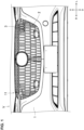
- FIG. 1 schematically shows main components of a front portion of the vehicle V, and illustration of other members, such as a bonnet and a shroud panel, is omitted here.
- a bumper face 1 which extends in the vehicle width direction is provided at the front portion of the vehicle V.
- the bumper face '' 1 may be formed in a gently-curved shape such that a center, in the vehicle width direction, thereof protrudes forward, and covers over a front-end part of the vehicle.
- the bumper face 1 may have a grill opening 11 at a central portion, in the vehicle width direction, thereof.
- the grill opening 11 is a traveling-air introduction hole, where a grill member 2 is provided.
- the grill member 2 may be formed in a grid shape in an elevational view, in a gently-curved shape such that a center, in the vehicle vertical direction, thereof protrudes forward slightly in a side view, and in a gently-curved shape such that a center, in the vehicle with direction, thereof protrudes forward in a plan view.
- a decorative member 3 is attached to the grill member 2, particularly, an upper-left area of the grill member 2.
- the decorative member 3 can be attached to any area of the grill member 2.
- the decorative member 3 is attached to the grill member 2, and the grill member 2 can be referred to as an "attached member” and the decorative member 3 can be referred to as an "attaching member.”
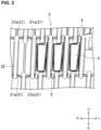
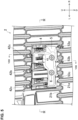
- FIG. 2 is an elevational view of an enlarged area where the decorative member 3 is attached to the grill member 2.
- the decorative member 3 may have a design surface at its front face in the elevational view.
- the grill member 2 comprises plural lateral portions 21 and one or plural vertical portions 22 which may be integrated, and is of a grid shape in the elevational view.
- the lateral portion 21 includes a first lateral portion 21a and a second lateral portion 21b.
- the first lateral portion 21a may be formed in a bar shape extending substantially in the vehicle width direction such that it is inclined slightly upward from its left side toward its right side.
- the second lateral portion 21b may also be formed in a bar shape extending substantially in the vehicle width direction such that it is inclined slightly upward from its right side toward its left side.
- the lateral portions 21 are separated from each other in the vehicle vertical direction.
- the lateral portion 21 corresponds to a first frame portion.
- the vertical portion 22 may extend in the vehicle vertical direction and may be of a rectangular shape having a larger thickness than the first lateral portion 21a and the second lateral portion 21b.
- the vertical portion 22 may be configured such that its upper-end portion is interposed between a left-side end portion of the first lateral portion 21a and a right-side end portion of the second lateral portion 21b, and that its lower-end portion is interposed between a right-side end portion of the first lateral portion 21a and a left-side end portion of the second lateral portion 21b.
- the vertical portion 22 corresponds to a second frame portion.
- the plural first lateral portions 21a may be parallel to each other, the plural second lateral portions 21b are parallel to each other, and the plural vertical portions 22 are parallel to each other.
- the decorative member 3 comprises a first member 4 and a second member 5.
- the first member 4 and the second member 5 engage with each other and they are attached to the grill member 2.
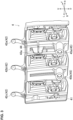
- FIG. 3 is a perspective view of the first member 4 before being attached to the grill member 2, when viewed from a rear-right side of the vehicle.
- the first member 4 may be a resin-made member, which comprises a body portion 41, one or plural first engaging portions (or one or plural first hook portions) 42, an engaging portion 43, a rib portion 44 which is provided at the engaging portion 43, and one or plural first insertion holes 45, which may be integrally formed with the body portion 41.
- the body portion 41 may extend in the vehicle width direction and/or in the vehicle vertical direction.
- a design surface may be formed at a front side of the body portion 41.
- the plural first engaging portions 42 may extend upward from an upper end of the body portion 41.
- the plural first engaging portions 42 are configured to be separated from each other e.g., in the vehicle width direction.
- each of the first engaging portions 42 may be bent rearward in a hook shape.
- the plural first engaging portions 42 may engage with the lateral portions 21 from a front-and-upper side.
- the plural first engaging portions 42 may include a right-side first engaging portion 42a which is arranged at the rightmost side R in the vehicle width direction, a left-side first engaging portion 42c which is arranged at the leftmost side L in the vehicle width direction, and a central first engaging portion 42b which is arranged between the right-side first engaging portion 42a and the left-side first engaging portion 42c in the vehicle width direction.
- the engaging portion 43 may projects rearward from the body portion 41 and extends in the vehicle longitudinal direction and in the vehicle vertical direction.
- the engaging portion 43 may be formed in a trapezoidal shape such that it expands in the vehicle vertical direction from its tip toward its base end in a side view.
- An inclined portion 43a which is inclined, particularly inclined upward from a lower side, is formed e.g., at an upper-side portion of the engaging portion 43 in an area extending from a tip of the engaging portion 43 to a base end of the engaging portion 43. Further, the engaging portion 43 may be positioned between the right-side first engaging portion 42a and the central first engaging portion 42b in the vehicle width direction.
- the rib portion 44 may be formed along both-side faces, in the vehicle width direction, of the engaging portion 43.
- the rib 44 may protrude rearward from the body portion 41 and extends in the vehicle longitudinal direction and in the vehicle width direction.
- the rib portion 44 may be formed in the trapezoidal shape such that it expands in the vehicle vertical direction toward the body portion 41 in a plan view.
- the rib portion 44 may increase the rigidity of the engaging portion 43.
- a rear end of the rib portion 44 may be positioned on a forward side of a rear end of the engaging portion 43.
- the plural first insertion holes 45 may be configured such that fastening members 6, described later, are inserted into these holes 45.
- the first insertion hole 45 may be formed in a hollow-cylindrical shape which protrudes rearward from the body portion 41.
- a first insertion hole 45a, one of the first insertion holes 45, may be formed just below the engaging portion 43.
- Another first insertion hole 45b may be formed at a position which is located at the same level as the first insertion hole 45a and between the left-side first engaging portion 42c and the central first engaging portion 42b in the vehicle width direction.
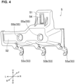
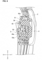
- FIG. 4 is a perspective view of the second member 5 before being attached to the grill member 2, when viewed from the rear-right side.
- the second member 5 may be a resin-made member, which comprises an upper-side body portion 51 and a lower-side body portion 52 which are formed integrally, plural second engaging portions 53, an engaged portion 54, plural second insertion holes 55.
- the upper-side body portion 51 may extend in the vehicle width direction and in the vehicle vertical direction. An upper end of the upper-side body portion 51 may be configured to be bent forward.
- the lower-side body portion 52 may protrude rearward in the side view and open at its front side.
- the lower-side body portion 52 may be formed integrally with the upper-side body portion 51 such that it extends downward from a lower end of the upper-side body portion 51.
- the plural second engaging portions 53 may extend forward from a lower end of the lower-side body portion 52.
- the plural second engaging portions 53 may be configured to be separated from each other.
- a front-end portion of each of the second engaging portions 53 may be bent rearward in a hook shape.
- the plural second engaging portions 53 engage with the lateral portions 21 which are located below the first engaging portions 42 particularly from a front-and-lower side.
- the plural second engaging portions 53 may include a right-side second engaging portion 53a which is arranged at the rightmost side, a left-side second engaging portion 53c which is arranged at the leftmost side, and a central second engaging portion 53b which is arranged between the right-side second engaging portion 53a and the left-side second engaging portion 53c in the vehicle width direction.
- the engaged portion 54 may be a rectangular-shaped hole which is formed at the upper-side body portion 51 and extends in the vehicle vertical direction in an elongated shape.
- a pair of triangular-shaped ribs, in the side view, may be formed at both sides, in the vehicle width direction, of the engaged portion 54. These ribs may serve as a reinforcing member to connect the upper-side body portion 51 and an upper face of a protrusion portion of the lower-side body portion 52.
- the plural second insertion holes 55 may be configured such that the fastening members 6, described later, are inserted thereinto.
- the second insertion hole 55 may be a circular hole which is formed at a face of the protrusion portion of the lower-side body portion 52 which extends in the vehicle vertical direction and in the vehicle width direction.
- a second insertion hole 55a, one of the plural second insertion holes 55, may be formed just below the engaging portion 43.
- Another second insertion hole 55b, the other one of the plural second insertion holes 55 may be formed at a position which is located at the same level as the second insertion hole 55a and between the left-side second engaging portion 53c and the central second engaging portion 53b in the vehicle width direction.
- FIG. 5 is a view of an area shown in FIG. 2 , when viewed from a rear side of the grill member 2.
- the decorative member 3 comprises the first member 4 and the second member 5 which is positioned behind the first member 4.
- a positional relationship of the first member 4 and the second member 5, when viewed from the rear side of the grill member 2, in a case where the first and second members 4, 5 are attached to the grill member 2 is as follows.
- the right-side second engaging portion 53a may be positioned on the right side of the right-side first engaging portion 42a
- the central second engaging portion 53b may be positioned between the right-side first engaging portion 42a and the central first engaging portion 42b
- the left-side second engaging portion 53c may be positioned between the central first engaging portion 42b and the left-side first engaging portion 42c.
- the engaged portion 54 may overlap the engaging portion 43 in the vehicle longitudinal direction so that the engaging portion 43 can be inserted into the engaged portion 54.
- the second insertion hole 55a may overlap the first insertion hole 45a in the vehicle longitudinal direction
- the second insertion hole 55b may overlap the first insertion hole 45b in the vehicle longitudinal direction.
- the plural fastening members 6 may be inserted into the plural second insertion holes 55 and the plural first insertion holes 45, respectively, so that the first and second members 4, 5 are fastened together.
- the first member 4 is attached to the grill member 2.
- the hook-shaped portions of their upper-end portions come to engage with the first lateral portions 21a from the front side and the upper side of the grill member 2.
- the first engaging portions 42 contact upper faces of the first lateral portions 21a at the hook-shaped portions of their upper-end portions, thereby restricting the first member 4 from moving downward.
- the second member 5 is attached from the rear side of the grill member 2.
- the hook-shaped portions of their upper-end portions come to engage with the first lateral portions 21a from the front side and the lower side of the grill member 2.
- the second engaging portions 53 contact lower faces of the first lateral portions 21a at the hook-shaped portions of their upper-end portions, thereby restricting the second member 5 from moving upward.
- the engaging portion 43 engages with the engaged portion 54.
- the inclined portion 43a which is inclined upward from the lower side is formed at the upper-side portion of the engaging portion 43 in the area extending from the tip of the engaging portion 43 to the base end of the engaging portion 43.
- the upper portion of the second member 5 may be moved from a state where the upper portion of the second member 5 is inclined rearward relative to the first member 4 so that the engaging portion 43 is inserted into the engaged portion 54. Consequently, the engaging portion 43 engages with the engaged portion 54.
- the inclined portion 43a and an upper side of the rectangular-shaped hole of the engaged portion 54 may contact each other. Further, a rear-end portion of the rib portion 44 may contact the second member 5.
- the plural fastening members 6 may be inserted into the plural first insertion holes 45 and the plural second insertion holes 55 which overlap each other, so that the first member 4 and the second member 5 are fixedly fastened.
- the inclined portion 43a of the engaging portion 43 and the upper side of the rectangular-shaped hole of the engaged portion 54 may contact each other.
- a force of the second member 5 for drawing down the first member 4 may act on a contact portion where the inclined portion 43a and the engaged portion 54.
- first engaging portion 42 of the first member 4 engages from the upper side. That is, the first member 4 is restricted from moving downward by the first engaging portion 42.
- the upward moving of the first member 4 is restricted by receiving the downward force at the contact portion with the engaged portion 54. Meanwhile, the downward moving of the first member 4 is restricted by the first engaging portion 42 as well. Accordingly, the first member 4 is restricted from moving in the vertical direction.
- a force of the first member 4 for drawing up the second member 5 may act on the contact portion where the inclined portion 43a and the engaged portion 54 contact each other. This force is an upward-directed force. Further, the second engaging portion 53 engages with the second member 5 from the lower side. That is, the second member 5 is restricted from moving upward by the second engaging portion 53.
- the downward moving of the second member 5 is restricted by receiving the upward force at the contact portion with the inclined portion 43a. Meanwhile, the upward moving of the second member 5 is restricted by the second engaging portion 53 as well. Accordingly, the second member 5 is restricted from moving in the vertical direction.
- the engaging portion 43 may engage with the engaged portion 54 by gradually moving an upper portion of the second member 5 vehicle forward from a state in which the upper portion of the second member 5 is inclined rearward relative to the first member 4 in the attaching.
- an inclination angle of the inclined portion 43a may be set at an appropriate angle enough to prevent the engaged portion 54 from sliding in a state where the inclined portion 43a and the engaged portion 54 contact each other.
- the inclination angle of the inclined portion 43a may be set such that a static frictional force generated between the engaging portion 43 and the engaged portion 54 is larger than a rearward-directed force acting on the engaged portion 54 along the inclined portion 43a in the state where the inclined portion 43a and the engaged portion 54 contact each other.
- the engaging directions are not limited to these and any direction, i.e., not only the vertical direction but the lateral direction and the longitudinal direction, is applicable as long as the both engaging directions of these portions 42, 53 are opposite to each other.
- the attached member of the above-described embodiment is the grill member 2 which comprises the plural first-and-second lateral portions 21a, 21b and the plural vertical portions 22 which are all integrated
- the present invention is also applicable to an attached member which comprises either one of the lateral potions and the vertical portions.
- the inclined portion 43a is provided at a whole part of the upper-side portion of the engaging portion 43 in the above-described embodiment, it may be provided partially at a lateral part of the upper-side portion of the engaging portion 43 and the inclined portion may be provided at a front side and a rear side of this lateral part, respectively.
- the attached member is not limited to the grill member of the vehicle and any other members than that provided at the vehicle, such as a fence for an architecture member or various types of grid members for furniture or home electronics, are applicable.
- the attaching member is not limited to the decorative member but any kinds of members, such as emblem members or sensors, can be used as well.
- the members according to the present invention can be used in a case where various types of attaching members are attached to the engaged members.
Landscapes
- Engineering & Computer Science (AREA)
- Mechanical Engineering (AREA)
- Vehicle Interior And Exterior Ornaments, Soundproofing, And Insulation (AREA)
- Connection Of Plates (AREA)
Abstract
Description
- The present invention relates to an attaching member, a combination of the attaching member and an attached member, and a vehicle.
-
Japanese Patent Laid-Open Publication No. 2019-217934 - As disclosed in the above-described patent document, it is general to provide a fastening structure at an attached member in a case where an attaching member, such as the emblem, is attached to the attached member, such as the grill.
- However, when the above-described fastening structure disclosed in the patent document is not provided previously, any other structure for attaching the attaching member may be necessary additionally. Herein, since some backlash (looseness) may occur due to its inappropriate attaching manner, some proper attaching structure for stabilizing attachment without backlash may become necessary.
- An object of the present invention is to provide an attaching member which can be properly attached to an attached member in a stable state with no backlash (looseness), without providing any particular fastening structure at the attached member.
- The present invention is defined in independent claims. Preferred embodiments are defined in dependent claims. Particularly, in e.g., an electric automobile, an attaching member to be attached to an attached member is provided. Further particularly, the attached member comprises a pair of first frame portions which extend in a first direction, respectively, and are separated from each other in a second direction crossing the first direction, the attaching member comprises a first member including a first engaging portion (or a first hook portion) which engages with the first frame portions from one side of the second direction and a second member including a second engaging portion (or a second hook portion) which engages with a portion of the first frame portion which is positioned on the other side, in the second direction, of the first engaging portion from the other side of the second direction, the first member includes an engaging portion which extends in a third direction crossing both directions crossing the first direction and the second direction and engages with the second member, the second member includes an engaged portion which the engaging portion of the first member engages with, the engaging portion includes an inclined portion which is positioned on the one side of the second direction and extends obliquely from a tip of the engaging portion toward a base portion of the engaging portion and from the other side of the second direction to the one side of the second direction, and a portion of the engaging portion which is positioned on the one side of the second direction engages with the engaged portion of the second member.
- According to the present invention, since the inclined portion extending obliquely from the tip of the engaging portion toward the base portion of the engaging portion and from the other side of the second direction to the one side of the second direction is provided, the engaged portion can be engaged by the engaging portion by gradually moving the second member toward the base portion of the engaging portion of the third direction from a state where the second member is inclined toward the tip of the engaging portion of the third direction relative to the first member when being attached. Herein, the first member receives a force which is applied from the engaged portion to the other side of the second direction at the engaging portion. Since the first engaging portion engages with the first frame portion from the one side of the second direction, when the force applied to the other side of the second direction is inputted to the first member, the moving to the one side of the second direction is restricted at the first engaging member. Meanwhile, the second member receives a force which is applied to the one side of the second direction from the engaging portion at the engaged portion. Since the second engaging portion engages with the first frame portion from the other side of the second direction, when the force applied to the one side of the second direction is inputted to the second member, the moving to the other side of the second direction is restricted at the second engaging portion. This cooperation of the first and second members enables attaching of the first and second members to the engaged member, without providing any particular fastening structure at the engaged member. Further, the attaching member can be suppressed from having some backlash (looseness) in the second direction, thereby ensuring the attaching in the stable state.
- In an embodiment of the present invention, the first engaging portion and the second engaging portion of the attaching member may be to engage with the first frame portion of the attached member from the same side of the third direction.
- According to this embodiment, both of the first and second members can be attached from the same side of the third direction at the attached member, so that workability of the attaching can be improved.
- In another embodiment of the present invention, the engaging portion of the first member may be provided with a rib portion which extends in the first direction and in the third direction and contacts the engaged portion of the second member.
- According to this embodiment, the rigidity of the engaging portion can be increased, and also positioning of the engaging portion and the engaged portion can be facilitated in the engaging. Thereby, moving of the first and second engaging portions in the second direction can be restricted and also an appropriate force which may not deform the first and second engaging portions can be inputted.
- In another embodiment of the present invention, each of the first engaging portion and the second engaging portion of the attaching member may be constituted by plural portions. In other words, the first member may include a plurality of first engaging portions. The second member may include a plurality of second engaging portions.
- According to this embodiment, the moving of the first and second members can be restricted respectively at different points, so that backlash (looseness) of the members in the second direction can be suppressed securely.
- In another embodiment of the present invention, the attaching member may further comprise a fastening member to fasten the first member and the second member.
- According to this embodiment, the first and second members are fixed so securely that the backlash (looseness) of these members in the second direction can be suppressed more securely.
- In another embodiment of the present invention, the attached member may be a grill for a vehicle which comprises the first frame portion and a second frame portion which extends in the second direction.
- According to this embodiment, the first and second members can be attached to the grill for the vehicle, without providing any particular fastening structure at the grill for the vehicle, and the backlash (looseness) of the members in the second direction can be suppressed.
- In another embodiment of the present invention, the first engaging portion and the second engaging portion of the attaching member may be a decorative member to be attached to the vehicle.
- According to this embodiment, the decorative member can be attached to the grill for the vehicle, without providing any particular fastening structure at the grill for the vehicle, and the backlash (looseness) of the decorative member in the second direction can be suppressed.
- The present invention will become apparent from the following description which refers to the accompanying drawings.
-
-
FIG. 1 is a front view or an elevational view of a front structure of a vehicle according to an embodiment. -
FIG. 2 is a front view or an elevational view of a decorative member which is attached to a grill for the vehicle in the front structure of the vehicle according to the embodiment. -
FIG. 3 is a perspective view of a first member before attaching. -
FIG. 4 is a perspective view of a second member before the attaching. -
FIG. 5 is a back-face view showing the decorative member attached to the grill for the vehicle in the front structure of the vehicle according to the embodiment. -
FIG. 6 is a sectional view showing a positional relationship of an engaging portion and an engaged portion. -
FIG. 7 is a sectional view around the engaging portion. -
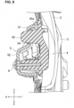
FIG. 8 is a sectional view taken along line VIII-VIII ofFIG. 5 . -
FIG. 9 is a sectional view taken along line IX-IX ofFIG. 5 . - Hereafter, an embodiment of the present invention will be described specifically referring to the drawings. Herein, the embodiment described below is just an example of the present invention, and therefore it does not to intend to restrict any application or use of the present invention.
- The following description and figures are appropriately omitted and simplified for clarification. In the figures, the same reference characters are used for the same elements, and some duplications are omitted as needed. In the drawings, directions mean the ones on the figures if not particularly referred to, and a vehicle longitudinal direction is shown by arrows F, B, a lateral direction, in a width direction, of a vehicle is shown by arrows L, R, and a vehicle vertical direction is shown by arrows U, D.
- Herein, in the embodiment, the parallel, horizontal, and vertical directions or the like have some tolerance enough not to hinder the effects of the present invention. The vehicle longitudinal direction corresponds to a third direction, the vehicle width direction corresponds to a first direction, and the vehicle vertical direction corresponds to a second direction.
- A front structure of a vehicle (e.g., an electric vehicle or an electric automobile) V will be described referring to
FIG. 1. FIG. 1 schematically shows main components of a front portion of the vehicle V, and illustration of other members, such as a bonnet and a shroud panel, is omitted here. Abumper face 1 which extends in the vehicle width direction is provided at the front portion of the vehicle V. - The bumper face ''1 may be formed in a gently-curved shape such that a center, in the vehicle width direction, thereof protrudes forward, and covers over a front-end part of the vehicle. The
bumper face 1 may have a grill opening 11 at a central portion, in the vehicle width direction, thereof. The grill opening 11 is a traveling-air introduction hole, where agrill member 2 is provided. - The
grill member 2 may be formed in a grid shape in an elevational view, in a gently-curved shape such that a center, in the vehicle vertical direction, thereof protrudes forward slightly in a side view, and in a gently-curved shape such that a center, in the vehicle with direction, thereof protrudes forward in a plan view. Adecorative member 3 is attached to thegrill member 2, particularly, an upper-left area of thegrill member 2. Herein, thedecorative member 3 can be attached to any area of thegrill member 2. Thedecorative member 3 is attached to thegrill member 2, and thegrill member 2 can be referred to as an "attached member" and thedecorative member 3 can be referred to as an "attaching member." - A structural example of the
grill member 2 and an attachment example in which thedecorative member 3 is attached to thegrill member 2 will be described referring toFIG. 2. FIG. 2 is an elevational view of an enlarged area where thedecorative member 3 is attached to thegrill member 2. Thedecorative member 3 may have a design surface at its front face in the elevational view. - The
grill member 2 comprises plurallateral portions 21 and one or pluralvertical portions 22 which may be integrated, and is of a grid shape in the elevational view. Thelateral portion 21 includes a firstlateral portion 21a and a secondlateral portion 21b. - The first
lateral portion 21a may be formed in a bar shape extending substantially in the vehicle width direction such that it is inclined slightly upward from its left side toward its right side. The secondlateral portion 21b may also be formed in a bar shape extending substantially in the vehicle width direction such that it is inclined slightly upward from its right side toward its left side. - The thickness of these
portions grill member 2 may be configured such that the firstlateral portions 21a and the secondlateral portions 21b are formed mutually in the vehicle width direction. - The lateral portions 21 (21a, 21b) are separated from each other in the vehicle vertical direction. The
lateral portion 21 corresponds to a first frame portion. - The
vertical portion 22 may extend in the vehicle vertical direction and may be of a rectangular shape having a larger thickness than the firstlateral portion 21a and the secondlateral portion 21b. Thevertical portion 22 may be configured such that its upper-end portion is interposed between a left-side end portion of the firstlateral portion 21a and a right-side end portion of the secondlateral portion 21b, and that its lower-end portion is interposed between a right-side end portion of the firstlateral portion 21a and a left-side end portion of the secondlateral portion 21b. Thevertical portion 22 corresponds to a second frame portion. - The plural first
lateral portions 21a may be parallel to each other, the plural secondlateral portions 21b are parallel to each other, and the pluralvertical portions 22 are parallel to each other. - The
decorative member 3 comprises afirst member 4 and asecond member 5. Thefirst member 4 and thesecond member 5 engage with each other and they are attached to thegrill member 2. - Next, a structural example of the
decorative member 3 will be described referring toFIGS. 3 - 5 . - A structural example of the
first member 4 will be described referring toFIG. 3. FIG. 3 is a perspective view of thefirst member 4 before being attached to thegrill member 2, when viewed from a rear-right side of the vehicle. Thefirst member 4 may be a resin-made member, which comprises abody portion 41, one or plural first engaging portions (or one or plural first hook portions) 42, an engagingportion 43, arib portion 44 which is provided at the engagingportion 43, and one or plural first insertion holes 45, which may be integrally formed with thebody portion 41. - The
body portion 41 may extend in the vehicle width direction and/or in the vehicle vertical direction. A design surface may be formed at a front side of thebody portion 41. - The plural first
engaging portions 42 may extend upward from an upper end of thebody portion 41. The plural firstengaging portions 42 are configured to be separated from each other e.g., in the vehicle width direction. - An upper-end portion of each of the first engaging
portions 42 may be bent rearward in a hook shape. The plural firstengaging portions 42 may engage with thelateral portions 21 from a front-and-upper side. - The plural first
engaging portions 42 may include a right-side first engagingportion 42a which is arranged at the rightmost side R in the vehicle width direction, a left-side first engagingportion 42c which is arranged at the leftmost side L in the vehicle width direction, and a central firstengaging portion 42b which is arranged between the right-side first engagingportion 42a and the left-side first engagingportion 42c in the vehicle width direction. - The engaging
portion 43 may projects rearward from thebody portion 41 and extends in the vehicle longitudinal direction and in the vehicle vertical direction. The engagingportion 43 may be formed in a trapezoidal shape such that it expands in the vehicle vertical direction from its tip toward its base end in a side view. - An
inclined portion 43a which is inclined, particularly inclined upward from a lower side, is formed e.g., at an upper-side portion of the engagingportion 43 in an area extending from a tip of the engagingportion 43 to a base end of the engagingportion 43. Further, the engagingportion 43 may be positioned between the right-side first engagingportion 42a and the central firstengaging portion 42b in the vehicle width direction. - The
rib portion 44 may be formed along both-side faces, in the vehicle width direction, of the engagingportion 43. Therib 44 may protrude rearward from thebody portion 41 and extends in the vehicle longitudinal direction and in the vehicle width direction. Therib portion 44 may be formed in the trapezoidal shape such that it expands in the vehicle vertical direction toward thebody portion 41 in a plan view. Therib portion 44 may increase the rigidity of the engagingportion 43. Herein, a rear end of therib portion 44 may be positioned on a forward side of a rear end of the engagingportion 43. - The plural first insertion holes 45 may be configured such that
fastening members 6, described later, are inserted into theseholes 45. Thefirst insertion hole 45 may be formed in a hollow-cylindrical shape which protrudes rearward from thebody portion 41. Afirst insertion hole 45a, one of the first insertion holes 45, may be formed just below the engagingportion 43. Anotherfirst insertion hole 45b may be formed at a position which is located at the same level as thefirst insertion hole 45a and between the left-side first engagingportion 42c and the central firstengaging portion 42b in the vehicle width direction. - Next, a structural example of the
second member 5 will be described referring toFIG. 4. FIG. 4 is a perspective view of thesecond member 5 before being attached to thegrill member 2, when viewed from the rear-right side. Thesecond member 5 may be a resin-made member, which comprises an upper-side body portion 51 and a lower-side body portion 52 which are formed integrally, plural secondengaging portions 53, an engagedportion 54, plural second insertion holes 55. - The upper-
side body portion 51 may extend in the vehicle width direction and in the vehicle vertical direction. An upper end of the upper-side body portion 51 may be configured to be bent forward. The lower-side body portion 52 may protrude rearward in the side view and open at its front side. The lower-side body portion 52 may be formed integrally with the upper-side body portion 51 such that it extends downward from a lower end of the upper-side body portion 51. - The plural second
engaging portions 53 may extend forward from a lower end of the lower-side body portion 52. The plural secondengaging portions 53 may be configured to be separated from each other. A front-end portion of each of the secondengaging portions 53 may be bent rearward in a hook shape. The plural secondengaging portions 53 engage with thelateral portions 21 which are located below the first engagingportions 42 particularly from a front-and-lower side. - The plural second
engaging portions 53 may include a right-side second engagingportion 53a which is arranged at the rightmost side, a left-side second engagingportion 53c which is arranged at the leftmost side, and a central secondengaging portion 53b which is arranged between the right-side second engagingportion 53a and the left-side second engagingportion 53c in the vehicle width direction. - The engaged
portion 54 may be a rectangular-shaped hole which is formed at the upper-side body portion 51 and extends in the vehicle vertical direction in an elongated shape. A pair of triangular-shaped ribs, in the side view, may be formed at both sides, in the vehicle width direction, of the engagedportion 54. These ribs may serve as a reinforcing member to connect the upper-side body portion 51 and an upper face of a protrusion portion of the lower-side body portion 52. - The plural second insertion holes 55 may be configured such that the
fastening members 6, described later, are inserted thereinto. Thesecond insertion hole 55 may be a circular hole which is formed at a face of the protrusion portion of the lower-side body portion 52 which extends in the vehicle vertical direction and in the vehicle width direction. Asecond insertion hole 55a, one of the plural second insertion holes 55, may be formed just below the engagingportion 43. Anothersecond insertion hole 55b, the other one of the plural second insertion holes 55, may be formed at a position which is located at the same level as thesecond insertion hole 55a and between the left-side second engagingportion 53c and the central secondengaging portion 53b in the vehicle width direction. - Next, a relationship of the
first member 4 and thesecond member 5 will be described referring toFIG. 5. FIG. 5 is a view of an area shown inFIG. 2 , when viewed from a rear side of thegrill member 2. Thedecorative member 3 comprises thefirst member 4 and thesecond member 5 which is positioned behind thefirst member 4. - As shown in
FIG. 5 , a positional relationship of thefirst member 4 and thesecond member 5, when viewed from the rear side of thegrill member 2, in a case where the first andsecond members grill member 2 is as follows. The right-side second engagingportion 53a may be positioned on the right side of the right-side first engagingportion 42a, the central secondengaging portion 53b may be positioned between the right-side first engagingportion 42a and the central firstengaging portion 42b, and the left-side second engagingportion 53c may be positioned between the central firstengaging portion 42b and the left-side first engagingportion 42c. - The engaged
portion 54 may overlap the engagingportion 43 in the vehicle longitudinal direction so that the engagingportion 43 can be inserted into the engagedportion 54. Thesecond insertion hole 55a may overlap thefirst insertion hole 45a in the vehicle longitudinal direction, and thesecond insertion hole 55b may overlap thefirst insertion hole 45b in the vehicle longitudinal direction. As described later, theplural fastening members 6 may be inserted into the plural second insertion holes 55 and the plural first insertion holes 45, respectively, so that the first andsecond members - Next, an attaching manner in which the
decorative member 3 is attached to thegrill member 2 will be described referring toFIG. 6 . - First, the
first member 4 is attached to thegrill member 2. After the one or plural firstengaging portions 42 are inserted into gaps between the adjacentvertical portions lateral portions 21a from the front side and the upper side of thegrill member 2. Thereby, the first engagingportions 42 contact upper faces of the firstlateral portions 21a at the hook-shaped portions of their upper-end portions, thereby restricting thefirst member 4 from moving downward. - Then, the
second member 5 is attached from the rear side of thegrill member 2. After the one or plural secondengaging portions 53 are inserted into gaps between lower end of thefirst member 4 and thevertical portions 2, the hook-shaped portions of their upper-end portions come to engage with the firstlateral portions 21a from the front side and the lower side of thegrill member 2. Thereby, the secondengaging portions 53 contact lower faces of the firstlateral portions 21a at the hook-shaped portions of their upper-end portions, thereby restricting thesecond member 5 from moving upward. - Next, the engaging
portion 43 engages with the engagedportion 54. As described above, theinclined portion 43a which is inclined upward from the lower side is formed at the upper-side portion of the engagingportion 43 in the area extending from the tip of the engagingportion 43 to the base end of the engagingportion 43. Thereby, as shown inFIG. 6 , the upper portion of thesecond member 5 may be moved from a state where the upper portion of thesecond member 5 is inclined rearward relative to thefirst member 4 so that the engagingportion 43 is inserted into the engagedportion 54. Consequently, the engagingportion 43 engages with the engagedportion 54. - Herein, the
inclined portion 43a and an upper side of the rectangular-shaped hole of the engagedportion 54 may contact each other. Further, a rear-end portion of therib portion 44 may contact thesecond member 5. - Finally, the
plural fastening members 6 may be inserted into the plural first insertion holes 45 and the plural second insertion holes 55 which overlap each other, so that thefirst member 4 and thesecond member 5 are fixedly fastened. - The
decorative member 3 is attached to thegrill member 2 in the above-described manner. Further, the design surface of thefirst member 4 may be viewed through the gaps of the grid-shapedgrill member 2 in the elevational view. The upper-side body portion 51 and the lower-side body portion 52 of thesecond member 5 may be positioned on the vehicle rearward side of thebody portion 41 of thefirst member 4. - Next, a structure in which the
decorative member 3 is attached to thegrill member 2 will be described referring toFIGS. 7 - 9 . - As shown in
FIG. 7 , theinclined portion 43a of the engagingportion 43 and the upper side of the rectangular-shaped hole of the engagedportion 54 may contact each other. - A force of the
second member 5 for drawing down thefirst member 4 may act on a contact portion where theinclined portion 43a and the engagedportion 54. - Further, the first engaging
portion 42 of thefirst member 4 engages from the upper side. That is, thefirst member 4 is restricted from moving downward by the first engagingportion 42. - That is, the upward moving of the
first member 4 is restricted by receiving the downward force at the contact portion with the engagedportion 54. Meanwhile, the downward moving of thefirst member 4 is restricted by the first engagingportion 42 as well. Accordingly, thefirst member 4 is restricted from moving in the vertical direction. - Meanwhile, a force of the
first member 4 for drawing up thesecond member 5 may act on the contact portion where theinclined portion 43a and the engagedportion 54 contact each other. This force is an upward-directed force. Further, the second engagingportion 53 engages with thesecond member 5 from the lower side. That is, thesecond member 5 is restricted from moving upward by the second engagingportion 53. - That is, the downward moving of the
second member 5 is restricted by receiving the upward force at the contact portion with theinclined portion 43a. Meanwhile, the upward moving of thesecond member 5 is restricted by the second engagingportion 53 as well. Accordingly, thesecond member 5 is restricted from moving in the vertical direction. - Further, since the
inclined portion 43a is provided, the engagingportion 43 may engage with the engagedportion 54 by gradually moving an upper portion of thesecond member 5 vehicle forward from a state in which the upper portion of thesecond member 5 is inclined rearward relative to thefirst member 4 in the attaching. - Herein, an inclination angle of the
inclined portion 43a may be set at an appropriate angle enough to prevent the engagedportion 54 from sliding in a state where theinclined portion 43a and the engagedportion 54 contact each other. Particularly, the inclination angle of theinclined portion 43a may be set such that a static frictional force generated between the engagingportion 43 and the engagedportion 54 is larger than a rearward-directed force acting on the engagedportion 54 along theinclined portion 43a in the state where theinclined portion 43a and the engagedportion 54 contact each other. - As described above, the
first member 4 and thesecond member 5 engage with each other by means of the engagingportion 43 and the engagedportion 54, and their upward-and-downward moving, i.e., their moving in the vehicle vertical direction, are restricted. Accordingly, the attaching of thedecorative member 3 comprising thefirst member 4 and thesecond member 5 can be attained without proving any particular structure at thegrill member 2, and the backlash (looseness) of thedecorative member 3 in the vertical direction can be suppressed. - Further, both the
first member 4 and thesecond member 5 may be attached to the back face of thegrill member 2, i.e., to a vehicle-rearward-side face of thegrill member 2. Particularly, since the first engagingportion 42 and the second engagingportion 53 engage with thelateral portions 21 from the front side, both thefirst member 4 and thesecond member 5 can be attached to thegrill member 2 from the same side in their attaching, thereby improving the workability in the attaching. -
FIG. 8 is a sectional view taken along line VIII-VIII ofFIG. 5 . At the engagingportion 43 may be provided therib portion 44 which extends in the vehicle vertical direction and in the vehicle width direction along the respective faces of its vehicle width direction. Thereby, the rigidity of the engagingportion 43 may be increased. - Further, since a rear end of the
rib portion 44 may contact the second member, positioning of the engagingportion 43 and the engagedportion 54 when they engage with each other may be facilitated. Accordingly, an appropriate force enough to restrict their moving in the vertical direction but to prevent any improper deformation of those can be inputted to the first engagingportion 42 and the second engagingportion 53. - Further, each of the first engaging
portion 42 and the second engagingportion 53 may be constituted by plural portions. In other words, plural firstengaging portions 42 and plural secondengaging portions 53 may be provided. Accordingly, the moving of thesemembers decorative member 3. - Moreover, the
decorative member 3 may comprise theplural fastening members 6 to fasten thefirst member 4 and thesecond member 5. Accordingly, thefirst member 4 and thesecond member 5 may be so securely fixed that their vertical backlash (looseness) can be suppressed more securely. - The present invention is not limited to the above-described embodiment, but any modifications is applicable.
- While the above-described embodiment is configured such that the first engaging
portion 42 engages from the upper side and the second engagingportion 53 engages from the lower side, the engaging directions are not limited to these and any direction, i.e., not only the vertical direction but the lateral direction and the longitudinal direction, is applicable as long as the both engaging directions of theseportions - Further, while the attached member of the above-described embodiment is the
grill member 2 which comprises the plural first-and-second lateral portions vertical portions 22 which are all integrated, the present invention is also applicable to an attached member which comprises either one of the lateral potions and the vertical portions. - Moreover, while the
inclined portion 43a is provided at a whole part of the upper-side portion of the engagingportion 43 in the above-described embodiment, it may be provided partially at a lateral part of the upper-side portion of the engagingportion 43 and the inclined portion may be provided at a front side and a rear side of this lateral part, respectively. - Additionally, while the present invention is applied to the case where the decorative member is attached to the grill member in the above-described embodiment, the attached member is not limited to the grill member of the vehicle and any other members than that provided at the vehicle, such as a fence for an architecture member or various types of grid members for furniture or home electronics, are applicable. The attaching member is not limited to the decorative member but any kinds of members, such as emblem members or sensors, can be used as well.
- The members according to the present invention can be used in a case where various types of attaching members are attached to the engaged members.
Claims (13)
- An attaching member (3) to be attached to an attached member (2), wherein the attached member (2) comprises a pair of first frame portions (21) which are configured to extend in a first direction, respectively, and are separated from each other in a second direction crossing the first direction, the attaching member (3) comprising:a first member (4) including a first engaging portion (42) or a plurality of first engaging portions (42), wherein the first engaging portion (42) is configured to engage with the first frame portions (21) from one side of the second direction; anda second member (5) including a second engaging portion (53) or a plurality of second engaging portions (53), wherein the second engaging portion (53) is configured to engage with a portion of the first frame portion (21) which is positioned on the other side, in the second direction, of the first engaging portion (42) from the other side of the second direction,whereinthe first member (4) includes an engaging portion (43) which is configured to extend in a third direction crossing the first direction and the second direction and is configured to engage with the second member (5),the second member (5) includes an engaged portion (54) which the engaging portion (43) of the first member (4) is configured to engage with,the engaging portion (43) includes an inclined portion (43a) which is positioned on the one side of the second direction and is configured to extend obliquely from a tip of the engaging portion (43) toward a base portion of the engaging portion (43) and from the other side of the second direction to the one side of the second direction, anda portion of the engaging portion (43) which is positioned on the one side of the second direction is configured to engage with the engaged portion (54) of the second member (5).
- The attaching member (3) of claim 1, wherein the first engaging portion (42) and the second engaging portion (53) of the attaching member (3) are configured to engage with the first frame portion (21) of the attached member (2) from the same side of the third direction.
- The attaching member (3) of claim 1 or 2, wherein the engaging portion (43) of the first member (4) is provided with a rib portion (44), and
the rib portion (44) is configured to extend in the first direction and in the third direction and is configured to contact the engaged portion (54) of the second member (5). - The attaching member (3) of any one of the preceding claims, whereinthe first member (4) includes the plurality of first engaging portions (42), andthe second member (5) includes the plurality of second engaging portions (53).
- The attaching member (3) of any one of the preceding claims, further comprising a fastening member (6) configured to fasten the first member (4) and the second member (5).
- The attaching member (3) of any one of the preceding claims, whereinthe attached member (2) is a grill for a vehicle (V), andthe grill comprises the first frame portion (21) and a second frame portion (22) which extends in the second direction.
- The attaching member (3) of any one of the preceding claims, wherein the first engaging portion (42) and the second engaging portion (53) of the attaching member (3) are a decorative member configured to be attached to a vehicle (V).
- The attaching member (3) of any one of the preceding claims, wherein an upper-end portion of the first engaging portion (42) is of a hook shape which is configured to bend from one side of the third direction toward the other side of the third direction.
- The attaching member (3) of any one of the preceding claims, wherein a front-end portion of the second engaging portion (53) is of a hook shape which bends from one side of the third direction toward the other of the third direction.
- The attaching member (3) of any one of the preceding claims, wherein the first member (4) of the attaching member (3) is a resin-made member.
- The attaching member (3) of any one of the preceding claims, wherein the second member (5) of the attaching member (3) is a resin-made member.
- A combination of the attaching member (3) of any one of the preceding claims and an attached member (2), wherein the attached member (2) comprises a pair of first frame portions (21) which are configured to extend in a first direction, respectively, and are separated from each other in a second direction crossing the first direction.
- A vehicle (V) comprising the combination of claim 12.
Applications Claiming Priority (1)
| Application Number | Priority Date | Filing Date | Title |
|---|---|---|---|
| JP2023178629A JP2025068690A (en) | 2023-10-17 | 2023-10-17 | Attaching member |
Publications (2)
| Publication Number | Publication Date |
|---|---|
| EP4541663A1 true EP4541663A1 (en) | 2025-04-23 |
| EP4541663B1 EP4541663B1 (en) | 2025-10-08 |
Family
ID=92973473
Family Applications (1)
| Application Number | Title | Priority Date | Filing Date |
|---|---|---|---|
| EP24204209.1A Active EP4541663B1 (en) | 2023-10-17 | 2024-10-02 | Attaching member, combination of attaching member and attached member, and vehicle |
Country Status (4)
| Country | Link |
|---|---|
| US (1) | US20250121788A1 (en) |
| EP (1) | EP4541663B1 (en) |
| JP (1) | JP2025068690A (en) |
| CN (1) | CN119840521A (en) |
Families Citing this family (7)
| Publication number | Priority date | Publication date | Assignee | Title |
|---|---|---|---|---|
| US20230202415A1 (en) * | 2020-06-05 | 2023-06-29 | Honda Motor Co., Ltd. | Vehicle body front structure |
| US12589703B2 (en) * | 2023-03-13 | 2026-03-31 | Honda Motor Co., Ltd. | Vehicle grill mounting structure for float-mounting a vehicle element |
| TWD239118S (en) * | 2024-02-07 | 2025-07-01 | 美商福特環球科技有限公司 (美國) | Vehicle front upper grille |
| TWD239129S (en) * | 2024-02-07 | 2025-07-01 | 美商福特環球科技有限公司 (美國) | Vehicle front upper grille |
| USD1111952S1 (en) * | 2024-09-04 | 2026-02-10 | Audi Ag | Radiator grille for vehicle |
| USD1111951S1 (en) * | 2024-09-04 | 2026-02-10 | Audi Ag | Radiator grille for vehicle |
| USD1123740S1 (en) * | 2024-10-23 | 2026-04-28 | GM Global Technology Operations LLC | Vehicle grille |
Citations (3)
| Publication number | Priority date | Publication date | Assignee | Title |
|---|---|---|---|---|
| JP2019217934A (en) | 2018-06-21 | 2019-12-26 | スズキ株式会社 | Vehicle emblem assembly structure |
| CN114954330A (en) * | 2022-06-21 | 2022-08-30 | 重庆平伟汽车零部件有限公司 | A front bumper borderless grille structure |
| CN115352390A (en) * | 2022-09-20 | 2022-11-18 | 重庆长安汽车股份有限公司 | Air inlet grille assembly and assembling method thereof |
-
2023
- 2023-10-17 JP JP2023178629A patent/JP2025068690A/en active Pending
-
2024
- 2024-09-02 CN CN202411220610.2A patent/CN119840521A/en active Pending
- 2024-09-11 US US18/882,125 patent/US20250121788A1/en active Pending
- 2024-10-02 EP EP24204209.1A patent/EP4541663B1/en active Active
Patent Citations (3)
| Publication number | Priority date | Publication date | Assignee | Title |
|---|---|---|---|---|
| JP2019217934A (en) | 2018-06-21 | 2019-12-26 | スズキ株式会社 | Vehicle emblem assembly structure |
| CN114954330A (en) * | 2022-06-21 | 2022-08-30 | 重庆平伟汽车零部件有限公司 | A front bumper borderless grille structure |
| CN115352390A (en) * | 2022-09-20 | 2022-11-18 | 重庆长安汽车股份有限公司 | Air inlet grille assembly and assembling method thereof |
Also Published As
| Publication number | Publication date |
|---|---|
| CN119840521A (en) | 2025-04-18 |
| EP4541663B1 (en) | 2025-10-08 |
| JP2025068690A (en) | 2025-04-30 |
| US20250121788A1 (en) | 2025-04-17 |
Similar Documents
| Publication | Publication Date | Title |
|---|---|---|
| EP4541663A1 (en) | Attaching member, combination of attaching member and attached member, and vehicle | |
| US7651160B2 (en) | Vehicle seat | |
| EP3112220B1 (en) | Fixing structure and grille shutter unit | |
| CN104507742B (en) | Seat Sliders for Vehicles | |
| JPH1134771A (en) | Radiator grill | |
| JP2009035078A (en) | Floor console | |
| US20060113811A1 (en) | Support structure for mounting components on vehicle | |
| WO2019082881A1 (en) | Mounting structure of automotive parts | |
| JP2010023749A (en) | Vehicular instrument panel upper surface support structure | |
| JP6902218B2 (en) | Body front structure | |
| US7250573B2 (en) | Automotive cable holding system | |
| JP2001180522A (en) | Mounting structure of cowl top garnish | |
| JP2021160648A (en) | Vehicular seat slide device | |
| EP4253157A1 (en) | Cover assembly for fixing a cover member to a dashboard of a vehicle | |
| CN115366812B (en) | Interior trim part for passenger tool | |
| JP7846033B2 (en) | Seat cushion mounting structure and vehicle seat | |
| JP5186288B2 (en) | Wire harness retaining clip | |
| JP7737922B2 (en) | Vehicle seats | |
| JP5120236B2 (en) | Assembly structure of center lower panel in vehicle instrument panel | |
| US11318873B2 (en) | Headrest support structure and vehicle seat | |
| JP2008230336A (en) | Instrument panel mounting part structure | |
| CN108454529B (en) | Interior trim part for vehicle | |
| JP7067427B2 (en) | Vehicle structure | |
| JPH05338509A (en) | Grille mounting construction | |
| JP2006123739A (en) | Mounting parts fixing structure |
Legal Events
| Date | Code | Title | Description |
|---|---|---|---|
| PUAI | Public reference made under article 153(3) epc to a published international application that has entered the european phase |
Free format text: ORIGINAL CODE: 0009012 |
|
| STAA | Information on the status of an ep patent application or granted ep patent |
Free format text: STATUS: REQUEST FOR EXAMINATION WAS MADE |
|
| 17P | Request for examination filed |
Effective date: 20250306 |
|
| AK | Designated contracting states |
Kind code of ref document: A1 Designated state(s): AL AT BE BG CH CY CZ DE DK EE ES FI FR GB GR HR HU IE IS IT LI LT LU LV MC ME MK MT NL NO PL PT RO RS SE SI SK SM TR |
|
| GRAP | Despatch of communication of intention to grant a patent |
Free format text: ORIGINAL CODE: EPIDOSNIGR1 |
|
| STAA | Information on the status of an ep patent application or granted ep patent |
Free format text: STATUS: GRANT OF PATENT IS INTENDED |
|
| INTG | Intention to grant announced |
Effective date: 20250717 |
|
| GRAS | Grant fee paid |
Free format text: ORIGINAL CODE: EPIDOSNIGR3 |
|
| GRAA | (expected) grant |
Free format text: ORIGINAL CODE: 0009210 |
|
| STAA | Information on the status of an ep patent application or granted ep patent |
Free format text: STATUS: THE PATENT HAS BEEN GRANTED |
|
| AK | Designated contracting states |
Kind code of ref document: B1 Designated state(s): AL AT BE BG CH CY CZ DE DK EE ES FI FR GB GR HR HU IE IS IT LI LT LU LV MC ME MK MT NL NO PL PT RO RS SE SI SK SM TR |
|
| REG | Reference to a national code |
Ref country code: GB Ref legal event code: FG4D Ref country code: CH Ref legal event code: F10 Free format text: ST27 STATUS EVENT CODE: U-0-0-F10-F00 (AS PROVIDED BY THE NATIONAL OFFICE) Effective date: 20251008 |
|
| REG | Reference to a national code |
Ref country code: DE Ref legal event code: R096 Ref document number: 602024000862 Country of ref document: DE |
|
| REG | Reference to a national code |
Ref country code: IE Ref legal event code: FG4D |
|
| REG | Reference to a national code |
Ref country code: NL Ref legal event code: MP Effective date: 20251008 |
|
| REG | Reference to a national code |
Ref country code: AT Ref legal event code: MK05 Ref document number: 1844583 Country of ref document: AT Kind code of ref document: T Effective date: 20251008 |
|
| PG25 | Lapsed in a contracting state [announced via postgrant information from national office to epo] |
Ref country code: NL Free format text: LAPSE BECAUSE OF FAILURE TO SUBMIT A TRANSLATION OF THE DESCRIPTION OR TO PAY THE FEE WITHIN THE PRESCRIBED TIME-LIMIT Effective date: 20251008 |
|
| PG25 | Lapsed in a contracting state [announced via postgrant information from national office to epo] |
Ref country code: ES Free format text: LAPSE BECAUSE OF FAILURE TO SUBMIT A TRANSLATION OF THE DESCRIPTION OR TO PAY THE FEE WITHIN THE PRESCRIBED TIME-LIMIT Effective date: 20251008 |
|
| REG | Reference to a national code |
Ref country code: LT Ref legal event code: MG9D |
|
| PG25 | Lapsed in a contracting state [announced via postgrant information from national office to epo] |
Ref country code: NO Free format text: LAPSE BECAUSE OF FAILURE TO SUBMIT A TRANSLATION OF THE DESCRIPTION OR TO PAY THE FEE WITHIN THE PRESCRIBED TIME-LIMIT Effective date: 20260108 |
|
| PG25 | Lapsed in a contracting state [announced via postgrant information from national office to epo] |
Ref country code: AT Free format text: LAPSE BECAUSE OF FAILURE TO SUBMIT A TRANSLATION OF THE DESCRIPTION OR TO PAY THE FEE WITHIN THE PRESCRIBED TIME-LIMIT Effective date: 20251008 Ref country code: FI Free format text: LAPSE BECAUSE OF FAILURE TO SUBMIT A TRANSLATION OF THE DESCRIPTION OR TO PAY THE FEE WITHIN THE PRESCRIBED TIME-LIMIT Effective date: 20251008 Ref country code: HR Free format text: LAPSE BECAUSE OF FAILURE TO SUBMIT A TRANSLATION OF THE DESCRIPTION OR TO PAY THE FEE WITHIN THE PRESCRIBED TIME-LIMIT Effective date: 20251008 |
|
| PG25 | Lapsed in a contracting state [announced via postgrant information from national office to epo] |
Ref country code: RS Free format text: LAPSE BECAUSE OF FAILURE TO SUBMIT A TRANSLATION OF THE DESCRIPTION OR TO PAY THE FEE WITHIN THE PRESCRIBED TIME-LIMIT Effective date: 20260108 |
|
| PG25 | Lapsed in a contracting state [announced via postgrant information from national office to epo] |
Ref country code: IS Free format text: LAPSE BECAUSE OF FAILURE TO SUBMIT A TRANSLATION OF THE DESCRIPTION OR TO PAY THE FEE WITHIN THE PRESCRIBED TIME-LIMIT Effective date: 20260208 |
|
| PG25 | Lapsed in a contracting state [announced via postgrant information from national office to epo] |
Ref country code: PT Free format text: LAPSE BECAUSE OF FAILURE TO SUBMIT A TRANSLATION OF THE DESCRIPTION OR TO PAY THE FEE WITHIN THE PRESCRIBED TIME-LIMIT Effective date: 20260209 |
|
| PG25 | Lapsed in a contracting state [announced via postgrant information from national office to epo] |
Ref country code: PL Free format text: LAPSE BECAUSE OF FAILURE TO SUBMIT A TRANSLATION OF THE DESCRIPTION OR TO PAY THE FEE WITHIN THE PRESCRIBED TIME-LIMIT Effective date: 20251008 |
|
| PG25 | Lapsed in a contracting state [announced via postgrant information from national office to epo] |
Ref country code: LV Free format text: LAPSE BECAUSE OF FAILURE TO SUBMIT A TRANSLATION OF THE DESCRIPTION OR TO PAY THE FEE WITHIN THE PRESCRIBED TIME-LIMIT Effective date: 20251008 |