EP4541658A1 - Vehicle light - Google Patents
Vehicle light Download PDFInfo
- Publication number
- EP4541658A1 EP4541658A1 EP24206340.2A EP24206340A EP4541658A1 EP 4541658 A1 EP4541658 A1 EP 4541658A1 EP 24206340 A EP24206340 A EP 24206340A EP 4541658 A1 EP4541658 A1 EP 4541658A1
- Authority
- EP
- European Patent Office
- Prior art keywords
- mounting bracket
- vehicle light
- housing
- fastening
- drive module
- Prior art date
- Legal status (The legal status is an assumption and is not a legal conclusion. Google has not performed a legal analysis and makes no representation as to the accuracy of the status listed.)
- Pending
Links
Images

Classifications
-
- B—PERFORMING OPERATIONS; TRANSPORTING
- B60—VEHICLES IN GENERAL
- B60Q—ARRANGEMENT OF SIGNALLING OR LIGHTING DEVICES, THE MOUNTING OR SUPPORTING THEREOF OR CIRCUITS THEREFOR, FOR VEHICLES IN GENERAL
- B60Q1/00—Arrangement of optical signalling or lighting devices, the mounting or supporting thereof or circuits therefor
- B60Q1/0088—Details of electrical connections
- B60Q1/0094—Arrangement of electronic circuits separated from the light source, e.g. mounting of housings for starter circuits for discharge lamps
-
- F—MECHANICAL ENGINEERING; LIGHTING; HEATING; WEAPONS; BLASTING
- F21—LIGHTING
- F21V—FUNCTIONAL FEATURES OR DETAILS OF LIGHTING DEVICES OR SYSTEMS THEREOF; STRUCTURAL COMBINATIONS OF LIGHTING DEVICES WITH OTHER ARTICLES, NOT OTHERWISE PROVIDED FOR
- F21V23/00—Arrangement of electric circuit elements in or on lighting devices
- F21V23/003—Arrangement of electric circuit elements in or on lighting devices the elements being electronics drivers or controllers for operating the light source, e.g. for a LED array
-
- F—MECHANICAL ENGINEERING; LIGHTING; HEATING; WEAPONS; BLASTING
- F21—LIGHTING
- F21S—NON-PORTABLE LIGHTING DEVICES; SYSTEMS THEREOF; VEHICLE LIGHTING DEVICES SPECIALLY ADAPTED FOR VEHICLE EXTERIORS
- F21S41/00—Illuminating devices specially adapted for vehicle exteriors, e.g. headlamps
-
- F—MECHANICAL ENGINEERING; LIGHTING; HEATING; WEAPONS; BLASTING
- F21—LIGHTING
- F21S—NON-PORTABLE LIGHTING DEVICES; SYSTEMS THEREOF; VEHICLE LIGHTING DEVICES SPECIALLY ADAPTED FOR VEHICLE EXTERIORS
- F21S43/00—Signalling devices specially adapted for vehicle exteriors, e.g. brake lamps, direction indicator lights or reversing lights
-
- F—MECHANICAL ENGINEERING; LIGHTING; HEATING; WEAPONS; BLASTING
- F21—LIGHTING
- F21S—NON-PORTABLE LIGHTING DEVICES; SYSTEMS THEREOF; VEHICLE LIGHTING DEVICES SPECIALLY ADAPTED FOR VEHICLE EXTERIORS
- F21S45/00—Arrangements within vehicle lighting devices specially adapted for vehicle exteriors, for purposes other than emission or distribution of light
- F21S45/50—Waterproofing
-
- F—MECHANICAL ENGINEERING; LIGHTING; HEATING; WEAPONS; BLASTING
- F21—LIGHTING
- F21W—INDEXING SCHEME ASSOCIATED WITH SUBCLASSES F21K, F21L, F21S and F21V, RELATING TO USES OR APPLICATIONS OF LIGHTING DEVICES OR SYSTEMS
- F21W2102/00—Exterior vehicle lighting devices for illuminating purposes
-
- F—MECHANICAL ENGINEERING; LIGHTING; HEATING; WEAPONS; BLASTING
- F21—LIGHTING
- F21W—INDEXING SCHEME ASSOCIATED WITH SUBCLASSES F21K, F21L, F21S and F21V, RELATING TO USES OR APPLICATIONS OF LIGHTING DEVICES OR SYSTEMS
- F21W2103/00—Exterior vehicle lighting devices for signalling purposes
-
- F—MECHANICAL ENGINEERING; LIGHTING; HEATING; WEAPONS; BLASTING
- F21—LIGHTING
- F21W—INDEXING SCHEME ASSOCIATED WITH SUBCLASSES F21K, F21L, F21S and F21V, RELATING TO USES OR APPLICATIONS OF LIGHTING DEVICES OR SYSTEMS
- F21W2107/00—Use or application of lighting devices on or in particular types of vehicles
- F21W2107/10—Use or application of lighting devices on or in particular types of vehicles for land vehicles
Definitions
- the present disclosure generally relates to the technical field of vehicles, and more particularly, to vehicle lights.
- an existing vehicle light 1 generally includes a housing 2, a lighting module accommodated in the housing 2, and a lighting drive module 3 (LDM) fixed to the housing 2.
- the lighting drive module 3 can be fixed to the housing 2 via fasteners 4.
- the housing 2 is formed by injection molding, and is provided with fastening points 5 for receiving the fasteners 4. If another lighting drive module 3 having a different size needs to be mounted, the positions of the fastening points 5 on the housing 2 need to be changed. In other words, different housing molds need to be made to injection mold different housings, so as to adapt to lighting drive modules in different sizes. This will increase the design and manufacturing cost of vehicle lights.
- the present disclosure provides a vehicle light including: a housing configured to accommodate a lighting module of the vehicle light; a lighting drive module configured to drive the lighting module; and a mounting bracket; wherein the mounting bracket and the housing are separately formed and the mounting bracket is fixed to the housing; wherein the lighting drive module is fixed to the mounting bracket.
- the lighting drive module is fixed to the housing of the vehicle light via the mounting bracket
- adjusting the configuration and/or size of the mounting bracket allows lighting drive modules in different configurations and/or sizes to be mounted to the housing of the vehicle light without changing the size and/or configuration of the housing of the vehicle light. That is, there is no need to design and manufacture housings of different specifications to adapt to lighting drive modules in different configurations and/or sizes, thereby reducing the cost of making the mold for the housing.
- the mounting bracket has a smaller volume and relatively simpler structure compared to the housing, the above configuration can further reduce the overall design and manufacturing cost of the vehicle light.
- the mounting bracket includes a bracket body, and the bracket body is provided with multiple first fastening portions and multiple second fastening portions, wherein the mounting bracket is adapted to be fixed to the housing via the multiple first fastening portions and fixed to the lighting drive module via the multiple second fastening portions.
- the bracket body extends substantially along a plane, such that the multiple first fastening portions and the multiple second fastening portions are substantially located in the same plane.
- the bracket body includes a first body section and a second body section that are connected to each other and are not coplanar, wherein the multiple first fastening portions are provided at the first body section, and the multiple second fastening portions are provided at the second body section.
- each of the first fastening portions is in the form of an opening, and the housing includes multiple first fastening holes; wherein the vehicle light further includes multiple first fasteners, and each first fastener is adapted to be at least partially received in the corresponding first fastening portion and first fastening hole to fix the mounting bracket to the housing.
- each of the second fastening portions is in the form of an opening, and the lighting drive module includes multiple second fastening holes; wherein the vehicle light further includes multiple second fasteners, and each second fastener is adapted to be at least partially received in the corresponding second fastening portion and second fastening hole to fix the lighting drive module to the mounting bracket.
- a first seal is provided between the housing and the mounting bracket; and/or a second seal is provided between the mounting bracket and the lighting drive module.
- the mounting bracket includes at least one accommodating groove for accommodating the first seal and/or the second seal.
- the mounting bracket includes at least one rib for compressing the first seal and/or the second seal.
- the mounting bracket is in the form of a frame and is formed by injection molding.
- the vehicle light according to the present disclosure can be adapted to lighting drive modules in various configurations and/or sizes by means of the mounting bracket, thereby reducing the design and manufacturing cost of the vehicle light.
- connection may be a fixed connection, a detachable connection, or an integral connection; a direct connection or an indirect connection via an intermediary.
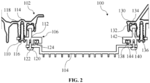
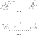
- FIG. 2 to FIG. 3B illustrate a vehicle light 100 and its constituent components according to a first embodiment of the present disclosure.
- the vehicle light 100 may be a light on a vehicle for providing illumination and/or signaling, such as headlight, taillight, turn light, etc.
- the vehicle light 100 includes a housing 102, a lighting drive module 104, and a mounting bracket 106.
- the housing 102 is configured to accommodate a lighting module (not shown).
- the lighting drive module 104 is configured to drive/control the lighting module to provide desired illumination effect and/or signaling effect.
- the mounting bracket 106 and the housing 102 are separately formed and the mounting bracket 106 is fixed to the housing 102.
- the lighting drive module 104 is fixed to the mounting bracket 106.
- the housing 102 and the mounting bracket 106 may be separately formed by injection molding.
- the lighting drive module is fixed to the housing of the vehicle light via the mounting bracket
- adjusting the configuration and/or size of the mounting bracket allows lighting drive modules in different configurations and/or sizes to be mounted to the housing of the vehicle light without changing the size and/or configuration of the housing of the vehicle light. That is, there is no need to design and manufacture housings of different specifications to adapt to lighting drive modules in different configurations and/or sizes, thereby reducing the cost of making the mold for the housing.
- the mounting bracket has a smaller volume and relatively simpler structure compared to the housing, the above configuration can further reduce the overall design and manufacturing cost of the vehicle light.
- the mounting bracket 106 may be in the form of a frame.
- the mounting bracket 106 may include a bracket body 108.
- the bracket body 108 may be provided with multiple first fastening portions 110 and multiple second fastening portions 112.
- the mounting bracket 106 may be fixed to the housing 102 by means of the multiple first fastening portions 110, and the mounting bracket 106 may be fixed to the lighting drive module 104 by means of the multiple second fastening portions 112, so that the lighting drive module 104 can be mounted to the housing 102 via the mounting bracket 106.
- the bracket body 108 extends substantially along a plane, such that the multiple first fastening portions 110 and the multiple second fastening portions 112 are substantially located in the same plane.
- Each of the multiple first fastening portions 110 may be in the form of an opening.
- the housing 102 may include multiple first fastening holes 114.
- the vehicle light 100 may further include multiple first fasteners 116, and each first fastener 116 may be at least partially received in the corresponding first fastening portion 110 and first fastening hole 114 to fix the mounting bracket 106 to the housing 102.
- each first fastening portion 110 may extend through the bracket body 108.
- Each first fastening hole 114 may be provided/opened in a first boss 118 on the housing 102 and include internal threads.
- Each first fastener 116 may be an external threaded fastener such as a bolt or screw and be passed through the corresponding first fastening portion 110 and screwed into the corresponding first fastening hole 114. It is conceivable that the method and structure for fixing the mounting bracket with the housing are not limited thereto, and the mounting bracket may also be fixed to the housing by means of, for example, snap connection.
- Each of the multiple second fastening portions 112 may be in the form of an opening.
- the lighting drive module 104 may include multiple second fastening holes 120.
- the vehicle light 100 may further include multiple second fasteners 122, and each second fastener 122 may be adapted to be at least partially received in the corresponding second fastening portion 112 and second fastening hole 120 to fix the lighting drive module 104 to the mounting bracket 106.
- each second fastening portion 112 may be provided/opened in a second boss 124 on the bracket body 108 and include internal threads.
- the lighting drive module 104 may include a module body 126 and multiple fastening lugs 128 arranged around the module body 126.
- Each second fastening hole 120 may extend through the corresponding fastening lug 128.
- Each second fastener 122 may be an external threaded fastener such as a bolt or screw and be passed through the corresponding second fastening hole 120 and screwed into the corresponding second fastening portion 112.
- the positions of the multiple second fastening portions of the mounting bracket can be changed accordingly, so that each second fastening portion can be aligned with the corresponding second fastening hole, allowing the lighting drive module to be fixed to the mounting bracket via multiple second fasteners.
- the method and structure for fixing the mounting bracket with the lighting drive module are not limited thereto, and the lighting drive module may also be fixed to the mounting bracket by means of, for example, snap connection.
- a first seal 130 is provided between the housing 102 and the mounting bracket 106.
- a first accommodating groove 132 may be provided in the housing 102 to accommodate the first seal 130.
- a first rib 134 is provided on a bottom wall of the first accommodating groove 132 of the housing 102, and accordingly, a second rib 136 is provided on the bracket body 108 of the mounting bracket 106.
- the first seal 130, the first rib 134 and the second rib 136 may all be ring-shaped. It is conceivable that the first accommodating groove may also be provided in the mounting bracket. It is also conceivable that the rib may be only provided on one of the housing and the mounting bracket to compress the first seal.
- a second seal 138 is provided between the mounting bracket 106 and the lighting drive module 104.
- a second accommodating groove 140 may be provided in the mounting bracket 106 to accommodate the second seal 138.
- a third rib 142 is provided on a bottom wall of the second accommodating groove 140 of the mounting bracket 106, and accordingly, a fourth rib 144 is provided on the lighting drive module 104.
- the second seal 138, the third rib 142 and the fourth rib 144 may all be ring-shaped. It is conceivable that the second accommodating groove may also be provided in the lighting drive module. It is also conceivable that the rib may be only provided on one of the lighting drive module and the mounting bracket to compress the second seal.
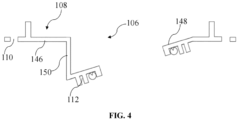
- FIG. 4 shows the mounting bracket of the vehicle light according to the second embodiment of the present disclosure.
- the housing and lighting drive module of the vehicle light according to the first embodiment have the same structure as the housing and lighting drive module of the vehicle light according to the second embodiment.
- the mounting bracket of the vehicle light according to the first embodiment differs from the mounting bracket of the vehicle light according to the second embodiment in that: the bracket body 108 of the mounting bracket 106 of the vehicle light according to the second embodiment includes a first body section 146 and a second body section 148 that are connected to each other and are not coplanar, wherein the multiple first fastening portions 110 are provided at the first body section 146, and the multiple second fastening portions 112 are provided at the second body section 148.
- the following description focuses on the differences between the two embodiments, and the similarities are not repeated.
- the bracket body 108 of the mounting bracket 106 for the vehicle light includes a first body section 146, a second body section 148, and a third body section 150.
- a part of the first body section 146 is connected to the second body section 148 via the third body section 150, and another part of the first body section 146 is directly connected to the second body section 148.
- the extension plane of the first body section 146 and the extension plane of the second body section 148 are at a certain angle to each other, such that the multiple first fastening portions 110 on the first body section 146 and the multiple second fastening portions 112 on the second body section 148 are located on different planes which are at an angle to each other.
- the structure of the bracket body 108 of the mounting bracket 106 is advantageous for situations where there exist other components, which may occupy the installation space of the lighting drive module, in the installation environment around the vehicle light.
- the irregular structure of the bracket body 108 of the mounting bracket 106 can avoid the components around the vehicle light, so that the lighting drive module can be successfully installed. It is conceivable that the structure of the bracket body of the mounting bracket is not limited thereto, but can be reasonably designed according to the structure and size of the components in the surrounding environment of the vehicle light, as well as the structure and size of the lighting drive module.
- FIG. 2 to FIG. 4 only illustrate the shape, size and arrangement of the optional components of the vehicle light according to the present disclosure. However, these embodiments are merely intended to illustrate, rather than to limit. Other shapes, sizes and arrangements may be adopted without departing from the idea and scope of the present disclosure.
Landscapes
- Engineering & Computer Science (AREA)
- General Engineering & Computer Science (AREA)
- Microelectronics & Electronic Packaging (AREA)
- Mechanical Engineering (AREA)
- Lighting Device Outwards From Vehicle And Optical Signal (AREA)
- Non-Portable Lighting Devices Or Systems Thereof (AREA)
Abstract
The present disclosure provides a vehicle light. The vehicle light (100) includes: a housing (102) configured to accommodate a lighting module (104) of the vehicle light (100); a lighting drive module (104) configured to drive the lighting module (100); and a mounting bracket (106); wherein the mounting bracket (106) and the housing (102) are separately formed and the mounting bracket (106) is fixed to the housing (102); wherein the lighting drive module (104) is fixed to the mounting bracket (106). The vehicle light (100) according to the present disclosure can be adapted to lighting drive modules (104) in various structures and/or sizes by means of the mounting bracket (106), thereby reducing the design and manufacturing cost of the vehicle light.
Description
- The present disclosure generally relates to the technical field of vehicles, and more particularly, to vehicle lights.
- As shown in
FIG. 1 , an existingvehicle light 1 generally includes ahousing 2, a lighting module accommodated in thehousing 2, and a lighting drive module 3 (LDM) fixed to thehousing 2. Thelighting drive module 3 can be fixed to thehousing 2 viafasteners 4. Typically, thehousing 2 is formed by injection molding, and is provided withfastening points 5 for receiving thefasteners 4. If anotherlighting drive module 3 having a different size needs to be mounted, the positions of thefastening points 5 on thehousing 2 need to be changed. In other words, different housing molds need to be made to injection mold different housings, so as to adapt to lighting drive modules in different sizes. This will increase the design and manufacturing cost of vehicle lights. - It is an object of the present disclosure to provide an improved vehicle light to address the above issues in the prior art.
- For this object, the present disclosure provides a vehicle light including: a housing configured to accommodate a lighting module of the vehicle light; a lighting drive module configured to drive the lighting module; and a mounting bracket; wherein the mounting bracket and the housing are separately formed and the mounting bracket is fixed to the housing; wherein the lighting drive module is fixed to the mounting bracket.
- Since the lighting drive module is fixed to the housing of the vehicle light via the mounting bracket, adjusting the configuration and/or size of the mounting bracket allows lighting drive modules in different configurations and/or sizes to be mounted to the housing of the vehicle light without changing the size and/or configuration of the housing of the vehicle light. That is, there is no need to design and manufacture housings of different specifications to adapt to lighting drive modules in different configurations and/or sizes, thereby reducing the cost of making the mold for the housing. As the mounting bracket has a smaller volume and relatively simpler structure compared to the housing, the above configuration can further reduce the overall design and manufacturing cost of the vehicle light.
- According to the above technical concept, the present disclosure may further include one or more of the following optional embodiments.
- In some optional embodiments, the mounting bracket includes a bracket body, and the bracket body is provided with multiple first fastening portions and multiple second fastening portions, wherein the mounting bracket is adapted to be fixed to the housing via the multiple first fastening portions and fixed to the lighting drive module via the multiple second fastening portions.
- In some optional embodiments, the bracket body extends substantially along a plane, such that the multiple first fastening portions and the multiple second fastening portions are substantially located in the same plane.
- In some optional embodiments, the bracket body includes a first body section and a second body section that are connected to each other and are not coplanar, wherein the multiple first fastening portions are provided at the first body section, and the multiple second fastening portions are provided at the second body section.
- In some optional embodiments, each of the first fastening portions is in the form of an opening, and the housing includes multiple first fastening holes; wherein the vehicle light further includes multiple first fasteners, and each first fastener is adapted to be at least partially received in the corresponding first fastening portion and first fastening hole to fix the mounting bracket to the housing.
- In some optional embodiments, each of the second fastening portions is in the form of an opening, and the lighting drive module includes multiple second fastening holes; wherein the vehicle light further includes multiple second fasteners, and each second fastener is adapted to be at least partially received in the corresponding second fastening portion and second fastening hole to fix the lighting drive module to the mounting bracket.
- In some optional embodiments, a first seal is provided between the housing and the mounting bracket; and/or a second seal is provided between the mounting bracket and the lighting drive module.
- In some optional embodiments, the mounting bracket includes at least one accommodating groove for accommodating the first seal and/or the second seal.
- In some optional embodiments, the mounting bracket includes at least one rib for compressing the first seal and/or the second seal.
- In some optional embodiments, the mounting bracket is in the form of a frame and is formed by injection molding.
- The vehicle light according to the present disclosure can be adapted to lighting drive modules in various configurations and/or sizes by means of the mounting bracket, thereby reducing the design and manufacturing cost of the vehicle light.
- Other features and advantages of the present disclosure will be readily understood through the following optional embodiments described in detail with reference to the accompanying drawings, in which the same reference numerals indicate the same or similar components, and
-
FIG. 1 is a perspective view of a vehicle light in the background technology; -
FIG. 2 is a partially sectioned view of a vehicle light according to a first embodiment of the present disclosure; -
FIG. 3A is a cross-sectional view of a mounting bracket of the vehicle light inFIG. 2 ; -
FIG. 3B is a cross-sectional view of a lighting drive module of the vehicle light inFIG. 2 ; and -
FIG. 4 is a cross-sectional view of the mounting bracket of the vehicle light according to a second embodiment of the present disclosure. - The implementation and usage of the embodiments are discussed in detail below. However, it should be understood that the specific embodiments discussed herein are merely intended to illustrate specific ways of implementing and using the present disclosure, and are not intended to limit the scope of the present disclosure. In describing structures and positions of various components of a vehicle, the orientation-related expressions, such as "upper", "lower", "top", "bottom", "front" and "rear", are not absolute, but relative.
- The terms, such as "first" and "second", are only used for description, and should not be construed as indicating or implying relative importance or implicitly indicating the number of technical features referred to. In the present disclosure, unless otherwise specified, the terms, such as "mounting", "joining", "connection", and "fixation", should be understood in a broad sense. For example, "connection" may be a fixed connection, a detachable connection, or an integral connection; a direct connection or an indirect connection via an intermediary. For those skilled in the art, specific meanings of the above terms in the present disclosure should be understood according to specific circumstances.
-
FIG. 2 to FIG. 3B illustrate avehicle light 100 and its constituent components according to a first embodiment of the present disclosure. Thevehicle light 100 may be a light on a vehicle for providing illumination and/or signaling, such as headlight, taillight, turn light, etc. - Referring to
FIG. 2 to FIG. 3B , thevehicle light 100 includes ahousing 102, alighting drive module 104, and amounting bracket 106. Thehousing 102 is configured to accommodate a lighting module (not shown). Thelighting drive module 104 is configured to drive/control the lighting module to provide desired illumination effect and/or signaling effect. Themounting bracket 106 and thehousing 102 are separately formed and themounting bracket 106 is fixed to thehousing 102. Thelighting drive module 104 is fixed to themounting bracket 106. Optionally, thehousing 102 and themounting bracket 106 may be separately formed by injection molding. - Since the lighting drive module is fixed to the housing of the vehicle light via the mounting bracket, adjusting the configuration and/or size of the mounting bracket allows lighting drive modules in different configurations and/or sizes to be mounted to the housing of the vehicle light without changing the size and/or configuration of the housing of the vehicle light. That is, there is no need to design and manufacture housings of different specifications to adapt to lighting drive modules in different configurations and/or sizes, thereby reducing the cost of making the mold for the housing. As the mounting bracket has a smaller volume and relatively simpler structure compared to the housing, the above configuration can further reduce the overall design and manufacturing cost of the vehicle light.
- Referring to
FIG. 2 to FIG. 3B , themounting bracket 106 may be in the form of a frame. Themounting bracket 106 may include abracket body 108. Thebracket body 108 may be provided with multiple first fasteningportions 110 and multiplesecond fastening portions 112. Themounting bracket 106 may be fixed to thehousing 102 by means of the multiplefirst fastening portions 110, and themounting bracket 106 may be fixed to thelighting drive module 104 by means of the multiplesecond fastening portions 112, so that thelighting drive module 104 can be mounted to thehousing 102 via themounting bracket 106. As shown inFIG. 2 to FIG. 3B , thebracket body 108 extends substantially along a plane, such that the multiple first fasteningportions 110 and the multiple second fasteningportions 112 are substantially located in the same plane. - Each of the multiple first fastening
portions 110 may be in the form of an opening. Thehousing 102 may include multiplefirst fastening holes 114. Thevehicle light 100 may further include multiplefirst fasteners 116, and eachfirst fastener 116 may be at least partially received in the correspondingfirst fastening portion 110 andfirst fastening hole 114 to fix the mountingbracket 106 to thehousing 102. - As shown in
FIG. 2 to FIG. 3B , eachfirst fastening portion 110 may extend through thebracket body 108. Eachfirst fastening hole 114 may be provided/opened in afirst boss 118 on thehousing 102 and include internal threads. Eachfirst fastener 116 may be an external threaded fastener such as a bolt or screw and be passed through the correspondingfirst fastening portion 110 and screwed into the correspondingfirst fastening hole 114. It is conceivable that the method and structure for fixing the mounting bracket with the housing are not limited thereto, and the mounting bracket may also be fixed to the housing by means of, for example, snap connection. - Each of the multiple
second fastening portions 112 may be in the form of an opening. Thelighting drive module 104 may include multiple second fastening holes 120. Thevehicle light 100 may further include multiplesecond fasteners 122, and eachsecond fastener 122 may be adapted to be at least partially received in the correspondingsecond fastening portion 112 andsecond fastening hole 120 to fix thelighting drive module 104 to the mountingbracket 106. - As shown in
FIG. 2 to FIG. 3B , eachsecond fastening portion 112 may be provided/opened in asecond boss 124 on thebracket body 108 and include internal threads. Thelighting drive module 104 may include amodule body 126 and multiple fastening lugs 128 arranged around themodule body 126. Eachsecond fastening hole 120 may extend through thecorresponding fastening lug 128. Eachsecond fastener 122 may be an external threaded fastener such as a bolt or screw and be passed through the correspondingsecond fastening hole 120 and screwed into the correspondingsecond fastening portion 112. - It is conceivable that, in a case that the size of the lighting drive module to be mounted is changed (in other words, the positions of the multiple second fastening holes on the lighting drive module are changed), the positions of the multiple second fastening portions of the mounting bracket can be changed accordingly, so that each second fastening portion can be aligned with the corresponding second fastening hole, allowing the lighting drive module to be fixed to the mounting bracket via multiple second fasteners.
- It is conceivable that the method and structure for fixing the mounting bracket with the lighting drive module are not limited thereto, and the lighting drive module may also be fixed to the mounting bracket by means of, for example, snap connection.
- As shown in
FIG. 2 to FIG. 3B , afirst seal 130 is provided between thehousing 102 and the mountingbracket 106. A firstaccommodating groove 132 may be provided in thehousing 102 to accommodate thefirst seal 130. Afirst rib 134 is provided on a bottom wall of the firstaccommodating groove 132 of thehousing 102, and accordingly, asecond rib 136 is provided on thebracket body 108 of the mountingbracket 106. When the mountingbracket 106 is fixed to thehousing 102, thefirst rib 134 and thesecond rib 136 are aligned with each other and compress thefirst seal 130 therebetween, such that thefirst seal 130 reaches a predetermined compression ratio, thereby achieving a desirable sealing effect. Thefirst seal 130, thefirst rib 134 and thesecond rib 136 may all be ring-shaped. It is conceivable that the first accommodating groove may also be provided in the mounting bracket. It is also conceivable that the rib may be only provided on one of the housing and the mounting bracket to compress the first seal. - As shown in
FIG. 2 to FIG. 3B , a second seal 138 is provided between the mountingbracket 106 and thelighting drive module 104. A secondaccommodating groove 140 may be provided in the mountingbracket 106 to accommodate the second seal 138. Athird rib 142 is provided on a bottom wall of the secondaccommodating groove 140 of the mountingbracket 106, and accordingly, afourth rib 144 is provided on thelighting drive module 104. When thelighting drive module 104 is fixed to the mountingbracket 106, thethird rib 142 and thefourth rib 144 are aligned with each other and compress the second seal 138 therebetween, such that the second seal 138 reaches a predetermined compression ratio, thereby achieving a desirable sealing effect. The second seal 138, thethird rib 142 and thefourth rib 144 may all be ring-shaped. It is conceivable that the second accommodating groove may also be provided in the lighting drive module. It is also conceivable that the rib may be only provided on one of the lighting drive module and the mounting bracket to compress the second seal. -
FIG. 4 shows the mounting bracket of the vehicle light according to the second embodiment of the present disclosure. The housing and lighting drive module of the vehicle light according to the first embodiment have the same structure as the housing and lighting drive module of the vehicle light according to the second embodiment. The mounting bracket of the vehicle light according to the first embodiment differs from the mounting bracket of the vehicle light according to the second embodiment in that: thebracket body 108 of the mountingbracket 106 of the vehicle light according to the second embodiment includes afirst body section 146 and asecond body section 148 that are connected to each other and are not coplanar, wherein the multiplefirst fastening portions 110 are provided at thefirst body section 146, and the multiplesecond fastening portions 112 are provided at thesecond body section 148. The following description focuses on the differences between the two embodiments, and the similarities are not repeated. - Referring to
FIG. 4 , thebracket body 108 of the mountingbracket 106 for the vehicle light according to the second embodiment includes afirst body section 146, asecond body section 148, and athird body section 150. A part of thefirst body section 146 is connected to thesecond body section 148 via thethird body section 150, and another part of thefirst body section 146 is directly connected to thesecond body section 148. The extension plane of thefirst body section 146 and the extension plane of thesecond body section 148 are at a certain angle to each other, such that the multiplefirst fastening portions 110 on thefirst body section 146 and the multiplesecond fastening portions 112 on thesecond body section 148 are located on different planes which are at an angle to each other. The structure of thebracket body 108 of the mountingbracket 106 is advantageous for situations where there exist other components, which may occupy the installation space of the lighting drive module, in the installation environment around the vehicle light. The irregular structure of thebracket body 108 of the mountingbracket 106 can avoid the components around the vehicle light, so that the lighting drive module can be successfully installed. It is conceivable that the structure of the bracket body of the mounting bracket is not limited thereto, but can be reasonably designed according to the structure and size of the components in the surrounding environment of the vehicle light, as well as the structure and size of the lighting drive module. - It should also be understood that the various components and features described herein can be made of a variety of materials, including, but not limited to, polymer, rubber, metal and other suitable materials familiar to those skilled in the art or combinations thereof. The embodiments shown in
FIG. 2 to FIG. 4 only illustrate the shape, size and arrangement of the optional components of the vehicle light according to the present disclosure. However, these embodiments are merely intended to illustrate, rather than to limit. Other shapes, sizes and arrangements may be adopted without departing from the idea and scope of the present disclosure. - The technical contents and technical features of the present disclosure have been disclosed as above. However, it is conceivable that under the creative concept of the present disclosure, those skilled in the art can easily make modifications, variants and equivalents of these embodiments according to the disclosure. For example, features shown or described as part of one embodiment may be combined with another embodiment to produce another embodiment. The present disclosure is intended to cover these modifications, variants and equivalents. The description of the foregoing embodiments is illustrative rather than restrictive, and the scope of protection of the present disclosure is determined by the appended claims.
Claims (10)
- A vehicle light (100) comprising:a housing (102) configured to accommodate a lighting module of the vehicle light (100);a lighting drive module (104) configured to drive the lighting module; anda mounting bracket (106), the mounting bracket (106) and the housing (102) being separately formed, the mounting bracket (106) being fixed to the housing (102);wherein the lighting drive module (104) is fixed to the mounting bracket (106).
- The vehicle light (100) according to claim 1, wherein the mounting bracket (106) comprises a bracket body (108), and the bracket body (108) is provided with a plurality of first fastening portions (110) and a plurality of second fastening portions (112), wherein the mounting bracket (106) is adapted to be fixed to the housing (102) via the plurality of first fastening portions (110) and fixed to the lighting drive module (104) via the plurality of second fastening portions (112).
- The vehicle light (100) according to claim 2, wherein the bracket body (108) extends substantially along a plane, such that the plurality of first fastening portions (110) and the plurality of second fastening portions (112) are substantially located in the same plane.
- The vehicle light (100) according to claim 2, wherein the bracket body (108) comprises a first body section (146) and a second body section (148) that are connected to each other and are not coplanar, wherein the plurality of first fastening portions (110) are provided at the first body section (146), and the plurality of second fastening portions (112) are provided at the second body section (148).
- The vehicle light (100) according to any one of claims 2 to 4, wherein the first fastening portion (110) is in the form of an opening, and the housing (102) comprises a plurality of first fastening holes (114); wherein the vehicle light (100) further comprises a plurality of first fasteners (116), and each first fastener (116) is adapted to be at least partially received in corresponding first fastening portion (110) and first fastening hole (114) to fix the mounting bracket (106) to the housing (102).
- The vehicle light (100) according to any one of claims 2 to 4, wherein the second fastening portion (112) is in the form of an opening, and the lighting drive module (104) comprises a plurality of second fastening holes (120); wherein the vehicle light (100) further comprises a plurality of second fasteners (122), and each second fastener (122) is adapted to be at least partially received in corresponding second fastening portion (112) and second fastening hole (120) to fix the mounting bracket (106) to the lighting drive module (104).
- The vehicle light (100) according to any one of claims 1 to 4, wherein a first seal (130) is provided between the housing (102) and the mounting bracket (106); and a second seal (138) is provided between the mounting bracket (106) and the lighting drive module (104).
- The vehicle light (100) according to claim 7, wherein the mounting bracket (106) comprises at least one accommodating groove (140) for accommodating the first seal (130) and/or the second seal (138).
- The vehicle light (100) according to claim 7, wherein the mounting bracket (106) comprises at least one rib (136, 142) for compressing the first seal (130) and/or the second seal (138).
- The vehicle light (100) according to any one of claims 1 to 4, wherein the mounting bracket (106) is in the form of a frame and is formed by injection molding.
Applications Claiming Priority (1)
| Application Number | Priority Date | Filing Date | Title |
|---|---|---|---|
| CN202311349235.7A CN119844748A (en) | 2023-10-17 | 2023-10-17 | Car light |
Publications (1)
| Publication Number | Publication Date |
|---|---|
| EP4541658A1 true EP4541658A1 (en) | 2025-04-23 |
Family
ID=93119768
Family Applications (1)
| Application Number | Title | Priority Date | Filing Date |
|---|---|---|---|
| EP24206340.2A Pending EP4541658A1 (en) | 2023-10-17 | 2024-10-14 | Vehicle light |
Country Status (2)
| Country | Link |
|---|---|
| EP (1) | EP4541658A1 (en) |
| CN (1) | CN119844748A (en) |
Citations (6)
| Publication number | Priority date | Publication date | Assignee | Title |
|---|---|---|---|---|
| US5722768A (en) * | 1995-06-28 | 1998-03-03 | Koito Manufacturing Co., Ltd. | Lamp utilizing discharge bulb as light source and having reduced size |
| US6161951A (en) * | 1997-11-11 | 2000-12-19 | Koito Manufacturing | Vehicular headlamp |
| JP2004362975A (en) * | 2003-06-05 | 2004-12-24 | Koito Mfg Co Ltd | Electronic equipment |
| US20080266892A1 (en) * | 2007-04-26 | 2008-10-30 | Koito Manufacturing Co., Ltd. | Vehicle headlight |
| FR3003336A1 (en) * | 2013-03-18 | 2014-09-19 | Valeo Vision | SIGNALING AND / OR LIGHTING DEVICES FOR MOTOR VEHICLES |
| JP2022086255A (en) * | 2020-11-30 | 2022-06-09 | 株式会社小糸製作所 | Vehicular lamp fitting |
-
2023
- 2023-10-17 CN CN202311349235.7A patent/CN119844748A/en active Pending
-
2024
- 2024-10-14 EP EP24206340.2A patent/EP4541658A1/en active Pending
Patent Citations (6)
| Publication number | Priority date | Publication date | Assignee | Title |
|---|---|---|---|---|
| US5722768A (en) * | 1995-06-28 | 1998-03-03 | Koito Manufacturing Co., Ltd. | Lamp utilizing discharge bulb as light source and having reduced size |
| US6161951A (en) * | 1997-11-11 | 2000-12-19 | Koito Manufacturing | Vehicular headlamp |
| JP2004362975A (en) * | 2003-06-05 | 2004-12-24 | Koito Mfg Co Ltd | Electronic equipment |
| US20080266892A1 (en) * | 2007-04-26 | 2008-10-30 | Koito Manufacturing Co., Ltd. | Vehicle headlight |
| FR3003336A1 (en) * | 2013-03-18 | 2014-09-19 | Valeo Vision | SIGNALING AND / OR LIGHTING DEVICES FOR MOTOR VEHICLES |
| JP2022086255A (en) * | 2020-11-30 | 2022-06-09 | 株式会社小糸製作所 | Vehicular lamp fitting |
Also Published As
| Publication number | Publication date |
|---|---|
| CN119844748A (en) | 2025-04-18 |
Similar Documents
| Publication | Publication Date | Title |
|---|---|---|
| US7458824B2 (en) | Electric junction box including electric unit in plural shield case members | |
| US12275302B2 (en) | Powertrain and vehicle including same | |
| US20100001554A1 (en) | Vehicle body pass-through structure | |
| JP2003272754A (en) | Control circuit module for vehicle, control device for electric load mounted on vehicle, control circuit module for control device for automatic transmission to which it is applied | |
| US11769993B2 (en) | Electrical junction box housing | |
| CN119844748A (en) | Car light | |
| US20230128060A1 (en) | Compressor | |
| CN214728480U (en) | High-order brake lamp | |
| CN216850438U (en) | Device for installing man-machine interface and man-machine interface kit | |
| US4420803A (en) | Housing for forming a vehicle light assembly | |
| CN212219848U (en) | Mounting structure for fixed glass of automobile front door | |
| JP3154909B2 (en) | Mounting structure for vehicle lighting | |
| CN113217221A (en) | Cylinder head cover assembly, engine and vehicle | |
| CN222811621U (en) | Lighting assembly and vehicle | |
| CN222995797U (en) | Antenna assembly and vehicle | |
| CN221315802U (en) | Special-shaped instrument | |
| CN219172284U (en) | Front bumper and headlight matched mounting structure and vehicle with same | |
| CN111409566A (en) | Mounting assembly of vehicle-mounted camera and vehicle | |
| CN223644715U (en) | Camera mounting assembly and vehicle | |
| CN222010370U (en) | Engine air filter box and engine air filter | |
| CN219406280U (en) | Headlight installation assembly and vehicle | |
| CN214064722U (en) | Lamp housing assembly and messenger wire lamp | |
| CN223076825U (en) | Directional lighting fixtures and lighting systems | |
| CN220648169U (en) | Driving control module structure of automobile headlight | |
| CN212637666U (en) | Side wall assembly and car |
Legal Events
| Date | Code | Title | Description |
|---|---|---|---|
| PUAI | Public reference made under article 153(3) epc to a published international application that has entered the european phase |
Free format text: ORIGINAL CODE: 0009012 |
|
| STAA | Information on the status of an ep patent application or granted ep patent |
Free format text: STATUS: THE APPLICATION HAS BEEN PUBLISHED |
|
| AK | Designated contracting states |
Kind code of ref document: A1 Designated state(s): AL AT BE BG CH CY CZ DE DK EE ES FI FR GB GR HR HU IE IS IT LI LT LU LV MC ME MK MT NL NO PL PT RO RS SE SI SK SM TR |
|
| STAA | Information on the status of an ep patent application or granted ep patent |
Free format text: STATUS: REQUEST FOR EXAMINATION WAS MADE |
|
| 17P | Request for examination filed |
Effective date: 20250923 |