EP4541611A1 - Verbundlenkerachse - Google Patents
Verbundlenkerachse Download PDFInfo
- Publication number
- EP4541611A1 EP4541611A1 EP24204235.6A EP24204235A EP4541611A1 EP 4541611 A1 EP4541611 A1 EP 4541611A1 EP 24204235 A EP24204235 A EP 24204235A EP 4541611 A1 EP4541611 A1 EP 4541611A1
- Authority
- EP
- European Patent Office
- Prior art keywords
- torsion profile
- wall
- bevel
- beam axle
- torsion
- Prior art date
- Legal status (The legal status is an assumption and is not a legal conclusion. Google has not performed a legal analysis and makes no representation as to the accuracy of the status listed.)
- Pending
Links
Images
Classifications
-
- B—PERFORMING OPERATIONS; TRANSPORTING
- B60—VEHICLES IN GENERAL
- B60G—VEHICLE SUSPENSION ARRANGEMENTS
- B60G21/00—Interconnection systems for two or more resiliently-suspended wheels, e.g. for stabilising a vehicle body with respect to acceleration, deceleration or centrifugal forces
- B60G21/02—Interconnection systems for two or more resiliently-suspended wheels, e.g. for stabilising a vehicle body with respect to acceleration, deceleration or centrifugal forces permanently interconnected
- B60G21/04—Interconnection systems for two or more resiliently-suspended wheels, e.g. for stabilising a vehicle body with respect to acceleration, deceleration or centrifugal forces permanently interconnected mechanically
- B60G21/05—Interconnection systems for two or more resiliently-suspended wheels, e.g. for stabilising a vehicle body with respect to acceleration, deceleration or centrifugal forces permanently interconnected mechanically between wheels on the same axle but on different sides of the vehicle, i.e. the left and right wheel suspensions being interconnected
- B60G21/051—Trailing arm twist beam axles
-
- B—PERFORMING OPERATIONS; TRANSPORTING
- B60—VEHICLES IN GENERAL
- B60G—VEHICLE SUSPENSION ARRANGEMENTS
- B60G2200/00—Indexing codes relating to suspension types
- B60G2200/20—Semi-rigid axle suspensions
- B60G2200/21—Trailing arms connected by a torsional beam, i.e. twist-beam axles
-
- B—PERFORMING OPERATIONS; TRANSPORTING
- B60—VEHICLES IN GENERAL
- B60G—VEHICLE SUSPENSION ARRANGEMENTS
- B60G2200/00—Indexing codes relating to suspension types
- B60G2200/20—Semi-rigid axle suspensions
- B60G2200/23—Trailing arms connected by a U-shaped torsion bar
-
- B—PERFORMING OPERATIONS; TRANSPORTING
- B60—VEHICLES IN GENERAL
- B60G—VEHICLE SUSPENSION ARRANGEMENTS
- B60G2206/00—Indexing codes related to the manufacturing of suspensions: constructional features, the materials used, procedures or tools
- B60G2206/01—Constructional features of suspension elements, e.g. arms, dampers, springs
- B60G2206/20—Constructional features of semi-rigid axles, e.g. twist beam type axles
-
- B—PERFORMING OPERATIONS; TRANSPORTING
- B60—VEHICLES IN GENERAL
- B60G—VEHICLE SUSPENSION ARRANGEMENTS
- B60G2206/00—Indexing codes related to the manufacturing of suspensions: constructional features, the materials used, procedures or tools
- B60G2206/01—Constructional features of suspension elements, e.g. arms, dampers, springs
- B60G2206/80—Manufacturing procedures
- B60G2206/82—Joining
- B60G2206/8201—Joining by welding
Definitions
- the invention relates to a twist beam axle for motor vehicles according to the features in the preamble of claim 1.
- a twist-beam axle features two flexurally and torsionally rigid side arms and a transversely extending torsion profile that connects the side arms in a torsionally flexible manner.
- a twist-beam axle is characterized by good lateral control when cornering, as well as its compact size and low weight.
- a twist beam axle with a V-shaped torsion profile in cross-section is, for example, characterized by the DE 27 359 39 C2 or the EP 0 916 530 B1 known.
- the torsion profile is welded to the side arms.
- the torsion profile and the side arms often have different wall thicknesses.
- the torsion profile has a greater wall thickness than the side arms.
- the invention is based on the object of improving the load behavior of a twist beam axle and increasing its service life without adversely increasing its weight.
- a twist beam axle has two side arms and a torsion profile that connects the two side arms in a torsionally flexible manner.
- the torsion profile is connected to each of the side arms by a welded joint.
- the torsion profile has a wall with a wall thickness and the side arms each have a wall with a wall thickness.
- the wall thickness of the wall of the torsion profile is, at least in the area of the welded joint, greater than the wall thickness of the wall of a side arm in the area of the welded joint.
- the torsion profile has a joining surface at each end section.
- Each side arm also has a joining surface.
- the torsion profile and the side arms are each connected by a weld at their mutually facing joining surfaces.
- the joining surface has a bevel at each end section of the torsion profile. Due to the bevel, the end section tapers towards the front end of the torsion profile. The end sections of the torsion profile receive seam preparation tailored to the welding process.
- the joining surface is extended by the bevel and tapers towards the end of the end section. Due to the bevel in the joining surface of the end section, the joining gap between the joining surface at the end section of the torsion profile and the joining surface on a side arm takes on a V-shaped configuration.
- the joining gap between the end section of the torsion profile and the side arm has a V-shaped configuration.
- the bevel and the V-shaped joining gap enable a high degree of penetration in the torsion profile. Penetration is the depth of the molten zone in the base material, in this case the steel material of the torsion profile in the end section.
- the penetration is typically between 2% and 10%.
- the invention also allows for higher penetration rates.
- the flank penetration length i.e., the length of the molten area where the filler metal has bonded to the base material, is 70% to 90% of the wall thickness of the components, particularly the wall thickness of the torsion profile.
- the invention creates a twist-beam axle with a longer service life without increasing component weight.
- the advantageous driving dynamics properties and thus the performance with maximum driving stability and comfort are maintained.
- the torsion profile and the side arms are aligned at an angle transverse to each other; in particular, the torsion profile abuts each side arm with a T-joint.
- the end section of the torsion profile has an abutment surface on the front side, wherein the abutment surface runs essentially perpendicular to the longitudinal axis of the wall of the torsion profile.
- the frontal abutment surface is part of the joining surface at the end section of the torsion profile. With the abutment surface, the torsion profile abuts the joining surface on the side arm.
- the slope runs into the front of the end section.
- the joint surface is connected to the slope.
- the abutting surface is significantly shorter than the length of the bevel.
- the abutting surface extends parallel to the joining surface on one side arm.
- the bevel is provided in the areas of the abutting edge where the greatest loads from external forces occur.
- the bevel is provided in particular on the joining surfaces of the legs of the torsion profile.
- the bevel is arranged on the inside of the cross section on the inside of the torsion profile or on the outside of the cross section on the outside of the torsion profile along the legs.
- the bevel is provided on a partial section of the length of one leg of the torsion profile.
- the bevel is provided in the lower longitudinal section of the length of the leg and extends over 30% to 75%, in particular approximately 50%, of the length of one leg.
- the tangential length of the bevel is measured in the cross-section of the torsion profile in the direction of the circumference of the torsion profile and can extend over the entire circumferential length of the end face of the torsion profile.
- the tangential length of the bevel can also run only over the length of one leg or be provided on a partial section of the length of one leg of a torsion profile.
- the joining surface of the torsion profile abuts the joining surface of a side arm.
- the joining surface at the end section of the torsion profile is machined to create the bevel. Material is removed from the end section. This can be done, for example, by milling, turning, or grinding.
- a wedge-shaped edge area is removed at the end of each end section of a torsion profile and the bevel is created in the joining surface.
- the slope runs at an angle to the longitudinal axis of the torsion profile wall, preferably in a range between 25° and 60°.
- An angle in the range of 30° to 45° is considered particularly advantageous in practice.
- the bevel has an axial length, with the axial length being greater than the wall thickness of the torsion profile wall in the end section.
- the ratio of the axial length of the bevel to the wall thickness of the torsion profile wall is between 1:1 and 2:1.
- the axial length of the bevel is measured along the longitudinal axis of the torsion profile wall.
- the abutment surface on the front side of the end section of an end profile has a width, where the width is measured perpendicular to the longitudinal axis of the torsion profile wall.
- the width of the abutment surface is significantly smaller than the wall thickness of the torsion profile wall; in particular, the wall thickness of the torsion profile wall is 3 to 6 times greater than the width of the abutment surface. Accordingly, the ratio of the width of the abutment surface to the wall thickness of the torsion profile wall in the end section is between 1:3 and 1:6.
- the twist-beam axle To manufacture the twist-beam axle, two side arms and a torsion profile are provided.
- the components of the twist-beam axle are made of steel.
- the torsion profile and the side arms have different wall thicknesses, at least in the area of the welded joint. This means, in particular, that the wall thickness of the torsion profile is greater than the wall thickness of the a side arm.
- the torsion profile and the side arms are arranged at an angle to each other and connected by a weld.
- a blank is provided with a wall of a certain thickness.
- a bevel is formed at the end section of the blank, and a butt surface is created at the end section.
- the initial blank is formed into a torsion profile.
- the initial blank is given a cross-sectional configuration of the torsion profile, at least in certain areas, particularly along its length.
- the initial blank is formed, in particular, around its longitudinal axis and provided with the cross-section of the torsion profile, for example, a U- or V-shaped cross-section.
- the side arms are provided.
- the side arms have a wall thickness that differs from the wall thickness of the torsion profile.
- the torsion profile and the side arms are aligned at an angle relative to each other so that the joining surface of the torsion profile and the joining surfaces of the side arms face each other.
- the torsion profile and side arms are then joined by a weld seam at the joining surfaces.
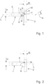
- FIGS. 1 and 2 show sections of components of a twist beam axle for a motor vehicle.
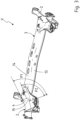
- a twist beam axle V in a perspective view is shown in the Figure 3 shown.
- a twist beam axle V essentially comprises two wheel-guiding side arms 2 and a torsion profile 1 connecting the two side arms 2.
- the torsion profile is designated by the reference numeral 1 and a side arm by the reference numeral 2.
- the torsion profile 1 has a wall 3 with a wall thickness t1.
- the side arm(s) 2 each have a wall 4 with a wall thickness t2.
- the wall thickness t1 of wall 3 of the torsion profile 1 is greater than the wall thickness t2 of wall 4 of the side arm 2.
- the torsion profile 1 has a joining surface 6 at each end section 5.
- the side arms 2 also each have a joining surface 7.
- the torsion profile 1 and the side arms 2 are connected at their mutually facing joining surfaces 6, 7 by a weld seam 8.
- the weld connection with the weld seam 8 is shown in the Figure 2 shown.
- the joining surface 6 at the end section 5 of the torsion profile 1 has a bevel 9.
- the bevel 9 is created by machining the end section 5. Due to the bevel 9, the end section 5 tapers towards the end face 10 of the torsion profile 1.
- the torsion profile 1 and the side arm(s) 2 are positioned relative to each other. This is shown in the illustration of the Figure 1 .
- the joining surfaces 6, 7 face each other.
- a V-shaped joining gap 11 is formed between the joining surface 5 of the torsion profile 1 and the joining surface 6 of a side arm 2.
- the material connection is made via a weld seam, as shown in the Figure 2
- the bevel 9 makes the weld seam 8 significantly more efficient; in particular, a component-optimized penetration in the torsion profile 1 can be achieved.
- the end section 5 of the torsion profile 1 has an abutment surface 12 on its front side.
- the abutment surface 12 extends essentially perpendicular to the longitudinal axis L of the wall 3 of the torsion profile 1.
- the abutment surface 12 is oriented parallel to the joining surface 6 of a side arm 2. At the deepest point of the V-shaped joining gap 11, a gap section is formed parallel between the abutment surface 12 and the joining surface 6.
- the end section 5 tapers at an acute angle ⁇ towards the end face 10.
- the bevel 9 ends at the end face 10.
- the abutting surface 12 adjoins the bevel 9 at an obtuse angle.
- the slope 9 runs at an angle ⁇ to the longitudinal axis L of the wall 3 of the torsion profile 1.
- the angle ⁇ is approximately 30 °.
- the bevel has an axial length I.
- the axial length I is greater than the wall thickness t1 of wall 3 of torsion profile 1.
- the ratio of the axial length I of the bevel 9 to the wall thickness t1 of wall 3 of torsion profile 1 can be between 1:1 and 2:1.
- the abutting surface 12 has a significantly smaller width b compared to the wall thickness t1 of the wall 3 of the torsion profile 1.
- the width b of the abutting surface 12 is measured perpendicular to the longitudinal axis L of the wall 3 of the torsion profile 1.
- the ratio of the width b of the abutting surface 12 to the wall thickness t1 of the wall 3 of the torsion profile 1 can be between 1:3 and 1:6.
- the width b of the abutting surface 12 is 1 mm to 3 mm, inclusive.
- a welded joint between the torsion profile 1 and the side arm 2 is created with a quality that meets the requirements.
- the penetration of the weld seam 8 on the torsion profile 1 can be significantly increased without causing burn-through on the side arm 2.
- the weld seam 8 meets the highest strength requirements, thus increasing the service life of the torsion beam axle without a disadvantageous increase in weight.
- the Figure 3 shows a twist beam axle V.
- the torsion profile 1 abuts with a T-joint to each side arm 2.
- the torsion profile 1 has a wall 3 (see Figures 1 and 2 ) and has a U-shaped cross-sectional profile with two side legs 13, which are connected via an apex section 14. With the end section 5, the torsion profile 1 abuts the wall 4 of a side arm 2.
- the joining surface 6 at the end section 5 of the torsion profile 1 is adapted to the outer contour of the side arm 2 and is curved in an arc shape.
- the arrow P1 schematically illustrates the tangential length of a side leg 13, with which the end section 5 of the torsion profile 1 abuts the outer circumference of the side arm 2. This length amounts to approximately 180° +/- 15° relative to the circumference of the side arm 2, which has a round cross-section.
- the arrow P2 indicates the length of the longitudinal section 15 in which the bevel 9 is provided on the inside of a leg 13 of the torsion profile 1.
- the bevel 9 is provided in the lower longitudinal section 15 of the side leg 13.
- the bevel 9 extends over 30% to 75%, in particular approximately half the length of a side leg 13. Relative to the cross-section of a side arm 2, the bevel 9 extends over a circumferential section of approximately 90° +/-15°.
- the bevel 9 is provided in the lower longitudinal section 15 of a side leg 13, starting from the free leg end.
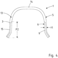
- the Figure 4 shows a front view of the joining surface 6 at an end section 5 of a torsion profile 1.
- the torsion profile 1 has a wall 3 with a wall thickness t1.
- a bevel 9 is provided in the joining surface 6 at the end section 5 of the torsion profile 1.
- the bevel 9 runs on the inside of the side legs 13 of the torsion profile 1.
- the bevel 9 is provided in the lower longitudinal section 15 of the side leg 13, extending from the free leg end.
- the tangential length of the longitudinal section 15 is indicated by the arrow P2.
- the bevel 9 extends approximately over half the length of a side leg 13.
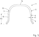
- the Figure 5 shows a front view of the joining surface 6 in an alternative embodiment at the end section 5 of a torsion profile 1.
- the bevel 9 is arranged on the outside of the side legs 13 of the torsion profile.
- the bevel 9 is produced by machining.
- the bevel 9 extends in a lower longitudinal section 15 of each side leg 13, starting from the free leg end. Otherwise, the embodiment corresponds to that of Figure 4 and the corresponding description.
Landscapes
- Engineering & Computer Science (AREA)
- Mechanical Engineering (AREA)
- Vehicle Body Suspensions (AREA)
Abstract
Die Erfindung betrifft eine Verbundlenkerachse, welche zwei Seitenarme 2 und ein Torsionsprofil 1 aufweist. Das Torsionsprofil 1 ist jeweils mit einem Seitenarm 2 durch eine Schweißnaht 8 verbunden. Zumindest im Bereich der Schweißverbindung weist das Torsionsprofil 1 eine Wand 3 mit einer Wandstärke t1 auf, die größer ist als die Wandstärke t2 einer Wand 4 eines Seitenarms 2. Das Torsionsprofil 1 weist an jedem Endabschnitt 5 eine Fügefläche 6 auf und die Seitenarme 2 weisen jeweils eine Fügefläche 7 auf, wobei das Torsionsprofil 1 und die Seitenarme 3 an ihren einander zugewandten Fügeflächen 6, 7 jeweils durch eine Schweißnaht 8 verbunden sind. Die Fügefläche 6 am Endabschnitt 5 des Torsionsprofils 1 weist eine Schräge 9 auf. Der sich zwischen den einander zugewandten Fügeflächen 6, 7 von Endabschnitt 5 und Seitenarm 2 gebildete Fügespalt 11 ist V-förmig konfiguriert. Hierdurch kann der Einbrand der Schweißnaht 8 am Torsionsprofil 1 deutlich erhöht werden.
Description
- Die Erfindung betrifft eine Verbundlenkerachse für Kraftfahrzeuge gemäß den Merkmalen im Oberbegriff von Anspruch 1.
- Eine Verbundlenkerachse weist zwei biege- und verdrehsteife Seitenarme und ein sich zwischen diesen quer erstreckendes Torsionsprofil auf, welches die Seitenarme torsionsweich verbindet. Eine Verbundlenkerachse zeichnet sich durch eine gute Seitenführung bei Kurvenfahrt sowie ihren günstigen Raumbedarf und geringes Gewicht aus.
- Eine Verbundlenkerachse mit einem im Querschnitt V-förmigen Torsionsprofil ist beispielsweise durch die
DE 27 359 39 C2 oder dieEP 0 916 530 B1 bekannt. Das Torsionsprofil ist mit den Seitenarmen verschweißt. - Aufgrund der im Betrieb wirkenden hohen dynamischen und auch statischen Kräften, insbesondere von Längskräften, liegen hohe Belastungen auf der Schweißnaht zwischen dem Torsionsprofil und den Seitenarmen. Der Festigkeit der Schweißnähte und der Schweißnahtqualität kommt daher besondere Bedeutung zu. Die Einbrandtiefe einer Schweißnaht steht dabei in engem Zusammenhang mit der Fügefestigkeit.
- Häufig haben das Torsionsprofil und die Seitenarme unterschiedliche Wandstärken. Üblicherweise weist das Torsionsprofil eine größere Wandstärke auf als die Seitenarme. Bei einer schweißtechnischen Fügung mittels Stumpfstoß hat sich gezeigt, dass es wegen des Wandstärkenunterschieds zwischen Torsionsprofil und Seitenarm schwer ist, einen hohen Einbrand der Schweißnaht in das Torsionsprofil zu erhalten ohne einen Durchbrand am Seitenarm zu erzeugen. Durch den geringeren Einbrand kann es zu einer Reduzierung der Lebensdauer einer Verbundlenkerachse kommen.
- Der Erfindung liegt ausgehend vom Stand der Technik die Aufgabe zugrunde, eine Verbundlenkerachse im Belastungsverhalten zu verbessern und in der Lebensdauer zu steigern ohne deren Gewicht nachteilig zu erhöhen.
- Die Lösung dieser Aufgabe besteht nach der Erfindung in einer Verbundlenkerachse gemäß den Merkmalen von Anspruch 1.
- Vorteilhafte Ausgestaltungen und Weiterbildungen der erfindungsgemäßen Verbundlenkerachse sind Gegenstand der abhängigen Ansprüche.
- Eine Verbundlenkerachse weist zwei Seitenarme und ein Torsionsprofil auf, welches die beiden Seitenarme torsionsweich verbindet. Das Torsionsprofil ist mit den Seitenarmen jeweils durch eine Schweißverbindung verbunden. Das Torsionsprofil weist eine Wand mit einer Wandstärke auf und die Seitenarme weisen jeweils eine Wand mit einer Wandstärke auf. Die Wandstärke der Wand des Torsionsprofils ist zumindest im Bereich der Schweißverbindung größer als die Wandstärke der Wand eines Seitenarms im Bereich der Schweißverbindung. Das Torsionsprofil weist an jedem Endabschnitt eine Fügefläche auf. Auch jeder Seitenarm weist eine Fügefläche auf. Das Torsionsprofil und die Seitenarme sind an ihren einander zugewandten Fügeflächen jeweils durch eine Schweißnaht verbunden.
- Die Fügefläche weist an den Endabschnitten des Torsionsprofils jeweils eine Schräge auf. Durch die Schräge verjüngt sich der Endabschnitt in Richtung zum stirnseitigen Ende des Torsionsprofils. Die Endabschnitte des Torsionsprofils erhalten eine auf die schweißtechnische Fügung abgestimmte Nahtvorbereitung. Die Fügefläche wird durch den Abschnitt der Schräge verlängert und verjüngt sich zum Ende des Endabschnitts hin. Durch die Schräge in der Fügefläche des Endabschnitts erhält der Fügespalt zwischen der Fügefläche am Endabschnitt des Torsionsprofils und der Fügefläche an einem Seitenarm eine V-förmige Konfiguration. Der Fügespalt zwischen dem Endabschnitt des Torsionsprofils und dem Seitenarm ist V-förmig konfiguriert. Durch die Schräge und den V-förmigen Fügespalt ist ein hoher Einbrand im Torsionsprofil möglich. Als Einbrand bezeichnet man die Tiefe der aufgeschmolzenen Zone im Grundwerkstoff, hier dem Stahlwerkstoff des Torsionsprofils im Endabschnitt.
- Der Einbrand liegt üblicherweise zwischen 2 % bis 10 %. Die Erfindung lässt auch höhere Einbrandgrade erwarten. Die Flankeneinbrandlänge, also die Länge des aufgeschmolzenen Bereiches, in dem der Schweißzusatzwerkstoff eine Verbindung mit dem Grundmaterial eingegangen ist, beträgt 70 % bis 90 % der Wandstärke der Bauteile, insbesondere der Wandstärke des Torsionsprofils.
- Die Erfindung schafft eine Verbundlenkerachse mit höherer Lebensdauer ohne eine Erhöhung des Bauteilgewichts. Die fahrdynamisch vorteilhaften Eigenschaften und damit die Leistungsfähigkeit mit einem Höchstmaß an Fahrstabilität und Komfort bleiben erhalten.
- Das Torsionsprofil und die Seitenarme sind in einem Winkel quer zueinander ausgerichtet, insbesondere stößt das Torsionsprofil mit einem T-Stoß jeweils an einen Seitenarm.
- Eine vorteilhafte Ausgestaltung sieht vor, dass der Endabschnitt des Torsionsprofils stirnseitig eine Stoßfläche aufweist, wobei die Stoßfläche im Wesentlichen rechtwinklig zur Längsachse der Wand des Torsionsprofils verläuft. Die stirnseitige Stoßfläche ist Bestandteil der Fügefläche am Endabschnitt des Torsionsprofils. Mit der Stoßfläche stößt das Torsionsprofil stumpf gegen die Fügefläche am Seitenarm.
- Die Schräge läuft in die Stirnseite des Endabschnitts aus. An die Schräge schließt sich die Stoßfläche an.
- Die Stoßfläche ist deutlich kürzer als die Länge der Schräge. Die Stoßfläche erstreckt sich parallel zur Fügefläche an einem Seitenarm.
- Besonders vorteilhaft ist die Schräge durch spanende Bearbeitung erzeugt. Zur Herstellung der Verbundlenkerachse kann ein Torsionsprofil bereitgestellt werden, welches seinen bestimmungsgemäßen Querschnitt aufweist, also beispielsweise einen U-, V- oder einen runden Querschnitt besitzt. Die Endabschnitte werden dann spanend bearbeitet und die Schräge erzeugt.
- Insbesondere ist die Schräge in den Bereichen der Stoßkante vorgesehen, in welchen die größten Belastungen durch äußere Kräfte auftreten. Bei dem Torsionsprofil der Verbundlenkerachse ist die Schräge insbesondere an den Fügeflächen der Schenkel des Torsionsprofils vorgesehen. Bei einem im Querschnitt U- oder V-förmigen Torsionsprofil ist die Schräge innenseitig des Querschnitts auf der Innenseite des Torsionsprofils oder außenseitig des Querschnitts auf der Außenseite des Torsionsprofils entlang der Schenkel angeordnet. Die Schräge ist auf einem Teilabschnitt der Länge eines Schenkels des Torsionsprofils vorgesehen. Erfindungsgemäß ist die Schräge im unteren Längenabschnitt der Länge des Schenkels vorgesehen und erstreckt sich über 30 % bis 75 %, insbesondere ca. 50 %, der Länge eines Schenkels. Die tangentiale Länge der Schräge ist im Querschnitt des Torsionsprofils in Richtung des Umfangs des Torsionsprofils gemessen und kann sich über die gesamte Umfangslänge der Stirnseite des Torsionsprofils erstrecken. Die tangentiale Länge der Schräge kann aber auch nur über die Länge eines Schenkels verlaufen oder auf einem Teilabschnitt der Länge eines Schenkels eines Torsionsprofils vorgesehen sein.
- In den Bereichen bzw. Abschnitten der Fügefläche, in welchen keinen Schräge vorgesehen ist, stößt die Fügefläche des Torsionsprofils an die Fügefläche eines Seitenarms.
- Die Fügefläche am Endabschnitt des Torsionsprofils wird zur Herstellung der Schräge spanabhebend bearbeitet. Hierbei wird Material von Endabschnitt entfernt. Dies kann beispielsweise durch Fräsen, Drehen oder Schleifen erfolgen.
- Insbesondere wird ein keilförmiger Kantenbereich am Ende jeweils eines Endabschnitts eines Torsionsprofils entfernt und die Schräge in der Fügefläche erzeugt.
- Möglich ist auch, dass zunächst die Stirnseiten einer Stahlblechplatine bearbeitet und mit einer Schräge versehen werden, wonach die Platine dann zum Torsionsprofil umgeformt und mit seinem bestimmungsgemäßen Querschnitt versehen wird.
- Die Schräge verläuft in einem Winkel zur Längsachse der Wand des Torsionsprofils, vorzugsweise liegt der Winkel in einem Bereich zwischen 25° bis 60°. Für die Praxis vorteilhaft wird insbesondere ein Winkel im Bereich von 30° bis 45° angesehen.
- Die Schräge weist eine axiale Länge auf, wobei die axiale Länge größer ist als die Wandstärke der Wand des Torsionsprofils im Endabschnitt. Insbesondere ist das Verhältnis der axialen Länge der Schräge zur Wandstärke der Wand des Torsionsprofils zwischen 1:1 und 2:1 bemessen. Die axiale Länge der Schräge ist in Richtung der Längsachse der Wand des Torsionsprofils gemessen.
- Die Stoßfläche an der Stirnseite des Endabschnitts eines Endprofils weist eine Breite auf, wobei die Breite rechtwinklig zur Längsachse der Wand des Torsionsprofils gemessen ist. Die Breite der Stoßfläche ist deutlich kleiner als die Wandstärke der Wand des Torsionsprofils, insbesondere ist die Wandstärke der Wand des Torsionsprofils 3mal bis 6mal so groß wie die Breite der Stoßfläche. Dementsprechend ist das Verhältnis der Breite der Stoßfläche zur Wandstärke der Wand des Torsionsprofils im Endabschnitt zwischen 1:3 und 1:6 bemessen.
- Zur Herstellung der Verbundlenkerachse werden zwei Seitenarme und ein Torsionsprofil bereitgestellt. Die Bauteile der Verbundlenkerachse bestehen aus Stahl. Das Torsionsprofil und die Seitenarme weisen zumindest im Bereich der schweißtechnischen Fügung unterschiedliche Wandstärken auf. Das heißt insbesondere, dass die Wandstärke des Torsionsprofils stärker ist als die Wandstärke eines Seitenarms. Das Torsionsprofil und die Seitenarme werden in einem Winkel zueinander angeordnet und durch eine Schweißnaht verbunden.
- Zur Herstellung des Torsionsprofils wird eine Ausgangsplatine bereitgestellt, welche eine Wand mit einer Wandstärke aufweist. Am Endabschnitt der Ausgangsplatine wird eine Schräge ausgebildet und stirnseitig am Endabschnitt eine Stoßfläche erzeugt.
- Die Ausgangsplatine wird zum Torsionsprofil umgeformt. Bei diesem Umformschritt erhält die Ausgangsplatine zumindest bereichsweise insbesondere über ihre Länge eine Querschnittskonfiguration des Torsionsprofils. Hierbei wird die Ausgangsplatine insbesondere um ihre Längsachse umgeformt und mit dem Querschnitt des Torsionsprofils versehen, also beispielsweise im Querschnitt U- oder V-förmig profiliert.
- Des Weiteren werden die beiden Seitenarme bereitgestellt. Die Seitenarme weisen eine Wand mit einer Wandstärke auf, welche von der Wandstärke der Wand des Torsionsprofils verschieden ist.
- Das Torsionsprofil und die Seitenarme werden in einem Winkel relativ zueinander ausgerichtet, so dass die Fügefläche des Torsionsprofils und die Fügeflächen der Seitenarme einander zugewandt sind. Danach erfolgt die stoffschlüssige Fügung von Torsionsprofil und Seitenarmen durch eine Schweißnaht an den Fügeflächen.
- Die Erfindung ist nachfolgend anhand von Zeichnungen näher erläutert. Es zeigen:
- Figur 1
- technisch schematisiert und vereinfacht einen Ausschnitt aus der Wand eines Torsionsprofils und einen Ausschnitt aus der Wand eines Seitenarmes vor einer schweißtechnischen Fügung;
- Figur 2
- die Bauteile entsprechend der Darstellung der
Figur 1 nach der schweißtechnischen Fügung; - Figur 3
- eine Verbundlenkerachse in einer perspektivischen Darstellung;
- Figur 4
- eine Ansicht auf die Stirnseite des Endabschnitts eines Torsionsprofils und
- Figur 5
- eine Ansicht auf die Stirnseite des Endabschnitts einer weiteren Ausführungsform eines Torsionsprofils.
- Die
Figuren 1 und 2 zeigen Ausschnitte von Bauteilen einer Verbundlenkerachse für ein Kraftfahrzeug. Eine Verbundlenkerachse V in einer Perspektive ist in derFigur 3 dargestellt. Eine Verbundlenkerachse V umfasst im Wesentlichen zwei radführende Seitenarme 2 und ein die beiden Seitenarme 2 verbindendes Torsionsprofil 1. Das Torsionsprofil ist exemplarisch mit dem Bezugszeichen 1 und ein Seitenarm mit Bezugszeichen 2 bezeichnet. - Das Torsionsprofil 1 weist eine Wand 3 mit einer Wandstärke t1 auf. Der bzw. die Seitenarme 2 weisen jeweils eine Wand 4 mit einer Wandstärke t2 auf. Die Wandstärke t1 der Wand 3 des Torsionsprofils 1 ist größer als die Wandstärke t2 der Wand 4 des Seitenarm 2.
- Das Torsionsprofil 1 weist an jedem Endabschnitt 5 eine Fügefläche 6 auf. Die Seitenarme 2 weisen ebenfalls jeweils eine Fügefläche 7 auf. Das Torsionsprofil 1 und die Seitenarme 2 sind an ihren einander zugewandten Fügeflächen 6, 7 jeweils durch eine Schweißnaht 8 verbunden. Die Schweißverbindung mit der Schweißnaht 8 ist in der
Figur 2 dargestellt. - Die Fügefläche 6 am Endabschnitt 5 des Torsionsprofils 1 weist eine Schräge 9 auf. Die Schräge 9 ist durch spanende Bearbeitung des Endabschnitts 5 erzeugt. Durch die Schräge 9 verjüngt sich der Endabschnitt 5 in Richtung zur Stirnseite 10 des Torsionsprofils 1 hin.
- Zur Herstellung der Schweißverbindung werden das Torsionsprofil 1 und der bzw. die Seitenarme 2 zueinander positioniert. Dies zeigt die Darstellung der
Figur 1 . Die Fügeflächen 6, 7 sind einander zugewandt. Zwischen der Fügefläche 5 des Torsionsprofils 1 und der Fügefläche 6 eines Seitenarms 2 wird ein V-förmiger Fügespalt 11 gebildet. Die stoffschlüssige Verbindung erfolgt über eine Schweißnaht, wie in derFigur 2 dargestellt. Durch die Schräge 9 wird die Schweißnaht 8 deutlich effizienter, insbesondere kann ein bauteiloptimierter Einbrand im Torsionsprofil 1 erreicht werden. - Der Endabschnitt 5 des Torsionsprofils 1 weist stirnseitig eine Stoßfläche 12 auf. Die Stoßfläche 12 verläuft im Wesentlichen rechtwinklig zur Längsachse L der Wand 3 des Torsionsprofils 1. Die Stoßfläche 12 ist parallel zur Fügefläche 6 eines Seitenarms 2 orientiert. Im Tiefsten des V-förmigen Fügespalts 11 schließt sich ein parallel, zwischen der Stoßfläche 12 und der Fügefläche 6 ausgebildeter Spaltabschnitt an.
- Durch die Schräge 9 verjüngt sich der Endabschnitt 5 in einem spitzen Winkel α zur Stirnseite 10 hin. An der Stirnseite 10 endet die Schräge 9. Die Stoßfläche 12 schließt sich mit einem stumpfen Winkel an die Schräge 9 an.
- Die Schräge 9 verläuft in einem Winkel α zur Längsachse L der Wand 3 des Torsionsprofils 1. Im dargestellten Ausführungsbeispiel beträgt der Winkel α ca. 30 °.
- Die Schräge weist eine axiale Länge I auf. Die axiale Länge I ist größer als die Wandstärke t1 der Wand 3 des Torsionsprofils 1. Das Verhältnis der axialen Länge I der Schräge 9 zur Wandstärke t1 der Wand 3 des Torsionsprofils 1 kann zwischen 1:1 und 2:1 bemessen sein.
- Die Stoßfläche 12 weist im Vergleich zur Wandstärke t1 der Wand 3 des Torsionsprofils 1 eine deutlich geringere Breite b auf. Die Breite b der Stoßfläche 12 ist rechtwinklig zur Längsachse L der Wand 3 des Torsionsprofils 1 gemessen. Das Verhältnis der Breite b der Stoßfläche 12 zur Wandstärke t1 der Wand 3 des Torsionsprofils 1 kann zwischen 1:3 und 1:6 bemessen sein. Bei einer besonders vorteilhaften praktischen Ausführungsform der erfindungsgemäßen Verbundlenkerachse beträgt die Breite b der Stoßfläche 12 1 mm bis 3 mm, jeweils einschließlich.
- Durch die Nahtvorbereitung und die Ausbildung der Schräge 9 in der Fügefläche 6 am Endabschnitt 5 des Torsionsprofils 1 sowie die V-förmige Konfiguration des Fügespalts 11 entsteht eine Schweißverbindung zwischen Torsionsprofil 1 und Seitenarm 2 mit einer anforderungsgerechten Qualität. Der Einbrand der Schweißnaht 8 am Torsionsprofil 1 kann deutlich erhöht werden, ohne dass es zu einem Durchbrand am Seitenarm 2 kommt. Die Schweißnaht 8 genügt höchsten Festigkeitsanforderungen mit der Folge, dass die Lebensdauer der Verbundlenkerachse erhöht werden kann, ohne eine nachteilige Gewichtserhöhung.
- Die
Figur 3 zeigt eine Verbundlenkerachse V. Das Torsionsprofil 1 stößt mit einem T-Stoß jeweils an einen Seitenarm 2. Das Torsionsprofil 1 weist eine Wand 3 (siehe hierzuFiguren 1 und 2 ) auf und hat ein U-förmiges Querschnittsprofil mit zwei Seitenschenkel 13, die über einen Scheitelabschnitt 14 verbunden sind. Mit dem Endabschnitt 5 stößt das Torsionsprofil 1 an die Wand 4 eines Seitenarms 2. Die Fügefläche 6 am Endabschnitt 5 des Torsionsprofils 1 ist an die Außenkontur des Seitenarms 2 angepasst und verläuft bogenförmig gekrümmt. - Durch den Pfeil P1 ist schematisch die tangentiale Länge eines Seitenschenkels 13 verdeutlicht, mit welchen der Endabschnitt 5 des Torsionsprofils 1 am Außenumfang des Seitenarms 2 anstößt. Dieser beträgt, bezogen auf den Umfang des im Querschnitt runden Seitenarms 2, etwa 180° +/- 15°.
- Durch den Pfeil P2 ist die Länge des Längenabschnitts 15 verdeutlicht, in welchem die Schräge 9 auf der Innenseite eines Schenkels 13 des Torsionsprofils 1 vorgesehen ist. Die Schräge 9 ist im unteren Längenabschnitt 15 des Seitenschenkels 13 vorgesehen. Die Schräge 9 erstreckt sich über 30 % bis 75 %, insbesondere ca. der Hälfte der Länge eines Seitenschenkels 13. Bezogen auf den Querschnitt eines Seitenarms 2 erstreckt sich die Schräge 9 auf einem Umfangsabschnitt von ca. 90° +/-15 °. Die Schräge 9 ist vom freien Schenkelende ausgehend im unteren Längenabschnitt 15 eines Seitenschenkels 13 vorgesehen.
- Die
Figur 4 zeigt eine Stirnansicht auf die Fügefläche 6 an einem Endabschnitt 5 eines Torsionsprofils 1. Das Torsionsprofil 1 weist eine Wand 3 mit einer Wandstärke t1 auf. In der Fügefläche 6 am Endabschnitt 5 des Torsionsprofils 1 ist eine Schräge 9 vorgesehen. Die Schräge 9 verläuft innenseitig der Seitenschenkel 13 des Torsionsprofils 1. - Die Schräge 9 ist in dem vom freien Schenkelende ausgehenden unteren Längenabschnitt 15 des Seitenschenkels 13 vorgesehen. Die tangentiale Länge des Längenabschnitts 15 ist durch den Pfeil P2 gekennzeichnet. Im dargestellten Ausführungsbeispiel erstreckt sich die Schräge 9 etwa über die Hälfte der Länge eines Seitenschenkels 13.
- Die
Figur 5 zeigt eine Stirnansicht auf die Fügefläche 6 in einer alternativen Ausgestaltung am Endabschnitt 5 eines Torsionsprofils 1. Anders als bei der Ausführungsform gemäß derFigur 4 ist hier die Schräge 9 außenseitig der Seitenschenkel 13 des Torsionsprofils angeordnet. Die Schräge 9 ist wie auch bei den anderen Ausführungsformen durch spanende Bearbeitung erzeugt. Die Schräge 9 erstreckt sich in einem vom freien Schenkelende ausgehenden unteren Längenabschnitt 15 eines jeden Seitenschenkels 13. Ansonsten entspricht die Ausführungsform derjenigen derFigur 4 und die zugehörige Beschreibung. -
- 1 -
- Torsionsprofil
- 2 -
- Seitenarm
- 3 -
- Wand des Torsionsprofils
- 4 -
- Wand des Seitenarms
- 5 -
- Endabschnitt
- 6 -
- Fügefläche
- 7 -
- Fügefläche
- 8 -
- Schweißnaht
- 9 -
- Schräge
- 10 -
- Stirnseite
- 11 -
- Fügespalt
- 12 -
- Stoßfläche
- 13 -
- Seitenschenkel
- 14 -
- Scheitelabschnitt
- 15 -
- Längenabschnitt v. 13
- b -
- Breite
- L -
- Längsachse
- I -
- Länge
- t1 -
- Wandstärke zu 3
- t2 -
- Wandstärke zu 4
- α -
- Winkel
- P1 -
- Pfeil
- P2 -
- Pfeil
Claims (8)
- Verbundlenkerachse, welche zwei Seitenarme (2) und ein Torsionsprofil (1) aufweist, wobei das Torsionsprofil (1) eine Wand (3) mit einer Wandstärke (t1) aufweist und die Seitenarme (2) jeweils eine Wand (4) mit einer Wandstärke (t2) aufweisen, wobei die Wandstärke (t1) der Wand (3) des Torsionsprofils (1) größer ist als die Wandstärke (t2) der Wand (4) eines Seitenarms (2) und das Torsionsprofil (1) an jedem Endabschnitt (5) eine Fügefläche (6) aufweist und die Seitenarme (2) jeweils eine Fügefläche (7) aufweisen, wobei das Torsionsprofil (1) und die Seitenarme (2) an ihren einander zugewandten Fügeflächen (6, 7) jeweils durch eine Schweißnaht (8) verbunden sind, dadurch gekennzeichnet, dass das Torsionsprofil (1) zwei Seitenschenkel (13) aufweist, die über einen Scheitelabschnitt (14) verbunden sind und die Fügefläche (6) am Endabschnitt (5) des Torsionsprofils (1) eine Schräge (9) aufweist, wobei die Schräge (9) im unteren Längenabschnitt (15) eines Seitenschenkels (13) vorgesehen ist und sich über 30 % bis 75 % der Länge eines Seitenschenkels (13) erstreckt.
- Verbundlenkerachse nach Anspruch 1, dadurch gekennzeichnet, dass der Endabschnitt (5) des Torsionsprofils (1) stirnseitig eine Stoßfläche (12) aufweist, wobei die Stoßfläche (12) im Wesentlichen rechtwinklig zur Längsachse (L) der Wand (3) des Torsionsprofils (1) verläuft.
- Verbundlenkerachse nach 2, dadurch gekennzeichnet, dass sich die Stoßfläche (12) an die Schräge (9) anschließt.
- Verbundlenkerachse nach einem der Ansprüche 1 bis 3, dadurch gekennzeichnet, dass die Schräge (9) durch spanende Bearbeitung erzeugt ist.
- Verbundlenkerachse nach einem der Ansprüche 1 bis 4, dadurch gekennzeichnet, dass die Schräge (9) in einem Winkel (α) von 25° bis 60°, insbesondere von. 30° bis 45°, zur Längsachse (L) der Wand (3) des Torsionsprofils (1) verläuft.
- Verbundlenkerachse nach einem der Ansprüche 1 bis 5, dadurch gekennzeichnet, dass die Schräge (9) eine axiale Länge (I) aufweist und das Verhältnis der axialen Länge (I) der Schräge (9) zur Wandstärke (t1) der Wand (3) des Torsionsprofils (1) zwischen 1:1 und 2:1 bemessen ist.
- Verbundlenkerachse nach einem der Ansprüche 2 bis 6, dadurch gekennzeichnet, dass die Stoßfläche (12) eine rechtwinklig zur Längsachse (L) der Wand (3) des Torsionsprofils (1) gemessene Breite (b) aufweist und das Verhältnis der Breite (b) der Stoßfläche (12) zur Wandstärke (t1) der Wand (3) des Torsionsprofils (1) zwischen 1:3 und 1:6 bemessen ist.
- Verbundlenkerachse nach einem der Ansprüche 1 bis 7, dadurch gekennzeichnet, dass die Schräge (9) in einem vom freien Schenkelende eines Schenkels (13) des Torsionsprofils (1) ausgehenden Längenabschnitt (15) vorgesehen ist.
Applications Claiming Priority (1)
| Application Number | Priority Date | Filing Date | Title |
|---|---|---|---|
| DE102023127932.7A DE102023127932A1 (de) | 2023-10-12 | 2023-10-12 | Verbundlenkerachse |
Publications (1)
| Publication Number | Publication Date |
|---|---|
| EP4541611A1 true EP4541611A1 (de) | 2025-04-23 |
Family
ID=92973630
Family Applications (1)
| Application Number | Title | Priority Date | Filing Date |
|---|---|---|---|
| EP24204235.6A Pending EP4541611A1 (de) | 2023-10-12 | 2024-10-02 | Verbundlenkerachse |
Country Status (4)
| Country | Link |
|---|---|
| US (1) | US20250121645A1 (de) |
| EP (1) | EP4541611A1 (de) |
| CN (1) | CN119825809A (de) |
| DE (1) | DE102023127932A1 (de) |
Citations (4)
| Publication number | Priority date | Publication date | Assignee | Title |
|---|---|---|---|---|
| DE2735939B1 (de) | 1977-08-10 | 1979-02-15 | Volkswagenwerk Ag | Achsverbund fuer Kraftfahrzeuge,insbesondere PKW |
| EP0916530B1 (de) | 1997-11-14 | 2002-12-18 | Benteler Ag | Verbundlenkerachse für Kraftfahrzeuge |
| WO2014136261A1 (ja) * | 2013-03-08 | 2014-09-12 | 株式会社ヨロズ | トーションビーム式サスペンション |
| WO2021170348A1 (de) * | 2020-02-24 | 2021-09-02 | Zf Friedrichshafen Ag | Mehrpunktlenker |
Family Cites Families (5)
| Publication number | Priority date | Publication date | Assignee | Title |
|---|---|---|---|---|
| US7556272B2 (en) * | 2005-09-06 | 2009-07-07 | Gm Global Technology Operations, Inc. | Twist axle suspensions |
| US7284765B1 (en) * | 2006-12-01 | 2007-10-23 | E. Tech Incorporation | Torsion beam suspension |
| DE102009037905A1 (de) * | 2009-08-19 | 2011-02-24 | Benteler Automobiltechnik Gmbh | Kraftfahrzeug-Achskomponente und Verfahren zur Herstellung einer Kraftfahrzeug-Achskomponente |
| DE102015206910B4 (de) * | 2014-06-13 | 2021-03-04 | Ford Global Technologies, Llc | Torsionsprofil für eine Verbundlenkerachse |
| DE102023127934B3 (de) * | 2023-10-12 | 2025-04-03 | Benteler Automobiltechnik Gmbh | Verbundlenkerachse |
-
2023
- 2023-10-12 DE DE102023127932.7A patent/DE102023127932A1/de active Pending
-
2024
- 2024-10-02 EP EP24204235.6A patent/EP4541611A1/de active Pending
- 2024-10-11 CN CN202411413737.6A patent/CN119825809A/zh active Pending
- 2024-10-11 US US18/912,597 patent/US20250121645A1/en active Pending
Patent Citations (4)
| Publication number | Priority date | Publication date | Assignee | Title |
|---|---|---|---|---|
| DE2735939B1 (de) | 1977-08-10 | 1979-02-15 | Volkswagenwerk Ag | Achsverbund fuer Kraftfahrzeuge,insbesondere PKW |
| EP0916530B1 (de) | 1997-11-14 | 2002-12-18 | Benteler Ag | Verbundlenkerachse für Kraftfahrzeuge |
| WO2014136261A1 (ja) * | 2013-03-08 | 2014-09-12 | 株式会社ヨロズ | トーションビーム式サスペンション |
| WO2021170348A1 (de) * | 2020-02-24 | 2021-09-02 | Zf Friedrichshafen Ag | Mehrpunktlenker |
Non-Patent Citations (2)
| Title |
|---|
| "DUBBEL - Taschenbuch Für Den Maschinenbau", 31 December 1997, SPRINGER BERLIN / HEIDELBERG, article BEITZ WOLFGANG: "DUBBEL - Taschenbuch Für Den Maschinenbau", XP093246916 * |
| "Praxiswissen Schweißtechnik : Werkstoffe, Prozesse, Fertigung", 1 January 2013, SPRINGER VIEWEG, article FAHRENWALDT HANS J., pages: 499 - 499, XP093246871 * |
Also Published As
| Publication number | Publication date |
|---|---|
| US20250121645A1 (en) | 2025-04-17 |
| DE102023127932A1 (de) | 2025-04-17 |
| CN119825809A (zh) | 2025-04-15 |
Similar Documents
| Publication | Publication Date | Title |
|---|---|---|
| DE19649076B4 (de) | Verfahren zur Herstellung einer Verbundlenkerachse für Kraftfahrzeuge und Verbundlenkerachse | |
| EP2736740B1 (de) | Verbundlenkerachse | |
| DE102007030929B4 (de) | Achsträger für Kraftfahrzeuge | |
| EP0713791A1 (de) | Kraftfahrzeug-Hinterachse und Verfahren zu ihrer Herstellung | |
| EP2927029A1 (de) | Verfahren zum Herstellen eines Fahrwerklenkers | |
| DE102012104999B4 (de) | Verbundlenkerachse mit Verstärkungsblech sowie Verfahren zu deren Herstellung | |
| EP3310594A1 (de) | Strebe für eine radaufhängung | |
| DE102023127934B3 (de) | Verbundlenkerachse | |
| DE102014218317B4 (de) | Achseinheit | |
| EP1680291A1 (de) | Verbundlenkerachse und verfahren zur herstellung eines querträgers | |
| EP3191322A1 (de) | Achseinheit | |
| EP3693123B1 (de) | Gerippe-struktur mit einer vielzahl an profilelementen, und verfahren zum herstellen einer gerippe-struktur mit einer vielzahl an profilelementen | |
| EP3539802A1 (de) | Querlenker in schalenbauweise für eine radaufhängung | |
| EP4541611A1 (de) | Verbundlenkerachse | |
| DE102015209039A1 (de) | Verbundlenker-Hinterachse für ein Kraftfahrzeug sowie Kraftfahrzeug mit einer derartigen Verbundlenker-Hinterachse | |
| EP4110628B1 (de) | Mehrpunktlenker | |
| DE112017005789T5 (de) | Struktur mit spannungsgeschützter fugennaht und strukturelemente, die diese bilden | |
| EP4537973B1 (de) | Verfahren zur herstellung einer kraftfahrzeugkomponente | |
| EP3611079B1 (de) | Hilfsrahmen für kraftfahrzeuge | |
| DE102018120479B4 (de) | Verfahren zur Herstellung einer Achskomponente | |
| EP3988352A1 (de) | Verbundlenker für ein fahrwerk eines kraftfahrzeugs | |
| DE102015010890A1 (de) | Verbindungsanordnung eines Anbindungselements an einem Radlenker für eine Radaufhängung eines Kraftwagens | |
| DE102016210458B4 (de) | Torsionsquerträger, insbesondere für eine Verbundlenkerachse und Kraftfahrzeug aufweisend den Torsionsquerträger | |
| DE19928537A1 (de) | Verbundlenkerachse | |
| EP4552870A1 (de) | Verbundlenkerachse für ein kraftfahrzeug |
Legal Events
| Date | Code | Title | Description |
|---|---|---|---|
| PUAI | Public reference made under article 153(3) epc to a published international application that has entered the european phase |
Free format text: ORIGINAL CODE: 0009012 |
|
| STAA | Information on the status of an ep patent application or granted ep patent |
Free format text: STATUS: THE APPLICATION HAS BEEN PUBLISHED |
|
| AK | Designated contracting states |
Kind code of ref document: A1 Designated state(s): AL AT BE BG CH CY CZ DE DK EE ES FI FR GB GR HR HU IE IS IT LI LT LU LV MC ME MK MT NL NO PL PT RO RS SE SI SK SM TR |
|
| STAA | Information on the status of an ep patent application or granted ep patent |
Free format text: STATUS: REQUEST FOR EXAMINATION WAS MADE |
|
| 17P | Request for examination filed |
Effective date: 20250930 |