EP4539464A2 - Verfahren zur kodierung von videoinformationen und verfahren zur decodierung von videoinformationen sowie vorrichtung damit - Google Patents
Verfahren zur kodierung von videoinformationen und verfahren zur decodierung von videoinformationen sowie vorrichtung damit Download PDFInfo
- Publication number
- EP4539464A2 EP4539464A2 EP25161198.4A EP25161198A EP4539464A2 EP 4539464 A2 EP4539464 A2 EP 4539464A2 EP 25161198 A EP25161198 A EP 25161198A EP 4539464 A2 EP4539464 A2 EP 4539464A2
- Authority
- EP
- European Patent Office
- Prior art keywords
- information
- prediction
- current
- current block
- frame
- Prior art date
- Legal status (The legal status is an assumption and is not a legal conclusion. Google has not performed a legal analysis and makes no representation as to the accuracy of the status listed.)
- Granted
Links
Images


Classifications
-
- H—ELECTRICITY
- H04—ELECTRIC COMMUNICATION TECHNIQUE
- H04N—PICTORIAL COMMUNICATION, e.g. TELEVISION
- H04N19/00—Methods or arrangements for coding, decoding, compressing or decompressing digital video signals
- H04N19/50—Methods or arrangements for coding, decoding, compressing or decompressing digital video signals using predictive coding
-
- H—ELECTRICITY
- H04—ELECTRIC COMMUNICATION TECHNIQUE
- H04N—PICTORIAL COMMUNICATION, e.g. TELEVISION
- H04N19/00—Methods or arrangements for coding, decoding, compressing or decompressing digital video signals
- H04N19/10—Methods or arrangements for coding, decoding, compressing or decompressing digital video signals using adaptive coding
- H04N19/102—Methods or arrangements for coding, decoding, compressing or decompressing digital video signals using adaptive coding characterised by the element, parameter or selection affected or controlled by the adaptive coding
- H04N19/103—Selection of coding mode or of prediction mode
- H04N19/105—Selection of the reference unit for prediction within a chosen coding or prediction mode, e.g. adaptive choice of position and number of pixels used for prediction
-
- H—ELECTRICITY
- H04—ELECTRIC COMMUNICATION TECHNIQUE
- H04N—PICTORIAL COMMUNICATION, e.g. TELEVISION
- H04N19/00—Methods or arrangements for coding, decoding, compressing or decompressing digital video signals
- H04N19/10—Methods or arrangements for coding, decoding, compressing or decompressing digital video signals using adaptive coding
- H04N19/134—Methods or arrangements for coding, decoding, compressing or decompressing digital video signals using adaptive coding characterised by the element, parameter or criterion affecting or controlling the adaptive coding
- H04N19/136—Incoming video signal characteristics or properties
-
- H—ELECTRICITY
- H04—ELECTRIC COMMUNICATION TECHNIQUE
- H04N—PICTORIAL COMMUNICATION, e.g. TELEVISION
- H04N19/00—Methods or arrangements for coding, decoding, compressing or decompressing digital video signals
- H04N19/10—Methods or arrangements for coding, decoding, compressing or decompressing digital video signals using adaptive coding
- H04N19/169—Methods or arrangements for coding, decoding, compressing or decompressing digital video signals using adaptive coding characterised by the coding unit, i.e. the structural portion or semantic portion of the video signal being the object or the subject of the adaptive coding
- H04N19/17—Methods or arrangements for coding, decoding, compressing or decompressing digital video signals using adaptive coding characterised by the coding unit, i.e. the structural portion or semantic portion of the video signal being the object or the subject of the adaptive coding the unit being an image region, e.g. an object
- H04N19/176—Methods or arrangements for coding, decoding, compressing or decompressing digital video signals using adaptive coding characterised by the coding unit, i.e. the structural portion or semantic portion of the video signal being the object or the subject of the adaptive coding the unit being an image region, e.g. an object the region being a block, e.g. a macroblock
-
- H—ELECTRICITY
- H04—ELECTRIC COMMUNICATION TECHNIQUE
- H04N—PICTORIAL COMMUNICATION, e.g. TELEVISION
- H04N19/00—Methods or arrangements for coding, decoding, compressing or decompressing digital video signals
- H04N19/10—Methods or arrangements for coding, decoding, compressing or decompressing digital video signals using adaptive coding
- H04N19/189—Methods or arrangements for coding, decoding, compressing or decompressing digital video signals using adaptive coding characterised by the adaptation method, adaptation tool or adaptation type used for the adaptive coding
- H04N19/196—Methods or arrangements for coding, decoding, compressing or decompressing digital video signals using adaptive coding characterised by the adaptation method, adaptation tool or adaptation type used for the adaptive coding being specially adapted for the computation of encoding parameters, e.g. by averaging previously computed encoding parameters
- H04N19/197—Methods or arrangements for coding, decoding, compressing or decompressing digital video signals using adaptive coding characterised by the adaptation method, adaptation tool or adaptation type used for the adaptive coding being specially adapted for the computation of encoding parameters, e.g. by averaging previously computed encoding parameters including determination of the initial value of an encoding parameter
-
- H—ELECTRICITY
- H04—ELECTRIC COMMUNICATION TECHNIQUE
- H04N—PICTORIAL COMMUNICATION, e.g. TELEVISION
- H04N19/00—Methods or arrangements for coding, decoding, compressing or decompressing digital video signals
- H04N19/50—Methods or arrangements for coding, decoding, compressing or decompressing digital video signals using predictive coding
- H04N19/503—Methods or arrangements for coding, decoding, compressing or decompressing digital video signals using predictive coding involving temporal prediction
- H04N19/51—Motion estimation or motion compensation
- H04N19/513—Processing of motion vectors
-
- H—ELECTRICITY
- H04—ELECTRIC COMMUNICATION TECHNIQUE
- H04N—PICTORIAL COMMUNICATION, e.g. TELEVISION
- H04N19/00—Methods or arrangements for coding, decoding, compressing or decompressing digital video signals
- H04N19/70—Methods or arrangements for coding, decoding, compressing or decompressing digital video signals characterised by syntax aspects related to video coding, e.g. related to compression standards
-
- H—ELECTRICITY
- H04—ELECTRIC COMMUNICATION TECHNIQUE
- H04N—PICTORIAL COMMUNICATION, e.g. TELEVISION
- H04N19/00—Methods or arrangements for coding, decoding, compressing or decompressing digital video signals
- H04N19/10—Methods or arrangements for coding, decoding, compressing or decompressing digital video signals using adaptive coding
- H04N19/189—Methods or arrangements for coding, decoding, compressing or decompressing digital video signals using adaptive coding characterised by the adaptation method, adaptation tool or adaptation type used for the adaptive coding
- H04N19/196—Methods or arrangements for coding, decoding, compressing or decompressing digital video signals using adaptive coding characterised by the adaptation method, adaptation tool or adaptation type used for the adaptive coding being specially adapted for the computation of encoding parameters, e.g. by averaging previously computed encoding parameters
-
- H—ELECTRICITY
- H04—ELECTRIC COMMUNICATION TECHNIQUE
- H04N—PICTORIAL COMMUNICATION, e.g. TELEVISION
- H04N19/00—Methods or arrangements for coding, decoding, compressing or decompressing digital video signals
- H04N19/46—Embedding additional information in the video signal during the compression process
-
- H—ELECTRICITY
- H04—ELECTRIC COMMUNICATION TECHNIQUE
- H04N—PICTORIAL COMMUNICATION, e.g. TELEVISION
- H04N19/00—Methods or arrangements for coding, decoding, compressing or decompressing digital video signals
- H04N19/60—Methods or arrangements for coding, decoding, compressing or decompressing digital video signals using transform coding
- H04N19/61—Methods or arrangements for coding, decoding, compressing or decompressing digital video signals using transform coding in combination with predictive coding
Definitions
- the present invention relates to a method and an apparatus for predicting and coding coding information in high efficiency video coding (HEVC).
- HEVC high efficiency video coding
- next-generation image devices have required a new standard capable of acquiring many advantages in terms of a frequency band or storage while maintaining the same image quality using compression efficiency higher than that of H.264/AVC used for HDTV, mobile phones, Blue-ray player.
- the present invention provides a method and an apparatus for improving compression efficiency of coded information, in a high-efficiency moving picture coding/decoding technology.
- the present invention also provides a method and an apparatus for coding/decoding information on coding unit by using neighbor information when the information on the coding unit is not the same as the neighbor information, in a high-efficiency moving picture coding/decoding technology.
- the present invention also provides a method and an apparatus for removing redundancy of information between CUs by predicting and coding information on independently coded CUs by neighboring coding units within the same frame, a coding unit or a prediction structure within a reference frame, in a high-efficiency moving picture coding/decoding technology.
- the information on the coding unit neighboring to the current coding unit may be the information on the coding unit corresponding to the current coding unit within a reference frame.
- the information on the coding unit neighboring to the current coding unit may be the information on the coding unit neighboring to the current coding unit within a frame to which the current coding unit belongs.
- the information on the coding unit neighboring to the current coding unit may be the information on the prediction structure within the frame to which the current coding unit and the neighboring coding unit belong and the determining whether the information on the current coding unit is the same as the prediction information may determine that the information on the current coding unit is the same as the prediction information when the current coding unit performs inter-picture prediction by using two lists referring to two frames, respectively, that are temporally previous and subsequent and determine that the information on the current coding unit is not the same as the prediction information, when the current coding unit performs the inter-picture prediction without using two lists referring to two frames, respectively, that are temporally previous and subsequent.
- the list to be referred and a reference index may be coded and transmitted as the information on the current coding unit.
- a flag indicating that the information on the current coding unit is not the same as the prediction information and a difference between the information on the current coding unit and the prediction information may be coded and transmitted.
- a codeword may be generated excluding the prediction information from the coding information selected as the information on the current coding unit to code the information on the current coding unit.
- probability for the information on the current coding unit may be again generated based on the prediction information to code the information on the current coding unit.
- a method for decoding image information including: decoding a prediction flag indicating whether information on a current coding unit is the same as prediction information predicted from information on a coding unit neighboring to the current coding unit; and determining whether the information on the current coding unit is the same as the prediction information based on the decoded prediction flag, wherein when the information on the current coding unit is the same as the prediction information, the prediction information is used as the information on the current coding unit, and when the information on the current coding unit is not same as the prediction information, the information on the current coding unit is decoded.
- the information on the coding unit neighboring to the current coding unit may be a split flag regarding the coding unit corresponding to the current coding unit within a reference frame.
- the information on the coding unit neighboring to the current coding unit may be the information on the prediction structure within the frame to which the current coding unit and the neighboring coding unit belong, and at the determining whether the information on the current coding unit is the same as the prediction information, when the information on the current coding unit is the same as the prediction information, inter-picture prediction may be performed by using two lists referring to two frames, respectively, that are temporally previous and subsequent for the frame to which the current coding unit belongs.
- the information on the current coding unit may be decoded based on the prediction information.
- the difference between the prediction information and the information on the current coding unit may be decoded and a value added to the prediction information may be used as the information on the current coding unit.
- Probability for the information on the current coding unit may be again generated based on the prediction information to decode the information on the current coding unit.
- the embodiments of the present invention can improve the coding efficiency for the information on the coding unit in the high-efficiency video coding/decoding technology.
- the embodiments of the present invention can remove the redundancy of information between the CUs by predicting and coding the information on independently coded CUs by the neighboring coding unit within the same frame, the coding unit or the prediction structure within the reference frame, when the image is coded in the coding unit (CU) unit in the high-efficiency video picture coding/decoding technology.
- the embodiments of the present invention can code and decode the information on the current coding unit by using the neighboring information in the high-efficiency video coding/decoding technology.
- 'first', 'second', etc. can be used to describe various components, but the components are not to be construed as being limited to the terms. The terms are only used to differentiate one component from other components.
- the 'first' component may be named the 'second' component without being departed from the scope of the present invention and the 'second' component may also be similarly named the 'first' component.
- constitutional parts shown in the embodiments of the present invention are independently shown so as to represent characteristic functions different from each other.
- each constitutional part includes each of enumerated constitutional parts for convenience.
- at least two constitutional parts of each constitutional part may be combined to form one constitutional part or one constitutional part may be divided into a plurality of constitutional parts to perform each function.
- the embodiment where each constitutional part is combined and the embodiment where one constitutional part is divided are also included in the scope of the present invention, if not departing from the essence of the present invention.
- constituents may not be indispensable constituents performing essential functions of the present invention but be selective constituents improving only performance thereof.
- the present invention may be implemented by including only the indispensable constitutional parts for implementing the essence of the present invention except the constituents used in improving performance.
- the structure including only the indispensable constituents except the selective constituents used in improving only performance is also included in the scope of the present invention.
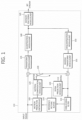
- FIG. 1 is a diagram schematically showing an example of a coder structure.
- a coder 100 of FIG. 1 may be a coder supporting high efficiency video coding.
- a coder 100 receives images and codes the received images by an intra mode or an inter mode to output a bitstream.
- a switch 130 is switched to an intra and when the coding is performed using the inter mode, the switch 130 is switched to an inter mode.
- a main flow of a coding process performed in the coder generates a prediction block for a block of the input images and then, obtains a difference between the block of the input images and the prediction block, thereby performing the coding.
- the generation of the prediction block is performed according to the intra mode and the inter mode.
- the prediction block is generated by allowing an intra prediction module 120 to perform spatial prediction by using already coded neighboring pixel values of the current block.
- a motion prediction module 105 searches a region that is optimally matched with the current input block in the reference picture stored in a reference picture buffer 110 to obtain a motion vector.
- a motion compensator 125 may perform motion compensation by using a motion vector to generate the prediction block.
- a subtractor 160 obtains the difference between the current block and the prediction block to generate a residual block.
- the coding for the residual block is performed in order such as transform in a transform module 135, quantization in a quantization module 140, entropy coding in an entropy encoding module 145 or the like.
- the transform module 135 receives the residual block to perform transform and outputs transform coefficients. Further, the quantizing module 140 quantizes the transform coefficients according to quantization parameters to output the quantized coefficients. Then, the entropy encoding module 145 performs the entropy coding on the quantized coefficients according to probability distribution and outputs the entropy coded coefficients as the bitstream.
- the currently coded images may be used as the reference picture of subsequently input images. Therefore, there is a need to decode and store the currently coded images.
- the quantized coefficients are dequantized and inversely transformed by passing through a dequantization module 150 and an inverse transform module 155.
- the residual block passing through the dequnatization and the inverse transform is resynthesized with the prediction image by an adder 165 to generate a reconstructed block.
- a deblocking filter 115 removes a blocking artifact of the reconstructed block generated during the coding process and the reference picture buffer 110 stores a deblocked reconstructed image.
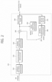
- FIG. 2 is a diagram schematically showing an example of a decoder structure.
- the decoder of FIG. 2 may be a decoder supporting high efficiency video coding.
- bitstream When performing the coding, the bitstream is output.
- a decoder 200 receives the bitstream and performs the received bitstream by the intra mode, thereby outputting the reconstructed images.
- a switch 240 In the case of the intra mode, a switch 240 is switched to the intra and in the case of the inter mode, the switch 240 is switched to the inter.
- a main flow of a decoding process performed in the decoder generates the prediction block and then, adds a result block of decoding the input bitstream and the prediction block, thereby generating a reconfigured block.
- the generation of the prediction block is performed according to the intra mode and the inter mode.
- an intra prediction module 250 performs the spatial prediction by using the already coded neighboring pixel values of the current block, thereby generating the prediction block.
- a motion compensation module 280 searches the corresponding region in the reference picture stored in a reference picture buffer 270 by using a motion vector to perform the motion compensation, thereby generating the prediction block.
- An entropy decoding module 210 performs the entropy decoding on the input bitstream according to the probability distribution and outputs the quantized coefficients.
- the quantized coefficients are dequantized and inversely transformed by passing through a dequnatization module 220 and an inverse transform module 230 and are then coupled with the prediction images by an adder 290, thereby generating the reconstructed block.
- the blocking artifact of the reconstructed block is removed by a deblocking filter 260 and then, the reconstructed block is stored in a reference picture buffer 270.
- the high efficiency video coding/decoding may process data using, for example, a coding unit (CU) unit for each predetermined unit.
- the CU may be referred to as a basic block unit processing data.
- FIG. 3 is a diagram explaining the CU, wherein FIG. 3 schematically explains one performing the split in the CU unit when processing data.
- the image is split in an already defined basic CU unit and is then subjected to the coding while splitting the CU.
- the most basic CU unit is referred to as a largest coding unit (LCU).
- LCU largest coding unit
- the CU may be split into four CUs of which the size of the block is reduced half in length and width if necessary Splitting the CU is determined according to the characteristics of the images at the coding side.
- the CU may be split into smaller CUs and in the case of the non-complex image, the CU may not be split into the smaller CUs. Therefore, whether the CU is split may be determined according to the efficiency in terms of the compression efficiency and the image quality.
- the information on whether to split the CU is represented by a split flag.
- the split flag is included in all the CUs other than the CU in the smallest unit that cannot be split any more.
- a split_flag of the split flag is '0'
- the corresponding CU is not split
- the split _flag of the split flag is '1'
- the corresponding CU is hierarchically split into four small CUs that are bisected in length and width, respectively.
- a depth is increased by 1 every time the CU is split once.
- the depth of the CUs having the same size may be the same.
- the maximum depth of the CU may be previously defined and the CU cannot be split at a predefined maximum depth or more. Therefore, the depth of split of the CU is increased by 1 while the CU is split from the LCU having a depth of 0 and the CU may not be split up to the maximum depth.
- the split _flag of the split flag when the split _flag of the split flag is 0 for the CU (LCTU) having depth 0, the CU is not split any more and when the split_flag of the split flag is 1, the CU may be split into four smaller CUs. In this case, the split small CUs may be differentiated by being allocated with indexes 0, 1, 2, and 3.
- FIG. 3 shows the case in which the maximum depth is set to be 4. As shown in FIG. 3 , when the CU is split up to the maximum depth 4, the CU is no further split.
- FIG. 4 is a diagram showing in more detail a process of splitting CU within LCU.
- the CUs 410, 420, and 430 of 32 ⁇ 32 pixels split in the CU of 64 ⁇ 64 pixels are no further split, '0' indicating the case in which the CU is not split as the split-flag of the split flag is stored.
- the CUs 410, 420, and 430 may be coded in a unit of 32 ⁇ 32 pixels using the intra mode or the inter mode.
- '1' is stored as the split-flag of the split flag regarding the CU 440 and the four CUs of 16 ⁇ 16 pixels is coded.
- the predetermined maximum depth is 3, if the CU of 16 ⁇ 16 pixels is set to the smallest CU (depth 2), the CU may not be split any more and therefore, may not include the split flag.
- the CU of 16 ⁇ 16 pixels is not set to be the smallest CU, the 16 ⁇ 16 pixels may be no further split. In this case, '0' is stored as the split flag.
- FIG. 5 is a diagram schematically explaining the split flag established when the split is performed like the example of FIG. 4 .
- the split flag regarding each CU is transmitted in the LCU unit
- the split flag regarding the CU of 64 ⁇ 64 pixels is first stored.
- the split flag regarding four CUs of 32 ⁇ 32 pixels subsequent to the split flag regarding the CU of 64 ⁇ 64 pixels is stored. Therefore, in the decoder, the split flag regarding the CU of 64 ⁇ 64 pixels is first confirmed and when the CU of 64 ⁇ 64 pixels is split, the split flag regarding the CU of 32 ⁇ 32 pixels may be confirmed.
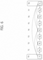
- FIG. 6 is a diagram schematically showing a hierarchical structure between frames applied when inter-picture prediction (inter prediction) is performed.
- inter prediction inter prediction
- all the CUs allocate the intra mode, that is, an intra frame (I-frame) within a frame for each predetermined frame and quickens an arbitrary access at the time of reproducing the image.
- FIG. 6 shows, by way of example, the case in which the inter-picture prediction is hierarchically performed by allocating 9 frames into one group.
- number 0 frame T0 is coded with the intra frame I0 and number 8 frame T8 is coded by performing the inter-picture prediction through the number 0 frame T0.
- the inter-picture prediction may be performed through the number 0 frame T0 and the number 8 frame T8 that are temporally previous and subsequent.
- the number 2 frame is hierarchically coded through the number 0 frame T0 and the number 4 fame T4 and number 6 frame T6 is coded through the number 4 frame T4 and the number 8 frame T8.
- the number 1 frame to the number 8 frame may be coded by determining the intra mode or the inter mode in the CU unit.
- the motion compensation is performed in the block unit.
- each block performs the motion compensation through forward prediction (L0 prediction) and inverse prediction (L1 prediction).
- the coding may be divided into the case in which the coding is performed by using only one of the L0 prediction and the L1 prediction and the coding is performed by using both of the L0 prediction and the LI prediction.
- the frame using only the L0 prediction in the frame unit is referred to as a P frame (prediction frame) and the frame using both of the L0 prediction and the L1 prediction is referred to as a B frame (Bi-prediction frame).
- the coding or the decoding is performed in the CU unit.
- most of the information is independently coded in the CU unit.
- the information on the CU (intra prediction direction information (IntraDir), split flag, skip information, motion merge information, coding mode information (Predic), block split flag (Part size), motion prediction information (AMVP), motion difference information (MVD), prediction direction information (Dir), or the like) accounts for a great part in the bitstream.
- the information on the CU is applied to the coding by determining whether the corresponding information has the high spatial correlation or the high temporal correlation.
- the coding and decoding may be performed in the CU unit.
- the coding may be performed by predicting the information on the corresponding CU through the information on the corresponding CU and the neighboring CU within the same frame when coding the CU.
- the coding may be performed by predicting the information on the corresponding CU through the information on the CU within the reference frame or the coding may be performed by predicting the information on the corresponding CU through the prediction structure in the frame unit.
- the compression efficiency for the information within the CU may be improved by using the information on the neighboring CU.
- the embodiment of the present invention proposes the method for predicting and coding/decoding the information on the current CU using the information on the neighboring CU upon coding/decoding the information on the CU.
- the neighboring CU to be used may also be the CU temporally neighboring to the current CU and the CU spatially neighboring to the current CU.
- the information on the neighboring CU to be used includes the information on the prediction structure in the frame unit to which the current CU and the CU neighboring to the current CU belong.
- the embodiment of the present invention discloses (1) the method for predicting and coding/decoding the information on the current CU through the information on the CU corresponding to the current CU within the reference frame (the coding method using the temporal correlation), (2) the method for predicting and coding/decoding the information on the current CU through the information on the CU neighboring to the current CU within the same frame (the coding method using the spatial correlation), and (3) the method for predicting and coding/decoding the information on the current CU through the prediction structure in the frame unit (the coding method using the prediction structure).
- the (1) to (3) methods select and apply the method appropriate for the information on the CU or the (1) to (3) methods may be adaptively applied.
- FIG. 7 is a diagram schematically explaining the correspondence relationship between the CU within the current frame and the CU of the reference frame.
- the information on the current CU 710 of a current frame 700 when the information on the current CU 710 of a current frame 700 is coded, the information on the CU 710 to be currently coded through the information on a CU 730 corresponding to the current CU 710 among the CUs of a reference frame 720 may be predicted and coded. Further, among the CUs of the reference frame 720, information variation of the current CU 710 for the information on the CU 730 corresponding to the current CU 710 may be coded.
- the information on the current CU is coded by using the information on the CU corresponding to the current CU within the reference frame, thereby improving the compression efficiency of the information on the CU.
- the reference frame which is an already coded frame before the current frame, means a frame used for temporal coding of the current frame.
- the CU may include the CU in the smallest unit from the LCU.
- the information on the CU to be predicted may include all the information within the CU.
- the information on the CU may include the CU, a prediction unit (PU), a transform unit (TU) split flag, information on the intra prediction or the inter prediction, mode information on the inter prediction on the merge skip, the merge, the motion vector prediction (MVP), or the like, a motion vector, a reference picture index, weighted prediction information, prediction mode information on the intra prediction, remaining mode information among the prediction mode information on the intra prediction, discrete cosine transform (DCT)/discrete sine transform (DST), information on a transform method of quantization parameter, or the like, information on an entropy coding method, or the like.
- DCT discrete cosine transform
- DST discrete sine transform
- the prediction flag (for example, the value of the prediction flag may be '0') indicating that the two information are not the same as each other is coded and transmitted (S840).
- the prediction flag (for example, the value of the prediction flag may be '0') indicating that the two information are not the same as each other is coded and transmitted (S840).
- various methods may be applied as the method for coding the information on the current CU.
- the method described in FIG. 8 may also be applied to the decoding process, in the same method as described above.
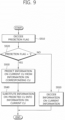
- FIG. 9 is a flow chart schematically explaining an example of a method for predicting and decoding the information of the current CU by using information on the neighboring CU in a system to which the embodiment of the present invention is applied.
- the method for predicting and decoding the information on the current CU by using the information on the CU corresponding to the current CU within the reference frame will be described.
- the decoder determines whether the value of the prediction flag is 1, that is, the prediction flag indicates that the information on the current CU is the same as the predicted information (S920).
- the value of the prediction flag is 1, the information on the current CU is predicted from the CU corresponding to the current CU within the reference frame (S930).
- the decoder generates the information on the CU predicted from the CU corresponding to the current CU within the reference frame and substitutes the information on the generated CU into the information on the current CU (S940). That is, the information on the predicted CU is used as the information on the current CU.
- the decoder decodes the information on the current CU without using the information on the neighboring CU (S950).
- various methods may be applied as the method for decoding the information on the current CU.
- the method for predicting and coding the split flag regarding the current LCU through the split flag regarding the LCU within the reference frame may be considered.
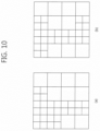
- FIG. 10 is a diagram for explaining the case of predicting the information on the current LCU through the information on the LCU corresponding to the current LCU within the reference frame.
- FIG. 10A shows the split flat of the LCU corresponding to the current LCU within the reference frame.
- FIG. 10B shows the split flag of the LCU of the current frame.
- Both of the LCUs of FIG. 10A and 10B show the split distribution of 64 ⁇ 64 pixels, by way of example. Referring to FIG. 10 , it can be confirmed that the split flag for the CU of the reference frame is similar to the split flag for the CU of the current frame.
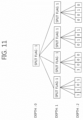
- FIG. 11 shows the split flag regarding the LCU shown in FIG. 10A .
- the split flag for the CU of the current frame is transferred at each CU level, regardless of the split structure of the reference frame.
- the split flag for the current frame can be predicted and coded by using the split structure of the reference frame in the embodiment of the present invention.
- the split distribution of the CU within the reference frame may be applied to the current CU and the split flag regarding the CU for a depth deeper than the current depth may not be transferred.
- '1' is stored as the split prediction information of the CU of 32 ⁇ 32 pixels at the lower left end and '0' is stored as the split prediction information of the CU of 32 ⁇ 32 pixels at the lower left end.
- FIG. 13 is a diagram schematically showing the current CU and the neighboring CU within the same frame.
- the CU may include the CU in the smallest unit from the LCU.
- the information on the CU may include all the information within the CU.
- the information on the CU may include the CU, a prediction unit (PU), a transform unit (TU) split flag, information on the intra prediction or the inter prediction, mode information on the inter prediction on the merge skip, the merge, the motion vector prediction (MVP), or the like, a motion vector, a reference picture index, weighted prediction information, prediction mode information on the intra prediction, remaining mode information among the prediction mode information on the intra prediction, discrete cosine transform (DCT)/discrete sine transform (DST), information on a transform method of quantization parameter, or the like, information on an entropy coding method, or the like.
- DCT discrete cosine transform
- DST discrete sine transform
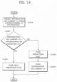
- the coder predicts the information on the current CU through the information on the already coded CU neighboring to the current CU to generate the prediction information (S 1410).
- the coder determines whether the information on the current CU is the same as the predicted CU information (S1420). When the information on the current CU is the same as the predicted CU information, the coder transfers the prediction flag '1' indicating that the information on the current CU is the same as the predicted CU (S1430). When the information on the current CU is not the same as the predicted CU information, the coder codes and transmits the prediction flag into the value of '0' (S1440) and at the same time, codes and transmits the information on the current CU (S1450).
- the information on the current CU may be coded by various methods as described below.
- the decoder determines whether the value of the prediction flag is 1, that is, the prediction flag indicates that the information on the current CU is the same as the predicted information (S1520).
- the value of the prediction flag is 1, the information on the current CU is predicted from the CU neighboring to the current CU (S1530).
- the decoder generates the information on the CU predicted from the CU neighboring to the current CU and substitutes the information on the generated CU into the information on the current CU (S1540). That is, the information on the predicted CU is used as the information on the current CU.
- the decoder decodes the information on the current CU without using the information on the neighboring CU (S1550).
- the prediction flag may be a flag indicating whether the current CU is coded by the intra prediction mode of the neighboring CU. Therefore, in this case, provided that the above-mentioned S1520 to 1550 are applied, the current CU may be predicted according to the intra prediction mode of the neighboring CU when the value of the decoded prediction flag is 1 and the current CU may be predicted according to another intra prediction mode, not the intra prediction mode of the neighboring CU, when the value of the decoded prediction flag is 0.
- FIG. 16 is a diagram explaining one predicting and coding the information on the current CU by using the neighboring CU.
- FIG. 16 shows the split distribution of two neighboring 64 ⁇ 64 LCUs 1610 and 1620. According to the embodiment of the present invention, it is possible to use the information on the LCU 1620 when the LCU 1610 is coded.
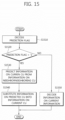
- FIG. 17 is a flow chart schematically explaining an example of a method for predicting and coding the information on the current CU from the prediction structure when coding the information on the current CU according to the embodiment of the present invention.
- the information on the current CU may be coded by various methods as described below.
- the decoder decodes the prediction flag so as to decode the information on the current CU (S1810).
- the prediction flag may be coded by the coder and may be transmitted as the bitstream.
- the decoder determines whether the value of the prediction flag is 1, that is, the prediction flag indicates that the information on the current CU is the same as the predicted information (S1820). When the value of the prediction flag is 1, the information on the current CU is predicted from the prediction structure (S1830). The decoder generates the information on the CU predicted from the prediction structure and substitutes the information on the generated CU into the information on the current CU (1840). That is, the information on the predicted CU is used as the information on the current CU.
- the information on the current CU may be decoded by various methods as described below.
- various methods may be applied as the method for decoding the information on the current CU.
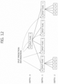
- FIG. 19 is a diagram explaining one predicting and coding the information on the current CU by the prediction structure in a frame unit according to the embodiment of the present invention when including a hierarchical prediction structure.
- all the CUs within the number 4 frame T4 designates L0 as the number 0 frame T0 and L1 as the number 8 frame T8. Since this has the hierarchical prediction structure in the frame unit, when the list is 1, the number 0 frame T0 or the number 8 frame T8 may be designated as the reference frame, respectively, but when the list is two, only the two reference frames are present. Therefore, the L0 designates the temporally previous frame as the reference frame and the L1 designates the temporally subsequent frame as the reference frame. In the case of the prediction structure shown in FIG.
- the compression efficiency for coding the reference index may be improved by transmitting the reference index of the corresponding list, together with the information that does not correspond to the case in which the prediction is performed by two lists by referring to the temporally previous frame and the temporally subsequent frame, respectively.
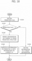
- the decoder determines whether the value of the reference index prediction flag represents 1 (S2020) and when the value of the reference index prediction flag is 1, the reference index is predicted through the prediction structure (S2030).
- the decoder designates the temporally previous frame and the temporally subsequent frame, respectively, as the reference index in the L0 and the L1 through the prediction structure (S2040).
- the decoder decodes the reference index corresponding to the list by the existing method (S2050).
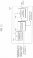
- a coder 2100 includes a CU information prediction module 2110, a determination module 2120, and a CU information coding module 2130.
- the CU information prediction module 2110 receives the information on the CU corresponding to the current CU within the reference frame to output the predicted CU information.
- the determination module 2120 receives the information on the current CU and the CU information predicted in the CU information prediction module 2110 to determine whether the information on the current CU is the same as the information on the predicted CU and transmits the prediction flag information according to the determination result.
- the transmitted prediction flag information is set to be '1'.
- the CU information coding module 2130 may code the information on the current CU by using the CU information predicted in the CU information prediction module 2110.
- the CU information coded in the CU information coding module 2130 is transmitted to the decoder, being included in the bitstream.
- FIG. 22 is a diagram showing a schematic configuration of a decoder for predicting and decoding the information on the current CU through the information on the CU corresponding to the current CU within the reference frame according to the embodiment of the present invention.
- the decoder 2200 includes a prediction flag decoding module 2210, a CU information prediction module 2220, and a CU information decoding module 2230.
- the prediction flag decoding module 2210 decodes the prediction flag information.
- the value predicted through the information on the CU corresponding to the current CU is stored as the information on the current CU within the reference frame.
- the CU information decoding module 2130 decodes the information on the coded CU transmitted within the bitstream and is stored as the information on the current CU. In this case, the CU information decoding module 2130 may decode the information on the current CU by using the CU information predicted in the CU information prediction module 2120.
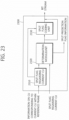
- FIG. 23 is a diagram showing another example of a coder for predicting and coding the information on the current CU through the information on the CU corresponding to the current CU within the reference frame according to the embodiment of the present invention.
- the coder predicts and codes the split flag regarding the current CU through the CU corresponding to the current CU within the reference frame.
- the CU split flag prediction module 2310 receives the split flag regarding the CU corresponding to the current CU within the reference frame to output the predicted CU split flag.
- the determination module 2320 receives the split flag regarding the current CU and the CU split flag predicted in the CU split flag prediction module 2310 to determine whether the split flag regarding the current CU is the same as the predicted CU split flag and transmits the split prediction flag information according to the determination result.
- the transmitted prediction flag information is set to be '1'.
- the split prediction information to be transmitted is set to be '0'.
- the CU split flag coding module 2330 may code the split flag regarding the current CU by using the CU split flag predicted in the CU split information prediction module 2310.
- the CU split flag decoded in the CU split flag decoding module 2330 is transmitted to the decoder, being included in the bitstream together with the prediction flag information.
- FIG. 24 is a diagram showing another example of a decoder for predicting and decoding the information on the current CU through the information on the CU corresponding to the current CU within the reference frame according to the embodiment of the present invention.
- the decoder predicts and decodes the split flag regarding the current CU through the CU corresponding to the current CU within the reference frame.
- the split prediction flag decoding module 2410 decodes the split prediction flag information.
- the CU split flag prediction module 2420 receives the split flag regarding the current CU through the information on the CU corresponding to the current CU within the reference frame.
- the value predicted through the information on the CU corresponding to the current CU is stored as the split flag regarding the current CU within the reference frame.
- the CU split flag decoding module 2430 decodes the split flag regarding the coded CU transmitted within the bitstream and is stored as the split flag regarding the current CU. In this case, the CU split flag decoding module 2430 may decode the split flag regarding the current CU by using the CU split flag predicted in the CU split flag prediction module 2420.
- FIG. 25 is a diagram schematically showing a configuration of the coder for predicting and coding the information on the current CU by using the information on the neighboring CU within the same frame according to the embodiment of the present invention.
- a coder 2500 includes a CU information prediction module 2510, a determination module 2520, and a CU information coding module 2530.
- the CU information prediction module 2510 receives the information on the CU neighboring to the current CU to output the predicted CU information.
- the determination module 2520 receives the information on the current CU and the CU information predicted in the CU information prediction module 2510 to determine whether the information on the current CU is the same as the information on the predicted CU and transmits the prediction flag information according to the determination result.
- the transmitted prediction flag information is set to be '1'.
- the prediction flag information is coded without separately coding the information on the current CU and is transmitted through the bitstream.
- the prediction flag information to be transmitted is set to be '0'.
- the CU information coding module 2530 may code the information on the current CU by using the CU information predicted in the CU information prediction module 2510.
- the CU information coded in the CU information coding module 2530 is transmitted to the decoder, being included in the bitstream together with the prediction flag information.
- FIG. 26 is a diagram schematically showing a configuration of the decoder for predicting and decoding the information on the current CU by using the information on the neighboring CU within the same frame according to the embodiment of the present invention.
- a decoder 2600 includes a prediction flag decoding module 2610, a CU information prediction module 2620, and a CU information decoding module 2630.
- the prediction flag decoding module 2610 decodes the prediction flag information.
- the CU information prediction module 2620 predicts the information on the current CU through the information on the CU neighboring to the current CU.
- the value predicted through the information on the CU neighboring to the current CU is stored as the information on the current CU.
- the CU information decoding module 2630 decodes the information on the coded CU transmitted within the bitstream and is stored as the information on the current CU. In this case, the CU information decoding module 2630 may decode the information on the current CU by using the CU information predicted in the CU information prediction module 2620.
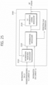
- FIG. 27 is a diagram schematically showing a configuration of the coder for predicting and decoding the information on the current CU through the prediction structure according to the embodiment of the present invention.
- the prediction flag information to be transmitted is set to be '0'.
- the CU information coding module 2730 may code the information on the current CU by using the CU information predicted in the CU information prediction module 2710.
- the CU information coded in the CU information coding module 2730 is transmitted to the decoder, being included in the bitstream together with the prediction flag information.
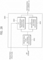
- the prediction flag decoding module 2810 decodes the prediction flag information.
- the CU information prediction module 2820 predicts the information on the current CU through the prediction structure.
- the prediction structure used for the prediction is as described in FIG. 6 and FIG. 19 .
- the information on the CU predicted through the prediction structure is stored as the information on the current CU.
Landscapes
- Engineering & Computer Science (AREA)
- Multimedia (AREA)
- Signal Processing (AREA)
- Computing Systems (AREA)
- Theoretical Computer Science (AREA)
- Compression Or Coding Systems Of Tv Signals (AREA)
Applications Claiming Priority (5)
| Application Number | Priority Date | Filing Date | Title |
|---|---|---|---|
| KR20100140721 | 2010-12-31 | ||
| PCT/KR2011/010379 WO2012091519A1 (ko) | 2010-12-31 | 2011-12-30 | 영상 정보 부호화 방법 및 복호화 방법과 이를 이용한 장치 |
| EP21215395.1A EP4033760B1 (de) | 2010-12-31 | 2011-12-30 | Verfahren zur kodierung von videoinformationen und verfahren zur decodierung von videoinformationen sowie vorrichtung damit |
| KR1020110147083A KR101831311B1 (ko) | 2010-12-31 | 2011-12-30 | 영상 정보 부호화 방법 및 복호화 방법과 이를 이용한 장치 |
| EP11852454.5A EP2661080A4 (de) | 2010-12-31 | 2011-12-30 | Verfahren zur kodierung von videoinformationen und verfahren zur decodierung von videoinformationen sowie vorrichtung damit |
Related Parent Applications (2)
| Application Number | Title | Priority Date | Filing Date |
|---|---|---|---|
| EP21215395.1A Division EP4033760B1 (de) | 2010-12-31 | 2011-12-30 | Verfahren zur kodierung von videoinformationen und verfahren zur decodierung von videoinformationen sowie vorrichtung damit |
| EP11852454.5A Division EP2661080A4 (de) | 2010-12-31 | 2011-12-30 | Verfahren zur kodierung von videoinformationen und verfahren zur decodierung von videoinformationen sowie vorrichtung damit |
Publications (4)
| Publication Number | Publication Date |
|---|---|
| EP4539464A2 true EP4539464A2 (de) | 2025-04-16 |
| EP4539464A3 EP4539464A3 (de) | 2025-06-11 |
| EP4539464B1 EP4539464B1 (de) | 2026-02-04 |
| EP4539464C0 EP4539464C0 (de) | 2026-02-04 |
Family
ID=46711929
Family Applications (4)
| Application Number | Title | Priority Date | Filing Date |
|---|---|---|---|
| EP25161198.4A Active EP4539464B1 (de) | 2010-12-31 | 2011-12-30 | Verfahren zur kodierung von videoinformationen und verfahren zur decodierung von videoinformationen sowie vorrichtung damit |
| EP11852454.5A Ceased EP2661080A4 (de) | 2010-12-31 | 2011-12-30 | Verfahren zur kodierung von videoinformationen und verfahren zur decodierung von videoinformationen sowie vorrichtung damit |
| EP25161199.2A Pending EP4539465A3 (de) | 2010-12-31 | 2011-12-30 | Verfahren zur kodierung von videoinformationen und verfahren zur decodierung von videoinformationen sowie vorrichtung damit |
| EP21215395.1A Active EP4033760B1 (de) | 2010-12-31 | 2011-12-30 | Verfahren zur kodierung von videoinformationen und verfahren zur decodierung von videoinformationen sowie vorrichtung damit |
Family Applications After (3)
| Application Number | Title | Priority Date | Filing Date |
|---|---|---|---|
| EP11852454.5A Ceased EP2661080A4 (de) | 2010-12-31 | 2011-12-30 | Verfahren zur kodierung von videoinformationen und verfahren zur decodierung von videoinformationen sowie vorrichtung damit |
| EP25161199.2A Pending EP4539465A3 (de) | 2010-12-31 | 2011-12-30 | Verfahren zur kodierung von videoinformationen und verfahren zur decodierung von videoinformationen sowie vorrichtung damit |
| EP21215395.1A Active EP4033760B1 (de) | 2010-12-31 | 2011-12-30 | Verfahren zur kodierung von videoinformationen und verfahren zur decodierung von videoinformationen sowie vorrichtung damit |
Country Status (15)
| Country | Link |
|---|---|
| US (9) | US9955155B2 (de) |
| EP (4) | EP4539464B1 (de) |
| KR (5) | KR101831311B1 (de) |
| DK (1) | DK4033760T3 (de) |
| ES (1) | ES3015557T3 (de) |
| FI (1) | FI4033760T3 (de) |
| HR (1) | HRP20250385T1 (de) |
| HU (1) | HUE070880T2 (de) |
| LT (1) | LT4033760T (de) |
| PL (1) | PL4033760T3 (de) |
| PT (1) | PT4033760T (de) |
| RS (1) | RS66634B1 (de) |
| SI (1) | SI4033760T1 (de) |
| SM (1) | SMT202500133T1 (de) |
| WO (1) | WO2012091519A1 (de) |
Families Citing this family (18)
| Publication number | Priority date | Publication date | Assignee | Title |
|---|---|---|---|---|
| EP4539464B1 (de) | 2010-12-31 | 2026-02-04 | Electronics And Telecommunications Research Institute | Verfahren zur kodierung von videoinformationen und verfahren zur decodierung von videoinformationen sowie vorrichtung damit |
| KR101210892B1 (ko) * | 2011-08-29 | 2012-12-11 | 주식회사 아이벡스피티홀딩스 | Amvp 모드에서의 예측 블록 생성 방법 |
| US11039138B1 (en) | 2012-03-08 | 2021-06-15 | Google Llc | Adaptive coding of prediction modes using probability distributions |
| WO2014038153A1 (ja) * | 2012-09-10 | 2014-03-13 | パナソニック株式会社 | 画像符号化方法、画像復号化方法、画像符号化装置、画像復号化装置、および、画像符号化復号化装置 |
| KR102352871B1 (ko) | 2012-09-28 | 2022-01-18 | 엘지전자 주식회사 | 영상 복호화 방법 및 이를 이용하는 장치 |
| KR102126855B1 (ko) * | 2013-02-15 | 2020-06-26 | 한국전자통신연구원 | 부호화 모드 결정 방법 및 장치 |
| US20140327737A1 (en) * | 2013-05-01 | 2014-11-06 | Raymond John Westwater | Method and Apparatus to Perform Optimal Visually-Weighed Quantization of Time-Varying Visual Sequences in Transform Space |
| US20150015782A1 (en) * | 2013-07-12 | 2015-01-15 | Vixs Systems, Inc. | Video processing device for reformatting an audio/video signal and methods for use therewith |
| JP6382329B2 (ja) * | 2014-02-18 | 2018-08-29 | エルジー エレクトロニクス インコーポレイティド | パノラマサービスのための放送信号送受信方法及び装置 |
| WO2016178485A1 (ko) * | 2015-05-05 | 2016-11-10 | 엘지전자 주식회사 | 영상 코딩 시스템에서 코딩 유닛 처리 방법 및 장치 |
| US9942548B2 (en) * | 2016-02-16 | 2018-04-10 | Google Llc | Entropy coding transform partitioning information |
| US10694187B2 (en) * | 2016-03-18 | 2020-06-23 | Lg Electronics Inc. | Method and device for deriving block structure in video coding system |
| CN109417629B (zh) * | 2016-07-12 | 2023-07-14 | 韩国电子通信研究院 | 图像编码/解码方法以及用于该方法的记录介质 |
| KR20180040827A (ko) | 2016-10-13 | 2018-04-23 | 디지털인사이트 주식회사 | 부호화 유닛의 그룹을 사용하는 비디오 코딩 방법 및 장치 |
| US10944974B2 (en) | 2017-01-11 | 2021-03-09 | Raytheon Company | Method for encoding and processing raw UHD video via an existing HD video architecture |
| US11190724B2 (en) | 2017-03-10 | 2021-11-30 | Raytheon Company | Adaptive bitrate streaming of UHD image data |
| CN110771169A (zh) | 2017-06-09 | 2020-02-07 | 韩国电子通信研究院 | 视频编码/解码方法和装置以及存储比特流的记录介质 |
| US11317090B2 (en) * | 2019-08-12 | 2022-04-26 | Tencent America LLC | Method and apparatus for video coding |
Family Cites Families (28)
| Publication number | Priority date | Publication date | Assignee | Title |
|---|---|---|---|---|
| EP1827027A1 (de) * | 2002-01-18 | 2007-08-29 | Kabushiki Kaisha Toshiba | Verfahren und Vorrichtung zur Videokodierung sowie Verfahren und Vorrichtung zur Videodekodierung |
| CN1312927C (zh) * | 2002-07-15 | 2007-04-25 | 株式会社日立制作所 | 动态图像编码方法及解码方法 |
| KR100865034B1 (ko) * | 2002-07-18 | 2008-10-23 | 엘지전자 주식회사 | 모션 벡터 예측 방법 |
| KR100506864B1 (ko) * | 2002-10-04 | 2005-08-05 | 엘지전자 주식회사 | 모션벡터 결정방법 |
| KR100529311B1 (ko) * | 2003-01-21 | 2005-11-17 | 삼성전자주식회사 | 신경 회로망을 이용하여 가변 길이 부호화 비트 스트림의길이를 선택하는 장치 및 방법 |
| KR100510136B1 (ko) * | 2003-04-28 | 2005-08-26 | 삼성전자주식회사 | 참조 픽처 결정 방법, 그 움직임 보상 방법 및 그 장치 |
| KR100727972B1 (ko) * | 2005-09-06 | 2007-06-14 | 삼성전자주식회사 | 영상의 인트라 예측 부호화, 복호화 방법 및 장치 |
| TWI344791B (en) * | 2006-07-12 | 2011-07-01 | Lg Electronics Inc | A method and apparatus for processing a signal |
| JP5151984B2 (ja) * | 2006-09-29 | 2013-02-27 | 富士通株式会社 | 動画像符号化装置 |
| KR101365567B1 (ko) | 2007-01-04 | 2014-02-20 | 삼성전자주식회사 | 영상의 예측 부호화 방법 및 장치, 그 복호화 방법 및 장치 |
| US8494046B2 (en) * | 2007-03-23 | 2013-07-23 | Lg Electronics Inc. | Method and an apparatus for decoding/encoding a video signal by performing illumination compensation |
| KR101366241B1 (ko) | 2007-03-28 | 2014-02-21 | 삼성전자주식회사 | 영상 부호화, 복호화 방법 및 장치 |
| CN101663899A (zh) * | 2007-04-26 | 2010-03-03 | 松下电器产业株式会社 | 运动检测装置、运动检测方法、以及运动检测程序 |
| US8265144B2 (en) * | 2007-06-30 | 2012-09-11 | Microsoft Corporation | Innovations in video decoder implementations |
| TWI338869B (en) * | 2007-08-03 | 2011-03-11 | Via Tech Inc | Method and apparatus for block-based digital encoded picture |
| WO2009051419A2 (en) * | 2007-10-16 | 2009-04-23 | Lg Electronics Inc. | A method and an apparatus for processing a video signal |
| US8897359B2 (en) * | 2008-06-03 | 2014-11-25 | Microsoft Corporation | Adaptive quantization for enhancement layer video coding |
| US8908763B2 (en) * | 2008-06-25 | 2014-12-09 | Qualcomm Incorporated | Fragmented reference in temporal compression for video coding |
| KR101306834B1 (ko) | 2008-09-22 | 2013-09-10 | 에스케이텔레콤 주식회사 | 인트라 예측 모드의 예측 가능성을 이용한 영상 부호화/복호화 장치 및 방법 |
| CN101742278B (zh) * | 2008-11-12 | 2012-11-07 | 富士通半导体股份有限公司 | 获取图像的运动矢量和边界强度的方法和系统 |
| KR101456498B1 (ko) * | 2009-08-14 | 2014-10-31 | 삼성전자주식회사 | 계층적 부호화 단위의 스캔 순서를 고려한 비디오 부호화 방법 및 장치, 비디오 복호화 방법 및 장치 |
| KR101510108B1 (ko) * | 2009-08-17 | 2015-04-10 | 삼성전자주식회사 | 영상의 부호화 방법 및 장치, 그 복호화 방법 및 장치 |
| KR101452860B1 (ko) * | 2009-08-17 | 2014-10-23 | 삼성전자주식회사 | 영상의 부호화 방법 및 장치, 영상 복호화 방법 및 장치 |
| KR101752418B1 (ko) * | 2010-04-09 | 2017-06-29 | 엘지전자 주식회사 | 비디오 신호 처리 방법 및 장치 |
| US8837592B2 (en) * | 2010-04-14 | 2014-09-16 | Mediatek Inc. | Method for performing local motion vector derivation during video coding of a coding unit, and associated apparatus |
| US20110310976A1 (en) * | 2010-06-17 | 2011-12-22 | Qualcomm Incorporated | Joint Coding of Partition Information in Video Coding |
| EP4539464B1 (de) | 2010-12-31 | 2026-02-04 | Electronics And Telecommunications Research Institute | Verfahren zur kodierung von videoinformationen und verfahren zur decodierung von videoinformationen sowie vorrichtung damit |
| KR102404121B1 (ko) * | 2011-07-11 | 2022-05-31 | 선 페이턴트 트러스트 | 화상 복호 방법, 화상 부호화 방법, 화상 복호 장치, 화상 부호화 장치 및 화상 부호화 복호 장치 |
-
2011
- 2011-12-30 EP EP25161198.4A patent/EP4539464B1/de active Active
- 2011-12-30 PL PL21215395.1T patent/PL4033760T3/pl unknown
- 2011-12-30 EP EP11852454.5A patent/EP2661080A4/de not_active Ceased
- 2011-12-30 RS RS20250317A patent/RS66634B1/sr unknown
- 2011-12-30 WO PCT/KR2011/010379 patent/WO2012091519A1/ko not_active Ceased
- 2011-12-30 KR KR1020110147083A patent/KR101831311B1/ko active Active
- 2011-12-30 PT PT212153951T patent/PT4033760T/pt unknown
- 2011-12-30 EP EP25161199.2A patent/EP4539465A3/de active Pending
- 2011-12-30 HR HRP20250385TT patent/HRP20250385T1/hr unknown
- 2011-12-30 FI FIEP21215395.1T patent/FI4033760T3/fi active
- 2011-12-30 LT LTEP21215395.1T patent/LT4033760T/lt unknown
- 2011-12-30 EP EP21215395.1A patent/EP4033760B1/de active Active
- 2011-12-30 SM SM20250133T patent/SMT202500133T1/it unknown
- 2011-12-30 US US13/977,520 patent/US9955155B2/en active Active
- 2011-12-30 HU HUE21215395A patent/HUE070880T2/hu unknown
- 2011-12-30 ES ES21215395T patent/ES3015557T3/es active Active
- 2011-12-30 SI SI201132131T patent/SI4033760T1/sl unknown
- 2011-12-30 DK DK21215395.1T patent/DK4033760T3/da active
-
2013
- 2013-10-02 US US14/044,542 patent/US11064191B2/en active Active
-
2018
- 2018-02-13 US US15/894,973 patent/US11025901B2/en active Active
- 2018-02-14 KR KR1020180018488A patent/KR101969051B1/ko active Active
- 2018-02-14 KR KR1020180018486A patent/KR101920352B1/ko active Active
- 2018-02-14 KR KR1020180018489A patent/KR101920354B1/ko active Active
- 2018-02-14 KR KR1020180018487A patent/KR101920353B1/ko active Active
- 2018-02-15 US US15/897,440 patent/US11102471B2/en active Active
- 2018-02-15 US US15/897,512 patent/US11082686B2/en active Active
-
2021
- 2021-06-10 US US17/344,161 patent/US11388393B2/en active Active
-
2022
- 2022-02-01 US US17/590,161 patent/US11889052B2/en active Active
-
2023
- 2023-12-06 US US18/530,617 patent/US12513284B2/en active Active
-
2025
- 2025-11-06 US US19/381,588 patent/US20260067447A1/en active Pending
Also Published As
Similar Documents
| Publication | Publication Date | Title |
|---|---|---|
| US11889052B2 (en) | Method for encoding video information and method for decoding video information, and apparatus using same | |
| KR101962183B1 (ko) | 인트라 예측 모드 부호화/복호화 방법 및 장치 | |
| JP6518274B2 (ja) | 映像復号化方法および映像符号化方法 | |
| HK40077933A (en) | Method for encoding video information and method for decoding video information, and apparatus using same | |
| HK40077933B (en) | Method for encoding video information and method for decoding video information, and apparatus using same |
Legal Events
| Date | Code | Title | Description |
|---|---|---|---|
| PUAI | Public reference made under article 153(3) epc to a published international application that has entered the european phase |
Free format text: ORIGINAL CODE: 0009012 |
|
| STAA | Information on the status of an ep patent application or granted ep patent |
Free format text: STATUS: REQUEST FOR EXAMINATION WAS MADE |
|
| 17P | Request for examination filed |
Effective date: 20250303 |
|
| AC | Divisional application: reference to earlier application |
Ref document number: 2661080 Country of ref document: EP Kind code of ref document: P Ref document number: 4033760 Country of ref document: EP Kind code of ref document: P |
|
| AK | Designated contracting states |
Kind code of ref document: A2 Designated state(s): AL AT BE BG CH CY CZ DE DK EE ES FI FR GB GR HR HU IE IS IT LI LT LU LV MC MK MT NL NO PL PT RO RS SE SI SK SM TR |
|
| REG | Reference to a national code |
Ref country code: DE Ref legal event code: R079 Free format text: PREVIOUS MAIN CLASS: H04N0019610000 Ipc: H04N0019105000 Ref country code: DE Ref legal event code: R079 Ref document number: 602011075603 Country of ref document: DE Free format text: PREVIOUS MAIN CLASS: H04N0019610000 Ipc: H04N0019105000 |
|
| PUAL | Search report despatched |
Free format text: ORIGINAL CODE: 0009013 |
|
| STAA | Information on the status of an ep patent application or granted ep patent |
Free format text: STATUS: EXAMINATION IS IN PROGRESS |
|
| AK | Designated contracting states |
Kind code of ref document: A3 Designated state(s): AL AT BE BG CH CY CZ DE DK EE ES FI FR GB GR HR HU IE IS IT LI LT LU LV MC MK MT NL NO PL PT RO RS SE SI SK SM TR |
|
| RIC1 | Information provided on ipc code assigned before grant |
Ipc: H04N 19/61 20140101ALI20250502BHEP Ipc: H04N 19/196 20140101ALI20250502BHEP Ipc: H04N 19/105 20140101AFI20250502BHEP |
|
| 17Q | First examination report despatched |
Effective date: 20250521 |
|
| GRAP | Despatch of communication of intention to grant a patent |
Free format text: ORIGINAL CODE: EPIDOSNIGR1 |
|
| STAA | Information on the status of an ep patent application or granted ep patent |
Free format text: STATUS: GRANT OF PATENT IS INTENDED |
|
| RIC1 | Information provided on ipc code assigned before grant |
Ipc: H04N 19/105 20140101AFI20250811BHEP Ipc: H04N 19/196 20140101ALI20250811BHEP Ipc: H04N 19/61 20140101ALI20250811BHEP Ipc: H04N 19/136 20140101ALI20250811BHEP |
|
| INTG | Intention to grant announced |
Effective date: 20250911 |
|
| GRAS | Grant fee paid |
Free format text: ORIGINAL CODE: EPIDOSNIGR3 |
|
| GRAA | (expected) grant |
Free format text: ORIGINAL CODE: 0009210 |
|
| STAA | Information on the status of an ep patent application or granted ep patent |
Free format text: STATUS: THE PATENT HAS BEEN GRANTED |
|
| AC | Divisional application: reference to earlier application |
Ref document number: 4033760 Country of ref document: EP Kind code of ref document: P Ref document number: 2661080 Country of ref document: EP Kind code of ref document: P |
|
| AK | Designated contracting states |
Kind code of ref document: B1 Designated state(s): AL AT BE BG CH CY CZ DE DK EE ES FI FR GB GR HR HU IE IS IT LI LT LU LV MC MK MT NL NO PL PT RO RS SE SI SK SM TR |
|
| REG | Reference to a national code |
Ref country code: CH Ref legal event code: F10 Free format text: ST27 STATUS EVENT CODE: U-0-0-F10-F00 (AS PROVIDED BY THE NATIONAL OFFICE) Effective date: 20260204 Ref country code: GB Ref legal event code: FG4D |
|
| REG | Reference to a national code |
Ref country code: IE Ref legal event code: FG4D |
|
| REG | Reference to a national code |
Ref country code: DE Ref legal event code: R096 Ref document number: 602011075603 Country of ref document: DE |