EP4539308A1 - Unit - Google Patents
Unit Download PDFInfo
- Publication number
- EP4539308A1 EP4539308A1 EP23823578.2A EP23823578A EP4539308A1 EP 4539308 A1 EP4539308 A1 EP 4539308A1 EP 23823578 A EP23823578 A EP 23823578A EP 4539308 A1 EP4539308 A1 EP 4539308A1
- Authority
- EP
- European Patent Office
- Prior art keywords
- gear
- electrical machine
- rotating electrical
- unit
- shaft
- Prior art date
- Legal status (The legal status is an assumption and is not a legal conclusion. Google has not performed a legal analysis and makes no representation as to the accuracy of the status listed.)
- Pending
Links
Images


Classifications
-
- H—ELECTRICITY
- H02—GENERATION; CONVERSION OR DISTRIBUTION OF ELECTRIC POWER
- H02K—DYNAMO-ELECTRIC MACHINES
- H02K7/00—Arrangements for handling mechanical energy structurally associated with dynamo-electric machines, e.g. structural association with mechanical driving motors or auxiliary dynamo-electric machines
- H02K7/10—Structural association with clutches, brakes, gears, pulleys or mechanical starters
- H02K7/116—Structural association with clutches, brakes, gears, pulleys or mechanical starters with gears
-
- B—PERFORMING OPERATIONS; TRANSPORTING
- B60—VEHICLES IN GENERAL
- B60K—ARRANGEMENT OR MOUNTING OF PROPULSION UNITS OR OF TRANSMISSIONS IN VEHICLES; ARRANGEMENT OR MOUNTING OF PLURAL DIVERSE PRIME-MOVERS IN VEHICLES; AUXILIARY DRIVES FOR VEHICLES; INSTRUMENTATION OR DASHBOARDS FOR VEHICLES; ARRANGEMENTS IN CONNECTION WITH COOLING, AIR INTAKE, GAS EXHAUST OR FUEL SUPPLY OF PROPULSION UNITS IN VEHICLES
- B60K1/00—Arrangement or mounting of electrical propulsion units
-
- B—PERFORMING OPERATIONS; TRANSPORTING
- B60—VEHICLES IN GENERAL
- B60K—ARRANGEMENT OR MOUNTING OF PROPULSION UNITS OR OF TRANSMISSIONS IN VEHICLES; ARRANGEMENT OR MOUNTING OF PLURAL DIVERSE PRIME-MOVERS IN VEHICLES; AUXILIARY DRIVES FOR VEHICLES; INSTRUMENTATION OR DASHBOARDS FOR VEHICLES; ARRANGEMENTS IN CONNECTION WITH COOLING, AIR INTAKE, GAS EXHAUST OR FUEL SUPPLY OF PROPULSION UNITS IN VEHICLES
- B60K17/00—Arrangement or mounting of transmissions in vehicles
- B60K17/04—Arrangement or mounting of transmissions in vehicles characterised by arrangement, location or kind of gearing
- B60K17/16—Arrangement or mounting of transmissions in vehicles characterised by arrangement, location or kind of gearing of differential gearing
- B60K17/165—Arrangement or mounting of transmissions in vehicles characterised by arrangement, location or kind of gearing of differential gearing provided between independent half axles
-
- B—PERFORMING OPERATIONS; TRANSPORTING
- B60—VEHICLES IN GENERAL
- B60L—PROPULSION OF ELECTRICALLY-PROPELLED VEHICLES; SUPPLYING ELECTRIC POWER FOR AUXILIARY EQUIPMENT OF ELECTRICALLY-PROPELLED VEHICLES; ELECTRODYNAMIC BRAKE SYSTEMS FOR VEHICLES IN GENERAL; MAGNETIC SUSPENSION OR LEVITATION FOR VEHICLES; MONITORING OPERATING VARIABLES OF ELECTRICALLY-PROPELLED VEHICLES; ELECTRIC SAFETY DEVICES FOR ELECTRICALLY-PROPELLED VEHICLES
- B60L15/00—Methods, circuits, or devices for controlling the traction-motor speed of electrically-propelled vehicles
- B60L15/007—Physical arrangements or structures of drive train converters specially adapted for the propulsion motors of electric vehicles
-
- F—MECHANICAL ENGINEERING; LIGHTING; HEATING; WEAPONS; BLASTING
- F16—ENGINEERING ELEMENTS AND UNITS; GENERAL MEASURES FOR PRODUCING AND MAINTAINING EFFECTIVE FUNCTIONING OF MACHINES OR INSTALLATIONS; THERMAL INSULATION IN GENERAL
- F16H—GEARING
- F16H37/00—Combinations of mechanical gearings, not provided for in groups F16H1/00 - F16H35/00
- F16H37/02—Combinations of mechanical gearings, not provided for in groups F16H1/00 - F16H35/00 comprising essentially only toothed or friction gearings
- F16H37/06—Combinations of mechanical gearings, not provided for in groups F16H1/00 - F16H35/00 comprising essentially only toothed or friction gearings with a plurality of driving or driven shafts; with arrangements for dividing torque between two or more intermediate shafts
- F16H37/08—Combinations of mechanical gearings, not provided for in groups F16H1/00 - F16H35/00 comprising essentially only toothed or friction gearings with a plurality of driving or driven shafts; with arrangements for dividing torque between two or more intermediate shafts with differential gearing
- F16H37/0806—Combinations of mechanical gearings, not provided for in groups F16H1/00 - F16H35/00 comprising essentially only toothed or friction gearings with a plurality of driving or driven shafts; with arrangements for dividing torque between two or more intermediate shafts with differential gearing with a plurality of driving or driven shafts
- F16H37/0813—Combinations of mechanical gearings, not provided for in groups F16H1/00 - F16H35/00 comprising essentially only toothed or friction gearings with a plurality of driving or driven shafts; with arrangements for dividing torque between two or more intermediate shafts with differential gearing with a plurality of driving or driven shafts with only one input shaft
-
- H—ELECTRICITY
- H02—GENERATION; CONVERSION OR DISTRIBUTION OF ELECTRIC POWER
- H02K—DYNAMO-ELECTRIC MACHINES
- H02K11/00—Structural association of dynamo-electric machines with electric components or with devices for shielding, monitoring or protection
- H02K11/30—Structural association with control circuits or drive circuits
-
- H—ELECTRICITY
- H02—GENERATION; CONVERSION OR DISTRIBUTION OF ELECTRIC POWER
- H02K—DYNAMO-ELECTRIC MACHINES
- H02K5/00—Casings; Enclosures; Supports
- H02K5/04—Casings or enclosures characterised by the shape, form or construction thereof
- H02K5/15—Mounting arrangements for bearing-shields or end plates
-
- H—ELECTRICITY
- H02—GENERATION; CONVERSION OR DISTRIBUTION OF ELECTRIC POWER
- H02K—DYNAMO-ELECTRIC MACHINES
- H02K5/00—Casings; Enclosures; Supports
- H02K5/04—Casings or enclosures characterised by the shape, form or construction thereof
- H02K5/16—Means for supporting bearings, e.g. insulating supports or means for fitting bearings in the bearing-shields
- H02K5/173—Means for supporting bearings, e.g. insulating supports or means for fitting bearings in the bearing-shields using bearings with rolling contact, e.g. ball bearings
- H02K5/1732—Means for supporting bearings, e.g. insulating supports or means for fitting bearings in the bearing-shields using bearings with rolling contact, e.g. ball bearings radially supporting the rotary shaft at both ends of the rotor
-
- B—PERFORMING OPERATIONS; TRANSPORTING
- B60—VEHICLES IN GENERAL
- B60K—ARRANGEMENT OR MOUNTING OF PROPULSION UNITS OR OF TRANSMISSIONS IN VEHICLES; ARRANGEMENT OR MOUNTING OF PLURAL DIVERSE PRIME-MOVERS IN VEHICLES; AUXILIARY DRIVES FOR VEHICLES; INSTRUMENTATION OR DASHBOARDS FOR VEHICLES; ARRANGEMENTS IN CONNECTION WITH COOLING, AIR INTAKE, GAS EXHAUST OR FUEL SUPPLY OF PROPULSION UNITS IN VEHICLES
- B60K1/00—Arrangement or mounting of electrical propulsion units
- B60K2001/001—Arrangement or mounting of electrical propulsion units one motor mounted on a propulsion axle for rotating right and left wheels of this axle
-
- F—MECHANICAL ENGINEERING; LIGHTING; HEATING; WEAPONS; BLASTING
- F16—ENGINEERING ELEMENTS AND UNITS; GENERAL MEASURES FOR PRODUCING AND MAINTAINING EFFECTIVE FUNCTIONING OF MACHINES OR INSTALLATIONS; THERMAL INSULATION IN GENERAL
- F16H—GEARING
- F16H1/00—Toothed gearings for conveying rotary motion
- F16H1/02—Toothed gearings for conveying rotary motion without gears having orbital motion
- F16H1/20—Toothed gearings for conveying rotary motion without gears having orbital motion involving more than two intermeshing members
-
- F—MECHANICAL ENGINEERING; LIGHTING; HEATING; WEAPONS; BLASTING
- F16—ENGINEERING ELEMENTS AND UNITS; GENERAL MEASURES FOR PRODUCING AND MAINTAINING EFFECTIVE FUNCTIONING OF MACHINES OR INSTALLATIONS; THERMAL INSULATION IN GENERAL
- F16H—GEARING
- F16H48/00—Differential gearings
- F16H48/06—Differential gearings with gears having orbital motion
- F16H48/08—Differential gearings with gears having orbital motion comprising bevel gears
Definitions
- the present invention relates to a unit.
- Patent Document 1 discloses a vehicle drive device including a counter gear mechanism that reduces a speed.
- the vehicle drive device transmits output torque of a rotating electrical machine to a pair of wheels via a pair of output members to run a vehicle.
- Patent Document 1 WO2021/131204
- the rotating electrical machine can be used in combination with a power transmission mechanism such as a reduction mechanism, an acceleration mechanism, and a transmission mechanism.
- a power transmission mechanism such as a reduction mechanism, an acceleration mechanism, and a transmission mechanism.
- the present invention has been made in consideration of such a problem, and an object thereof is to improve the layout property of the unit.
- a unit includes: a rotating electrical machine; an inverter located in an outer periphery of the rotating electrical machine; a first gear connected downstream of the rotating electrical machine; a second gear to mesh with the first gear; a third gear connected downstream of the second gear via a shaft; and a fourth gear to mesh with the third gear.
- the shaft has a portion that overlaps a stator of the rotating electrical machine when viewed in a radial direction
- the inverter has a portion that overlaps the second gear when viewed in an axial direction.
- the second gear and the third gear are separated with respect to a shaft that passes through the outer periphery (outer peripheral space) of a main body of the rotating electrical machine. That is, the second gear and the third gear are separated by the shaft that extends to pass through the outer periphery of the main body of the rotating electrical machine. Accordingly, the interference between the second gear and a fourth gear or a component connected to the fourth gear (for example, a differential gear) can be avoided, and a dimension in the axial direction can be reduced, and further, the inverter is caused to overlap the second gear, that is, the inverter is disposed close to the shaft to overlap the second gear, which can contribute to reduce the unit in size. Therefore, a layout property of the unit can be improved.
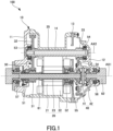
- FIG. 1 is a schematic configuration diagram of a unit 100 according to the present embodiment.
- a unit can also be referred to as, for example, a motor unit (a unit including at least a motor) or a power transmission device (a device including at least a power transmission mechanism).
- the motor is a rotating electrical machine having an electric motor function and/or a generator function (at least one of the electric motor function and the generator function).
- the power transmission mechanism is, for example, a gear mechanism and/or a differential gear mechanism.
- the device (unit) including the motor and the power transmission mechanism is included in concepts of both the motor unit and the power transmission device.
- the unit 100 includes a housing 10, a rotating electrical machine 20, a reduction mechanism 30, and a differential gear 40.
- the unit 100 is mounted on an electric vehicle, and the vehicle is an electric vehicle.
- the housing 10 includes a first cover 11, a second cover 12, a plate 13, and a case 14.
- the rotating electrical machine 20, the reduction mechanism 30, and the differential gear 40 are accommodated in the housing 10.
- the first cover 11 closes an opening of the cylindrical case 14 from one side in an axial direction (left side in FIG. 1 )
- the second cover 12 closes an opening of the case 14 from the other side in the axial direction via the plate 13.
- the rotating electrical machine 20 is provided in the case 14.
- the rotating electrical machine 20 is provided with one side in the axial direction as an output side.
- the rotating electrical machine 20 includes a rotor 21, a stator 22, and a rotation shaft 23, and constitutes a drive source of the vehicle.
- the rotor 21 is provided on an outer periphery of the rotation shaft 23.
- the stator 22 is provided in the case 14 and accommodates the rotor 21.
- the rotation shaft 23 protrudes from the rotor 21 toward both sides in the axial direction, and is supported by a bearing 51 provided on the first cover 11 and a bearing 52 provided on the plate 13.
- the rotation shaft 23 has a hollow structure.
- a first drive shaft 61 passes through the rotation shaft 23 from one side in the axial direction.
- the first drive shaft 61 further passes through the plate 13 and is assembled to the differential gear 40.
- a bearing holding holes is formed in a portion of the plate 13 through which the first drive shaft 61 passes.
- the bearing 52 is provided from one end side in the axial direction, and the bearing 55 is provided from the other end side in the axial direction.
- the reduction mechanism 30 is a gear mechanism and includes a first gear 31, a second gear 32, a third gear 33, a fourth gear 34, and a long shaft 35.
- the first gear 31 and the fourth gear 34 are disposed on a first axis AX1 together with the rotating electrical machine 20.
- the rotating electrical machine 20, the first gear 31, and the fourth gear 34 are disposed coaxially with respect to the first axis AX1.
- a plurality of elements (components, portions, and the like) being disposed on an N-th axis (N is a natural number) is synonymous with the plurality of elements being disposed coaxially with respect to the N-th axis.
- the second gear 32 and the third gear 33 are disposed on a second axis AX2.
- Both the first axis AX1 and the second axis AX2 constitute axes of the unit 100 and extend along the same direction. Therefore, extension directions of the first axis AX1 and the second axis AX2 both correspond to the axial direction of the unit 100. That is, the axial direction means an axial direction of the rotation shaft of a component (for example, the motor, the gear mechanism, and the differential gear mechanism) that constitutes the unit.
- a radial direction of the unit 100 is a direction orthogonal to the first axis AX1 or the second axis AX2.
- the first axis AX1 constitutes an axis of the rotation shaft 23 and the differential gear 40
- the second axis AX2 constitutes an axis of the long shaft 35.
- the first gear 31 is connected downstream of the rotating electrical machine 20.
- the downstream is a power output side, and the rotor 21 and the stator 22 that generate power are used as references for the downstream of the rotating electrical machine 20. Therefore, the downstream of the rotating electrical machine 20 can be said to be the downstream of the stator 22.
- the rotation shaft 23 does not need to be understood as a component of the rotating electrical machine 20 in terms of positional relation in power transmission.
- the downstream is the power output side, whereas the upstream is a power input side.
- the first gear 31 is connected downstream of the rotating electrical machine 20 to be capable of transmitting power.
- the connection may be made via other configurations (for example, a clutch or other gear mechanisms).
- the first gear 31 is provided closer to one side in the axial direction than the rotor 21, and is provided on a portion of the rotation shaft 23 between the rotor 21 and the bearing 51.
- the first gear 31 is integrally formed with the rotation shaft 23.
- the second gear 32 meshes with the first gear 31.
- the second gear 32 includes a larger number of teeth than the first gear 31, and constitutes a first reduction gear stage together with the first gear 31.
- the second gear 32 is provided on the long shaft 35.
- the second gear 32 is integrated with the long shaft 35 by being press-fitted to the long shaft 35.
- the long shaft 35 extends along the rotation shaft 23 and passes through an outer periphery (outer peripheral space) of the stator 22.
- the long shaft 35 has a portion that overlaps the stator 22 when viewed in the radial direction.
- this portion overlaps the stator 22 when viewed in the radial direction along a plane including the first axis AX1 and the second axis AX2.
- the expression "overlapping when viewed in a predetermined direction including a radial direction and an axial direction" means overlapping in the predetermined direction, and means that a plurality of elements are aligned in the predetermined direction. Therefore, when a drawing illustrates that a plurality of elements are aligned in a predetermined direction, it may be assumed that the specification contains a sentence explaining that the plurality of elements overlap when viewed in the predetermined direction.
- the long shaft 35 extends through the plate 13 to the other end side in the axial direction further than the stator 22.
- An insertion hole for the long shaft 35 is provided in a portion of the plate 13 through which the long shaft 35 passes.
- the long shaft 35 is supported by a bearing 53 provided on the first cover 11 and a bearing 54 provided on the second cover 12.
- the third gear 33 is provided on the long shaft 35.
- the long shaft 35 is located downstream of the second gear 32, and the third gear 33 is connected downstream of the second gear 32 via the long shaft 35.
- the third gear 33 is connected downstream of the second gear 32 via a part of the long shaft 35.
- the third gear 33 is provided on a portion of the long shaft 35 extending to the other side in the axial direction further than the stator 22. This portion is a portion closer to the other end side in the axial direction than the plate 13.
- the third gear 33 is provided on a portion between the stator 22 and the bearing 54, and is integrally formed with the long shaft 35.
- the second gear 32 is provided on one end side in the axial direction, and the third gear 33 is provided on the other end side in the axial direction. That is, the second gear 32 and the third gear 33 are disposed at two ends with respect to the long shaft 35, and are separated by the long shaft 35 that extends to pass through the outer periphery of the stator 22. Accordingly, interference between the second gear 32 and the fourth gear 34 or the differential gear 40 that is an example of a component connected to the fourth gear 34 can be avoided, and a dimension of the unit 100 in the axial direction can be reduced.
- the dimension in the axial direction can be reduced, for example, as compared with a case where the first gear 31 to the fourth gear 34 are collectively disposed on one side in the axial direction with respect to the stator 22.
- the second gear 32 and the third gear 33 are provided between the bearing 53 and the bearing 54 in the axial direction.
- the fourth gear 34 meshes with the third gear 33.
- the fourth gear 34 is a final gear and is provided on the differential gear 40.
- the power from the rotating electrical machine 20 is transmitted from the fourth gear 34 to the differential gear 40. Therefore, the differential gear 40 is connected downstream of the fourth gear 34.
- the fourth gear 34 includes a larger number of teeth than the third gear 33, and constitutes a second reduction gear stage together with the third gear 33. Therefore, in the reduction mechanism 30, a two-stage reduction is performed by the first gear 31 and the second gear 32, and the third gear 33 and the fourth gear 34. Accordingly, in order to ensure a reduction ratio, a diameter of a reduction gear can be reduced as compared with one-stage reduction. As a result, a constraint on a layout, such as a limitation on making the unit 100 compact, which is caused by the necessity to ensure an inter-axis distance corresponding to a large diameter of the reduction gear, are alleviated.
- the differential gear 40 is the differential gear mechanism and is disposed on the first axis AX1.
- the differential gear 40 includes a differential case 41 and a differential unit 42.
- the differential case 41 is supported by the bearing 55 provided on the plate 13 and a bearing 56 provided on the second cover 12, and rotates together with the fourth gear 34.
- the fourth gear 34 is coaxially fixed to an outer wall portion of the differential case 41, and the differential case 41 accommodates the differential unit 42.
- the differential unit 42 distributes and outputs, to drive wheels in a left-right direction of the vehicle, the power input to the differential case 41 via the fourth gear 34.
- the differential gear 40 protrudes in a direction away from the stator 22 with respect to the fourth gear 34.
- the differential gear 40 protrudes to have a portion, serving as a protruding portion, which protrudes more in the axial direction from the fourth gear 34.
- the differential gear 40 protrudes more in the direction away from the stator 22 than in a direction close to the stator 22 with respect to the fourth gear 34, and is disposed in the direction away from the stator 22 with respect to the fourth gear 34.
- the fourth gear 34 can be disposed closer to the stator 22 than in the case where the differential gear 40 protrudes in an opposite direction, the long shaft 35 is prevented from becoming longer.
- an influence of torsion of the long shaft 35 is reduced regarding a fact that the influence of the torsion increases as the long shaft 35 becomes longer.
- an increase in the dimension in the axial direction of the unit 100 is also prevented.
- the bearing 54 serving as a bearing that supports the long shaft 35 overlaps the differential gear 40 when viewed in the radial direction (for example, viewed in the radial direction along the plane including the first axis AX1 and the second axis AX2). Therefore, the dimension in the axial direction of the unit 100 on a straight line passing through the second axis AX2 can also be reduced.
- a first drive shaft 61 is attached from the one side in the axial direction, and a second drive shaft 62 is attached from the other side in the axial direction.
- the power from the rotating electrical machine 20 is transmitted, from the differential unit 42, to one drive wheel via the first drive shaft 61 and to the other drive wheel via the second drive shaft 62.
- the first drive shaft 61 is longer than the second drive shaft 62, so that a distance between the drive wheel and the differential gear 40 increases, thereby limiting a bending angle.
- the first drive shaft 61 is supported by a bearing 57 provided on the first cover 11.
- the fourth gear 34 may also be understood as a part of the differential gear 40. That is, the fourth gear 34 may also be understood as one component of the differential gear 40. Also in this case, it can be understood that the differential gear 40 including the differential unit 42 that outputs the power from the rotating electrical machine 20 is connected downstream of the fourth gear 34 in such a manner that a part of the differential gear 40 is connected downstream of the fourth gear 34.
- FIGS. 2 and 3 are each a diagram illustrating an arrangement of the inverter 70.
- FIG. 2 illustrates an external appearance of the unit 100 when viewed in the radial direction in a state where the housing 10 is omitted.
- FIG. 3 illustrates an arrangement of a main configuration necessary for the description when viewed in the axial direction (when viewed from the right side in FIG. 2 ).
- the unit 100 further includes the inverter 70.
- the inverter 70 may be provided outside the housing 10.
- the inverter 70 may be accommodated in the housing 10.
- the inverter 70 has a portion that overlaps the second gear 32 when viewed in the axial direction. Accordingly, the inverter 70 is disposed close to the long shaft 35 to overlap the second gear 32, and as a result, the unit 100 is reduced in size.
- the long shaft 35 has a portion that overlaps the stator 22 when viewed in an arrow A in FIG. 3 , for example.
- "When viewed in an arrow A" is an example of "when viewed in a predetermined direction", and "when viewed in a predetermined direction” indicated by the arrow A is, for example, "when viewed in a radial direction” seen along the plane including the first axis AX1 and the second axis AX2.
- the long shaft 35 and the inverter 70 are offset from each other when viewed in the predetermined direction indicated by the arrow A.
- To be offset when viewed in a predetermined direction means that a plurality of elements are not aligned in the predetermined direction.
- the description contains a sentence explaining that the plurality of elements are offset from each other when viewed in the predetermined direction.
- the inverter 70 When the long shaft 35 disposed on the outer periphery of the stator 22 and the inverter 70 are offset from each other when viewed in the predetermined direction indicated by the arrow A, the inverter 70 is disposed not in a direction in which a main body of the rotating electrical machine 20 and the long shaft 35 are aligned, but in a direction shifted from this direction. As a result, an increase in the dimension in the direction in which the stator 22 and the long shaft 35 are aligned is prevented. A space for disposing the inverter 70 is easily secured by increasing a gear diameter of the second gear 32.
Landscapes
- Engineering & Computer Science (AREA)
- Mechanical Engineering (AREA)
- Power Engineering (AREA)
- Transportation (AREA)
- Chemical & Material Sciences (AREA)
- Combustion & Propulsion (AREA)
- General Engineering & Computer Science (AREA)
- Connection Of Motors, Electrical Generators, Mechanical Devices, And The Like (AREA)
- Retarders (AREA)
Abstract
Description
- The present invention relates to a unit.
- Patent Document 1 discloses a vehicle drive device including a counter gear mechanism that reduces a speed. The vehicle drive device transmits output torque of a rotating electrical machine to a pair of wheels via a pair of output members to run a vehicle.
- Patent Document 1:
WO2021/131204 - The rotating electrical machine can be used in combination with a power transmission mechanism such as a reduction mechanism, an acceleration mechanism, and a transmission mechanism. However, when an attempt is made to provide the rotating electrical machine and the power transmission mechanism separately rather than as a unit, an efficient layout cannot be implemented, and as a result, an overall size may become larger. Therefore, a unit having a high layout property is desired.
- The present invention has been made in consideration of such a problem, and an object thereof is to improve the layout property of the unit.
- A unit according to an embodiment of the present invention includes: a rotating electrical machine; an inverter located in an outer periphery of the rotating electrical machine; a first gear connected downstream of the rotating electrical machine; a second gear to mesh with the first gear; a third gear connected downstream of the second gear via a shaft; and a fourth gear to mesh with the third gear. The shaft has a portion that overlaps a stator of the rotating electrical machine when viewed in a radial direction, and the inverter has a portion that overlaps the second gear when viewed in an axial direction.
- According to this embodiment, the second gear and the third gear are separated with respect to a shaft that passes through the outer periphery (outer peripheral space) of a main body of the rotating electrical machine. That is, the second gear and the third gear are separated by the shaft that extends to pass through the outer periphery of the main body of the rotating electrical machine. Accordingly, the interference between the second gear and a fourth gear or a component connected to the fourth gear (for example, a differential gear) can be avoided, and a dimension in the axial direction can be reduced, and further, the inverter is caused to overlap the second gear, that is, the inverter is disposed close to the shaft to overlap the second gear, which can contribute to reduce the unit in size. Therefore, a layout property of the unit can be improved.
-
- [
FIG. 1] FIG. 1 is a schematic configuration diagram of a unit according to the present embodiment. - [
FIG. 2] FIG. 2 is a first diagram illustrating an arrangement of an inverter. - [
FIG. 3] FIG. 3 is a second diagram illustrating the arrangement of the inverter. - Hereinafter, an embodiment of the present invention will be described with reference to the accompanying drawings.
-
FIG. 1 is a schematic configuration diagram of aunit 100 according to the present embodiment. A unit can also be referred to as, for example, a motor unit (a unit including at least a motor) or a power transmission device (a device including at least a power transmission mechanism). The motor is a rotating electrical machine having an electric motor function and/or a generator function (at least one of the electric motor function and the generator function). The power transmission mechanism is, for example, a gear mechanism and/or a differential gear mechanism. The device (unit) including the motor and the power transmission mechanism is included in concepts of both the motor unit and the power transmission device. - The
unit 100 includes ahousing 10, a rotatingelectrical machine 20, areduction mechanism 30, and adifferential gear 40. Theunit 100 is mounted on an electric vehicle, and the vehicle is an electric vehicle. Thehousing 10 includes afirst cover 11, asecond cover 12, aplate 13, and acase 14. The rotatingelectrical machine 20, thereduction mechanism 30, and thedifferential gear 40 are accommodated in thehousing 10. Thefirst cover 11 closes an opening of thecylindrical case 14 from one side in an axial direction (left side inFIG. 1 ), and thesecond cover 12 closes an opening of thecase 14 from the other side in the axial direction via theplate 13. The rotatingelectrical machine 20 is provided in thecase 14. The rotatingelectrical machine 20 is provided with one side in the axial direction as an output side. - The rotating
electrical machine 20 includes arotor 21, astator 22, and arotation shaft 23, and constitutes a drive source of the vehicle. Therotor 21 is provided on an outer periphery of therotation shaft 23. Thestator 22 is provided in thecase 14 and accommodates therotor 21. Therotation shaft 23 protrudes from therotor 21 toward both sides in the axial direction, and is supported by abearing 51 provided on thefirst cover 11 and abearing 52 provided on theplate 13. - The
rotation shaft 23 has a hollow structure. Afirst drive shaft 61 passes through therotation shaft 23 from one side in the axial direction. Thefirst drive shaft 61 further passes through theplate 13 and is assembled to thedifferential gear 40. A bearing holding holes is formed in a portion of theplate 13 through which thefirst drive shaft 61 passes. In the bearing holding hole, thebearing 52 is provided from one end side in the axial direction, and thebearing 55 is provided from the other end side in the axial direction. - The
reduction mechanism 30 is a gear mechanism and includes afirst gear 31, asecond gear 32, athird gear 33, afourth gear 34, and along shaft 35. Thefirst gear 31 and thefourth gear 34 are disposed on a first axis AX1 together with the rotatingelectrical machine 20. In other words, the rotatingelectrical machine 20, thefirst gear 31, and thefourth gear 34 are disposed coaxially with respect to the first axis AX1. In other words, a plurality of elements (components, portions, and the like) being disposed on an N-th axis (N is a natural number) is synonymous with the plurality of elements being disposed coaxially with respect to the N-th axis. Similarly, thesecond gear 32 and thethird gear 33 are disposed on a second axis AX2. - Both the first axis AX1 and the second axis AX2 constitute axes of the
unit 100 and extend along the same direction. Therefore, extension directions of the first axis AX1 and the second axis AX2 both correspond to the axial direction of theunit 100. That is, the axial direction means an axial direction of the rotation shaft of a component (for example, the motor, the gear mechanism, and the differential gear mechanism) that constitutes the unit. A radial direction of theunit 100 is a direction orthogonal to the first axis AX1 or the second axis AX2. The first axis AX1 constitutes an axis of therotation shaft 23 and thedifferential gear 40, and the second axis AX2 constitutes an axis of thelong shaft 35. - The
first gear 31 is connected downstream of the rotatingelectrical machine 20. The downstream is a power output side, and therotor 21 and thestator 22 that generate power are used as references for the downstream of the rotatingelectrical machine 20. Therefore, the downstream of the rotatingelectrical machine 20 can be said to be the downstream of thestator 22. Alternatively, therotation shaft 23 does not need to be understood as a component of the rotatingelectrical machine 20 in terms of positional relation in power transmission. The downstream is the power output side, whereas the upstream is a power input side. - The
first gear 31 is connected downstream of the rotatingelectrical machine 20 to be capable of transmitting power. The connection may be made via other configurations (for example, a clutch or other gear mechanisms). Thefirst gear 31 is provided closer to one side in the axial direction than therotor 21, and is provided on a portion of therotation shaft 23 between therotor 21 and thebearing 51. Thefirst gear 31 is integrally formed with therotation shaft 23. - The
second gear 32 meshes with thefirst gear 31. Thesecond gear 32 includes a larger number of teeth than thefirst gear 31, and constitutes a first reduction gear stage together with thefirst gear 31. Thesecond gear 32 is provided on thelong shaft 35. Thesecond gear 32 is integrated with thelong shaft 35 by being press-fitted to thelong shaft 35. Thelong shaft 35 extends along therotation shaft 23 and passes through an outer periphery (outer peripheral space) of thestator 22. - Therefore, the
long shaft 35 has a portion that overlaps thestator 22 when viewed in the radial direction. For example, this portion overlaps thestator 22 when viewed in the radial direction along a plane including the first axis AX1 and the second axis AX2. The expression "overlapping when viewed in a predetermined direction including a radial direction and an axial direction" means overlapping in the predetermined direction, and means that a plurality of elements are aligned in the predetermined direction. Therefore, when a drawing illustrates that a plurality of elements are aligned in a predetermined direction, it may be assumed that the specification contains a sentence explaining that the plurality of elements overlap when viewed in the predetermined direction. - The
long shaft 35 extends through theplate 13 to the other end side in the axial direction further than thestator 22. An insertion hole for thelong shaft 35 is provided in a portion of theplate 13 through which thelong shaft 35 passes. Thelong shaft 35 is supported by abearing 53 provided on thefirst cover 11 and abearing 54 provided on thesecond cover 12. - The
third gear 33 is provided on thelong shaft 35. Thelong shaft 35 is located downstream of thesecond gear 32, and thethird gear 33 is connected downstream of thesecond gear 32 via thelong shaft 35. Thethird gear 33 is connected downstream of thesecond gear 32 via a part of thelong shaft 35. Thethird gear 33 is provided on a portion of thelong shaft 35 extending to the other side in the axial direction further than thestator 22. This portion is a portion closer to the other end side in the axial direction than theplate 13. Thethird gear 33 is provided on a portion between thestator 22 and thebearing 54, and is integrally formed with thelong shaft 35. - On the
long shaft 35, thesecond gear 32 is provided on one end side in the axial direction, and thethird gear 33 is provided on the other end side in the axial direction. That is, thesecond gear 32 and thethird gear 33 are disposed at two ends with respect to thelong shaft 35, and are separated by thelong shaft 35 that extends to pass through the outer periphery of thestator 22. Accordingly, interference between thesecond gear 32 and thefourth gear 34 or thedifferential gear 40 that is an example of a component connected to thefourth gear 34 can be avoided, and a dimension of theunit 100 in the axial direction can be reduced. The dimension in the axial direction can be reduced, for example, as compared with a case where thefirst gear 31 to thefourth gear 34 are collectively disposed on one side in the axial direction with respect to thestator 22. Thesecond gear 32 and thethird gear 33 are provided between the bearing 53 and thebearing 54 in the axial direction. - The
fourth gear 34 meshes with thethird gear 33. Thefourth gear 34 is a final gear and is provided on thedifferential gear 40. The power from the rotatingelectrical machine 20 is transmitted from thefourth gear 34 to thedifferential gear 40. Therefore, thedifferential gear 40 is connected downstream of thefourth gear 34. - The
fourth gear 34 includes a larger number of teeth than thethird gear 33, and constitutes a second reduction gear stage together with thethird gear 33. Therefore, in thereduction mechanism 30, a two-stage reduction is performed by thefirst gear 31 and thesecond gear 32, and thethird gear 33 and thefourth gear 34. Accordingly, in order to ensure a reduction ratio, a diameter of a reduction gear can be reduced as compared with one-stage reduction. As a result, a constraint on a layout, such as a limitation on making theunit 100 compact, which is caused by the necessity to ensure an inter-axis distance corresponding to a large diameter of the reduction gear, are alleviated. - The
differential gear 40 is the differential gear mechanism and is disposed on the first axis AX1. Thedifferential gear 40 includes adifferential case 41 and adifferential unit 42. Thedifferential case 41 is supported by the bearing 55 provided on theplate 13 and abearing 56 provided on thesecond cover 12, and rotates together with thefourth gear 34. Thefourth gear 34 is coaxially fixed to an outer wall portion of thedifferential case 41, and thedifferential case 41 accommodates thedifferential unit 42. Thedifferential unit 42 distributes and outputs, to drive wheels in a left-right direction of the vehicle, the power input to thedifferential case 41 via thefourth gear 34. - The
differential gear 40 protrudes in a direction away from thestator 22 with respect to thefourth gear 34. Thedifferential gear 40 protrudes to have a portion, serving as a protruding portion, which protrudes more in the axial direction from thefourth gear 34. In other words, thedifferential gear 40 protrudes more in the direction away from thestator 22 than in a direction close to thestator 22 with respect to thefourth gear 34, and is disposed in the direction away from thestator 22 with respect to thefourth gear 34. - Accordingly, since the
fourth gear 34 can be disposed closer to thestator 22 than in the case where thedifferential gear 40 protrudes in an opposite direction, thelong shaft 35 is prevented from becoming longer. As a result, an influence of torsion of thelong shaft 35 is reduced regarding a fact that the influence of the torsion increases as thelong shaft 35 becomes longer. In addition, an increase in the dimension in the axial direction of theunit 100 is also prevented. - When the
differential gear 40 is provided in this manner, the bearing 54 serving as a bearing that supports thelong shaft 35 overlaps thedifferential gear 40 when viewed in the radial direction (for example, viewed in the radial direction along the plane including the first axis AX1 and the second axis AX2). Therefore, the dimension in the axial direction of theunit 100 on a straight line passing through the second axis AX2 can also be reduced. - On the
differential unit 42, afirst drive shaft 61 is attached from the one side in the axial direction, and asecond drive shaft 62 is attached from the other side in the axial direction. The power from the rotatingelectrical machine 20 is transmitted, from thedifferential unit 42, to one drive wheel via thefirst drive shaft 61 and to the other drive wheel via thesecond drive shaft 62. Thefirst drive shaft 61 is longer than thesecond drive shaft 62, so that a distance between the drive wheel and thedifferential gear 40 increases, thereby limiting a bending angle. Thefirst drive shaft 61 is supported by abearing 57 provided on thefirst cover 11. - The
fourth gear 34 may also be understood as a part of thedifferential gear 40. That is, thefourth gear 34 may also be understood as one component of thedifferential gear 40. Also in this case, it can be understood that thedifferential gear 40 including thedifferential unit 42 that outputs the power from the rotatingelectrical machine 20 is connected downstream of thefourth gear 34 in such a manner that a part of thedifferential gear 40 is connected downstream of thefourth gear 34. -
FIGS. 2 and3 are each a diagram illustrating an arrangement of theinverter 70.FIG. 2 illustrates an external appearance of theunit 100 when viewed in the radial direction in a state where thehousing 10 is omitted.FIG. 3 illustrates an arrangement of a main configuration necessary for the description when viewed in the axial direction (when viewed from the right side inFIG. 2 ). As illustrated inFIGS. 2 and3 , theunit 100 further includes theinverter 70. Theinverter 70 may be provided outside thehousing 10. Theinverter 70 may be accommodated in thehousing 10. Theinverter 70 has a portion that overlaps thesecond gear 32 when viewed in the axial direction. Accordingly, theinverter 70 is disposed close to thelong shaft 35 to overlap thesecond gear 32, and as a result, theunit 100 is reduced in size. - The
long shaft 35 has a portion that overlaps thestator 22 when viewed in an arrow A inFIG. 3 , for example. "When viewed in an arrow A" is an example of "when viewed in a predetermined direction", and "when viewed in a predetermined direction" indicated by the arrow A is, for example, "when viewed in a radial direction" seen along the plane including the first axis AX1 and the second axis AX2. - Further, the
long shaft 35 and theinverter 70 are offset from each other when viewed in the predetermined direction indicated by the arrow A. To be offset when viewed in a predetermined direction means that a plurality of elements are not aligned in the predetermined direction. In light of the above description, when a drawing illustrates that a plurality of elements are not aligned in a predetermined direction, it may be assumed that the description contains a sentence explaining that the plurality of elements are offset from each other when viewed in the predetermined direction. - When the
long shaft 35 disposed on the outer periphery of thestator 22 and theinverter 70 are offset from each other when viewed in the predetermined direction indicated by the arrow A, theinverter 70 is disposed not in a direction in which a main body of the rotatingelectrical machine 20 and thelong shaft 35 are aligned, but in a direction shifted from this direction. As a result, an increase in the dimension in the direction in which thestator 22 and thelong shaft 35 are aligned is prevented. A space for disposing theinverter 70 is easily secured by increasing a gear diameter of thesecond gear 32. - Next, main functions and effects of the present embodiment will be described.
- (1) The
unit 100 includes: the rotatingelectrical machine 20; theinverter 70 located in an outer periphery of the rotatingelectrical machine 20; thefirst gear 31 connected downstream of the rotatingelectrical machine 20; thesecond gear 32 to mesh with thefirst gear 31; thethird gear 33 connected downstream of thesecond gear 32 via thelong shaft 35; and thefourth gear 34 to mesh with thethird gear 33. Thelong shaft 35 has the portion that overlaps thestator 22 of the rotatingelectrical machine 20 when viewed in the radial direction, and theinverter 70 has the portion that overlaps thesecond gear 32 when viewed in the axial direction.
According to such a configuration, thesecond gear 32 and thethird gear 33 are separated with respect to thelong shaft 35 that passes through the outer periphery of thestator 22. That is, thesecond gear 32 and thethird gear 33 are separated by thelong shaft 35 that extends to pass through the outer periphery of thestator 22. Accordingly, the interference between thesecond gear 32 and thefourth gear 34 or the component connected to the fourth gear 34 (for example, the differential gear 40) can be avoided, and the dimension in the axial direction can be reduced, and further, theinverter 70 is caused to overlap thesecond gear 32, that is, theinverter 70 is disposed close to thelong shaft 35 to overlap thesecond gear 32, which can contribute to reduce theunit 100 in size. Therefore, the layout property of theunit 100 can be improved. - (2) In the
unit 100, when viewed in the predetermined direction indicated by the arrow A, thelong shaft 35 has the portion that overlaps thestator 22, and thelong shaft 35 and theinverter 70 are offset from each other. According to such a configuration, theinverter 70 can be disposed not in the direction in which thestator 22 and thelong shaft 35 are aligned, but in the direction shifted from this direction. As a result, an increase in the dimension in this direction can be prevented. - (3) In the
unit 100, the rotatingelectrical machine 20, thefirst gear 31, and thefourth gear 34 are disposed on the first axis AX1, and thesecond gear 32 and thethird gear 33 are disposed on the second axis AX2. According to such a configuration, the gears of thereduction mechanism 30 are coaxially disposed with respect to two axes of the first axis AX1 and the second axis AX2, so that theunit 100 can be made compact in the radial direction. In addition, the rotatingelectrical machine 20 is also disposed on the first axis AX1, so that theunit 100 can be made even more compact. In particular, when an outer diameter of thestator 22 is close to a gear diameter of thefourth gear 34 provided on thedifferential gear 40, such an arrangement is advantageous for compactness. - (4) The
unit 100 further includes thedifferential gear 40 connected downstream of thefourth gear 34. Thedifferential gear 40 is disposed on the first axis AX1 and protrudes in the direction away from thestator 22 with respect to thefourth gear 34. According to such a configuration, thelong shaft 35 is prevented from becoming longer as compared with the case where thedifferential gear 40 protrudes in the opposite direction. Therefore, the influence of the torsion of thelong shaft 35 can be reduced, and an increase in the dimension in the axial direction of theunit 100 can also be prevented. - (5) In the
unit 100, the bearing 54 that supports thelong shaft 35 overlaps thedifferential gear 40 when viewed in the radial direction. According to such a configuration, the dimension in the axial direction of theunit 100 on the straight line passing through the second axis AX2 can also be reduced. - Although the embodiment of the present invention has been described above, the above embodiment is merely a part of application examples of the present invention, and is not intended to limit the technical scope of the present invention to the specific configurations of the above embodiment.
-
- 10
- housing
- 20
- rotating electrical machine
- 21
- rotor
- 22
- stator
- 23
- rotation shaft
- 30
- reduction mechanism
- 31
- first gear
- 32
- second gear
- 33
- third gear
- 34
- fourth gear
- 35
- long shaft (shaft)
- 40
- differential gear
- 54
- bearing
- 70
- inverter
- 100
- unit
- AX1
- first axis
- AX2
- second axis
Claims (5)
- A unit comprising:a rotating electrical machine;an inverter located in an outer periphery of the rotating electrical machine;a first gear connected downstream of the rotating electrical machine;a second gear to mesh with the first gear;a third gear connected downstream of the second gear via a shaft; anda fourth gear to mesh with the third gear, whereinthe shaft has a portion that overlaps a stator of the rotating electrical machine when viewed in a radial direction, andthe inverter has a portion that overlaps the second gear when viewed in an axial direction.
- The unit according to claim 1, wherein
when viewed in a predetermined direction, the shaft has a portion that overlaps the stator, and the shaft and the inverter are offset from each other. - The unit according to claim 1, whereinthe rotating electrical machine, the first gear, and the fourth gear are disposed on a first axis, andthe second gear and the third gear are disposed on a second axis.
- The unit according to claim 3, further comprising a differential gear connected downstream of the fourth gear, whereinthe differential gear is disposed on the first axis, andthe differential gear protrudes in a direction away from the stator with respect to the fourth gear.
- The unit according to claim 4, wherein
a bearing that supports the shaft overlaps the differential gear when viewed in the radial direction.
Applications Claiming Priority (2)
| Application Number | Priority Date | Filing Date | Title |
|---|---|---|---|
| JP2022095068 | 2022-06-13 | ||
| PCT/JP2023/017853 WO2023243276A1 (en) | 2022-06-13 | 2023-05-12 | Unit |
Publications (2)
| Publication Number | Publication Date |
|---|---|
| EP4539308A1 true EP4539308A1 (en) | 2025-04-16 |
| EP4539308A4 EP4539308A4 (en) | 2025-09-24 |
Family
ID=89191088
Family Applications (1)
| Application Number | Title | Priority Date | Filing Date |
|---|---|---|---|
| EP23823578.2A Pending EP4539308A4 (en) | 2022-06-13 | 2023-05-12 | Unit |
Country Status (5)
| Country | Link |
|---|---|
| US (1) | US20250353366A1 (en) |
| EP (1) | EP4539308A4 (en) |
| JP (1) | JP7811267B2 (en) |
| CN (1) | CN119111029A (en) |
| WO (1) | WO2023243276A1 (en) |
Family Cites Families (11)
| Publication number | Priority date | Publication date | Assignee | Title |
|---|---|---|---|---|
| US6401850B1 (en) * | 2001-03-14 | 2002-06-11 | New Venture Gear, Inc. | Electric drive axle for hybrid vehicle |
| EP3140144B1 (en) * | 2014-05-06 | 2019-12-25 | BorgWarner Sweden AB | A torque vectoring device |
| JP2017044237A (en) * | 2015-08-25 | 2017-03-02 | アイシン精機株式会社 | Vehicle drive device |
| CN108233612A (en) * | 2016-12-15 | 2018-06-29 | 佛山市净瓶泉卫浴有限公司 | A kind of low-disturbance force actuators |
| CN113765300B (en) * | 2018-09-28 | 2025-02-11 | 日本电产株式会社 | Motor unit |
| WO2020067277A1 (en) * | 2018-09-28 | 2020-04-02 | 日本電産株式会社 | Motor unit |
| JP7310367B2 (en) * | 2019-06-28 | 2023-07-19 | ニデック株式会社 | drive |
| CN114655024B (en) | 2019-12-26 | 2024-03-22 | 株式会社爱信 | Driving device for vehicle |
| CN218733686U (en) * | 2020-01-27 | 2023-03-24 | 三菱电机株式会社 | Drive control device for electric vehicle |
| JP7444151B2 (en) * | 2021-09-28 | 2024-03-06 | 株式会社アイシン | Vehicle drive system |
| JP7616137B2 (en) * | 2022-03-31 | 2025-01-17 | 株式会社アイシン | Vehicle drive device |
-
2023
- 2023-05-12 CN CN202380039538.0A patent/CN119111029A/en active Pending
- 2023-05-12 WO PCT/JP2023/017853 patent/WO2023243276A1/en not_active Ceased
- 2023-05-12 US US18/872,974 patent/US20250353366A1/en active Pending
- 2023-05-12 EP EP23823578.2A patent/EP4539308A4/en active Pending
- 2023-05-12 JP JP2024528384A patent/JP7811267B2/en active Active
Also Published As
| Publication number | Publication date |
|---|---|
| EP4539308A4 (en) | 2025-09-24 |
| US20250353366A1 (en) | 2025-11-20 |
| JP7811267B2 (en) | 2026-02-04 |
| JPWO2023243276A1 (en) | 2023-12-21 |
| WO2023243276A1 (en) | 2023-12-21 |
| CN119111029A (en) | 2024-12-10 |
Similar Documents
| Publication | Publication Date | Title |
|---|---|---|
| CN110858743B (en) | Speed reduction device and electromechanical device | |
| KR102519998B1 (en) | Drive apparatus | |
| EP4428399A1 (en) | Vehicular drive apparatus | |
| US7354371B2 (en) | Motor-incorporated hypocycloid-type speed reducer | |
| WO2023095821A1 (en) | Drive device for vehicle | |
| US20220290749A1 (en) | Vehicle drive device | |
| EP4539308A1 (en) | Unit | |
| EP4538559A1 (en) | Unit | |
| JP2014084000A (en) | Vehicular drive device | |
| KR20200077000A (en) | Driving apparatus for electric vehicle | |
| EP4539309A1 (en) | Unit | |
| WO2023243275A1 (en) | Unit | |
| EP4538088A1 (en) | Unit | |
| JP2000257677A (en) | Driving device | |
| WO2024135164A1 (en) | Unit | |
| EP4661258A1 (en) | Unit | |
| JP2007159287A (en) | Electric motor support mechanism for vehicle drive device | |
| JP2020190333A (en) | Gear transmission | |
| EP4491905A1 (en) | Device | |
| US20250305562A1 (en) | A gear transmission | |
| JP7495991B2 (en) | Vehicle drive device | |
| JP2026047646A (en) | Power transmission device | |
| EP4660481A1 (en) | Unit | |
| JP2024177775A (en) | Hybrid vehicle transaxle | |
| WO2024150550A1 (en) | Unit |
Legal Events
| Date | Code | Title | Description |
|---|---|---|---|
| STAA | Information on the status of an ep patent application or granted ep patent |
Free format text: STATUS: THE INTERNATIONAL PUBLICATION HAS BEEN MADE |
|
| PUAI | Public reference made under article 153(3) epc to a published international application that has entered the european phase |
Free format text: ORIGINAL CODE: 0009012 |
|
| STAA | Information on the status of an ep patent application or granted ep patent |
Free format text: STATUS: REQUEST FOR EXAMINATION WAS MADE |
|
| 17P | Request for examination filed |
Effective date: 20241031 |
|
| AK | Designated contracting states |
Kind code of ref document: A1 Designated state(s): AL AT BE BG CH CY CZ DE DK EE ES FI FR GB GR HR HU IE IS IT LI LT LU LV MC ME MK MT NL NO PL PT RO RS SE SI SK SM TR |
|
| DAV | Request for validation of the european patent (deleted) | ||
| DAX | Request for extension of the european patent (deleted) | ||
| A4 | Supplementary search report drawn up and despatched |
Effective date: 20250826 |
|
| RIC1 | Information provided on ipc code assigned before grant |
Ipc: H02K 7/116 20060101AFI20250820BHEP Ipc: H02K 11/30 20160101ALI20250820BHEP Ipc: B60K 1/00 20060101ALI20250820BHEP Ipc: H02K 5/173 20060101ALI20250820BHEP Ipc: H02K 5/15 20060101ALI20250820BHEP Ipc: F16H 1/20 20060101ALN20250820BHEP Ipc: F16H 37/08 20060101ALN20250820BHEP Ipc: F16H 48/08 20060101ALN20250820BHEP |