EP4539280A1 - Securing apparatus, vehicle door, vehicle and device - Google Patents
Securing apparatus, vehicle door, vehicle and device Download PDFInfo
- Publication number
- EP4539280A1 EP4539280A1 EP22948530.5A EP22948530A EP4539280A1 EP 4539280 A1 EP4539280 A1 EP 4539280A1 EP 22948530 A EP22948530 A EP 22948530A EP 4539280 A1 EP4539280 A1 EP 4539280A1
- Authority
- EP
- European Patent Office
- Prior art keywords
- harness
- fastening
- component
- telescopic member
- stage telescopic
- Prior art date
- Legal status (The legal status is an assumption and is not a legal conclusion. Google has not performed a legal analysis and makes no representation as to the accuracy of the status listed.)
- Pending
Links
Images


Classifications
-
- B—PERFORMING OPERATIONS; TRANSPORTING
- B60—VEHICLES IN GENERAL
- B60R—VEHICLES, VEHICLE FITTINGS, OR VEHICLE PARTS, NOT OTHERWISE PROVIDED FOR
- B60R16/00—Electric or fluid circuits specially adapted for vehicles and not otherwise provided for; Arrangement of elements of electric or fluid circuits specially adapted for vehicles and not otherwise provided for
- B60R16/02—Electric or fluid circuits specially adapted for vehicles and not otherwise provided for; Arrangement of elements of electric or fluid circuits specially adapted for vehicles and not otherwise provided for electric constitutive elements
- B60R16/023—Electric or fluid circuits specially adapted for vehicles and not otherwise provided for; Arrangement of elements of electric or fluid circuits specially adapted for vehicles and not otherwise provided for electric constitutive elements for transmission of signals between vehicle parts or subsystems
- B60R16/027—Electric or fluid circuits specially adapted for vehicles and not otherwise provided for; Arrangement of elements of electric or fluid circuits specially adapted for vehicles and not otherwise provided for electric constitutive elements for transmission of signals between vehicle parts or subsystems between relatively movable parts of the vehicle, e.g. between steering wheel and column
-
- B—PERFORMING OPERATIONS; TRANSPORTING
- B60—VEHICLES IN GENERAL
- B60J—WINDOWS, WINDSCREENS, NON-FIXED ROOFS, DOORS, OR SIMILAR DEVICES FOR VEHICLES; REMOVABLE EXTERNAL PROTECTIVE COVERINGS SPECIALLY ADAPTED FOR VEHICLES
- B60J1/00—Windows; Windscreens; Accessories therefor
- B60J1/08—Windows; Windscreens; Accessories therefor arranged at vehicle sides
- B60J1/12—Windows; Windscreens; Accessories therefor arranged at vehicle sides adjustable
- B60J1/16—Windows; Windscreens; Accessories therefor arranged at vehicle sides adjustable slidable
- B60J1/17—Windows; Windscreens; Accessories therefor arranged at vehicle sides adjustable slidable vertically
-
- B—PERFORMING OPERATIONS; TRANSPORTING
- B60—VEHICLES IN GENERAL
- B60K—ARRANGEMENT OR MOUNTING OF PROPULSION UNITS OR OF TRANSMISSIONS IN VEHICLES; ARRANGEMENT OR MOUNTING OF PLURAL DIVERSE PRIME-MOVERS IN VEHICLES; AUXILIARY DRIVES FOR VEHICLES; INSTRUMENTATION OR DASHBOARDS FOR VEHICLES; ARRANGEMENTS IN CONNECTION WITH COOLING, AIR INTAKE, GAS EXHAUST OR FUEL SUPPLY OF PROPULSION UNITS IN VEHICLES
- B60K35/00—Instruments specially adapted for vehicles; Arrangement of instruments in or on vehicles
- B60K35/50—Instruments characterised by their means of attachment to or integration in the vehicle
- B60K35/53—Movable instruments, e.g. slidable
-
- B—PERFORMING OPERATIONS; TRANSPORTING
- B60—VEHICLES IN GENERAL
- B60R—VEHICLES, VEHICLE FITTINGS, OR VEHICLE PARTS, NOT OTHERWISE PROVIDED FOR
- B60R16/00—Electric or fluid circuits specially adapted for vehicles and not otherwise provided for; Arrangement of elements of electric or fluid circuits specially adapted for vehicles and not otherwise provided for
- B60R16/02—Electric or fluid circuits specially adapted for vehicles and not otherwise provided for; Arrangement of elements of electric or fluid circuits specially adapted for vehicles and not otherwise provided for electric constitutive elements
- B60R16/0207—Wire harnesses
- B60R16/0215—Protecting, fastening and routing means therefor
-
- E—FIXED CONSTRUCTIONS
- E05—LOCKS; KEYS; WINDOW OR DOOR FITTINGS; SAFES
- E05F—DEVICES FOR MOVING WINGS INTO OPEN OR CLOSED POSITION; CHECKS FOR WINGS; WING FITTINGS NOT OTHERWISE PROVIDED FOR, CONCERNED WITH THE FUNCTIONING OF THE WING
- E05F15/00—Power-operated mechanisms for wings
- E05F15/60—Power-operated mechanisms for wings using electrical actuators
- E05F15/603—Power-operated mechanisms for wings using electrical actuators using rotary electromotors
- E05F15/611—Power-operated mechanisms for wings using electrical actuators using rotary electromotors for swinging wings
-
- E—FIXED CONSTRUCTIONS
- E05—LOCKS; KEYS; WINDOW OR DOOR FITTINGS; SAFES
- E05F—DEVICES FOR MOVING WINGS INTO OPEN OR CLOSED POSITION; CHECKS FOR WINGS; WING FITTINGS NOT OTHERWISE PROVIDED FOR, CONCERNED WITH THE FUNCTIONING OF THE WING
- E05F15/00—Power-operated mechanisms for wings
- E05F15/60—Power-operated mechanisms for wings using electrical actuators
- E05F15/603—Power-operated mechanisms for wings using electrical actuators using rotary electromotors
- E05F15/665—Power-operated mechanisms for wings using electrical actuators using rotary electromotors for vertically-sliding wings
- E05F15/689—Power-operated mechanisms for wings using electrical actuators using rotary electromotors for vertically-sliding wings specially adapted for vehicle windows
-
- E—FIXED CONSTRUCTIONS
- E05—LOCKS; KEYS; WINDOW OR DOOR FITTINGS; SAFES
- E05Y—INDEXING SCHEME ASSOCIATED WITH SUBCLASSES E05D AND E05F, RELATING TO CONSTRUCTION ELEMENTS, ELECTRIC CONTROL, POWER SUPPLY, POWER SIGNAL OR TRANSMISSION, USER INTERFACES, MOUNTING OR COUPLING, DETAILS, ACCESSORIES, AUXILIARY OPERATIONS NOT OTHERWISE PROVIDED FOR, APPLICATION THEREOF
- E05Y2201/00—Constructional elements; Accessories therefor
- E05Y2201/60—Suspension or transmission members; Accessories therefor
- E05Y2201/622—Suspension or transmission members elements
- E05Y2201/684—Rails; Tracks
-
- E—FIXED CONSTRUCTIONS
- E05—LOCKS; KEYS; WINDOW OR DOOR FITTINGS; SAFES
- E05Y—INDEXING SCHEME ASSOCIATED WITH SUBCLASSES E05D AND E05F, RELATING TO CONSTRUCTION ELEMENTS, ELECTRIC CONTROL, POWER SUPPLY, POWER SIGNAL OR TRANSMISSION, USER INTERFACES, MOUNTING OR COUPLING, DETAILS, ACCESSORIES, AUXILIARY OPERATIONS NOT OTHERWISE PROVIDED FOR, APPLICATION THEREOF
- E05Y2400/00—Electronic control; Electrical power; Power supply; Power or signal transmission; User interfaces
- E05Y2400/65—Power or signal transmission
- E05Y2400/652—Power or signal transmission by bus
-
- E—FIXED CONSTRUCTIONS
- E05—LOCKS; KEYS; WINDOW OR DOOR FITTINGS; SAFES
- E05Y—INDEXING SCHEME ASSOCIATED WITH SUBCLASSES E05D AND E05F, RELATING TO CONSTRUCTION ELEMENTS, ELECTRIC CONTROL, POWER SUPPLY, POWER SIGNAL OR TRANSMISSION, USER INTERFACES, MOUNTING OR COUPLING, DETAILS, ACCESSORIES, AUXILIARY OPERATIONS NOT OTHERWISE PROVIDED FOR, APPLICATION THEREOF
- E05Y2400/00—Electronic control; Electrical power; Power supply; Power or signal transmission; User interfaces
- E05Y2400/65—Power or signal transmission
- E05Y2400/654—Power or signal transmission by electrical cables
-
- E—FIXED CONSTRUCTIONS
- E05—LOCKS; KEYS; WINDOW OR DOOR FITTINGS; SAFES
- E05Y—INDEXING SCHEME ASSOCIATED WITH SUBCLASSES E05D AND E05F, RELATING TO CONSTRUCTION ELEMENTS, ELECTRIC CONTROL, POWER SUPPLY, POWER SIGNAL OR TRANSMISSION, USER INTERFACES, MOUNTING OR COUPLING, DETAILS, ACCESSORIES, AUXILIARY OPERATIONS NOT OTHERWISE PROVIDED FOR, APPLICATION THEREOF
- E05Y2800/00—Details, accessories and auxiliary operations not otherwise provided for
- E05Y2800/10—Additional functions
- E05Y2800/122—Telescopic action
-
- E—FIXED CONSTRUCTIONS
- E05—LOCKS; KEYS; WINDOW OR DOOR FITTINGS; SAFES
- E05Y—INDEXING SCHEME ASSOCIATED WITH SUBCLASSES E05D AND E05F, RELATING TO CONSTRUCTION ELEMENTS, ELECTRIC CONTROL, POWER SUPPLY, POWER SIGNAL OR TRANSMISSION, USER INTERFACES, MOUNTING OR COUPLING, DETAILS, ACCESSORIES, AUXILIARY OPERATIONS NOT OTHERWISE PROVIDED FOR, APPLICATION THEREOF
- E05Y2800/00—Details, accessories and auxiliary operations not otherwise provided for
- E05Y2800/34—Form stability
- E05Y2800/342—Deformable
- E05Y2800/344—Deformable elastically
-
- E—FIXED CONSTRUCTIONS
- E05—LOCKS; KEYS; WINDOW OR DOOR FITTINGS; SAFES
- E05Y—INDEXING SCHEME ASSOCIATED WITH SUBCLASSES E05D AND E05F, RELATING TO CONSTRUCTION ELEMENTS, ELECTRIC CONTROL, POWER SUPPLY, POWER SIGNAL OR TRANSMISSION, USER INTERFACES, MOUNTING OR COUPLING, DETAILS, ACCESSORIES, AUXILIARY OPERATIONS NOT OTHERWISE PROVIDED FOR, APPLICATION THEREOF
- E05Y2800/00—Details, accessories and auxiliary operations not otherwise provided for
- E05Y2800/37—Length, width or depth adjustment
- E05Y2800/372—Telescopically
-
- E—FIXED CONSTRUCTIONS
- E05—LOCKS; KEYS; WINDOW OR DOOR FITTINGS; SAFES
- E05Y—INDEXING SCHEME ASSOCIATED WITH SUBCLASSES E05D AND E05F, RELATING TO CONSTRUCTION ELEMENTS, ELECTRIC CONTROL, POWER SUPPLY, POWER SIGNAL OR TRANSMISSION, USER INTERFACES, MOUNTING OR COUPLING, DETAILS, ACCESSORIES, AUXILIARY OPERATIONS NOT OTHERWISE PROVIDED FOR, APPLICATION THEREOF
- E05Y2900/00—Application of doors, windows, wings or fittings thereof
- E05Y2900/50—Application of doors, windows, wings or fittings thereof for vehicles
- E05Y2900/53—Type of wing
- E05Y2900/531—Doors
-
- E—FIXED CONSTRUCTIONS
- E05—LOCKS; KEYS; WINDOW OR DOOR FITTINGS; SAFES
- E05Y—INDEXING SCHEME ASSOCIATED WITH SUBCLASSES E05D AND E05F, RELATING TO CONSTRUCTION ELEMENTS, ELECTRIC CONTROL, POWER SUPPLY, POWER SIGNAL OR TRANSMISSION, USER INTERFACES, MOUNTING OR COUPLING, DETAILS, ACCESSORIES, AUXILIARY OPERATIONS NOT OTHERWISE PROVIDED FOR, APPLICATION THEREOF
- E05Y2900/00—Application of doors, windows, wings or fittings thereof
- E05Y2900/50—Application of doors, windows, wings or fittings thereof for vehicles
- E05Y2900/53—Type of wing
- E05Y2900/55—Windows
-
- H—ELECTRICITY
- H02—GENERATION; CONVERSION OR DISTRIBUTION OF ELECTRIC POWER
- H02G—INSTALLATION OF ELECTRIC CABLES OR LINES, OR OF COMBINED OPTICAL AND ELECTRIC CABLES OR LINES
- H02G11/00—Arrangements of electric cables or lines between relatively-movable parts
- H02G11/006—Arrangements of electric cables or lines between relatively-movable parts using extensible carrier for the cable, e.g. self-coiling spring
Definitions
- This application relates to the mechanical field, and specifically, to a fastening apparatus, a vehicle door, a vehicle, and a device.
- a fastening apparatus includes: a multi-stage telescopic member, where the multi-stage telescopic member includes a plurality of components that are slidably sleeved sequentially, a component located at the top is a top component, and the top component is configured to connect to a mobile apparatus, so that the multi-stage telescopic member is extended or retracted as the mobile apparatus moves; and at least one fastening point, where the at least one fastening point is disposed on the multi-stage telescopic member, the at least one fastening point is configured to fasten a harness, one end of the harness is configured to connect to the mobile apparatus, and the other end of the harness is configured to connect to a power supply apparatus, so that the power supply apparatus supplies power to the mobile apparatus through the harness.
- the mobile apparatus is a power-consuming apparatus, and the power supply apparatus needs to be connected to the mobile apparatus through the harness, to continuously supply power to the mobile apparatus.
- the harness is also extended or retracted accordingly.
- the one end of the harness may be directly connected to the mobile apparatus, for example, connected to the mobile apparatus through a connecting member.
- the one end of the harness may alternatively include a lead head, and is connected to the mobile apparatus through the lead head.
- the harness or the lead head of the harness may be connected to the connecting member of the mobile apparatus.
- the harness or the lead head of the harness may be in a sealed connection to the connecting member, so that durability of fastening the harness and the mobile apparatus is further improved.
- the other end of the harness may be directly connected to the power supply apparatus.
- the other end of the harness may alternatively include a lead head, and is connected to the power supply apparatus through the lead head.
- the other end of the harness or the lead head of the other end of the harness may be in a sealed connection to the power supply apparatus, so that the power supply apparatus supplies power to the mobile apparatus through the harness.
- a component located at the bottom is a bottom component, and the bottom component and a support base may be fixedly connected, or may be not fixedly connected, that is, may be virtually connected.
- the rotating shaft is disposed between the multi-stage telescopic member and the support base, so that the multi-stage telescopic member can automatically adjust an angle of the multi-stage telescopic member in a process in which the mobile apparatus moves along a curve, to ensure that the mobile apparatus can normally move along a non-linear track, and avoid a case in which the mobile apparatus is stuck and the multi-stage telescopic member is even damaged when the mobile apparatus moves along the curve.
- a force that is of the mobile apparatus and that is in a direction of a tangent of a curve movement track can be decomposed into a force and a force in a direction parallel to a direction of the multi-stage telescopic member, so that the multi-stage telescopic member can still be pulled to be extended or retracted.
- the top component of the multi-stage telescopic apparatus is connected to the mobile apparatus through the elastic connecting member, so that in a process in which the mobile apparatus moves along the curve, through the elastic connecting member, the force in the direction parallel to the direction of the multi-stage telescopic member can be obtained through decomposing, and the multi-stage telescopic member can still be pulled to be extended or retracted, to ensure that the mobile apparatus can normally move along the curve, and avoid a case in which the mobile apparatus is stuck and the multi-stage telescopic member is even damaged when the mobile apparatus moves along the non-linear track.
- a quantity of the at least one fastening point is the same as a quantity of the components included in the multi-stage telescopic member, and one fastening point is disposed on each stage of component.
- the fastening points of all stages of components jointly bear the weight of the entire harness. This further improves the durability of a connection between the harness and the mobile apparatus.
- the harness is fastened by using the plurality of fastening points, which also constrains the movement range of the harness in the process in which the harness moves with the mobile apparatus.
- the multi-stage telescopic member is of a hollow structure and is configured to accommodate the harness, which further constrains the movement range of the harness. This effectively avoids tangling between the harness and another element, and also avoids an abnormal sound caused by beating between the harness and another element.
- the fastening apparatus further includes: a first hole, where the first hole is provided on the top component, and is configured to lead out the one end of the harness; and a second hole, where the second hole is provided on the bottom component, and is configured to lead out the other end of the harness.
- closed space is provided for the harness, and is used to accommodate the harness, and the first hole and the second hole are provided on the multi-stage telescopic member, so that the harness is connected to the mobile apparatus and the power supply apparatus separately, to continuously supply power to the mobile apparatus.
- the at least one fastening point includes a first fastening point and a second fastening point
- the first fastening point is disposed on the top component
- the second fastening point is disposed on the bottom component
- the harness between the first fastening point and the second fastening point is distributed in a U shape.
- the harness is a drag chain harness.
- the drag chain harness has characteristics of good stability and high durability.
- a weight of the drag chain may also play a corresponding constraint role on the harness, so that the harness is not likely to be tangled by itself.
- a first opening is provided on a surface of the component.
- the drag chain harness has a characteristic of constraining the harness, the drag chain harness is not likely to be tangled with another element due to overflowing from the first opening on the surface of the component. Further, the multi-stage telescopic member is lightweight to some extent, so that the fastening apparatus is lighter, and manufacturing costs are reduced.
- the component is a baffle plate
- the fastening apparatus further includes: an accommodation portion, where one side of the accommodation portion has a second opening, the second opening is disposed opposite to the multi-stage telescopic member, and when the multi-stage telescopic member is extended to be longest, a range of the second opening covers all the at least one fastening point disposed on the multi-stage telescopic member.
- the accommodation portion is used as a part of the slide rail, and space occupied by the apparatus is saved.
- the harness is a flat harness.
- the flat harness is likely to bend, and is likely to be in a form of stacking with each other after being bent. Therefore, the flat harness is used, to effectively avoid a problem that the harness is tangled by itself in the process of moving with the mobile apparatus, and can also avoid a problem that the harness is tangled with another element.
- a vehicle door is provided, where the vehicle door includes the fastening apparatus and the mobile apparatus according to any one of the possible implementations of the first aspect.
- the mobile apparatus included in the vehicle door is liftable vehicle door glass, and the liftable vehicle door glass is connected to the fastening apparatus.
- the liftable vehicle door glass is connected to the fastening apparatus through an elastic connecting member.
- a vehicle including the fastening apparatus according to any one of the possible implementations of the first aspect, or the vehicle door according to any one of the possible implementations of the second aspect.
- the device may be a display, a television, a curtain, building glass, a roof skylight, or the like.
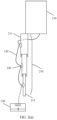
- FIG. 1 is a diagram of continuously supplying power to a mobile apparatus 110 according to an embodiment of this application.
- a power supply apparatus 120 of the vehicle is connected to the mobile apparatus 110 through a harness 130.
- the power supply apparatus 120 may be a battery of the vehicle, or may be a battery apparatus that is separately configured to supply power to the mobile apparatus 110. This is not limited in embodiments of this application.
- the mobile apparatus 110 may be the vehicle door glass of the vehicle.
- the harness 130 may be connected to the mobile apparatus 110 through a connecting member 140.
- a problem of tangling between a harness 130 and another element is avoided in a process in which the harness 130 moves with a mobile apparatus 110, and a plurality of fastening points for fastening the harness 130 are disposed on the multi-stage telescopic member 210, to share a bearing force on the harness 130.
- This improves durability of a connection between the harness 130 and the mobile apparatus 110.
- the apparatus 200 for constraining the harness 130 may further effectively avoid abnormal sounds caused by repeated beating between the harness 130 and another element.
- the mobile apparatus 110 is a power-consuming apparatus, and the power supply apparatus 120 needs to be connected to the mobile apparatus through the harness 130, to continuously supply power to the mobile apparatus 110.
- the harness 130 is also extended or retracted accordingly.
- the one end of the harness 130 may be directly connected to the mobile apparatus 110, for example, connected to the mobile apparatus 110 through a connecting member.
- the one end of the harness 130 may alternatively include a lead head, and is connected to the mobile apparatus 110 through the lead head.
- the harness 130 or the lead head of the harness 130 may be connected to the connecting member 140 of the mobile apparatus 110.
- the harness 130 or the lead head of the harness 130 may be in a sealed connection to the connecting member 140, so that durability of a connection between the harness 130 and the mobile apparatus 110 is further improved.
- the other end of the harness 130 may be directly connected to the power supply apparatus 120.
- the other end of the harness 130 may alternatively include a lead head, and is connected to the power supply apparatus 120 through the lead head.
- the other end of the harness 130 or the lead head of the other end of the harness 130 may be in a sealed connection to the power supply apparatus 120, so that the power supply apparatus 120 supplies power to the mobile apparatus 110 through the harness 130.
- the multi-stage telescopic member 210 includes N stages of components that are slidably sleeved sequentially.
- a width of an i th stage of component is greater than a width of an (i-1) th stage of component, that is, when the multi-stage telescopic member 210 is extended to be longest, the multi-stage telescopic member 210 is narrower at the bottom and wider at the top as a whole.
- the width of the i th stage of component of the multi-stage telescopic member 210 may alternatively be less than the width of the (i-1) th stage of component, that is, when the multi-stage telescopic member 210 is extended to be longest, the multi-stage telescopic member 210 is narrower at the top and wider at the bottom as a whole. This is not limited in embodiments of this application.
- i is a positive integer greater than 1 and less than or equal to N.
- a bottom component 212 of the fastening apparatus 200 may be connected to a support base, and the support base may be a vehicle door sheet metal.
- the multi-stage telescopic member 210 includes the N components that are slidably sleeved sequentially, where N is a positive integer greater than 1.
- N is a positive integer greater than 1.
- the N th stage of component is first pulled up by the lifting glass.
- the N th stage of component pulls up an (N-1) th stage of component, so that the entire multi-stage telescopic member 210 continues to be extended.
- the multi-stage telescopic member 210 may be extended to be longest.
- the N th stage of component is the top component 211.
- the top component 211 may be directly connected to the lifting glass, or may be connected to a slider 111 of the lifting glass shown in FIG. 2(c) .
- the slider is disposed on a glass slide rail and is fastened to the glass, to drive the glass to rise/fall.
- the top component 211 may be specifically connected to the lifting glass through bonding, or may be connected to the lifting glass through another connecting member, provided that the top component 211 is connected to the lifting glass. This is not limited in embodiments of this application.
- a 2 nd stage of component to the N th stage of component fall as a whole with the lifting glass.
- the 2 nd stage of component first falls to be lowest, because the components are slidably sleeved sequentially, a 3 rd stage of component to the N th stage component continue to fall as a whole with the lifting glass.
- a similar process is performed until the lifting glass falls to be lowest.
- the multi-stage telescopic member 210 may be retracted to be shortest, and each stage of component of the multi-stage telescopic member 210 is accommodated by an upper stage or a lower stage of component. Because the bottom component 212 is fixedly connected to the vehicle door sheet metal, the bottom component 212 is not pulled up in the rising/falling process of the lifting glass.
- the bottom component 212 and the vehicle door sheet metal are fixedly connected.
- the bottom component 212 and the vehicle door sheet metal may be not fixedly connected, that is, may be virtually connected. This is also applicable to the foregoing technical solution.
- the bottom component 212 is not necessarily fixedly connected to the vehicle door sheet metal.
- a stage of component other than the top component 211 may be fixedly connected to the vehicle door sheet metal. This is not limited in embodiments of this application.
- FIG. 3 is a diagram of a structure of another fastening apparatus 200 according to an embodiment of this application.
- FIG. 3 is a front view of the fastening apparatus 200.
- FIG. 4 is a diagram of a structure of another fastening apparatus 200 according to an embodiment of this application.
- FIG. 4 is a front view of the fastening apparatus 200.
- connection structure includes a first lapping member 251 and a second lapping member 252, where the first lapping member 251 is disposed at the lower end of the i th stage of component, and the second lapping member 252 is disposed at the upper end of the (i-1) th stage of component.
- connection structure provided in this application may be in another form. This is not limited in this application.
- the apparatus provided in this embodiment of this application includes the fastening point, and the fastening point can bear a part of a weight of the harness 130, to prevent the connecting member between the harness 130 and the door lifting glass from bearing the weight of the entire harness 130.
- This improves durability of a connection between a lead of the harness 130 and the mobile apparatus 110.
- the harness 130 is fastened by using the fastening point, which constrains a movement range of the harness 130 in a process in which the harness 130 moves with the mobile apparatus 110.
- the harness 130 between the fastening points is always in a loose state.
- the fastening points of all stages of components jointly bear the weight of the entire harness 130. This further improves the durability of a connection between the harness 130 and the mobile apparatus 110.
- the harness 130 is fastened by using the plurality of fastening points, which also constrains the movement range of the harness 130 in the process in which the harness 130 moves with the mobile apparatus 110.
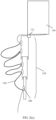
- FIG. 6 is a diagram of a structure of a fastening apparatus 200 according to an embodiment of this application.
- the mobile apparatus 110 is the vehicle door lifting glass. Because housings of most vehicles are set to a streamlined shape, a rising/falling track of the vehicle door lifting glass is a curve. If the multi-stage telescopic member 210 is directly and fixedly connected to the vehicle door sheet metal, it cannot be ensured that the multi-stage telescopic member 210 can rise and fall with the lifting glass. Consequently, the glass is stuck and the multi-stage telescopic member 210 is even damaged in the rising/falling process.
- the rotating shaft 260 may be a rotating rod, or may be a pivot rotating shaft. This is not limited in embodiments of this application.
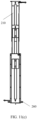
- FIG. 10(a) to FIG. 10(e) are diagrams of a structure of another fastening apparatus 200 according to an embodiment of this application.
- FIG. 10(a) is a diagram of a structure obtained when the multi-stage telescopic member 210 is in an extending process.
- FIG. 10(b) is a diagram of a structure obtained when the multi-stage telescopic member 210 is retracted to be shortest.
- FIG. 10(c) is a sectional view of a first cross section in (a).
- FIG. 10(d) is a sectional view of a second cross section in (a).
- FIG. 10(e) is a diagram of a form of harness 130 disposed in the apparatus shown in FIG. 10(a) to FIG. 10(e) .
- the multi-stage telescopic member 210 shown in FIG. 10(a) to FIG. 10(e) includes two stages of components.
- the harness 130 may be a drag chain harness, and the drag chain harness has good stability.
- a weight of the drag chain also plays a corresponding constraint role on the harness 130, so that the harness 130 is not likely to be tangled by itself.
- a first opening 330 may further be disposed on a surface of each stage of component provided in the foregoing embodiment.
- the surface may be a large surface of the component, and the large surface is a surface with a largest area in surfaces of the component. Due to a constraint function of the drag chain harness, generally, even if the first opening is provided on the surface of the component, the drag chain harness does not overflow from the first opening in a process of extending or retracting the drag chain harness.
- FIG. 10(c) The sectional view of the fastening apparatus 200 presented at the first cross section is shown in FIG. 10(c) .
- a section of a part indicated by 1010 in the figure is a section that is of the drag chain harness and that is along the first cross section, where a left section of the drag chain harness is a section of the one end of the drag chain harness fastened to the top component 211, and a right section of the drag chain harness is a section of the other end of the drag chain harness fastened to the bottom component 212.
- FIG. 10(d) A section of a part indicated by 1010 in the figure is a section that is of the drag chain harness and that is along the second cross section.
- the drag chain harness has a characteristic of constraining the harness, the drag chain harness is not likely to be tangled with another element due to overflowing from the first opening 330 on the surface. Further, the multi-stage telescopic member 210 is lightweight to some extent, so that the fastening apparatus 200 is lighter, and manufacturing costs are reduced.
- the at least one fastening point 220 includes a first fastening point 221 and a second fastening point 222.
- the first fastening point 221 may be disposed on an upper part of the top component 211
- the second fastening point 222 may be disposed on an upper part of the bottom component 212.
- the first fastening point 221 and the second fastening point 222 may be located in space on a same plane perpendicular to an extended/retracted direction of the multi-stage telescopic member 210.
- the drag chain harness is fastened by the two fastening points. Therefore, a length of the drag chain harness can be adjusted, to enable the drag chain harness to distribute in a U shape.
- a drag chain may be added to the harness 130 of a proper length, that is, a length of the harness 130 to which a drag chain needs to be added is determined based on a movement distance of the mobile apparatus 110 connected to the harness 130.
- a drag chain is added to a part of the harness 130, and under a fastening function of the first fastening point 221 and the second fastening point 222, and under a self-weight effect of the drag chain, this part of the harness 130 is freely drooped with the drag chain.
- a left figure shows a state of the drag chain harness in the fastening apparatus 200 when the harness 130 is in a stretched state
- a right figure shows that the drag chain harness is in a U-shaped distribution state as a whole when the multi-stage telescopic member 210 is retracted to be shortest.
- a harness groove 1020 may further be provided below the second fastening point 222 of the bottom component 212, and the harness groove is connected to the second hole 320 of the bottom component 212, so that the redundant harness 130 can be accommodated in the harness groove, and is connected to the power supply apparatus 120 through the second hole 320.
- each stage of component of the multi-stage telescopic member 210 included in the fastening apparatus 200 provided in this embodiment is a baffle plate.
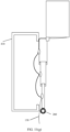
- the apparatus 200 further includes: the accommodation portion 410, where one side of the accommodation portion 410 has a second opening 420, the second opening 420 is disposed opposite to the multi-stage telescopic member 210, and when the multi-stage telescopic member 210 is extended to be longest, a range of the second opening 420 covers all fastening points disposed on the multi-stage telescopic member 210.
- the accommodation portion 410 and the multi-stage telescopic member 210 may be fastened to the same support base 150, or the accommodation portion 410 may be fixedly connected to another base apparatus, provided that the range of the second opening 420 covers all the fastening points disposed on the multi-stage telescopic member 210, to prevent the harness 130 from being stuck in an interlayer between the accommodation portion 410 and the multi-stage telescopic member 210 when the harness 130 is extended or retracted with the multi-stage telescopic member 210.
- a height of the accommodation portion 410 may be greater than a height of the multi-stage telescopic member 210 when the multi-stage telescopic member 210 is extended to be longest, or may be equal to the height of the multi-stage telescopic member 210 when the multi-stage telescopic member 210 is extended to be longest, or may be less than the height of the multi-stage telescopic member 210 when the multi-stage telescopic member 210 is extended to be longest.
- the multi-stage telescopic member 210 can still be extended or retracted when the mobile apparatus 110 moves along the curve, to prevent a case in which the mobile apparatus 110 is stuck and the multi-stage telescopic member 210 is even damaged when the mobile apparatus 110 moves along a non-linear track.
- the fastening apparatus 200 further includes:
- the mobile apparatus 110 can be continuously powered.
- a gap between the accommodation portion 410 and the multi-stage telescopic member 210 may be less than a diameter of the harness 130 and greater than a diameter of a lead led out from two ends of the harness 130, so that the lead led out from the two ends of the harness 130 can pass through the gap.
- the lead led out from the one end of the harness 130 is connected to the mobile apparatus 110, and the lead led out from the other end of the harness 130 is connected to the power supply apparatus 120.
- the mobile apparatus 110 can also be continuous powered. Because the accommodation portion 410 and the multi-stage telescopic member 210 are two apparatuses independent of each other, it is convenient for separate maintenance for the two apparatuses later, and no hole needs to be drilled on the fastening apparatus 200, which simplifies a processing process of the fastening apparatus 200.
- FIG. 11(h) shows the fastening apparatus 200 having the pressure plate 450 according to an embodiment of this application.
- the fastening apparatus 200 further includes: the pressure plate 450, where the pressure plate 450 is disposed on the top component 211, and the pressure plate 450 extends to an inside of the accommodation portion 410, to prevent the harness 130 from overflowing from the second opening 420 of the accommodation portion 410 in a retraction process of the multi-stage telescopic member 210.
- the pressure plate 450 when a fastening point is disposed on the top component 211, the pressure plate 450 may be disposed above the fastening point of the top component 211.
- the pressure plate 450 may alternatively be directly disposed on the upper end surface of the top component 211.
- the pressure plate 450 when no fastening point is disposed on the top component 211, and a fastening point is disposed on a lower stage of component of the top component 211, the pressure plate 450 may be disposed on the top component 211, or the pressure plate 450 may be disposed above the fastening point of the lower stage of component. This is not limited in this application.
- the accommodation portion 410 and the slide rail of the mobile apparatus 110 may be integrally formed. Based on the technical solution, the accommodation portion 410 is used as a part of the slide rail, and space occupied by the apparatus is saved.
- the mobile apparatus 110 included in the vehicle door is liftable vehicle door glass, and the liftable vehicle door glass is connected to the fastening apparatus 200.
- the liftable glass is connected to the fastening apparatus 200 through the elastic connecting member 270.
- the device may be a display, a television, a curtain, building glass, a roof skylight, or the like.
- the disclosed system, apparatus and method may be implemented in other manners.
- the described apparatus embodiment is merely an example.
- division into the units is merely logical function division and may be other division in an actual implementation.
- a plurality of units or components may be combined or integrated into another system, or some features may be ignored or not performed.
- the displayed or discussed mutual couplings or direct couplings or communication connections may be implemented through some interfaces.
- the indirect couplings or communication connections between the apparatuses or units may be implemented in electronic, mechanical, or other forms.
- the units described as separate parts may or may not be physically separate, and parts displayed as units may or may not be physical units, may be located in one position, or may be distributed on a plurality of network units. Some or all of the units may be selected based on actual requirements to achieve the objectives of the solutions of embodiments.
- the functions When the functions are implemented in the form of software functional unit and sold or used as an independent product, the functions may be stored in a computer-readable storage medium. Based on such an understanding, the technical solutions of this application essentially, or the part contributing to the conventional technology, or some of the technical solutions may be implemented in a form of software product.
- the computer software product is stored in a storage medium, and includes several instructions for instructing a computer device (which may be a personal computer, a server, or a network device) to perform all or some of the steps of the methods described in embodiments of this application.
Landscapes
- Engineering & Computer Science (AREA)
- Mechanical Engineering (AREA)
- Chemical & Material Sciences (AREA)
- Combustion & Propulsion (AREA)
- Transportation (AREA)
- Electric Cable Arrangement Between Relatively Moving Parts (AREA)
- Power-Operated Mechanisms For Wings (AREA)
- Window Of Vehicle (AREA)
Abstract


Description
- This application relates to the mechanical field, and specifically, to a fastening apparatus, a vehicle door, a vehicle, and a device.
- With development of science and technology, conventional objects such as a glass door and a glass window are also given more functions, for example, a light emitting and color changing function and a touch function. To implement the functions, glass needs to be continuously powered through a harness. However, in an application scenario like an intelligent vehicle, glass usually needs to perform a rising/falling action. In an entire rising/falling process, one end of a harness is connected to a glass component through a connecting member, and the harness is extended or retracted as the glass moves. In addition, in a process of extending or retracting the harness, the harness is tangled with another element that drives the glass to rise/fall, and in a process of rising/falling with the glass, the harness shakes and repeatedly beats with another element, resulting in abnormal sounds. In addition, the foregoing problems also exist in an application scenario of supplying power to a liftable screen of a device like a smart home device or a smartphone through the harness.
- Therefore, in a process of supplying power to a mobile apparatus like the lifting glass or the lifting screen, how to improve durability of fastening the harness and the mobile apparatus, how to avoid tangling between the harness and the another element, and how to avoid the abnormal sounds caused by repeated beating between the harness and the another element are problems to be urgently resolved.
- This application provides a fastening apparatus, a vehicle door, a vehicle, and a device, to fasten a harness to a multi-stage telescopic member through at least one fastening point, so that the at least one fastening point shares a bearing force on the harness. The multi-stage telescopic member is connected to a mobile apparatus, so that durability of fastening the harness and the mobile apparatus can be improved, tangling between the harness and another element can be avoided, and abnormal sounds caused by repeated beating between the harness and another element can be effectively avoided.
- According to a first aspect, a fastening apparatus is provided, where the fastening apparatus includes: a multi-stage telescopic member, where the multi-stage telescopic member includes a plurality of components that are slidably sleeved sequentially, a component located at the top is a top component, and the top component is configured to connect to a mobile apparatus, so that the multi-stage telescopic member is extended or retracted as the mobile apparatus moves; and at least one fastening point, where the at least one fastening point is disposed on the multi-stage telescopic member, the at least one fastening point is configured to fasten a harness, one end of the harness is configured to connect to the mobile apparatus, and the other end of the harness is configured to connect to a power supply apparatus, so that the power supply apparatus supplies power to the mobile apparatus through the harness.
- For example, the mobile apparatus is a power-consuming apparatus, and the power supply apparatus needs to be connected to the mobile apparatus through the harness, to continuously supply power to the mobile apparatus. In a process of movement of the mobile apparatus, the harness is also extended or retracted accordingly.
- For example, the one end of the harness may be directly connected to the mobile apparatus, for example, connected to the mobile apparatus through a connecting member. The one end of the harness may alternatively include a lead head, and is connected to the mobile apparatus through the lead head. The harness or the lead head of the harness may be connected to the connecting member of the mobile apparatus. Further, the harness or the lead head of the harness may be in a sealed connection to the connecting member, so that durability of fastening the harness and the mobile apparatus is further improved. Similarly, the other end of the harness may be directly connected to the power supply apparatus. The other end of the harness may alternatively include a lead head, and is connected to the power supply apparatus through the lead head. Further, the other end of the harness or the lead head of the other end of the harness may be in a sealed connection to the power supply apparatus, so that the power supply apparatus supplies power to the mobile apparatus through the harness.
- For example, when the multi-stage telescopic member is extended to be longest, the multi-stage telescopic member may be narrower at the bottom and wider at the top as a whole; or when the multi-stage telescopic member is extended to be longest, the multi-stage telescopic member may be narrower at the top and wider at the bottom as a whole.
- For example, a component located at the bottom is a bottom component, and the bottom component and a support base may be fixedly connected, or may be not fixedly connected, that is, may be virtually connected.
- For example, the harness may be fastened to the fastening point by using a fastener, or may be fastened by using a binding strap, or may be fastened in a welding or directly adhesive bonding manner.
- Based on the foregoing technical solution, the fastening point bears a part of a weight of the harness, to prevent the connecting member between the harness and the mobile apparatus from bearing the weight of the entire harness, so as to improve durability of a connection between the harness and the mobile apparatus. In addition, the harness is fastened by using the fastening point, which constrains a movement range of the harness in a process in which the harness moves with the mobile apparatus.
- With reference to the first aspect, in some implementations of the first aspect, a component located at the bottom is a bottom component, the bottom component is connected to a support base, and the fastening apparatus further includes: a rotating shaft, where the rotating shaft is disposed between the bottom component and the support base, so that the multi-stage telescopic member rotates along an axis of the rotating shaft.
- For example, the rotating shaft may be a rotating rod, or may be a pivot rotating shaft.
- Based on the foregoing technical solution, the rotating shaft is disposed between the multi-stage telescopic member and the support base, so that the multi-stage telescopic member can automatically adjust an angle of the multi-stage telescopic member in a process in which the mobile apparatus moves along a curve, to ensure that the mobile apparatus can normally move along a non-linear track, and avoid a case in which the mobile apparatus is stuck and the multi-stage telescopic member is even damaged when the mobile apparatus moves along the curve.
- With reference to the first aspect, in some implementations of the first aspect, the fastening apparatus further includes an elastic connecting member, where the elastic connecting member is disposed between the top component and the mobile apparatus, so that the multi-stage telescopic member is capable of being pulled to be extended or retracted when the mobile apparatus moves.
- For example, when the mobile apparatus moves along the curve, even if there is no rotating shaft to adjust the angle of the multi-stage telescopic member, because the connecting member between the top component and the mobile apparatus is elastic, a force that is of the mobile apparatus and that is in a direction of a tangent of a curve movement track can be decomposed into a force and a force in a direction parallel to a direction of the multi-stage telescopic member, so that the multi-stage telescopic member can still be pulled to be extended or retracted.
- Based on the foregoing technical solution, the top component of the multi-stage telescopic apparatus is connected to the mobile apparatus through the elastic connecting member, so that in a process in which the mobile apparatus moves along the curve, through the elastic connecting member, the force in the direction parallel to the direction of the multi-stage telescopic member can be obtained through decomposing, and the multi-stage telescopic member can still be pulled to be extended or retracted, to ensure that the mobile apparatus can normally move along the curve, and avoid a case in which the mobile apparatus is stuck and the multi-stage telescopic member is even damaged when the mobile apparatus moves along the non-linear track.
- With reference to the first aspect, in some implementations of the first aspect, a quantity of the at least one fastening point is the same as a quantity of the components included in the multi-stage telescopic member, and one fastening point is disposed on each stage of component.
- Based on the foregoing technical solution, the fastening points of all stages of components jointly bear the weight of the entire harness. This further improves the durability of a connection between the harness and the mobile apparatus. In addition, the harness is fastened by using the plurality of fastening points, which also constrains the movement range of the harness in the process in which the harness moves with the mobile apparatus.
- With reference to the first aspect, in some implementations of the first aspect, the component is of a hollow structure, and is configured to accommodate the harness.
- Based on the foregoing technical solution, the multi-stage telescopic member is of a hollow structure and is configured to accommodate the harness, which further constrains the movement range of the harness. This effectively avoids tangling between the harness and another element, and also avoids an abnormal sound caused by beating between the harness and another element.
- With reference to the first aspect, in some implementations of the first aspect, the fastening apparatus further includes: a first hole, where the first hole is provided on the top component, and is configured to lead out the one end of the harness; and a second hole, where the second hole is provided on the bottom component, and is configured to lead out the other end of the harness.
- Based on the foregoing technical solution, closed space is provided for the harness, and is used to accommodate the harness, and the first hole and the second hole are provided on the multi-stage telescopic member, so that the harness is connected to the mobile apparatus and the power supply apparatus separately, to continuously supply power to the mobile apparatus.
- With reference to the first aspect, in some implementations of the first aspect, the at least one fastening point includes a first fastening point and a second fastening point, the first fastening point is disposed on the top component, the second fastening point is disposed on the bottom component, and when the multi-stage telescopic member is retracted to be shortest, the harness between the first fastening point and the second fastening point is distributed in a U shape.
- Based on this technical solution, there is no harness stacked together in the bottom component, so that a case in which the harness is tangled by itself can be effectively prevented.
- With reference to the first aspect, in some implementations of the first aspect, the harness is a drag chain harness.
- Based on the foregoing technical solution, the drag chain harness has characteristics of good stability and high durability. A weight of the drag chain may also play a corresponding constraint role on the harness, so that the harness is not likely to be tangled by itself.
- With reference to the first aspect, in some implementations of the first aspect, a first opening is provided on a surface of the component.
- For example, the surface of the component may be a large surface of the component, and the large surface is a surface with a largest area in surfaces of the component, or may be another surface. Due to a constraint function of the drag chain harness, generally, even if the first opening is provided on the surface of the component, the drag chain harness does not overflow from the first opening in a process of extending or retracting the drag chain harness.
- Based on the foregoing technical solution, because the drag chain harness has a characteristic of constraining the harness, the drag chain harness is not likely to be tangled with another element due to overflowing from the first opening on the surface of the component. Further, the multi-stage telescopic member is lightweight to some extent, so that the fastening apparatus is lighter, and manufacturing costs are reduced.
- With reference to the first aspect, in some implementations of the first aspect, the component is a baffle plate, and the fastening apparatus further includes: an accommodation portion, where one side of the accommodation portion has a second opening, the second opening is disposed opposite to the multi-stage telescopic member, and when the multi-stage telescopic member is extended to be longest, a range of the second opening covers all the at least one fastening point disposed on the multi-stage telescopic member.
- For example, the accommodation portion may be of a box-type structure, for example, may be a harness box having the second opening on the one side.
- For example, the one side having the second opening may be a large surface of the accommodation portion, or may be a side surface of the accommodation portion. The side surface is a surface that is connected to the large surface and that is other than an upper end surface or a lower end surface of the accommodation portion.
- Based on the foregoing technical solution, the accommodation portion is configured to accommodate the harness fastened to the multi-stage telescopic member, to further limit the movement range of the harness when the harness moves with the mobile apparatus. This can effectively avoid tangling between the harness and another element, and also avoid an abnormal sound caused by beating between the harness and another element.
- With reference to the first aspect, in some implementations of the first aspect, a lower end of the second opening is connected to the bottom component, and the fastening apparatus further includes: a third hole, where the third hole is provided at an upper end of the accommodation portion or the top component, and is configured to lead out the one end of the harness; and a fourth hole, where the fourth hole is provided at a lower end of the accommodation portion or the bottom component, and is configured to lead out the other end of the harness.
- Based on the foregoing technical solution, closed space is provided for the harness, and is used to accommodate the harness, and the third hole and the fourth hole are provided on the multi-stage telescopic member or the accommodation portion, so that the harness is connected to the mobile apparatus and the power supply apparatus separately, to continuously supply power to the mobile apparatus.
- With reference to the first aspect, in some implementations of the first aspect, the fastening apparatus further includes a pressure plate, where the pressure plate is disposed on the top component and extends to an inside of the accommodation portion, to prevent the harness from overflowing from the second opening in a process of retracting the multi-stage telescopic member.
- For example, when a fastening point is disposed on the top component, the pressure plate may be disposed above the fastening point of the top component. The pressure plate may alternatively be directly disposed on the upper end surface of the top component. For example, when no fastening point is disposed on the top component, and a fastening point is disposed on a lower stage of component of the top component, the pressure plate may be disposed on the top component, or the pressure plate may be disposed above a fastening point of the lower stage of component.
- Based on the foregoing technical solution, a phenomenon in which the harness disorders in the accommodation portion and overflows from the accommodation portion in the retraction process, resulting in tangling between the harness and another element can be effectively prevented.
- With reference to the first aspect, in some implementations of the first aspect, the accommodation portion and a slide rail of the mobile apparatus are integrally formed.
- Based on the foregoing technical solution, the accommodation portion is used as a part of the slide rail, and space occupied by the apparatus is saved.
- With reference to the first aspect, in some implementations of the first aspect, the harness is a flat harness.
- Based on the foregoing technical solution, because the flat harness is likely to bend, and is likely to be in a form of stacking with each other after being bent. Therefore, the flat harness is used, to effectively avoid a problem that the harness is tangled by itself in the process of moving with the mobile apparatus, and can also avoid a problem that the harness is tangled with another element.
- According to a second aspect, a vehicle door is provided, where the vehicle door includes the fastening apparatus and the mobile apparatus according to any one of the possible implementations of the first aspect.
- With reference to the second aspect, in some implementations of the second aspect, the mobile apparatus included in the vehicle door is liftable vehicle door glass, and the liftable vehicle door glass is connected to the fastening apparatus.
- With reference to the second aspect, in some implementations of the second aspect, the liftable vehicle door glass is connected to the fastening apparatus through an elastic connecting member.
- According to a third aspect, a vehicle is provided, where the vehicle includes the fastening apparatus according to any one of the possible implementations of the first aspect, or the vehicle door according to any one of the possible implementations of the second aspect.
- According to a fourth aspect, a device is provided, where the device includes the fastening apparatus according to any one of the possible implementations of the first aspect.
- For example, the device may be a display, a television, a curtain, building glass, a roof skylight, or the like.
-
-
FIG. 1 is a diagram of continuously supplying power to amobile apparatus 110 according to an embodiment of this application; -
FIG. 2(a) to FIG. 2(c) are diagrams of a structure of a fastening apparatus 200 according to an embodiment of this application; -
FIG. 3 is a diagram of a structure of another fastening apparatus 200 according to an embodiment of this application; -
FIG. 4 is a diagram of a structure of another fastening apparatus 200 according to an embodiment of this application; -
FIG. 5 is a diagram of a structure of another fastening apparatus 200 according to an embodiment of this application; -
FIG. 6 is a diagram of a structure of another fastening apparatus 200 according to an embodiment of this application; -
FIG. 7 is a diagram of a structure of another fastening apparatus 200 according to an embodiment of this application; -
FIG. 8 is a diagram of a structure of another fastening apparatus 200 according to an embodiment of this application; -
FIG. 9 is a diagram of a structure of another fastening apparatus 200 according to an embodiment of this application; -
FIG. 10(a) to FIG. 10(e) are diagrams of a structure of another fastening apparatus 200 according to an embodiment of this application; and -
FIG. 11(a) to FIG. 11(h) are diagrams of a structure of another fastening apparatus 200 according to an embodiment of this application. - The following describes technical solutions of this application with reference to the accompanying drawings.
- A fastening apparatus 200 provided in this application is applicable to a vehicle, and is used together with lifting glass of the vehicle. The vehicle (sometimes referred to as a car for short) in this application is a vehicle in a generalized concept, and may be a transportation means (for example, an automobile, a truck, a motorcycle, a train, an airplane, or a ship), an industrial vehicle (for example, a fork lift truck, a trailer, or a tractor), an engineering vehicle (for example, an excavator, a bulldozer, or a crane), an agricultural device (for example, a lawn mower, or a harvester), a recreation device, or a toy vehicle. A type of the vehicle is not limited in this application. In addition, the fastening apparatus 200 provided in this application is further applicable to a scenario in which the fastening apparatus 200 is extended or retracted as another power supply object moves.
- For example, in a scenario in which vehicle door glass of the vehicle is powered, to implement functions such as electrochromism and touch of the vehicle door glass, the vehicle door glass needs to be continuously powered.
FIG. 1 is a diagram of continuously supplying power to amobile apparatus 110 according to an embodiment of this application. Generally, apower supply apparatus 120 of the vehicle is connected to themobile apparatus 110 through aharness 130. Thepower supply apparatus 120 may be a battery of the vehicle, or may be a battery apparatus that is separately configured to supply power to themobile apparatus 110. This is not limited in embodiments of this application. Themobile apparatus 110 may be the vehicle door glass of the vehicle. Further, theharness 130 may be connected to themobile apparatus 110 through a connectingmember 140. When themobile apparatus 110 rises, theharness 130 is extended as themobile apparatus 110 rises, and when themobile apparatus 110 falls, theharness 130 is retracted as themobile apparatus 110 falls. However, in a rising/falling process of themobile apparatus 110, there are the following problems. - (1) Tangling problem: After the
mobile apparatus 110 falls, in a process of retracting theharness 130, a bent part of theharness 130 and an accessory of a vehicle door sheet metal, for example, a glass lifting slide rail and a door reinforcing beam, are tangled, causing theharness 130 to be bound. Then, if themobile apparatus 110 rises, theharness 130 may be broken. - (2) Durability problem: In the rising/falling process of the
mobile apparatus 110, the connectingmember 140 between theharness 130 and themobile apparatus 110 needs to bear a weight of theharness 130, and especially when themobile apparatus 110 rises to a limit, this fastening point may need to bear the weight of theentire harness 130. Therefore, in a process of repeated rising and falling of the vehicle door glass, durability of a connection between theharness 130 and the connectingmember 140 cannot be ensured. - (3) Problem of controlling an abnormal sound caused when the
harness 130 is suspended and shakes: In the rising/falling process of themobile apparatus 110, theharness 130 shakes and repeatedly beats with a peripheral component of theharness 130, resulting in abnormal sounds. - The foregoing uses the scenario in which the vehicle door glass of the vehicle is powered as an example, to describe current problems in the scenario. Similarly, in another application scenario in which the
mobile apparatus 110 needs to be continuously powered through theharness 130, for example, a scenario of rising/falling of a mechanical arm, the problems also exist. However, all existing technical solutions have defects such as complex processes, difficult mass production, and poor durability. In view of this, this application provides a fastening apparatus 200. By using a multi-stagetelescopic member 210, a problem of tangling between aharness 130 and another element is avoided in a process in which theharness 130 moves with amobile apparatus 110, and a plurality of fastening points for fastening theharness 130 are disposed on the multi-stagetelescopic member 210, to share a bearing force on theharness 130. This improves durability of a connection between theharness 130 and themobile apparatus 110. In addition, the apparatus 200 for constraining theharness 130 may further effectively avoid abnormal sounds caused by repeated beating between theharness 130 and another element. - In an embodiment of this application, an application scenario in which the
mobile apparatus 110 is continuously powered through theharness 130 is used to describe the apparatus 200 for constraining theharness 130 provided in embodiments of this application. -
FIG. 2(a) to FIG. 2(c) are diagrams of a structure of a fastening apparatus 200 according to an embodiment of this application.FIG. 2(a) to FIG. 2(c) are side cross-sectional views of the fastening apparatus 200.FIG. 2(a) is a diagram of a structure obtained when the fastening apparatus 200 is extended to be longest as amobile apparatus 110 moves.FIG. 2(b) is a diagram of a structure obtained when the fastening apparatus 200 is retracted to be shortest as themobile apparatus 110 moves.FIG. 2(c) is a diagram of disposing a fastening point when aharness 130 is excessively long. - The apparatus 200 includes:
- a multi-stage
telescopic member 210, where the multi-stagetelescopic member 210 includes a plurality of components that are slidably sleeved sequentially, a component located at the top is atop component 211, and thetop component 211 is configured to connect to themobile apparatus 110, so that the multi-stagetelescopic member 210 is extended or retracted as themobile apparatus 110 moves; and - at least one
fastening point 220, where the at least onefastening point 220 is disposed on the multi-stagetelescopic member 210, the at least onefastening point 220 is configured to fasten theharness 130, one end of theharness 130 is configured to connect to themobile apparatus 110, and the other end of theharness 130 is configured to connect to apower supply apparatus 120, so that thepower supply apparatus 120 supplies power to themobile apparatus 110 through theharness 130. - The
top component 211 is a component that is located at the top of the entire multi-stagetelescopic member 210 when the multi-stagetelescopic member 210 is extended to be longest along a direction perpendicular to the ground. - In an embodiment, the
mobile apparatus 110 is a power-consuming apparatus, and thepower supply apparatus 120 needs to be connected to the mobile apparatus through theharness 130, to continuously supply power to themobile apparatus 110. In a process of movement of themobile apparatus 110, theharness 130 is also extended or retracted accordingly. - In some possible embodiments, the one end of the
harness 130 may be directly connected to themobile apparatus 110, for example, connected to themobile apparatus 110 through a connecting member. The one end of theharness 130 may alternatively include a lead head, and is connected to themobile apparatus 110 through the lead head. Theharness 130 or the lead head of theharness 130 may be connected to the connectingmember 140 of themobile apparatus 110. Further, theharness 130 or the lead head of theharness 130 may be in a sealed connection to the connectingmember 140, so that durability of a connection between theharness 130 and themobile apparatus 110 is further improved. Similarly, the other end of theharness 130 may be directly connected to thepower supply apparatus 120. The other end of theharness 130 may alternatively include a lead head, and is connected to thepower supply apparatus 120 through the lead head. Further, the other end of theharness 130 or the lead head of the other end of theharness 130 may be in a sealed connection to thepower supply apparatus 120, so that thepower supply apparatus 120 supplies power to themobile apparatus 110 through theharness 130. - In some possible embodiments, the multi-stage
telescopic member 210 includes N stages of components that are slidably sleeved sequentially. A width of an ith stage of component is greater than a width of an (i-1)th stage of component, that is, when the multi-stagetelescopic member 210 is extended to be longest, the multi-stagetelescopic member 210 is narrower at the bottom and wider at the top as a whole. The width of the ith stage of component of the multi-stagetelescopic member 210 may alternatively be less than the width of the (i-1)th stage of component, that is, when the multi-stagetelescopic member 210 is extended to be longest, the multi-stagetelescopic member 210 is narrower at the top and wider at the bottom as a whole. This is not limited in embodiments of this application. Herein, i is a positive integer greater than 1 and less than or equal to N. - For ease of description, the following uses an example in which the
mobile apparatus 110 is lifting glass of a vehicle door for description. Abottom component 212 of the fastening apparatus 200 may be connected to a support base, and the support base may be a vehicle door sheet metal. - As shown in
FIG. 2(a) , in an embodiment, the multi-stagetelescopic member 210 includes the N components that are slidably sleeved sequentially, where N is a positive integer greater than 1. In a process in which the lifting glass rises, because a top end of an Nth stage of component of the multi-stagetelescopic member 210 is connected to the lifting glass, the Nth stage of component is first pulled up by the lifting glass. When the Nth stage of component is pulled up to be highest, because the components are slidably sleeved sequentially, the Nth stage of component pulls up an (N-1)th stage of component, so that the entire multi-stagetelescopic member 210 continues to be extended. A similar process is performed until the lifting glass rises to be highest. In this case, the multi-stagetelescopic member 210 may be extended to be longest. The Nth stage of component is thetop component 211. Thetop component 211 may be directly connected to the lifting glass, or may be connected to aslider 111 of the lifting glass shown inFIG. 2(c) . The slider is disposed on a glass slide rail and is fastened to the glass, to drive the glass to rise/fall. Certainly, thetop component 211 may be specifically connected to the lifting glass through bonding, or may be connected to the lifting glass through another connecting member, provided that thetop component 211 is connected to the lifting glass. This is not limited in embodiments of this application. - On the contrary, as shown in
FIG. 2(b) , in a process in which the lifting glass falls, a 2nd stage of component to the Nth stage of component fall as a whole with the lifting glass. When the 2nd stage of component first falls to be lowest, because the components are slidably sleeved sequentially, a 3rd stage of component to the Nth stage component continue to fall as a whole with the lifting glass. A similar process is performed until the lifting glass falls to be lowest. In this case, the multi-stagetelescopic member 210 may be retracted to be shortest, and each stage of component of the multi-stagetelescopic member 210 is accommodated by an upper stage or a lower stage of component. Because thebottom component 212 is fixedly connected to the vehicle door sheet metal, thebottom component 212 is not pulled up in the rising/falling process of the lifting glass. - In the foregoing embodiment, the
bottom component 212 and the vehicle door sheet metal are fixedly connected. In some other possible embodiments, thebottom component 212 and the vehicle door sheet metal may be not fixedly connected, that is, may be virtually connected. This is also applicable to the foregoing technical solution. Similarly, thebottom component 212 is not necessarily fixedly connected to the vehicle door sheet metal. Alternatively, a stage of component other than thetop component 211 may be fixedly connected to the vehicle door sheet metal. This is not limited in embodiments of this application. - In some possible embodiments, in a process in which the lifting glass continuously rises, when the ith stage of component is pulled up to be highest, the (i-1)th stage of component needs to be pulled up through the connecting member. The connecting member may be shown in
FIG. 3. FIG. 3 is a diagram of a structure of another fastening apparatus 200 according to an embodiment of this application.FIG. 3 is a front view of the fastening apparatus 200. - In an example shown in
FIG. 3 , i is equal to N, and the connecting member includes aslide rail 230 and afastening button 240, where thefastening button 240 may be disposed at a lower end of the ith stage of component, and theslide rail 230 may be disposed on the (i-1)th stage of component. Theslide rail 230 is a linear slide rail and is parallel to an extended/retracted direction of the multi-stagetelescopic member 210. Theslide rail 230 may extend from an upper end to a lower end of the (i-1)th stage of component, or from an upper end to a middle portion of the (i-1)th stage of component. A projection that is of thefastening button 240 and that is on the (i-1)th stage of component is in a straight line with the slide rail. - In addition, the connecting member may be shown in
FIG. 4. FIG. 4 is a diagram of a structure of another fastening apparatus 200 according to an embodiment of this application.FIG. 4 is a front view of the fastening apparatus 200. - In an example shown in
FIG. 4 , i is equal to N, and this connection structure includes afirst lapping member 251 and asecond lapping member 252, where thefirst lapping member 251 is disposed at the lower end of the ith stage of component, and thesecond lapping member 252 is disposed at the upper end of the (i-1)th stage of component. In addition, the connection structure provided in this application may be in another form. This is not limited in this application. - In some possible embodiments, the connecting member between the ith stage of component and the (i-1)th stage of component may be disposed below a fastening point of the (i-1)th stage of component. In this way, when the multi-stage
telescopic member 210 is retracted to be shortest, theharness 130 is not clamped in an interlayer between the components. Alternatively,FIG. 5 is a diagram of a structure of another fastening apparatus 200 according to an embodiment of this application.FIG. 5 is a front view of the fastening apparatus 200. The fastening point is disposed in an edge area of a side of each stage of component, and the edge area is not an overlapping area that is of components and that occurs in a state in which each stage of component is accommodated by an upper stage of component or a lower stage of component. This structure can also prevent theharness 130 from being clamped in an interlayer between the components. - In some possible embodiments, the
harness 130 may be fastened to the fastening point by using a fastener, or theharness 130 may be fastened by using a binding strap, or theharness 130 may be fastened in a welding or direct adhesive bonding manner. A specific manner of fastening theharness 130 to the fastening point is not limited in embodiments of this application. - Based on the foregoing technical solution, the apparatus provided in this embodiment of this application includes the fastening point, and the fastening point can bear a part of a weight of the
harness 130, to prevent the connecting member between theharness 130 and the door lifting glass from bearing the weight of theentire harness 130. This improves durability of a connection between a lead of theharness 130 and themobile apparatus 110. In addition, theharness 130 is fastened by using the fastening point, which constrains a movement range of theharness 130 in a process in which theharness 130 moves with themobile apparatus 110. - In some possible embodiments, each stage of component in the multi-stage
telescopic member 210 is provided with one fastening point described above. In addition, as shown inFIG. 2(c) , when theharness 130 is excessively long, a plurality of fastening points described above may further be disposed on a stage of component, and theharness 130 is bent to a proper length by using the fastening points. - In some possible embodiments, in a process in which the multi-stage
telescopic member 210 is extended to be longest, theharness 130 between the fastening points is always in a loose state. - Based on the foregoing technical solution, the fastening points of all stages of components jointly bear the weight of the
entire harness 130. This further improves the durability of a connection between theharness 130 and themobile apparatus 110. In addition, theharness 130 is fastened by using the plurality of fastening points, which also constrains the movement range of theharness 130 in the process in which theharness 130 moves with themobile apparatus 110. -
FIG. 6 is a diagram of a structure of a fastening apparatus 200 according to an embodiment of this application. - The apparatus further includes:
arotating shaft 260, where therotating shaft 260 is disposed between an outer surface of thebottom component 212 and asupport base 150, to connect thebottom component 212 and thesupport base 150, and enable the multi-stagetelescopic member 210 to rotate along an axis of therotating shaft 260. - Similar to the
top component 211 located at the top, a component located at the bottom is a component located at the bottom of the entire multi-stagetelescopic member 210 when the multi-stagetelescopic member 210 is extended to be longest along the direction perpendicular to the ground. - For example, the
mobile apparatus 110 is the vehicle door lifting glass. Because housings of most vehicles are set to a streamlined shape, a rising/falling track of the vehicle door lifting glass is a curve. If the multi-stagetelescopic member 210 is directly and fixedly connected to the vehicle door sheet metal, it cannot be ensured that the multi-stagetelescopic member 210 can rise and fall with the lifting glass. Consequently, the glass is stuck and the multi-stagetelescopic member 210 is even damaged in the rising/falling process. - Therefore, the outer surface of the
bottom component 212 is connected to the vehicle door sheet metal through therotating shaft 260. Therotating shaft 260 may be a rotating rod, or may be a pivot rotating shaft. This is not limited in embodiments of this application. - When the lifting glass rises along the curve, while driving the Nth stage of component to rise, the lifting glass also drives the
rotating shaft 260 to rotate along the shaft axis, to adjust an angle of the multi-stagetelescopic member 210, so as to ensure effective rising/falling movement along the curve in the rising/falling process of the glass. - In some possible embodiments, when the
mobile apparatus 110 is a power-consuming apparatus other than the lifting glass, themobile apparatus 110 may move along an irregular track. The technical solution provided in the foregoing embodiment is also applicable to this case. - Based on the foregoing technical solution, the
rotating shaft 260 is disposed between the multi-stagetelescopic member 210 and thesupport base 150, to ensure that the multi-stagetelescopic member 210 can automatically adjust the angle of the multi-stagetelescopic member 210 in a process in which themobile apparatus 110 moves along a non-linear track, so as to ensure that themobile apparatus 110 can normally move along the non-linear track, and avoid a case in which themobile apparatus 110 is stuck and the multi-stagetelescopic member 210 is even damaged when themobile apparatus 110 moves along the curve. -
FIG. 7 is a diagram of a structure of another fastening apparatus 200 according to an embodiment of this application. - The fastening apparatus 200 may further include:
an elastic connectingmember 270, where the elastic connectingmember 270 is disposed between thetop component 211 and themobile apparatus 110, so that the multi-stagetelescopic member 210 is still capable of being pulled to be extended or retracted when themobile apparatus 110 moves along the curve. This embodiment is applicable to a case in which norotating shaft 260 is disposed between thebottom component 212 of the multi-stagetelescopic member 210 and thesupport base 150. - When the
mobile apparatus 110 moves along the curve, even if there is norotating shaft 260 to adjust the angle of the multi-stagetelescopic member 210, because the connecting member between thetop component 211 and themobile apparatus 110 is elastic, a force F that is of themobile apparatus 110 and that is in a direction of a tangent of a curve movement track can be decomposed into a force and a force F1 in a direction parallel to a direction of the multi-stagetelescopic member 210, so that the multi-stagetelescopic member 210 can still be pulled by themobile apparatus 110 to be extended or retracted. - In some possible embodiments, when the
mobile apparatus 110 is a power-consuming apparatus other than the lifting glass, themobile apparatus 110 may move along an irregular track. The technical solution provided in the foregoing embodiment is also applicable to this case. Certainly, the technical solution provided in this embodiment is also applicable to a case in which therotating shaft 260 is disposed between thebottom component 212 and thesupport base 150. - Based on the foregoing technical solution, the
top component 211 of the multi-stage telescopic apparatus is connected to themobile apparatus 110 through the elastic connectingmember 270, to ensure that in a process in which themobile apparatus 110 moves along the non-linear track, through the elastic connectingmember 270, the force F1 in the direction parallel to the direction of the multi-stagetelescopic member 210 can be obtained through decomposing, so that the multi-stagetelescopic member 210 can still be pulled to be extended or retracted, so as to ensure that themobile apparatus 110 can normally move along the non-linear track, and avoid a case in which themobile apparatus 110 is stuck and the multi-stagetelescopic member 210 is even damaged when themobile apparatus 110 moves along the non-linear track. -
FIG. 8 is a diagram of a structure of another fastening apparatus 200 according to an embodiment of this application. In this embodiment, each stage of component of the multi-stagetelescopic member 210 included in the fastening apparatus 200 is of a hollow structure. For example, the hollow structure may be a structure in a form of harness box, and is configured to accommodate theharness 130. - In some possible embodiments, when the multi-stage
telescopic member 210 includes two components that are slidably sleeved sequentially, because thetop component 211 and thebottom component 212 are slidably sleeved, a lower end surface of thetop component 211 and an upper end surface of thebottom component 212 are both non-closed, so that theharness 130 can be disposed through all the stages of components of the multi-stagetelescopic member 210.FIG. 9 is a diagram of a structure of another fastening apparatus 200 according to an embodiment of this application. An upper end surface of thetop component 211 may alternatively be non-closed, so that one end of theharness 130 is led out, and the one end of theharness 130 is connected to themobile apparatus 110. Certainly, the upper end surface of thetop component 211 may alternatively be closed, and afirst hole 310 needs to be provided, so that the one end of theharness 130 is led out, and the one end of theharness 130 is connected to themobile apparatus 110, to better accommodate theharness 130. Because thebottom component 212 is in contact with thesupport base 150, regardless of whether a lower end surface of thebottom component 212 is closed, theharness 130 does not fall off from the multi-stagetelescopic member 210 in a retraction process. Therefore, asecond hole 320 needs to be provided on thebottom component 212, to lead out the other end of theharness 130, so that the other end of theharness 130 is connected to thepower supply apparatus 120, to continuously supply power to themobile apparatus 110. - When the multi-stage
telescopic member 210 includes more than two components that are slidably sleeved sequentially, for ease of description, in this embodiment of this application, components other than thetop component 211 and thebottom component 212 of the multi-stagetelescopic member 210 are collectively referred to as middle components. Because the multi-stagetelescopic member 210 includes the plurality of components that are slidably sleeved sequentially, upper end surfaces and lower end surfaces of the middle components are non-closed, so that theharness 130 can be disposed through all the stages of components of the entire multi-stagetelescopic member 210. The upper end surface of thetop component 211 may alternatively be non-closed, so that the one end of theharness 130 is led out, and the one end of theharness 130 is connected to themobile apparatus 110. Certainly, and the upper end surface of thetop component 211 may alternatively be closed, and thefirst hole 310 needs to be provided, to lead out the one end of theharness 130, so that the end of theharness 130 is connected to themobile apparatus 110. Because thebottom component 212 is in contact with thesupport base 150, regardless of whether the lower end surface of thebottom component 212 is closed, theharness 130 does not fall off from the multi-stagetelescopic member 210 in the retraction process. Therefore, thesecond hole 320 needs to be provided on thebottom component 212, to lead out the other end of theharness 130, so that the other end of theharness 130 is connected to thepower supply apparatus 120, to continuously supply power to themobile apparatus 110. - Based on the foregoing technical solution, the multi-stage
telescopic member 210 is of a hollow structure and is configured to accommodate theharness 130, which further constrains the movement range of theharness 130. This effectively avoids tangling between theharness 130 and another element, and also avoids an abnormal sound caused by beating between theharness 130 and another element. -
FIG. 10(a) to FIG. 10(e) are diagrams of a structure of another fastening apparatus 200 according to an embodiment of this application.FIG. 10(a) is a diagram of a structure obtained when the multi-stagetelescopic member 210 is in an extending process.FIG. 10(b) is a diagram of a structure obtained when the multi-stagetelescopic member 210 is retracted to be shortest.FIG. 10(c) is a sectional view of a first cross section in (a).FIG. 10(d) is a sectional view of a second cross section in (a).FIG. 10(e) is a diagram of a form ofharness 130 disposed in the apparatus shown inFIG. 10(a) to FIG. 10(e) . The multi-stagetelescopic member 210 shown inFIG. 10(a) to FIG. 10(e) includes two stages of components. - Based on the fastening apparatus 200 provided in the foregoing embodiment, the
harness 130 may be a drag chain harness, and the drag chain harness has good stability. A weight of the drag chain also plays a corresponding constraint role on theharness 130, so that theharness 130 is not likely to be tangled by itself. - Therefore, a first opening 330 may further be disposed on a surface of each stage of component provided in the foregoing embodiment. The surface may be a large surface of the component, and the large surface is a surface with a largest area in surfaces of the component. Due to a constraint function of the drag chain harness, generally, even if the first opening is provided on the surface of the component, the drag chain harness does not overflow from the first opening in a process of extending or retracting the drag chain harness.
- The sectional view of the fastening apparatus 200 presented at the first cross section is shown in
FIG. 10(c) . A section of a part indicated by 1010 in the figure is a section that is of the drag chain harness and that is along the first cross section, where a left section of the drag chain harness is a section of the one end of the drag chain harness fastened to thetop component 211, and a right section of the drag chain harness is a section of the other end of the drag chain harness fastened to thebottom component 212. In addition, the sectional view of the fastening apparatus 200 presented at the second cross section is shown inFIG. 10(d) . A section of a part indicated by 1010 in the figure is a section that is of the drag chain harness and that is along the second cross section. However, because in the second cross section, the other end of the drag chain harness fastened to thebottom component 212 is not cut, only a section of the one end of the drag chain harness fastened to thetop component 211 is presented in the diagram. In addition, it can be learned fromFIG. 10(c) and FIG. 10(d) that the first openings 330 disposed on all the stages of components are disposed on surfaces in a same direction, or certainly, may be disposed on surfaces in alternate directions. This is not limited in this application. - Based on the foregoing technical solution, because the drag chain harness has a characteristic of constraining the harness, the drag chain harness is not likely to be tangled with another element due to overflowing from the first opening 330 on the surface. Further, the multi-stage
telescopic member 210 is lightweight to some extent, so that the fastening apparatus 200 is lighter, and manufacturing costs are reduced. - In some possible embodiments, the at least one
fastening point 220 includes afirst fastening point 221 and asecond fastening point 222. Thefirst fastening point 221 may be disposed on an upper part of thetop component 211, and thesecond fastening point 222 may be disposed on an upper part of thebottom component 212. When the multi-stagetelescopic member 210 is retracted to be shortest, thefirst fastening point 221 and thesecond fastening point 222 may be located in space on a same plane perpendicular to an extended/retracted direction of the multi-stagetelescopic member 210. In this case, the drag chain harness is fastened by the two fastening points. Therefore, a length of the drag chain harness can be adjusted, to enable the drag chain harness to distribute in a U shape. - Based on this technical solution, there is no drag chain harness stacked together in the
bottom component 212, so that a case in which theharness 130 is tangled by itself can be effectively prevented. - Based on the fastening apparatus 200 provided in the foregoing embodiment, when the
harness 130 is excessively long, a drag chain may be added to theharness 130 of a proper length, that is, a length of theharness 130 to which a drag chain needs to be added is determined based on a movement distance of themobile apparatus 110 connected to theharness 130. As shown inFIG. 10(e) , a drag chain is added to a part of theharness 130, and under a fastening function of thefirst fastening point 221 and thesecond fastening point 222, and under a self-weight effect of the drag chain, this part of theharness 130 is freely drooped with the drag chain. A left figure shows a state of the drag chain harness in the fastening apparatus 200 when theharness 130 is in a stretched state, and a right figure shows that the drag chain harness is in a U-shaped distribution state as a whole when the multi-stagetelescopic member 210 is retracted to be shortest. For a redundant part of theharness 130, it can be learned fromFIG. 10(c) and FIG. 10(d) that, aharness groove 1020 may further be provided below thesecond fastening point 222 of thebottom component 212, and the harness groove is connected to thesecond hole 320 of thebottom component 212, so that theredundant harness 130 can be accommodated in the harness groove, and is connected to thepower supply apparatus 120 through thesecond hole 320. Based on the technical solution, a case in which theredundant harness 130 is tangled by itself in the multi-stagetelescopic member 210 can be effectively prevented. - In some possible embodiments, the
bottom component 212 of the multi-stagetelescopic member 210 is connected to thesupport base 150 through therotating shaft 260, or thetop component 211 of the multi-stagetelescopic member 210 is directly connected to themobile apparatus 110 through the elastic connectingmember 270. Based on the technical solution, the multi-stagetelescopic member 210 can still be extended or retracted when themobile apparatus 110 moves along the curve, to prevent a case in which themobile apparatus 110 is stuck and the multi-stagetelescopic member 210 is even damaged when themobile apparatus 110 moves along a non-linear track. -
FIG. 11(a) to FIG. 11(h) are diagrams of a structure of another fastening apparatus 200 according to an embodiment of this application.FIG. 11(a) is a diagram of a structure obtained when the multi-stagetelescopic member 210 is extended to be longest, and the diagram of a structure is a side cross-sectional view of the fastening apparatus 200.FIG. 11(b) is a front view obtained when the multi-stagetelescopic member 210 is extended to be longest.FIG. 11(c) is a rear view obtained when the multi-stagetelescopic member 210 is extended to be longest.FIG. 11(b) is a diagram of a structure obtained when the multi-stagetelescopic member 210 is retracted to be shortest.FIG. 11(d) is a diagram of a structure obtained when the multi-stagetelescopic member 210 is retracted to be shortest, and the diagram of a structure is a side cross-sectional view of the fastening apparatus 200.FIG. 11(e) is a front view obtained when the multi-stagetelescopic member 210 is retracted to be shortest.FIG. 11(f) is a rear view obtained when the multi-stagetelescopic member 210 is retracted to be shortest.FIG. 11(g) is a diagram of a structure obtained when the multi-stagetelescopic member 210 is not connected to anaccommodation portion 410.FIG. 11(h) is a diagram of a structure of the fastening apparatus 200 having apressure plate 450 according to an embodiment of this application. - Different from the fastening apparatus 200 shown in
FIG. 10(a) to FIG. 10(e) , each stage of component of the multi-stagetelescopic member 210 included in the fastening apparatus 200 provided in this embodiment is a baffle plate. In addition, the apparatus 200 further includes:
theaccommodation portion 410, where one side of theaccommodation portion 410 has asecond opening 420, thesecond opening 420 is disposed opposite to the multi-stagetelescopic member 210, and when the multi-stagetelescopic member 210 is extended to be longest, a range of thesecond opening 420 covers all fastening points disposed on the multi-stagetelescopic member 210. - In an embodiment, the
accommodation portion 410 may be of a box-type structure, for example, may be a harness box having thesecond opening 420 on one side, and the one side having thesecond opening 420 may be a large surface of theaccommodation portion 410, or may be a side surface of theaccommodation portion 410. The side surface is a surface that is connected to the large surface and that is other than an upper end surface or a lower end surface of theaccommodation portion 410. - Based on the foregoing technical solution, the
accommodation portion 410 is configured to accommodate theharness 130 fastened to the multi-stagetelescopic member 210, to further limit the movement range of theharness 130 when theharness 130 moves with themobile apparatus 110. This can effectively avoid tangling between theharness 130 and another element, and also avoid an abnormal sound caused by beating between theharness 130 and another element. - In some possible embodiments, the
accommodation portion 410 and the multi-stagetelescopic member 210 may be fastened to thesame support base 150, or theaccommodation portion 410 may be fixedly connected to another base apparatus, provided that the range of thesecond opening 420 covers all the fastening points disposed on the multi-stagetelescopic member 210, to prevent theharness 130 from being stuck in an interlayer between theaccommodation portion 410 and the multi-stagetelescopic member 210 when theharness 130 is extended or retracted with the multi-stagetelescopic member 210. Therefore, on the premise that the foregoing conditions are met, a height of theaccommodation portion 410 may be greater than a height of the multi-stagetelescopic member 210 when the multi-stagetelescopic member 210 is extended to be longest, or may be equal to the height of the multi-stagetelescopic member 210 when the multi-stagetelescopic member 210 is extended to be longest, or may be less than the height of the multi-stagetelescopic member 210 when the multi-stagetelescopic member 210 is extended to be longest. - In some possible embodiments, the multi-stage
telescopic member 210 may be connected to theaccommodation portion 410 through therotating shaft 260, or the multi-stagetelescopic member 210 is connected to thesupport base 150 through therotating shaft 260, or thetop component 211 of the multi-stagetelescopic member 210 is directly connected to themobile apparatus 110 through the elastic connectingmember 270. Theaccommodation portion 410 and the multi-stagetelescopic member 210 may alternatively be integrally formed. The integral formed apparatus may be connected to thesupport base 150 through therotating shaft 260, or thetop component 211 of the multi-stagetelescopic member 210 in the integral formed apparatus is directly connected to themobile apparatus 110 through the elastic connectingmember 270. - Based on the technical solution, the multi-stage
telescopic member 210 can still be extended or retracted when themobile apparatus 110 moves along the curve, to prevent a case in which themobile apparatus 110 is stuck and the multi-stagetelescopic member 210 is even damaged when themobile apparatus 110 moves along a non-linear track. - In some possible embodiments, as shown in
FIG. 11(a) andFIG. 11(d) , the fastening apparatus 200 further includes: - a
third hole 430, where thethird hole 430 is provided at an upper end of theaccommodation portion 410 or thetop component 211, and is configured to lead out the one end of theharness 130, where the one end may be connected to themobile apparatus 110; and - a
fourth hole 440, where thefourth hole 440 is disposed at a lower end of theaccommodation portion 410 or thebottom component 212, and is configured to lead out the other end of theharness 130, where the end may be connected to thepower supply apparatus 120. - Based on the foregoing technical solution, the
mobile apparatus 110 can be continuously powered. - In some possible embodiments, as shown in
FIG. 11(g) , when theaccommodation portion 410 and the multi-stagetelescopic member 210 are two apparatuses independent of each other, a gap between theaccommodation portion 410 and the multi-stagetelescopic member 210 may be less than a diameter of theharness 130 and greater than a diameter of a lead led out from two ends of theharness 130, so that the lead led out from the two ends of theharness 130 can pass through the gap. In this way, the lead led out from the one end of theharness 130 is connected to themobile apparatus 110, and the lead led out from the other end of theharness 130 is connected to thepower supply apparatus 120. - Based on the foregoing technical solution, the
mobile apparatus 110 can also be continuous powered. Because theaccommodation portion 410 and the multi-stagetelescopic member 210 are two apparatuses independent of each other, it is convenient for separate maintenance for the two apparatuses later, and no hole needs to be drilled on the fastening apparatus 200, which simplifies a processing process of the fastening apparatus 200. -
FIG. 11(h) shows the fastening apparatus 200 having thepressure plate 450 according to an embodiment of this application. The fastening apparatus 200 further includes:
thepressure plate 450, where thepressure plate 450 is disposed on thetop component 211, and thepressure plate 450 extends to an inside of theaccommodation portion 410, to prevent theharness 130 from overflowing from thesecond opening 420 of theaccommodation portion 410 in a retraction process of the multi-stagetelescopic member 210. - In some possible embodiments, when a fastening point is disposed on the
top component 211, thepressure plate 450 may be disposed above the fastening point of thetop component 211. Thepressure plate 450 may alternatively be directly disposed on the upper end surface of thetop component 211. In addition, when no fastening point is disposed on thetop component 211, and a fastening point is disposed on a lower stage of component of thetop component 211, thepressure plate 450 may be disposed on thetop component 211, or thepressure plate 450 may be disposed above the fastening point of the lower stage of component. This is not limited in this application. - Based on the foregoing technical solution, a phenomenon in which the
harness 130 disorders in theaccommodation portion 410 and overflows from theaccommodation portion 410 in the retraction process, resulting in tangling between theharness 130 and another element can be effectively prevented. - As shown in
FIG. 11(a) ,FIG. 11(b) , andFIG. 11(c) , in this case, the multi-stagetelescopic member 210 is extended to be longest, and theharness 130 between the fastening points should be in a loose state. As shown inFIG. 11(d) ,FIG. 11(e), and FIG. 11(f) , in this case, the multi-stagetelescopic member 210 is retracted to be shortest, and theharness 130 is stacked in theaccommodation portion 410 due to a constraint of the fastening point or the fastening point and thepressure plate 450, and does not overflow from theaccommodation portion 410. - In an embodiment, the
accommodation portion 410 and the slide rail of themobile apparatus 110 may be integrally formed. Based on the technical solution, theaccommodation portion 410 is used as a part of the slide rail, and space occupied by the apparatus is saved. - The
harness 130 mentioned in the foregoing embodiments of this application may be a common harness, a drag chain harness, or a flat harness. Because the flat harness is likely to bend, and is likely to be in a form of stacking with each other after being bent, the flat harness is not likely to be tangled by itself in the process of moving with themobile apparatus 110, and is not likely to be tangled with another element. - An embodiment of this application further provides a vehicle door, including any fastening apparatus 200 and
mobile apparatus 110 provided in embodiments of this application. - In some possible embodiments, the
mobile apparatus 110 included in the vehicle door is liftable vehicle door glass, and the liftable vehicle door glass is connected to the fastening apparatus 200. The liftable glass is connected to the fastening apparatus 200 through the elastic connectingmember 270. - An embodiment of this application further provides a vehicle, including any fastening apparatus 200 provided in embodiments, or including the vehicle door.
- An embodiment of this application further provides a device, including any fastening apparatus 200,
mobile apparatus 110, andpower supply apparatus 120 provided in embodiments of this application. - In some embodiments that may be implemented, the device may be a display, a television, a curtain, building glass, a roof skylight, or the like.
- A person of ordinary skill in the art may be aware that, in combination with the examples described in embodiments disclosed in this specification, units and algorithm steps may be implemented by electronic hardware or a combination of computer software and electronic hardware. Whether the functions are performed by hardware or software depends on particular applications and design constraint conditions of the technical solutions. A person skilled in the art may use different methods to implement the described functions for each particular application, but it should not be considered that the implementation goes beyond the scope of this application.
- It may be clearly understood by a person skilled in the art that, for the purpose of convenient and brief description, for a detailed working process of the foregoing system, apparatus, and unit, refer to a corresponding process in the foregoing method embodiments. Details are not described herein again.
- In the several embodiments provided in this application, it should be understood that the disclosed system, apparatus and method may be implemented in other manners. For example, the described apparatus embodiment is merely an example. For example, division into the units is merely logical function division and may be other division in an actual implementation. For example, a plurality of units or components may be combined or integrated into another system, or some features may be ignored or not performed. In addition, the displayed or discussed mutual couplings or direct couplings or communication connections may be implemented through some interfaces. The indirect couplings or communication connections between the apparatuses or units may be implemented in electronic, mechanical, or other forms.
- The units described as separate parts may or may not be physically separate, and parts displayed as units may or may not be physical units, may be located in one position, or may be distributed on a plurality of network units. Some or all of the units may be selected based on actual requirements to achieve the objectives of the solutions of embodiments.
- In addition, functional units in embodiments of this application may be integrated into one processing unit, each of the units may exist alone physically, or two or more units are integrated into one unit.
- When the functions are implemented in the form of software functional unit and sold or used as an independent product, the functions may be stored in a computer-readable storage medium. Based on such an understanding, the technical solutions of this application essentially, or the part contributing to the conventional technology, or some of the technical solutions may be implemented in a form of software product. The computer software product is stored in a storage medium, and includes several instructions for instructing a computer device (which may be a personal computer, a server, or a network device) to perform all or some of the steps of the methods described in embodiments of this application. The foregoing storage medium includes any medium that can store program code, such as a USB flash drive, a removable hard disk, a read-only memory (Read-Only Memory, ROM), a random access memory (Random Access Memory, RAM), a magnetic disk, or an optical disc.
- The foregoing descriptions are merely specific implementations of this application, but are not intended to limit the protection scope of this application. Any variation or replacement readily figured out by a person skilled in the art within the technical scope disclosed in this application shall fall within the protection scope of this application. Therefore, the protection scope of this application shall be subject to the protection scope of the claims.
Claims (19)
- A fastening apparatus (200), comprising:a multi-stage telescopic member (210), wherein the multi-stage telescopic member (210) comprises a plurality of components that are slidably sleeved sequentially, a component located at the top is a top component (211), and the top component (211) is configured to connect to a mobile apparatus (110), so that the multi-stage telescopic member (210) is extended or retracted as the mobile apparatus (110) moves; andat least one fastening point (220), wherein the at least one fastening point (220) is disposed on the multi-stage telescopic member (210), the at least one fastening point (220) is configured to fasten a harness (130), one end of the harness (130) is configured to connect to the mobile apparatus (110), and the other end of the harness (130) is configured to connect to a power supply apparatus (120), so that the power supply apparatus (120) supplies power to the mobile apparatus (110) through the harness (130).
- The fastening apparatus (200) according to claim 1, wherein a component located at the bottom is a bottom component (212), the bottom component (212) is connected to a support base (150), and the fastening apparatus (200) further comprises:
a rotating shaft (260), wherein the rotating shaft (260) is disposed between the bottom component (212) and the support base (150), so that the multi-stage telescopic member (210) rotates along an axis of the rotating shaft (260). - The fastening apparatus (200) according to claim 1 or 2, wherein the fastening apparatus (200) further comprises:
an elastic connecting member (270), wherein the elastic connecting member (270) is disposed between the top component (211) and the mobile apparatus (110), so that the multi-stage telescopic member (210) is capable of being pulled to be extended or retracted when the mobile apparatus (110) moves. - The fastening apparatus (200) according to any one of claims 1 to 3, wherein a quantity of the at least one fastening point (220) is the same as a quantity of the components comprised in the multi-stage telescopic member (210), and one fastening point is disposed on each stage of component.
- The fastening apparatus (200) according to any one of claims 1 to 4, wherein the component is of a hollow structure, and is configured to accommodate the harness (130).
- The fastening apparatus (200) according to claim 5, wherein the fastening apparatus (200) further comprises:a first hole (310), wherein the first hole (310) is provided on the top component (211), and is configured to lead out the one end of the harness (130); anda second hole (320), wherein the second hole (320) is provided on the bottom component (212), and is configured to lead out the other end of the harness (130).
- The fastening apparatus (200) according to claim 6, wherein the at least one fastening point (220) comprises a first fastening point (221) and a second fastening point (222), the first fastening point (221) is disposed on the top component (211), the second fastening point (222) is disposed on the bottom component (212), and when the multi-stage telescopic member (210) is retracted to be shortest, the harness (130) between the first fastening point (221) and the second fastening point (222) is distributed in a U shape.
- The fastening apparatus (200) according to any one of claims 5 to 7, wherein the harness (130) is a drag chain harness.
- The fastening apparatus (200) according to claim 8, wherein a first opening is provided on a surface of the component.
- The fastening apparatus (200) according to any one of claims 1 to 4, wherein the component is a baffle plate, and the fastening apparatus (200) further comprises:
an accommodation portion (410), wherein one side of the accommodation portion (410) has a second opening (420), the second opening (420) is disposed opposite to the multi-stage telescopic member (210), and when the multi-stage telescopic member (210) is extended to be longest, a range of the second opening (420) covers all the at least one fastening point (220) disposed on the multi-stage telescopic member (210). - The fastening apparatus (200) according to claim 10, wherein a lower end of the second opening (420) is connected to the bottom component (212), and the fastening apparatus (200) further comprises:a third hole (430), wherein the third hole (430) is provided at an upper end of the accommodation portion (410) or the top component (211), and is configured to lead out the one end of the harness (130); anda fourth hole (440), wherein the fourth hole (440) is provided at a lower end of the accommodation portion (410) or the bottom component (212), and is configured to lead out the other end of the harness (130).
- The fastening apparatus (200) according to claim 10 or 11, wherein the fastening apparatus (200) further comprises:
a pressure plate (450), wherein the pressure plate (450) is disposed on the top component (211) and extends to an inside of the accommodation portion (410), to prevent the harness (130) from overflowing from the second opening (420) in a process of retracting the multi-stage telescopic member (210). - The fastening apparatus (200) according to any one of claims 10 to 12, wherein the accommodation portion (410) and a slide rail of the mobile apparatus (110) are integrally formed.
- The fastening apparatus (200) according to any one of claims 1 to 7, and 10 to 13, wherein the harness (130) is a flat harness.
- A vehicle door, comprising the fastening apparatus (200) and the mobile apparatus (110) according to any one of claims 1 to 14.
- The vehicle door according to claim 15, wherein the mobile apparatus (110) is liftable vehicle door glass, and the liftable vehicle door glass is connected to the fastening apparatus (200).
- The vehicle door according to claim 16, wherein that the liftable vehicle door glass is connected to the fastening apparatus (200) comprises:
the liftable vehicle door glass is connected to the fastening apparatus (200) through an elastic connecting member (270). - A vehicle, comprising the fastening apparatus (200) according to any one of claims 1 to 14, or comprising the vehicle door according to any one of claims 15 to 17.
- A device, comprising the fastening apparatus (200) according to any one of claims 1 to 14.
Applications Claiming Priority (1)
| Application Number | Priority Date | Filing Date | Title |
|---|---|---|---|
| PCT/CN2022/102883 WO2024000425A1 (en) | 2022-06-30 | 2022-06-30 | Securing apparatus, vehicle door, vehicle and device |
Publications (2)
| Publication Number | Publication Date |
|---|---|
| EP4539280A1 true EP4539280A1 (en) | 2025-04-16 |
| EP4539280A4 EP4539280A4 (en) | 2025-07-09 |
Family
ID=89383758
Family Applications (1)
| Application Number | Title | Priority Date | Filing Date |
|---|---|---|---|
| EP22948530.5A Pending EP4539280A4 (en) | 2022-06-30 | 2022-06-30 | FASTENING DEVICE, VEHICLE DOOR, VEHICLE AND DEVICE |
Country Status (5)
| Country | Link |
|---|---|
| US (1) | US20250128577A1 (en) |
| EP (1) | EP4539280A4 (en) |
| JP (1) | JP2025522889A (en) |
| CN (1) | CN119325674A (en) |
| WO (1) | WO2024000425A1 (en) |
Family Cites Families (19)
| Publication number | Priority date | Publication date | Assignee | Title |
|---|---|---|---|---|
| US335286A (en) * | 1886-02-02 | Drive-screw | ||
| US3859481A (en) * | 1973-10-29 | 1975-01-07 | Stephen B Sprague | Telescoping power support |
| JPS6160345A (en) * | 1984-08-31 | 1986-03-28 | Hino Motors Ltd | Wiring structure of feed wire for defogger heating wire |
| JPS6160344A (en) * | 1984-08-31 | 1986-03-28 | Hino Motors Ltd | Structure for fitting feed wire for defogger heating wire |
| US4939867A (en) * | 1989-07-31 | 1990-07-10 | Amso Co., Ltd. | Power supplying system for self-driving closure device |
| DE4221976C2 (en) * | 1992-07-04 | 1994-06-23 | Deutsche Aerospace | Device for guiding a plug |
| JP2986322B2 (en) * | 1992-12-16 | 1999-12-06 | 矢崎総業株式会社 | Wire harness guide for steering column |
| JP3743710B2 (en) * | 2001-11-15 | 2006-02-08 | デンヨー株式会社 | Elastic body |
| JP4964511B2 (en) * | 2006-06-19 | 2012-07-04 | 矢崎総業株式会社 | Harness housing case mounting structure |
| JP2008048525A (en) * | 2006-08-14 | 2008-02-28 | Yazaki Corp | Wire harness surplus length absorption structure |
| JP2010142063A (en) * | 2008-12-15 | 2010-06-24 | Kyowa Sangyo Kk | Harness support structure |
| DE102010052411A1 (en) * | 2010-11-24 | 2012-05-24 | Daimler Ag | Device for operating an electric load arranged in and / or on a movable transparent surface element |
| DE102013104602A1 (en) * | 2013-05-06 | 2014-11-06 | Küster Holding GmbH | Window lifting device for a motor vehicle |
| CN205509450U (en) * | 2016-03-25 | 2016-08-24 | 广东辰誉电力设计咨询有限公司 | Electric automobile fills electric pile cable support |
| CA2980169A1 (en) * | 2016-09-26 | 2018-03-26 | Norman R. Byrne | Cord system for height-adjustable furniture |
| CN107425503B (en) * | 2017-07-27 | 2018-12-28 | 北京无线电测量研究所 | A kind of cable reel installation for high tower structure |
| CN210898463U (en) * | 2019-05-31 | 2020-06-30 | 浙江大华机器人技术有限公司 | Telescopic rod assembly, detection equipment and robot system |
| DE202021004326U1 (en) * | 2020-07-22 | 2023-09-05 | Brose Fahrzeugteile Se & Co. Kommanditgesellschaft, Bamberg | Motor vehicle window regulator with a rail slider assembly |
| CN113401088B (en) * | 2021-07-30 | 2022-05-13 | 岚图汽车科技有限公司 | A glass heating and defrosting device and automobile doors and windows |
-
2022
- 2022-06-30 WO PCT/CN2022/102883 patent/WO2024000425A1/en not_active Ceased
- 2022-06-30 CN CN202280096919.8A patent/CN119325674A/en active Pending
- 2022-06-30 JP JP2025500165A patent/JP2025522889A/en active Pending
- 2022-06-30 EP EP22948530.5A patent/EP4539280A4/en active Pending
-
2024
- 2024-12-30 US US19/005,239 patent/US20250128577A1/en active Pending
Also Published As
| Publication number | Publication date |
|---|---|
| WO2024000425A1 (en) | 2024-01-04 |
| US20250128577A1 (en) | 2025-04-24 |
| EP4539280A4 (en) | 2025-07-09 |
| JP2025522889A (en) | 2025-07-17 |
| CN119325674A (en) | 2025-01-17 |
Similar Documents
| Publication | Publication Date | Title |
|---|---|---|
| DE102012005902A1 (en) | High voltage cable management structure for an electrically driven vehicle | |
| US10384617B1 (en) | ATV loader/carrier system | |
| EP4539280A1 (en) | Securing apparatus, vehicle door, vehicle and device | |
| DE102010035819A1 (en) | Industrial truck with a display device | |
| CN109132896B (en) | Auxiliary boom lifting device and crane | |
| DE102015008727A1 (en) | Motor vehicle and floor module for it | |
| WO2018065433A1 (en) | Attachment device for attaching an energy accumulator to an underbody of a motor vehicle, and motor vehicle equipped therewith | |
| EP2030874A2 (en) | Heavy goods vehicle with a special driver cab | |
| CN219506135U (en) | Security patrol robot | |
| US8806699B2 (en) | Wiper device for cleaning roof-light window, cab, and construction machine | |
| DE102012006768B4 (en) | Frequency strut for a motor vehicle | |
| US6749267B1 (en) | Truck bed dumping system | |
| CN218483275U (en) | Vehicle frame and mowing device | |
| CN214482326U (en) | High-efficient simple and easy leveling machine | |
| JPH10194689A (en) | Simplified cabin of order picking car | |
| CN223803370U (en) | All-terrain vehicle | |
| CN211730994U (en) | Truck sunshade | |
| CN210555111U (en) | Lightweight frame connecting support | |
| EP2251300A1 (en) | Industrial truck with cladding | |
| US20230117523A1 (en) | Skid Loader Attachment Box | |
| CN219007573U (en) | Electric heavy truck | |
| CN221543950U (en) | Mobile crane | |
| CN223835541U (en) | Automobile front bumper and automobile | |
| JP2016144957A (en) | Towing tractor | |
| CN222130864U (en) | Water hose car bearing structure, water hose receive and releases take device and water hose fire engine |
Legal Events
| Date | Code | Title | Description |
|---|---|---|---|
| STAA | Information on the status of an ep patent application or granted ep patent |
Free format text: STATUS: THE INTERNATIONAL PUBLICATION HAS BEEN MADE |
|
| PUAI | Public reference made under article 153(3) epc to a published international application that has entered the european phase |
Free format text: ORIGINAL CODE: 0009012 |
|
| STAA | Information on the status of an ep patent application or granted ep patent |
Free format text: STATUS: REQUEST FOR EXAMINATION WAS MADE |
|
| 17P | Request for examination filed |
Effective date: 20250108 |
|
| AK | Designated contracting states |
Kind code of ref document: A1 Designated state(s): AL AT BE BG CH CY CZ DE DK EE ES FI FR GB GR HR HU IE IS IT LI LT LU LV MC MK MT NL NO PL PT RO RS SE SI SK SM TR |
|
| A4 | Supplementary search report drawn up and despatched |
Effective date: 20250610 |
|
| RIC1 | Information provided on ipc code assigned before grant |
Ipc: E05F 15/689 20150101ALI20250603BHEP Ipc: E05F 15/611 20150101ALI20250603BHEP Ipc: E05D 11/00 20060101ALI20250603BHEP Ipc: H02G 11/00 20060101AFI20250603BHEP |
|
| DAV | Request for validation of the european patent (deleted) | ||
| DAX | Request for extension of the european patent (deleted) |