EP4539264A2 - Angled subassembly for an angled connector and method of assembling thereof - Google Patents
Angled subassembly for an angled connector and method of assembling thereof Download PDFInfo
- Publication number
- EP4539264A2 EP4539264A2 EP25160243.9A EP25160243A EP4539264A2 EP 4539264 A2 EP4539264 A2 EP 4539264A2 EP 25160243 A EP25160243 A EP 25160243A EP 4539264 A2 EP4539264 A2 EP 4539264A2
- Authority
- EP
- European Patent Office
- Prior art keywords
- shield
- angled
- section
- dielectric
- cable
- Prior art date
- Legal status (The legal status is an assumption and is not a legal conclusion. Google has not performed a legal analysis and makes no representation as to the accuracy of the status listed.)
- Pending
Links
Images




Classifications
-
- H—ELECTRICITY
- H01—ELECTRIC ELEMENTS
- H01R—ELECTRICALLY-CONDUCTIVE CONNECTIONS; STRUCTURAL ASSOCIATIONS OF A PLURALITY OF MUTUALLY-INSULATED ELECTRICAL CONNECTING ELEMENTS; COUPLING DEVICES; CURRENT COLLECTORS
- H01R13/00—Details of coupling devices of the kinds covered by groups H01R12/70 or H01R24/00 - H01R33/00
- H01R13/648—Protective earth or shield arrangements on coupling devices, e.g. anti-static shielding
- H01R13/658—High frequency shielding arrangements, e.g. against EMI [Electro-Magnetic Interference] or EMP [Electro-Magnetic Pulse]
- H01R13/6591—Specific features or arrangements of connection of shield to conductive members
- H01R13/6592—Specific features or arrangements of connection of shield to conductive members the conductive member being a shielded cable
- H01R13/6593—Specific features or arrangements of connection of shield to conductive members the conductive member being a shielded cable the shield being composed of different pieces
-
- H—ELECTRICITY
- H01—ELECTRIC ELEMENTS
- H01R—ELECTRICALLY-CONDUCTIVE CONNECTIONS; STRUCTURAL ASSOCIATIONS OF A PLURALITY OF MUTUALLY-INSULATED ELECTRICAL CONNECTING ELEMENTS; COUPLING DEVICES; CURRENT COLLECTORS
- H01R13/00—Details of coupling devices of the kinds covered by groups H01R12/70 or H01R24/00 - H01R33/00
- H01R13/46—Bases; Cases
- H01R13/50—Bases; Cases formed as an integral body
- H01R13/501—Bases; Cases formed as an integral body comprising an integral hinge or a frangible part
-
- H—ELECTRICITY
- H01—ELECTRIC ELEMENTS
- H01R—ELECTRICALLY-CONDUCTIVE CONNECTIONS; STRUCTURAL ASSOCIATIONS OF A PLURALITY OF MUTUALLY-INSULATED ELECTRICAL CONNECTING ELEMENTS; COUPLING DEVICES; CURRENT COLLECTORS
- H01R13/00—Details of coupling devices of the kinds covered by groups H01R12/70 or H01R24/00 - H01R33/00
- H01R13/648—Protective earth or shield arrangements on coupling devices, e.g. anti-static shielding
- H01R13/658—High frequency shielding arrangements, e.g. against EMI [Electro-Magnetic Interference] or EMP [Electro-Magnetic Pulse]
- H01R13/6581—Shield structure
-
- H—ELECTRICITY
- H01—ELECTRIC ELEMENTS
- H01R—ELECTRICALLY-CONDUCTIVE CONNECTIONS; STRUCTURAL ASSOCIATIONS OF A PLURALITY OF MUTUALLY-INSULATED ELECTRICAL CONNECTING ELEMENTS; COUPLING DEVICES; CURRENT COLLECTORS
- H01R13/00—Details of coupling devices of the kinds covered by groups H01R12/70 or H01R24/00 - H01R33/00
- H01R13/648—Protective earth or shield arrangements on coupling devices, e.g. anti-static shielding
- H01R13/658—High frequency shielding arrangements, e.g. against EMI [Electro-Magnetic Interference] or EMP [Electro-Magnetic Pulse]
- H01R13/6591—Specific features or arrangements of connection of shield to conductive members
- H01R13/65912—Specific features or arrangements of connection of shield to conductive members for shielded multiconductor cable
- H01R13/65914—Connection of shield to additional grounding conductors
-
- H—ELECTRICITY
- H01—ELECTRIC ELEMENTS
- H01R—ELECTRICALLY-CONDUCTIVE CONNECTIONS; STRUCTURAL ASSOCIATIONS OF A PLURALITY OF MUTUALLY-INSULATED ELECTRICAL CONNECTING ELEMENTS; COUPLING DEVICES; CURRENT COLLECTORS
- H01R13/00—Details of coupling devices of the kinds covered by groups H01R12/70 or H01R24/00 - H01R33/00
- H01R13/648—Protective earth or shield arrangements on coupling devices, e.g. anti-static shielding
- H01R13/658—High frequency shielding arrangements, e.g. against EMI [Electro-Magnetic Interference] or EMP [Electro-Magnetic Pulse]
- H01R13/6591—Specific features or arrangements of connection of shield to conductive members
- H01R13/65912—Specific features or arrangements of connection of shield to conductive members for shielded multiconductor cable
- H01R13/65915—Twisted pair of conductors surrounded by shield
-
- H—ELECTRICITY
- H01—ELECTRIC ELEMENTS
- H01R—ELECTRICALLY-CONDUCTIVE CONNECTIONS; STRUCTURAL ASSOCIATIONS OF A PLURALITY OF MUTUALLY-INSULATED ELECTRICAL CONNECTING ELEMENTS; COUPLING DEVICES; CURRENT COLLECTORS
- H01R4/00—Electrically-conductive connections between two or more conductive members in direct contact, i.e. touching one another; Means for effecting or maintaining such contact; Electrically-conductive connections having two or more spaced connecting locations for conductors and using contact members penetrating insulation
- H01R4/10—Electrically-conductive connections between two or more conductive members in direct contact, i.e. touching one another; Means for effecting or maintaining such contact; Electrically-conductive connections having two or more spaced connecting locations for conductors and using contact members penetrating insulation effected solely by twisting, wrapping, bending, crimping, or other permanent deformation
- H01R4/18—Electrically-conductive connections between two or more conductive members in direct contact, i.e. touching one another; Means for effecting or maintaining such contact; Electrically-conductive connections having two or more spaced connecting locations for conductors and using contact members penetrating insulation effected solely by twisting, wrapping, bending, crimping, or other permanent deformation by crimping
-
- H—ELECTRICITY
- H01—ELECTRIC ELEMENTS
- H01R—ELECTRICALLY-CONDUCTIVE CONNECTIONS; STRUCTURAL ASSOCIATIONS OF A PLURALITY OF MUTUALLY-INSULATED ELECTRICAL CONNECTING ELEMENTS; COUPLING DEVICES; CURRENT COLLECTORS
- H01R43/00—Apparatus or processes specially adapted for manufacturing, assembling, maintaining, or repairing of line connectors or current collectors or for joining electric conductors
- H01R43/04—Apparatus or processes specially adapted for manufacturing, assembling, maintaining, or repairing of line connectors or current collectors or for joining electric conductors for forming connections by deformation, e.g. crimping tool
- H01R43/048—Crimping apparatus or processes
-
- H—ELECTRICITY
- H01—ELECTRIC ELEMENTS
- H01R—ELECTRICALLY-CONDUCTIVE CONNECTIONS; STRUCTURAL ASSOCIATIONS OF A PLURALITY OF MUTUALLY-INSULATED ELECTRICAL CONNECTING ELEMENTS; COUPLING DEVICES; CURRENT COLLECTORS
- H01R9/00—Structural associations of a plurality of mutually-insulated electrical connecting elements, e.g. terminal strips or terminal blocks; Terminals or binding posts mounted upon a base or in a case; Bases therefor
- H01R9/03—Connectors arranged to contact a plurality of the conductors of a multiconductor cable, e.g. tapping connections
- H01R9/05—Connectors arranged to contact a plurality of the conductors of a multiconductor cable, e.g. tapping connections for coaxial cables
- H01R9/0518—Connection to outer conductor by crimping or by crimping ferrule
-
- H—ELECTRICITY
- H01—ELECTRIC ELEMENTS
- H01R—ELECTRICALLY-CONDUCTIVE CONNECTIONS; STRUCTURAL ASSOCIATIONS OF A PLURALITY OF MUTUALLY-INSULATED ELECTRICAL CONNECTING ELEMENTS; COUPLING DEVICES; CURRENT COLLECTORS
- H01R13/00—Details of coupling devices of the kinds covered by groups H01R12/70 or H01R24/00 - H01R33/00
- H01R13/648—Protective earth or shield arrangements on coupling devices, e.g. anti-static shielding
- H01R13/658—High frequency shielding arrangements, e.g. against EMI [Electro-Magnetic Interference] or EMP [Electro-Magnetic Pulse]
- H01R13/6581—Shield structure
- H01R13/6582—Shield structure with resilient means for engaging mating connector
-
- H—ELECTRICITY
- H01—ELECTRIC ELEMENTS
- H01R—ELECTRICALLY-CONDUCTIVE CONNECTIONS; STRUCTURAL ASSOCIATIONS OF A PLURALITY OF MUTUALLY-INSULATED ELECTRICAL CONNECTING ELEMENTS; COUPLING DEVICES; CURRENT COLLECTORS
- H01R4/00—Electrically-conductive connections between two or more conductive members in direct contact, i.e. touching one another; Means for effecting or maintaining such contact; Electrically-conductive connections having two or more spaced connecting locations for conductors and using contact members penetrating insulation
- H01R4/10—Electrically-conductive connections between two or more conductive members in direct contact, i.e. touching one another; Means for effecting or maintaining such contact; Electrically-conductive connections having two or more spaced connecting locations for conductors and using contact members penetrating insulation effected solely by twisting, wrapping, bending, crimping, or other permanent deformation
- H01R4/18—Electrically-conductive connections between two or more conductive members in direct contact, i.e. touching one another; Means for effecting or maintaining such contact; Electrically-conductive connections having two or more spaced connecting locations for conductors and using contact members penetrating insulation effected solely by twisting, wrapping, bending, crimping, or other permanent deformation by crimping
- H01R4/183—Electrically-conductive connections between two or more conductive members in direct contact, i.e. touching one another; Means for effecting or maintaining such contact; Electrically-conductive connections having two or more spaced connecting locations for conductors and using contact members penetrating insulation effected solely by twisting, wrapping, bending, crimping, or other permanent deformation by crimping for cylindrical elongated bodies, e.g. cables having circular cross-section
- H01R4/184—Electrically-conductive connections between two or more conductive members in direct contact, i.e. touching one another; Means for effecting or maintaining such contact; Electrically-conductive connections having two or more spaced connecting locations for conductors and using contact members penetrating insulation effected solely by twisting, wrapping, bending, crimping, or other permanent deformation by crimping for cylindrical elongated bodies, e.g. cables having circular cross-section comprising a U-shaped wire-receiving portion
- H01R4/185—Electrically-conductive connections between two or more conductive members in direct contact, i.e. touching one another; Means for effecting or maintaining such contact; Electrically-conductive connections having two or more spaced connecting locations for conductors and using contact members penetrating insulation effected solely by twisting, wrapping, bending, crimping, or other permanent deformation by crimping for cylindrical elongated bodies, e.g. cables having circular cross-section comprising a U-shaped wire-receiving portion combined with a U-shaped insulation-receiving portion
-
- H—ELECTRICITY
- H01—ELECTRIC ELEMENTS
- H01R—ELECTRICALLY-CONDUCTIVE CONNECTIONS; STRUCTURAL ASSOCIATIONS OF A PLURALITY OF MUTUALLY-INSULATED ELECTRICAL CONNECTING ELEMENTS; COUPLING DEVICES; CURRENT COLLECTORS
- H01R4/00—Electrically-conductive connections between two or more conductive members in direct contact, i.e. touching one another; Means for effecting or maintaining such contact; Electrically-conductive connections having two or more spaced connecting locations for conductors and using contact members penetrating insulation
- H01R4/10—Electrically-conductive connections between two or more conductive members in direct contact, i.e. touching one another; Means for effecting or maintaining such contact; Electrically-conductive connections having two or more spaced connecting locations for conductors and using contact members penetrating insulation effected solely by twisting, wrapping, bending, crimping, or other permanent deformation
- H01R4/18—Electrically-conductive connections between two or more conductive members in direct contact, i.e. touching one another; Means for effecting or maintaining such contact; Electrically-conductive connections having two or more spaced connecting locations for conductors and using contact members penetrating insulation effected solely by twisting, wrapping, bending, crimping, or other permanent deformation by crimping
- H01R4/20—Electrically-conductive connections between two or more conductive members in direct contact, i.e. touching one another; Means for effecting or maintaining such contact; Electrically-conductive connections having two or more spaced connecting locations for conductors and using contact members penetrating insulation effected solely by twisting, wrapping, bending, crimping, or other permanent deformation by crimping using a crimping sleeve
Definitions
- the present invention relates to a subassembly of a connector and, more particularly, to an angled subassembly for an angled connector.
- the second shield section 130 extends at a bend angle 140 with respect to the first shield section 120.
- the bend angle 140 is 90° and the second shield section 130 extends perpendicularly with respect to the first shield section 120.
- the bend angle 140 can be any angle greater than 90° and less than 180°, and the second shield section 130 can extend at angles between 90° and 180° with respect to the first shield section 120.
- the bend angle 140 can be less than 90° or equal to 180°.
- the angled shield 110 has a shield cover 124 attached to the shield body 112 at a shield hinge 128.
- the shield cover 124 is pivotable with respect to the shield body 112 about the shield hinge 128 between an open shield position SO, shown in Figure 2 , and a closed shield position SC, as shown in Figure 3 .
- the shield body 112 has a tab 123 in the first shield section 120 and the shield cover 124 has a recess 126 extending into the shield cover 124.
- the tab 123 enters the recess 126 and secures the shield cover 124 in the closed shield position SC.
- the shield body 112 has two tabs 123 corresponding to two recesses 126 of the shield cover 124.
- the shield body 112 may have one or more than two tabs 123 and the shield cover 124 may have one or more than two recesses 126, provided that the number of tabs 123 is equal to the number of recesses 126.
- the shield body 112 has a shield latch 127 extending from the shield body 112 in the first shield section 120.
- the shield cover 124 has a shield catch 125 extending from the shield cover 124. When the shield cover 124 is pivoted into the closed shield position SC, as shown in Figure 3 , the shield catch 125 engages with the shield latch 127 to secure the shield cover 124 in the closed shield position SC.
- the angled shield 110 has a transition portion 134 in which a dimension of an interior space 138 of the second shield section 130, shown in Figures 7 and 8 , is decreased along the vertical direction V and a width direction W perpendicular to the longitudinal direction L and the vertical direction V.
- the transition portion 134 is formed by a plurality of spring members 136 extending into the interior space 138 of the second shield section 130 opposite one another in the vertical direction V.
- two spring members 136 are positioned opposite one another in the vertical direction V and two spring members 136 are positioned opposite one another in the width direction W.
- the transition portion 134 may include three or less or five or more spring members 136.
- Each of the spring members 136 is resiliently deflectable and has a contact bend 137 at a maximum protrusion into the interior space 138.
- the cable 180 includes a twisted pair of wires 183, with each of the wires 183 having a conductor 183a and a wire insulation 183b disposed around the conductor 183a.
- the wires 183 are twisted around one another within the foil 184 with the wire insulation 183b of each of the wires 183 in abutment with one another.
- the cable 180 includes a pair of wires 183 extending parallel to one another, each of the wires 183 having the conductor 183a and the wire insulation 183b.
- the cable 180 may have one wire 183 with one conductor 183a surrounded by one wire insulation 183b.
- the contact 190 has a mating portion 192 and a connection portion 194 at an end opposite the mating portion 192.
- the contact 190 is formed of a conductive material.
- the mating portion 192 is a receptacle for a pin; in other embodiments, the mating portion 192 could be a pin or any other type of contact element capable of mating with another contact element.
- the connection portion 194 is a crimping portion capable of being crimped to a conductor. In other embodiments, the connection portion 194 could be a flat element capable of being welded to a conductor, or any other type of element capable of mechanically and electrically connecting the contact 190 to a conductor.
- the inner ferrule 200 has a base 210 extending from a first end 212 to a second end 214 along the longitudinal direction L.
- the inner ferrule 200 has a first crimp section 220 at the first end 212 and a second crimp section 230 at the second end 214; the second crimp section 230 is connected to the first crimp section 220 by the base 210.
- the first crimp section 220 has a pair of first crimp wings 222 extending from the base 210 and positioned opposite one another in the width direction W.
- the second crimp section 220 has a pair of second crimp wings 232 extending from the base 210 and positioned opposite one another in the width direction W.
- the braid 185 in the first portion 187 is crimped to the first shield section 120 by the outer ferrule 210 and is disposed between the first shield section 120 and the outer ferrule 210; in an embodiment, the first shield section 120 provides a support for crimping of the outer ferrule 210 around the braid 185 and the cable 180 that prevents the crimping of the outer ferrule 210 from damaging the foil 194 or the wires 183.
- the contact springs 316 of the mating shield 310 resiliently abut and electrically connect with a shield of the mating connector, and the contacts 190 mate and electrically connect with contacts of the mating connector.
- the inner ferrule 200' has a base 210 extending from a first end 212 to a second end 214 along the longitudinal direction L.
- the inner ferrule 200' has a third crimp section 240 at the first end 212, a second crimp section 230 at the second end 214, and a first crimp section 220 between the third crimp section 240 and the second crimp section 230; the third crimp section 240 is connected to the first crimp section 220 and the second crimp section 230 by the base 210.
- the first crimp section 220 has a pair of first crimp wings 222 extending from the base 210 and positioned opposite one another in the width direction W.
- the first end 212 of the base 210 is connected to a carrier strip 240.
- a plurality of inner ferrules 200' can be connected to the carrier strip 240 to move the inner ferrules 200' during production or for other applications and, prior to use of the inner ferrule 200' as described below, the inner ferrule 200' is separated from the carrier strip 240 at the first end 212 of the base 210.
- the inner ferrule 200' is formed of a conductive material, such as aluminum or copper, and in an embodiment is monolithically formed in a single piece with at least the base 210, the first crimp section 220, the second crimp section 230, and the third crimp section 240. In the shown embodiment, the inner ferrule 200' is also monolithically formed with the carrier strip 240 prior to separation from the carrier strip 240.
- the inner ferrule 200' may be formed by stamping and bending from a sheet of conductive material. In other embodiments, the inner ferrule 200' may be formed from a plurality of separate elements attached together.
- the inner ferrule 200' is moved into a position in which it is disposed around the cable 180, as shown in Figure 11A .
- the first crimp section 220 and the second crimp section 230 are positioned on the cable 180 and crimped as described above with respect to Figure 6B .
- the third crimp section 140 is disposed around the foil 184 and the wires 183 at a position spaced apart from the first crimp section 220 and the second crimp section 230 along the longitudinal direction L.
- the first crimp section 220 and the second crimp section 230 are crimped, while the third crimp wings 242 of the third crimp section 240 remain uncrimped.
- the bending and crimping of the third crimp section 240 bends the cable 180 to the bend angle 140.
- the third crimp section 240 can be crimped before the bend region 216 is bent and/or crimped such that the third crimp wings 242 do not primarily hold the foil 184 in place and electrically connect the inner ferrule 200' to the foil 184, but rather provide rough positioning and strain relief.
- the angled connector 10' is shown in a fully assembled state in Figures 12 and 13 in which the cable 180 is disposed and held within the angled shield 110. Only the position of the elements of the inner ferrule 200' will be described in detail with respect to Figures 12 and 13 ; the positioning and function of the other elements of the angled connector 10' is the same as described above with respect to Figures 7 and 8 .
Landscapes
- Engineering & Computer Science (AREA)
- Manufacturing & Machinery (AREA)
- Details Of Connecting Devices For Male And Female Coupling (AREA)
Abstract
Description
- The present invention relates to a subassembly of a connector and, more particularly, to an angled subassembly for an angled connector.
- An angled connector commonly includes a housing, contacts disposed within the housing, a shield disposed around the housing, and a cable disposed within the housing and electrically connected to the contacts. Angled connectors are used in applications in which the contacts of the connector are required to be disposed at an angle with respect to a direction in which the cable extends into the connector.
- The cable extends in a single direction into the angled connector and the contacts disposed within the housing have a bend forming the angle desired for the angled connector. The contacts can be formed in a single piece and subsequently bent to the desired angle or can be formed in multiple pieces that are attached to one another to form the desired angle. These arrangements of the contacts, however, result in high component cost, complicated assembly, inconsistent formation of the necessary angles, and difficult impedance control.
- An angled subassembly of an angled connector includes an angled shield having a first shield section and a second shield section extending at a bend angle with respect to the first shield section, a cable disposed in the first shield section and the second shield section of the angled shield, and an inner ferrule disposed around the cable within the angled shield. The cable has a wire and a foil disposed around the wire. The inner ferrule electrically connects the foil to the angled shield.
- The invention will now be described by way of example with reference to the accompanying Figures, of which:
-
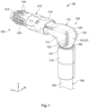
Figure 1 is a perspective view of an angled connector according to an embodiment; -
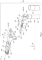
Figure 2 is an exploded perspective view of the angled connector ofFigure 1 ; -
Figure 3 is a perspective view of an angled shield of the angled connector ofFigure 1 ; -
Figure 4 is a perspective view of an angled dielectric of the angled connector ofFigure 1 ; -
Figure 5 is a perspective view of an inner ferrule of the angled connector ofFigure 1 ; -
Figure 6A is a perspective view of a cable of the angled connector ofFigure 1 connected to contacts of the angled connector; -
Figure 6B is a perspective view of the cable, the angled dielectric, and the inner ferrule of the angled connector ofFigure 1 with a dielectric cover of the angled dielectric in an open dielectric position; -
Figure 6C is a perspective view of the cable and the angled dielectric ofFigure 6B with the dielectric cover in a closed dielectric position; -
Figure 6D is a perspective view of the cable with the angled dielectric in the angled shield ofFigure 3 , with a shield cover of the angled shield in an open shield position; -
Figure 6E is a perspective view of the cable in the angled shield ofFigure 6D with the shield cover in a closed shield position; -
Figure 6F is a perspective view of the cable in the angled shield with the shield cover in the closed shield position ofFigure 6E and with a braid of the cable disposed over a first shield section of the angled shield; -
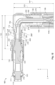
Figure 7 is a sectional side view of the angled connector ofFigure 1 ; -
Figure 8 is a sectional top view of the angled connector ofFigure 1 ; -
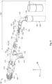
Figure 9 is an exploded perspective view of an angled connector according to another embodiment; -
Figure 10 is a perspective view of an inner ferrule of the angled connector ofFigure 9 ; -
Figure 11A is a perspective view of a cable and the inner ferrule of the angled connector ofFigure 9 ; -
Figure 11B is a perspective view of the cable and the inner ferrule ofFigure 11A with the inner ferrule in a bent position; -
Figure 11C is a perspective view of the cable with the inner ferrule ofFigure 11B in an angled shield, with a shield cover of the angled shield in an open shield position; -
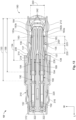
Figure 12 is a sectional side view of the angled connector ofFigure 9 ; and -
Figure 13 is a sectional top view of the angled connector ofFigure 9 . - An
angled connector 10 according to an embodiment, as shown inFigure 1 , includes anangled subassembly 100 and amating subassembly 300 connected to theangled subassembly 100. - The
angled subassembly 100, in the embodiment shown inFigures 1 ,2 ,7 , and8 , includes anangled shield 110, an angled dielectric 150 disposed in theangled shield 110, acable 180 disposed in theangled shield 110, acontact 190 electrically connected to thecable 180, aninner ferrule 200 disposed around thecable 180 within theangled shield 110, and anouter ferrule 210 disposed around thecable 180 and theangled shield 110. - As shown in
Figure 3 , theangled shield 110 has ashield body 112 extending from afirst end 114 to an oppositesecond end 116. Theangled shield 110 has afirst shield section 120 and asecond shield section 130 extending from thefirst shield section 120. - The
first shield section 120, as shown inFigure 3 , extends from thefirst end 114 of theshield body 112. Thefirst shield section 120 has afirst shield axis 122 extending centrally through thefirst shield section 120. In the shown embodiment, thefirst shield axis 122 extends along a vertical direction V. - The
second shield section 130 extends from thefirst shield section 120 to thesecond end 116 of theshield body 112, as shown inFigure 3 . Thesecond shield section 120 has asecond shield axis 132 extending centrally through thesecond shield section 120. In the shown embodiment, thesecond shield axis 132 extends along a longitudinal direction L perpendicular to the vertical direction V. - As shown in
Figure 3 , due to the direction of extension of thesecond shield axis 132 with respect to thefirst shield axis 122, thesecond shield section 130 extends at abend angle 140 with respect to thefirst shield section 120. In the shown embodiment, thebend angle 140 is 90° and thesecond shield section 130 extends perpendicularly with respect to thefirst shield section 120. In other embodiments, thebend angle 140 can be any angle greater than 90° and less than 180°, and thesecond shield section 130 can extend at angles between 90° and 180° with respect to thefirst shield section 120. In other embodiments, thebend angle 140 can be less than 90° or equal to 180°. - In the
first shield section 120, as shown inFigures 2 and3 , theangled shield 110 has ashield cover 124 attached to theshield body 112 at ashield hinge 128. Theshield cover 124 is pivotable with respect to theshield body 112 about theshield hinge 128 between an open shield position SO, shown inFigure 2 , and a closed shield position SC, as shown inFigure 3 . - In the embodiment shown in
Figures 2 and3 , theshield body 112 has atab 123 in thefirst shield section 120 and theshield cover 124 has arecess 126 extending into theshield cover 124. When theshield cover 124 is pivoted into the closed shield position SC, as shown inFigure 3 , thetab 123 enters therecess 126 and secures theshield cover 124 in the closed shield position SC. In the shown embodiment, theshield body 112 has twotabs 123 corresponding to tworecesses 126 of theshield cover 124. In other embodiments, theshield body 112 may have one or more than twotabs 123 and theshield cover 124 may have one or more than tworecesses 126, provided that the number oftabs 123 is equal to the number ofrecesses 126. - The
shield body 112, as shown inFigures 2 and3 , has ashield latch 127 extending from theshield body 112 in thefirst shield section 120. Theshield cover 124 has ashield catch 125 extending from theshield cover 124. When theshield cover 124 is pivoted into the closed shield position SC, as shown inFigure 3 , theshield catch 125 engages with theshield latch 127 to secure theshield cover 124 in the closed shield position SC. - In the embodiment shown in
Figures 2 and3 , theshield latch 127 is a tab that has an opening extending through the tab and theshield catch 125 is a protrusion that can engage with the opening; in this embodiment, theshield latch 127 elastically deflects under contact with theshield catch 125 as theshield cover 124 moves to the closed shield position SC, and elastically restores with theshield catch 125 positioned in theshield latch 127 when theshield cover 124 reaches the closed shield position SC. In other embodiments, theshield latch 127 and theshield catch 125 may be any other type of mechanical latches, such as hooks, that engage one another in the closed shield position SC. In the shown embodiment, theshield body 112 has twoshield latches 127 and theshield cover 124 has twoshield catches 125. In other embodiments, theshield body 112 may have one or more than twoshield latches 127 and theshield cover 124 may have one or more than twoshield catches 125, provided that the number ofshield latches 127 is equal to the number ofshield catches 125. - In the
second shield section 130, as shown inFigure 3 ,7 , and8 , theangled shield 110 has atransition portion 134 in which a dimension of aninterior space 138 of thesecond shield section 130, shown inFigures 7 and8 , is decreased along the vertical direction V and a width direction W perpendicular to the longitudinal direction L and the vertical direction V. In the shown embodiment, thetransition portion 134 is formed by a plurality ofspring members 136 extending into theinterior space 138 of thesecond shield section 130 opposite one another in the vertical direction V. In the shown embodiment, twospring members 136 are positioned opposite one another in the vertical direction V and twospring members 136 are positioned opposite one another in the width direction W. In other embodiments, thetransition portion 134 may include three or less or five ormore spring members 136. Each of thespring members 136 is resiliently deflectable and has acontact bend 137 at a maximum protrusion into theinterior space 138. - The
angled shield 110 is formed of a conductive material, such as aluminum, and in an embodiment is monolithically formed in a single piece with at least theshield body 112, thefirst section 120, thesecond section 130, and theshield cover 124. Theangled shield 110 may be formed by stamping and bending from a sheet of conductive material. In other embodiments, theangled shield 110 may be formed from a plurality of separate elements attached together. - The angled dielectric 150, as shown in
Figure 4 , has adielectric body 152 extending from afirst end 154 to an oppositesecond end 156. As shown inFigure 4 , the angled dielectric 150 has a firstdielectric section 160 and a seconddielectric section 170 extending from the firstdielectric section 160. - The first
dielectric section 160, as shown inFigure 4 , extends from thefirst end 154 of thedielectric body 152. The firstdielectric section 160 has a firstdielectric axis 162 extending centrally through the firstdielectric section 160. In the shown embodiment, the firstdielectric axis 162 extends along the vertical direction V. - The
second dielectric section 170 extends from the firstdielectric section 160 to thesecond end 156 of thedielectric body 152, as shown inFigure 4 . Thesecond dielectric section 170 has a seconddielectric axis 172 extending centrally through thesecond dielectric section 170. In the shown embodiment, the seconddielectric axis 172 extends along the longitudinal direction L. - As shown in
Figure 4 , due to the direction of extension of the seconddielectric axis 172 with respect to the firstdielectric axis 162, thesecond dielectric section 170 extends at thebend angle 140 with respect to the firstdielectric section 160. Thebend angle 140 of thesecond dielectric section 170 with respect to the firstdielectric section 160 is the same as thebend angle 140 of thesecond shield section 130 with respect to thefirst shield section 120; thebend angle 140 of thesecond dielectric section 170 with respect to the firstdielectric section 160 is greater than or equal to 90° and less than 180°. In another embodiment, thebend angle 140 can be less than 90° or equal to 180°. - In the first
dielectric section 160, as shown inFigure 4 , theangled dielectric 150 has adielectric cover 164 attached to thedielectric body 152 at adielectric hinge 168. Thedielectric cover 164 is pivotable with respect to thedielectric body 152 about thedielectric hinge 168 between an open dielectric position DO, shown inFigures 4 and6B , and a closed dielectric position DC, shown inFigures 2 and6C . - In the embodiment shown in
Figure 4 , thedielectric body 152 has adielectric catch 158 in the firstdielectric section 160 and thedielectric cover 164 has adielectric latch 166. When thedielectric cover 164 is pivoted into the closed dielectric position DC, thedielectric latch 166 engages with thedielectric catch 158 and secures thedielectric cover 164 in the closed dielectric position DC. In the shown embodiment, thedielectric catch 158 is a recess and thedielectric latch 166 is a protrusion complementary to the recess of thedielectric catch 158. In other embodiments, thedielectric catch 158 may be a protrusion and thedielectric latch 166 may be a recess complementary to the protrusion of thedielectric catch 158, or thedielectric catch 158 and thedielectric latch 166 may be any other elements capable of engaging with one another to secure thedielectric cover 164 in the closed dielectric position DC. In another embodiment, thedielectric catch 158 and thedielectric latch 166 may be omitted. - The
angled dielectric 150 is a dielectric material, such as a plastic, and in an embodiment is monolithically formed in a single piece with at least thedielectric body 152, the firstdielectric section 160, thesecond dielectric section 170, and thedielectric cover 164; in this embodiment, thedielectric hinge 168 is a film hinge. In other embodiments, theangled dielectric 150 may be formed from a plurality of separate elements attached together. - The
cable 180, as shown inFigures 2 and6A , has awire 183, afoil 184 disposed around thewire 183, abraid 185 disposed around thefoil 184, and acable insulation 186 disposed around thebraid 185. - In the shown embodiment, the
cable 180 includes a twisted pair ofwires 183, with each of thewires 183 having aconductor 183a and awire insulation 183b disposed around theconductor 183a. In the twisted pair embodiment, thewires 183 are twisted around one another within thefoil 184 with thewire insulation 183b of each of thewires 183 in abutment with one another. In another embodiment, thecable 180 includes a pair ofwires 183 extending parallel to one another, each of thewires 183 having theconductor 183a and thewire insulation 183b. In another embodiment, thecable 180 may have onewire 183 with oneconductor 183a surrounded by onewire insulation 183b. - The
foil 184 is disposed around thewires 183 orwire 183 in abutment with thewire insulation 183b, as shown inFigures 2 and6A . Thefoil 184 is formed of a conductive material. Thebraid 185 is disposed around and in abutment with thefoil 184; thebraid 185 is formed of a conductive material. Thecable insulation 186, formed of an insulative material, is disposed around and in abutment with thebraid 185. - The
contact 190, as shown inFigures 2 and6A , has amating portion 192 and aconnection portion 194 at an end opposite themating portion 192. Thecontact 190 is formed of a conductive material. In the shown embodiment, themating portion 192 is a receptacle for a pin; in other embodiments, themating portion 192 could be a pin or any other type of contact element capable of mating with another contact element. In the shown embodiment, theconnection portion 194 is a crimping portion capable of being crimped to a conductor. In other embodiments, theconnection portion 194 could be a flat element capable of being welded to a conductor, or any other type of element capable of mechanically and electrically connecting thecontact 190 to a conductor. Theangled subassembly 100 has twocontacts 190 in the shown embodiment. The number ofcontacts 190 corresponds to the number ofwires 183 of thecable 180; theangled subassembly 100 may alternatively have onecontact 190 for an embodiment of thecable 180 having onewire 183. - The
inner ferrule 200, as shown inFigure 5 , has a base 210 extending from afirst end 212 to asecond end 214 along the longitudinal direction L. Theinner ferrule 200 has afirst crimp section 220 at thefirst end 212 and asecond crimp section 230 at thesecond end 214; thesecond crimp section 230 is connected to thefirst crimp section 220 by thebase 210. Thefirst crimp section 220 has a pair offirst crimp wings 222 extending from thebase 210 and positioned opposite one another in the width direction W. Thesecond crimp section 220 has a pair ofsecond crimp wings 232 extending from thebase 210 and positioned opposite one another in the width direction W. - In the
second crimp section 230, as shown inFigure 5 , thebase 210 has afan protrusion 236 extending in the vertical direction V at least partially between thesecond crimp wings 232. Thefan protrusion 236 has an approximately triangular shape, with a narrower portion on the base 210 adjacent to thefirst crimp section 220 and a wider portion at thesecond end 214 of thebase 210. Thefan protrusion 236 and thesecond crimp wings 232 form a flaredshape 238 of thesecond crimp section 230 opening toward thesecond end 214 of thebase 210. In another embodiment, thefan protrusion 236 can be omitted, and thesecond crimp section 230 can extend straight from thefirst crimp section 220 along the longitudinal direction L. - In the embodiment shown in
Figure 5 , thefirst end 212 of thebase 210 is connected to acarrier strip 240. A plurality ofinner ferrules 200 can be connected to thecarrier strip 240 to move theinner ferrules 200 during production or for other applications and, prior to use of theinner ferrule 200 as described below, theinner ferrule 200 is separated from thecarrier strip 240 at thefirst end 212 of thebase 210. - The
inner ferrule 200 is formed of a conductive material, such as aluminum or copper, and in an embodiment is monolithically formed in a single piece with at least the base 210, thefirst crimp section 220, and thesecond crimp section 230. In the shown embodiment, theinner ferrule 200 is also monolithically formed with thecarrier strip 240 prior to separation from thecarrier strip 240. Theinner ferrule 200 may be formed by stamping and bending from a sheet of conductive material. In other embodiments, theinner ferrule 200 may be formed from a plurality of separate elements attached together. In another embodiment, theinner ferrule 200 may have a plurality offirst crimp sections 220 and a plurality ofsecond crimp sections 230 to connect to a plurality of wires. - The
outer ferrule 210, as shown in the embodiment ofFigures 1 and2 , is an approximately cylindrical element formed of a conductive material. In an embodiment, theouter ferrule 210 is formed from bending or rolling a sheet of conductive material. - The
mating subassembly 300, as shown inFigures 1 and2 , includes amating shield 310 and amating dielectric 320 disposed within themating shield 310. Themating shield 310, formed of a conductive material, extends from afirst end 312 to an oppositesecond end 314 along the longitudinal direction L. Themating shield 310 has a plurality of contact springs 316 disposed adjacent to thefirst end 312. In an embodiment, themating shield 310 is monolithically formed in a single piece. Themating dielectric 320 is formed of a dielectric material and, as shown inFigure 8 , has a plurality ofcontact receiving passageways 322 extending through themating dielectric 320 along the longitudinal direction L. Themating dielectric 320 can alternatively have one or more than twocontact receiving passageways 322; the number ofcontact receiving passageways 322 corresponds to the number ofwires 183 of thecable 180 and the number ofcontacts 190. - The assembly of the
angled connector 10 will now be described primarily with respect toFigures 6A-6F . - In a first step, shown in
Figure 6A , thecable insulation 186, thebraid 185, and thefoil 184 are stripped to expose thewires 183. For each of thewires 183, a portion of thewire insulation 183b is stripped to expose a portion of theconductor 183a. Theconnection portion 194 of each of thecontacts 190 is electrically and mechanically connected to one of the exposedconductors 183a. In the embodiment shown inFigure 6A , theconnections portions 194 are crimped to theconductors 183a. - In a next step, shown in
Figure 6B , thecable 180 is inserted into and through theangled dielectric 150 with thedielectric cover 164 in the open dielectric position DO. In the step shown inFigure 6B , thecable 180 extends though theangled dielectric 150 along the seconddielectric axis 172 shown inFigure 4 . - The
inner ferrule 200, in the step shown inFigure 6B , is moved into a position in which it is disposed around thecable 180. Thefirst crimp section 220 is disposed around thefoil 184 and thewires 183 and thefirst crimp wings 222 are crimped around thefoil 184 and thewires 183. Thefirst crimp wings 222 in thefirst crimp section 220 press thefoil 184 against thewires 183 to hold thefoil 184 in place and electrically connect theinner ferrule 200 to thefoil 184. Thesecond crimp section 230 is disposed around thewires 183 and thesecond crimp wings 232 are crimped around thewires 183. The crimpedsecond crimp wings 232 and thefan protrusion 236 are positioned at least partially between thewires 183 in the width direction W. Thesecond crimp wings 232 press against thewire insulation 183b of thewires 183 and, with thefan protrusion 236, form the flaredshape 238. Thewires 183, as shown inFigure 8 , are positioned adjacent to one another in thefirst crimp section 220, and the flaredshape 238 holds thewires 183 at apitch 189 separated from one another at thesecond end 214 of theinner ferrule 200. In another embodiment, thesecond crimp wings 232 and thefan protrusion 236 could position thewires 183 parallel to each other through all of thesecond crimp section 230 and thewires 183 could transition outwards to thepitch 189 prior to reaching thesecond crimp section 230 along the longitudinal direction L, in the space between thefirst crimp section 220 and thesecond crimp section 230. Thepitch 189 is predetermined and is chosen for optimal impedance control. - In a next step, shown in
Figure 6C , thecable 180 is bent within theangled dielectric 150. When thecable 180 is bent, thecable 180 has afirst portion 187 and asecond portion 188 extending at thebend angle 140 with respect to thefirst portion 187. Thefirst portion 187 is disposed in the firstdielectric section 160 and thesecond portion 188 is disposed in thesecond dielectric section 170. As shown inFigure 6C , theinner ferrule 200 is disposed adjacent to thesecond dielectric section 170. - With the
cable 180 fully inserted through theangled dielectric 150 and bent into the shape described above and shown inFigure 6C , thedielectric cover 164 is moved from the open dielectric position DO to the closed dielectric position DC shown inFigure 6C . In an embodiment, thedielectric catch 158 engages thedielectric latch 166 to secure thedielectric cover 164 in the closed dielectric position DC. In another embodiment, in lieu of or in addition to thedielectric catch 158 and thedielectric latch 166, thedielectric cover 164 is secured to thedielectric body 152 in the closed dielectric position DC by plastic welding of thedielectric cover 164 to thedielectric body 152. In another embodiment, theangled dielectric 150 does not have thedielectric cover 164 pivotable with respect to thedielectric body 152, but rather is overmolded in a single piece over thefoil 184 of thecable 180 in the position shown inFigure 6C . - The
angled dielectric 150 in the position shown inFigure 6C , due to the structure and thebend angle 140 of the firstdielectric section 160 with respect to thesecond dielectric section 170, secures thecable 180 in the position shown inFigure 6C with thefirst portion 187 at thesame bend angle 140 with respect to thesecond portion 188. In the shown embodiment, thecable 180 is inserted into theangled dielectric 150 to be bent and held with thecontacts 190 already connected to thewires 183, and theinner ferrule 200 is crimped to thecable 180 after thecable 180 is inserted through theangled dielectric 150. In another embodiment, thecable 180 can be inserted into theangled dielectric 150, bent, and held by theangled dielectric 150 prior to connecting thecontacts 190 with thewires 183. - In a step shown in
Figure 6D , thecable 180 bent and held by theangled dielectric 150 is inserted into theangled shield 110 with theshield cover 124 in the open shield position SO. In the position shown inFigure 6D , thebraid 185 is flared outwards from thecable 180. - The
shield cover 124 is then moved from the open shield position SO shown inFigure 6D to the closed shield position SC shown inFigure 6E , enclosing thecable 180 in theshield body 112. In the shown embodiment, thetab 123 is disposed in therecess 126 to secure theshield cover 124 in the closed shield position SC. As shown inFigure 3 and described above, theshield catch 125 engages with theshield latch 127 to secure theshield cover 124 in the closed shield position SC. In other embodiments, including thetab 123 and therecess 126 or omitting thetab 123 and therecess 126, and in addition to or in lieu of engagement of theshield catch 125 with theshield latch 127, theshield cover 124 can be welded or joined by forming to theshield body 112 to secure theshield cover 124 in the closed shield position SC. - With the
shield cover 124 in the closed shield position SC shown inFigure 6E , thebraid 185 is dressed or folded over thefirst shield section 120 of theangled shield 110, as shown inFigure 6F . Theouter ferrule 210 is then positioned over the exposed portion of thebraid 185 and a portion of thecable insulation 186 and crimped over thebraid 185, thefirst shield section 120, and thecable insulation 186, as shown inFigures 1 and7 . - In the embodiment shown in
Figures 6D-6F , themating subassembly 300 is already connected to theangled shield 110 when theangled dielectric 150 and thecable 180 are inserted into theangled shield 110. As shown inFigures 7 and8 , thesecond end 116 of theangled shield 110 at thesecond shield section 130 is inserted into thesecond end 314 of themating shield 310 and disposed in themating shield 310. Theangled shield 110 is mechanically and electrically connected to themating shield 310 through thesecond shield section 130. Themating dielectric 320 is disposed within theinterior space 138 of thesecond shield section 130, as shown inFigures 7 and8 . Themating dielectric 320 extends from a position adjacent to thetransition portion 134 and out of thesecond shield section 130 along the longitudinal direction L. In another embodiment, themating subassembly 300 can be connected to theangled shield 110 after theangled dielectric 150 and thecable 180 are inserted into theangled shield 110. - The
angled connector 10 is shown in a fully assembled state inFigures 1 ,7 , and8 in which thecable 180 is disposed and held within theangled shield 110 and theangled dielectric 150. - As shown in
Figure 7 , thefirst portion 187 of thecable 180 is positioned in thefirst shield section 120 of theangled shield 110 and in the firstdielectric section 160 of theangled dielectric 150. Thefoil 184 is disposed around thewires 183 in thefirst portion 187 and is held in abutment against thewire insulation 183b of thewires 183. Thebraid 185 in thefirst portion 187 is crimped to thefirst shield section 120 by theouter ferrule 210 and is disposed between thefirst shield section 120 and theouter ferrule 210; in an embodiment, thefirst shield section 120 provides a support for crimping of theouter ferrule 210 around thebraid 185 and thecable 180 that prevents the crimping of theouter ferrule 210 from damaging thefoil 194 or thewires 183. - The
second portion 188 of thecable 180, as shown inFigures 7 and8 , is positioned in thesecond shield section 130 of theangled shield 110 and in thesecond dielectric section 170 of theangled dielectric 150. Thefoil 184 is disposed around thewires 183 in thesecond portion 188 and is held in abutment against thewire insulation 183b of thewires 183 by thefirst crimp section 220 of theinner ferrule 200. Thefirst crimp section 220 and thesecond crimp section 230 are disposed in thesecond shield section 130. Thewires 183 and thefoil 184 are each disposed in thefirst portion 187 and thesecond portion 188 of thecable 180. - The
first crimp section 220 of theinner ferrule 200 is electrically and mechanically connected to thefoil 184 by the crimping of thefirst crimp wings 222. As shown inFigures 7 and8 , when thecable 180 with theinner ferrule 200 crimped to thecable 180 is positioned within theinterior space 138 of thesecond shield section 130, thespring members 136 extending into theinterior space 138 contact theinner ferrule 200. Thecontact bend 137 of each of thespring members 136 contacts thesecond crimp section 230 of theinner ferrule 200 and thespring members 136 resiliently deflect to apply a pressure maintaining a contact of thespring members 136 with thesecond crimp section 230. Thespring members 136 form and maintain an electrical connection between theangled shield 110 and theinner ferrule 200. Theinner ferrule 200 electrically connects theangled shield 110 to thefoil 184 through the crimping of thefirst crimp section 220. - As shown in
Figure 8 , each of thecontacts 190 is positioned and held in one of thecontact receiving passageways 322 of themating dielectric 320, within thesecond shield section 130 of theangled shield 110. Theconductors 183a of thewires 183 electrically and mechanically connected to theconnection portions 194 of thecontacts 190 are disposed within themating dielectric 320 and themating portions 192 of thecontacts 190 opposite theconnection portions 194 are disposed adjacent to thefirst end 312 of themating shield 310. - In the fully assembled state shown in
Figures 1 ,7 , and8 , thefoil 184 of thecable 180, theangled shield 110, thebraid 185, theinner ferrule 200, theouter ferrule 210, and themating shield 310 are electrically connected. Theconductors 183a of thewires 183 are electrically connected to thecontacts 190 and are electrically isolated from thefoil 184, theangled shield 110, thebraid 185, theinner ferrule 200, and themating shield 310 by thewire insulations 183b and themating dielectric 320. When theangled connector 10 is connected with a mating connector, the contact springs 316 of themating shield 310 resiliently abut and electrically connect with a shield of the mating connector, and thecontacts 190 mate and electrically connect with contacts of the mating connector. - In the
angled connector 10, thecable 180 extends through a bend with thefirst portion 187 held at thebend angle 140 with respect to thesecond portion 188 by theangled shield 110 and theangled dielectric 150. By having the bend in thecable 180 itself, thefoil 184 can remain over a longer portion of thecable 180 in theangled connector 10, allowing for a high degree of impedance control and improved shielding performance. Thefirst crimp section 220 of theinner ferrule 200 crimped over thefoil 184 maintains a tight fit of the wire orwires 183 within theangled shield 110 and a tight wrap of thefoil 184 around thewires 183 in thesecond portion 188. The contact of thesecond crimp section 230 with theangled shield 110 at thespring members 136 forms a reliable electrical connection between theangled shield 110 and thefoil 184 through theinner ferrule 200, further aiding in the high degree of impedance control and improved shielding performance. - The
foil 184 extending over a large portion of thecable 180 and through the bend also avoids the crimping of theouter ferrule 210 having a significant impact on the impedance control; theouter ferrule 210 can be crimped as tight as necessary for mechanical robustness and as described above, can bear on thefirst shield section 120 instead of potentially damaging thefoil 184. Simple designs of thecontact 190 can be used with theangled connector 10, saving on component cost and decreasing the complexity of assembly. - In the shown embodiment, the
angled dielectric 150 maintains a tight fit of the wire orwires 183 within theangled shield 110 and a tight wrap of thefoil 184 around thewires 183 in thefirst portion 187 and thesecond portion 188. In another embodiment, theangled dielectric 150 can be omitted. In an embodiment omitting theangled dielectric 150, the other elements of theangled connector 10 are still arranged as described above; thecable 180 extends through theangled shield 110 with thefirst portion 187 and thesecond portion 188 still at thebend angle 140, and theinner ferrule 200 is relied upon to maintain the tightness of thewires 183 with each other and the tight wrap of thefoil 184. - The
angled connector 10 in the shown embodiment holds thefirst portion 187 of thecable 180 with respect to thesecond portion 188 of thecable 180 on the opposite side of the bend at thebend angle 140 of 90°. In other embodiments, thebend angle 140 can be any angle greater than 90° and less than 180°, or any angle less than 90° or equal to 180°. Thecable 180 in the shown embodiment also has a particular rotational position with respect to thecontacts 190 about a rotational axis of the longitudinal direction L. Theangled connector 10 is not limited to the rotational position of the shown embodiment, and thecable 180 could be arranged and held by theangled subassembly 100 at any rotational position about the longitudinal axis L with respect to thecontacts 190. - An angled connector 10' according to another embodiment, as shown in
Figure 9 , includes an angled subassembly 100' and amating subassembly 300 connected to the angled subassembly 100'. Like reference numbers refer to like elements with the embodiment of theangled connector 10 described above with respect toFigures 1-8 , and primarily the differences of the embodiment of the angled connector 10' will be described herein with reference toFigures 9-13 . - In the angled subassembly 100', as shown in
Figure 9 , theangled shield 110, thecable 180, thecontact 190, and theouter ferrule 210 are the same as shown and described in detail above with respect to theangled subassembly 100 ofFigures 1-8 . Theangled dielectric 150 is omitted in the embodiment of the angled subassembly 100' and the differences of an inner ferrule 200' of the angled subassembly 100' will be described in greater detail below. - The inner ferrule 200', as shown in
Figure 10 , has a base 210 extending from afirst end 212 to asecond end 214 along the longitudinal direction L. The inner ferrule 200' has athird crimp section 240 at thefirst end 212, asecond crimp section 230 at thesecond end 214, and afirst crimp section 220 between thethird crimp section 240 and thesecond crimp section 230; thethird crimp section 240 is connected to thefirst crimp section 220 and thesecond crimp section 230 by thebase 210. Thefirst crimp section 220 has a pair offirst crimp wings 222 extending from thebase 210 and positioned opposite one another in the width direction W. Thesecond crimp section 220 has a pair ofsecond crimp wings 232 extending from thebase 210 and positioned opposite one another in the width direction W. Thethird crimp section 240 has a pair ofthird crimp wings 242 extending from thebase 210 and positioned opposite one another in the width direction W. - As shown in
Figure 10 , thethird crimp section 240 is separated from thefirst crimp section 220 and thesecond crimp section 230 by abend region 216 of thebase 210. Thebend region 216 has aweakening element 218 that lessens a force required to bend thebend region 216. In the shown embodiment, the weakeningelement 218 is a thinning of the material of the base 210 in the vertical direction V; the thinning can be accomplished by removal of material of the base 210 or by formation of theweakening element 218 with the thinner dimension. In other embodiments, the weakeningelement 218 can be any other structure, such as variously arranged openings in thebase 210, that lessen the force required to bend thebend region 216. The weakeningelement 218 could also be omitted if thebend region 216 can be adequately bent without a weakening element. - As similarly described in the embodiment of
Figure 5 , in thesecond crimp section 230, as shown inFigure 10 , thebase 210 has afan protrusion 236 extending in the vertical direction V at least partially between thesecond crimp wings 232. Thefan protrusion 236 has an approximately triangular shape, with a narrower portion on the base 210 adjacent to thefirst crimp section 220 and a wider portion at thesecond end 214 of thebase 210. Thefan protrusion 236 and thesecond crimp wings 232 form a flaredshape 238 of thesecond crimp section 230 opening toward thesecond end 214 of thebase 210. In another embodiment, thesecond crimp wings 232 and thefan protrusion 236 could position thewires 183 parallel to each other through all of thesecond crimp section 230 and thewires 183 could transition outwards to thepitch 189 prior to reaching thesecond crimp section 230 along the longitudinal direction L, in the space between thefirst crimp section 220 and thesecond crimp section 230. - In the embodiment shown in
Figure 10 , thefirst end 212 of thebase 210 is connected to acarrier strip 240. A plurality of inner ferrules 200' can be connected to thecarrier strip 240 to move the inner ferrules 200' during production or for other applications and, prior to use of the inner ferrule 200' as described below, the inner ferrule 200' is separated from thecarrier strip 240 at thefirst end 212 of thebase 210. - The inner ferrule 200' is formed of a conductive material, such as aluminum or copper, and in an embodiment is monolithically formed in a single piece with at least the base 210, the
first crimp section 220, thesecond crimp section 230, and thethird crimp section 240. In the shown embodiment, the inner ferrule 200' is also monolithically formed with thecarrier strip 240 prior to separation from thecarrier strip 240. The inner ferrule 200' may be formed by stamping and bending from a sheet of conductive material. In other embodiments, the inner ferrule 200' may be formed from a plurality of separate elements attached together. - The assembly of the angled connector 10' will now be described primarily with respect to
Figures 11A-11C . Only the differences from the assembly shown and described inFigures 6A-6F will be described in detail herein. - Following the step shown in
Figure 6A , the inner ferrule 200' is moved into a position in which it is disposed around thecable 180, as shown inFigure 11A . Thefirst crimp section 220 and thesecond crimp section 230 are positioned on thecable 180 and crimped as described above with respect toFigure 6B . Thethird crimp section 140 is disposed around thefoil 184 and thewires 183 at a position spaced apart from thefirst crimp section 220 and thesecond crimp section 230 along the longitudinal direction L. In the state shown inFigure 11A , thefirst crimp section 220 and thesecond crimp section 230 are crimped, while thethird crimp wings 242 of thethird crimp section 240 remain uncrimped. - In a next step, as shown in
Figure 11B , the inner ferrule 200' is bent at thebend region 216 of thebase 210. Thebend region 216 is bent until thethird crimp section 240 extends at thebend angle 140 described above with respect to thefirst crimp section 220 and thesecond crimp section 230. With thethird crimp section 240 positioned at thebend angle 140 as shown inFigure 11B , thethird crimp wings 242 of thethird crimp section 240 are crimped. Thethird crimp wings 242 press thefoil 184 against thewires 183 to hold thefoil 184 in place and electrically connect the inner ferrule 200' to thefoil 184. The bending and crimping of thethird crimp section 240 bends thecable 180 to thebend angle 140. In another embodiment, thethird crimp section 240 can be crimped before thebend region 216 is bent and/or crimped such that thethird crimp wings 242 do not primarily hold thefoil 184 in place and electrically connect the inner ferrule 200' to thefoil 184, but rather provide rough positioning and strain relief. - Following the bending of the inner ferrule 220' and the crimping of the
third crimp section 240, thecable 180 and the crimped inner ferrule 200' are inserted into theangled shield 110 with the shield cover in the open shield position SO as shown inFigure 11C . In the position shown inFigure 11C , thebraid 185 is flared outwards from thecable 180. The assembly of the angled connector 10' is then completed in the same manner as described above with respect toFigures 6E and 6F . - The angled connector 10' is shown in a fully assembled state in
Figures 12 and13 in which thecable 180 is disposed and held within theangled shield 110. Only the position of the elements of the inner ferrule 200' will be described in detail with respect toFigures 12 and13 ; the positioning and function of the other elements of the angled connector 10' is the same as described above with respect toFigures 7 and8 . - As shown in
Figure 12 , thefoil 184 is disposed around thewires 183 in thefirst portion 187 and thesecond portion 188 of thecable 180 and is held in abutment against thewire insulation 183b of thewires 183 by thefirst crimp section 220 and thethird crimp section 240 of the inner ferrule 200'. Thefirst crimp section 220 and thesecond crimp section 230 are disposed in thesecond shield section 130. Thethird crimp section 240 is disposed in thefirst shield section 120. - The
first crimp section 220 and thethird crimp section 240 of the inner ferrule 200' are electrically and mechanically connected to thefoil 184 by the crimping of thefirst crimp wings 222 and thethird crimp wings 242. As shown inFigures 12 and13 , when thecable 180 with the inner ferrule 200' crimped to thecable 180 is positioned within theinterior space 138 of thesecond shield section 130, thespring members 136 extending into theinterior space 138 contact the inner ferrule 200'. Thecontact bend 137 of each of thespring members 136 contacts thesecond crimp section 230 of the inner ferrule 200' and thespring members 136 resiliently deflect to apply a pressure maintaining an abutment of thespring members 136 with thesecond crimp section 230. Thespring members 136 form and maintain an electrical connection between theangled shield 110 and the inner ferrule 200'. The inner ferrule 200' electrically connects theangled shield 110 to thefoil 184 through the crimping of thefirst crimp section 220 and thethird crimp section 240. - In the angled connector 10', the
first crimp section 220 and thethird crimp section 240 of the inner ferrule 200' crimped over thefoil 184 maintain a tight fit of the wire orwires 183 within theangled shield 110 and a tight wrap of thefoil 184 around thewires 183 in thefirst portion 187 and thesecond portion 188. Thebend region 216 of the inner ferrule 200' positions thecable 180 at thebend angle 140 to extend through theangled shield 110. The contact of thesecond crimp section 230 with theangled shield 110 at thespring members 136 forms a reliable electrical connection between theangled shield 110 and thefoil 184 through the inner ferrule 200', aiding in the high degree of impedance control and improved shielding performance. - Various aspects and embodiments of the invention are defined in the following numbered clauses:
-
Clause 1. An angled subassembly (100) of an angled connector (10), comprising:- an angled shield (110) having a first shield section (120) and a second shield section (130) extending at a bend angle (140) with respect to the first shield section (120);
- a cable (180) disposed in the first shield section (120) and the second shield section (130) of the angled shield (110), the cable (180) having a wire (183) and a foil (184) disposed around the wire (183); and
- an inner ferrule (200) disposed around the cable (180) within the angled shield (110) and electrically connecting the foil (184) to the angled shield (110).
- Clause 2. The angled subassembly (100) of
Clause 1, wherein the inner ferrule (200) has a first crimp section (220) and a second crimp section (230) connected to the first crimp section (220) by a base (210), the first crimp section (220) is disposed around the foil (184) and the wire (183) and the second crimp section (230) is disposed around the wire (183). - Clause 3. The angled subassembly (100) of Clause 2, wherein the wire (183) is one of a pair of wires (183) disposed within the foil (184) of the cable (180), the base (210) has a fan protrusion (236) in the second crimp section (230) extending partially between the pair of wires (183).
- Clause 4. The angled subassembly (100) of Clause 3, wherein the wires (183) are positioned adjacent to one another in the first crimp section (220), the second crimp section (230) has a flared shape (238) that holds the wires (183) at a pitch (189) separated from one another at an end (214) of inner ferrule (200).
- Clause 5. The angled subassembly (100) of Clause 2, wherein the first crimp section (220) and the second crimp section (230) are disposed in the second shield section (130) of the angled shield (110).
- Clause 6. The angled subassembly (100) of Clause 5, wherein the inner ferrule (200) has a third crimp section (240) connected to the first crimp section (220) and the second crimp section (230) by the base (210), the third crimp section (240) is disposed around the foil (184) and the wire (183).
- Clause 7. The angled subassembly (100) of Clause 6, wherein the third crimp section (240) is separated from the first crimp section (220) and the second crimp section (230) by a bend region (216) of the base (210), the third crimp section (240) extends at the bend angle (140) with respect to the first crimp section (220) and the second crimp section (230), the third crimp section (240) is disposed in the first shield section (120) of the angled shield (110).
- Clause 8. The angled subassembly (100) of
Clause 1, wherein the angled shield (110) has a plurality of spring members (136) in the second shield section (130) resiliently contacting the inner ferrule (200). - Clause 9. The angled subassembly (100) of
Clause 1, wherein the angled shield (110) has a shield body (112) and a shield cover (124) attached to the shield body (112), the shield cover (124) is pivotable with respect to the shield body (112) between an open shield position (SO) in which the cable (180) is insertable into the shield body (112) and a closed shield position (SC) enclosing the cable (180) in the shield body (112). -
Clause 10. The angled subassembly (100) ofClause 1, further comprising an angled dielectric (150) disposed within the angled shield (110), the wire (183) and the foil (184) of the cable (180) extend through the angled dielectric (150), the angled dielectric (150) has a first dielectric section (160) and a second dielectric section (170) extending at the bend angle (140) with respect to the first dielectric section (160), the inner ferrule (200) is disposed adjacent to the second dielectric section (170). - Clause 11. An angled connector (10), comprising:
- an angled subassembly (100) including an angled shield (110), a cable (180) disposed in the angled shield (110), and an inner ferrule (200) disposed around the cable (180) within the angled shield (110), the angled shield (110) has a first shield section (120) and a second shield section (130) extending at a bend angle (140) with respect to the first shield section (120), the cable (180) is disposed in the first shield section (120) and the second shield section (130) and has a wire (183) and a foil (184) disposed around the wire (183), the inner ferrule (200) electrically connects the foil (184) to the angled shield (110); and
- a mating subassembly (300) connected to the angled subassembly (100).
- Clause 12. The angled connector (10) of Clause 11, wherein the mating subassembly (300) has a mating shield (310) electrically connected to the angled shield (110) and a mating dielectric (320) disposed within the mating shield (310).
-
Clause 13. A method of assembling an angled subassembly (100) of an angled connector (10), comprising:- providing a cable (180) having a wire (183) and a foil (184) disposed around the wire (183);
- crimping an inner ferrule (200) around the cable (180); and
- inserting the cable (180) with the inner ferrule (200) crimped around the cable (180) into an angled shield (110) having a first shield section (120) and a second shield section (130) extending at a bend angle (140) with respect to the first shield section (120), the cable (180) is disposed in the first shield section (120) and the second shield section (130), the inner ferrule (200) electrically connects the foil (184) to the angled shield (110).
- Clause 14. The method of
Clause 13, wherein the angled shield (110) has a shield body (112) and a shield cover (124) attached to the shield body (112), the cable (180) with the inner ferrule (200) is inserted into the shield body (112) with the shield cover (124) in an open shield position (SO), and further comprising pivoting the shield cover (124) with respect to the shield body (112) into a closed shield position (SC). - Clause 15. The method of
Clause 13, further comprising bending the inner ferrule (200) to the bend angle (140) prior to inserting the cable (180) with the inner ferrule (200) into the angled shield (110).
Claims (14)
- An angled subassembly (100) of an angled connector (10), comprising:an angled shield (110) having a first shield section (120) and a second shield section (130) extending at a bend angle (140) with respect to the first shield section (120);a cable (180) disposed in the first shield section (120) and the second shield section (130) of the angled shield (110), the cable (180) having a wire (183) and a foil (184) disposed around the wire (183); andan inner ferrule (200) disposed around the cable (180) within the angled shield (110) and electrically connecting the foil (184) to the angled shield (110),wherein the angled shield (110) has a plurality of spring members (136) in the second shield section (130) resiliently contacting the inner ferrule (200).
- The angled subassembly (100) of claim 1, wherein the inner ferrule (200) has a first crimp section (220) and a second crimp section (230) connected to the first crimp section (220) by a base (210), the first crimp section (220) is disposed around the foil (184) and the wire (183) and the second crimp section (230) is disposed around the wire (183).
- The angled subassembly (100) of claim 2, wherein the wire (183) is one of a pair of wires (183) disposed within the foil (184) of the cable (180), the base (210) has a fan protrusion (236) in the second crimp section (230) extending partially between the pair of wires (183).
- The angled subassembly (100) of claim 3, wherein the wires (183) are positioned adjacent to one another in the first crimp section (220), the second crimp section (230) has a flared shape (238) that holds the wires (183) at a pitch (189) separated from one another at an end (214) of inner ferrule (200).
- The angled subassembly (100) of claim 2, wherein the first crimp section (220) and the second crimp section (230) are disposed in the second shield section (130) of the angled shield (110).
- The angled subassembly (100) of claim 5, wherein the inner ferrule (200) has a third crimp section (240) connected to the first crimp section (220) and the second crimp section (230) by the base (210), the third crimp section (240) is disposed around the foil (184) and the wire (183).
- The angled subassembly (100) of claim 6, wherein the third crimp section (240) is separated from the first crimp section (220) and the second crimp section (230) by a bend region (216) of the base (210), the third crimp section (240) extends at the bend angle (140) with respect to the first crimp section (220) and the second crimp section (230), the third crimp section (240) is disposed in the first shield section (120) of the angled shield (110).
- The angled subassembly (100) of claim 1, wherein the angled shield (110) has a shield body (112) and a shield cover (124) attached to the shield body (112), the shield cover (124) is pivotable with respect to the shield body (112) between an open shield position (SO) in which the cable (180) is insertable into the shield body (112) and a closed shield position (SC) enclosing the cable (180) in the shield body (112).
- The angled subassembly (100) of claim 1, further comprising an angled dielectric (150) disposed within the angled shield (110), the wire (183) and the foil (184) of the cable (180) extend through the angled dielectric (150), the angled dielectric (150) has a first dielectric section (160) and a second dielectric section (170) extending at the bend angle (140) with respect to the first dielectric section (160), the inner ferrule (200) is disposed adjacent to the second dielectric section (170).
- An angled connector (10), comprising:the angled subassembly (100) of claim 1; anda mating subassembly (300) connected to the angled subassembly (100).
- The angled connector (10) of claim 10, wherein the mating subassembly (300) has a mating shield (310) electrically connected to the angled shield (110) and a mating dielectric (320) disposed within the mating shield (310).
- A method of assembling an angled subassembly (100) of an angled connector (10), comprising:providing a cable (180) having a wire (183) and a foil (184) disposed around the wire (183);crimping an inner ferrule (200) around the cable (180); andinserting the cable (180) with the inner ferrule (200) crimped around the cable (180) into an angled shield (110) having a first shield section (120) and a second shield section (130) extending at a bend angle (140) with respect to the first shield section (120), the cable (180) is disposed in the first shield section (120) and the second shield section (130), the inner ferrule (200) electrically connects the foil (184) to the angled shield (110), wherein the angled shield (110) has a plurality of spring members (136) in the second shield section (130) resiliently contacting the inner ferrule (200).
- The method of claim 12, wherein the angled shield (110) has a shield body (112) and a shield cover (124) attached to the shield body (112), the cable (180) with the inner ferrule (200) is inserted into the shield body (112) with the shield cover (124) in an open shield position (SO), and further comprising pivoting the shield cover (124) with respect to the shield body (112) into a closed shield position (SC).
- The method of claim 12, further comprising bending the inner ferrule (200) to the bend angle (140) prior to inserting the cable (180) with the inner ferrule (200) into the angled shield (110).
Applications Claiming Priority (3)
| Application Number | Priority Date | Filing Date | Title |
|---|---|---|---|
| US17/708,891 US12322909B2 (en) | 2022-03-30 | 2022-03-30 | Angled subassembly for an angled connector |
| PCT/US2023/016987 WO2023192533A1 (en) | 2022-03-30 | 2023-03-30 | Angled subassembly for an angled connector and method of assembling thereof |
| EP23719185.3A EP4500642A1 (en) | 2022-03-30 | 2023-03-30 | Angled subassembly for an angled connector and method of assembling thereof |
Related Parent Applications (1)
| Application Number | Title | Priority Date | Filing Date |
|---|---|---|---|
| EP23719185.3A Division EP4500642A1 (en) | 2022-03-30 | 2023-03-30 | Angled subassembly for an angled connector and method of assembling thereof |
Publications (2)
| Publication Number | Publication Date |
|---|---|
| EP4539264A2 true EP4539264A2 (en) | 2025-04-16 |
| EP4539264A3 EP4539264A3 (en) | 2025-06-25 |
Family
ID=86142743
Family Applications (2)
| Application Number | Title | Priority Date | Filing Date |
|---|---|---|---|
| EP25160243.9A Pending EP4539264A3 (en) | 2022-03-30 | 2023-03-30 | Angled subassembly for an angled connector and method of assembling thereof |
| EP23719185.3A Pending EP4500642A1 (en) | 2022-03-30 | 2023-03-30 | Angled subassembly for an angled connector and method of assembling thereof |
Family Applications After (1)
| Application Number | Title | Priority Date | Filing Date |
|---|---|---|---|
| EP23719185.3A Pending EP4500642A1 (en) | 2022-03-30 | 2023-03-30 | Angled subassembly for an angled connector and method of assembling thereof |
Country Status (7)
| Country | Link |
|---|---|
| US (1) | US12322909B2 (en) |
| EP (2) | EP4539264A3 (en) |
| JP (1) | JP2025510887A (en) |
| KR (1) | KR20240163171A (en) |
| CN (1) | CN119234359A (en) |
| MX (1) | MX2024011929A (en) |
| WO (1) | WO2023192533A1 (en) |
Families Citing this family (6)
| Publication number | Priority date | Publication date | Assignee | Title |
|---|---|---|---|---|
| KR102715864B1 (en) * | 2019-11-01 | 2024-10-11 | 타이코 일렉트로닉스 저팬 지.케이. | Cable connector assembly |
| DE102020117663A1 (en) * | 2020-07-03 | 2022-01-05 | Rosenberger Hochfrequenztechnik Gmbh & Co. Kg | Outer conductor contact element, angle connector and method for producing an angle connector |
| CN218602858U (en) * | 2022-10-17 | 2023-03-10 | 深圳亚力盛连接器有限公司 | Annular elastic sheet structure of H-MTD male end connector |
| US20250316930A1 (en) * | 2024-04-03 | 2025-10-09 | J.S.T. Mfg. Co., Ltd. | Shield connector |
| EP4693764A1 (en) * | 2024-08-07 | 2026-02-11 | Aptiv Technologies AG | Shielded connector assembly for bent conductors |
| WO2026059651A1 (en) * | 2024-09-12 | 2026-03-19 | KYOCERA AVX Components Corporation | Low-profile connector |
Citations (1)
| Publication number | Priority date | Publication date | Assignee | Title |
|---|---|---|---|---|
| US4173386A (en) * | 1978-03-13 | 1979-11-06 | W. L. Gore & Associates, Inc. | Coaxial assembly |
Family Cites Families (33)
| Publication number | Priority date | Publication date | Assignee | Title |
|---|---|---|---|---|
| JPH0526706Y2 (en) * | 1989-11-07 | 1993-07-06 | ||
| JP3016041B2 (en) | 1990-12-10 | 2000-03-06 | 日本エー・エム・ピー株式会社 | Connection device for shielded twisted cable |
| JP2504704B2 (en) * | 1991-03-12 | 1996-06-05 | ヒロセ電機株式会社 | Coaxial cable connector and connection method |
| US5362255A (en) * | 1993-09-14 | 1994-11-08 | Itt Corporation | Coaxial connector |
| JP3120692B2 (en) * | 1995-04-18 | 2000-12-25 | 株式会社村田製作所 | Coaxial connector |
| DE60313538T2 (en) * | 2002-07-02 | 2008-01-10 | Tyco Electronics Amp Gmbh | Coaxial angle connector |
| DE102004029300B4 (en) * | 2003-06-25 | 2024-10-17 | Te Connectivity Germany Gmbh | coaxial connectors |
| JP2006004820A (en) * | 2004-06-18 | 2006-01-05 | Yazaki Corp | Shield terminal for coaxial cable |
| DE102006012194A1 (en) * | 2006-03-16 | 2007-09-20 | Escha Bauelemente Gmbh | Shielded plug e.g. angular plug, connector for use in e.g. automation engineering, has shield designed in fastening area for mesh wire shield such that shield is arranged for mounting around wire fastened at contact unit of insert |
| US20090075528A1 (en) * | 2007-09-17 | 2009-03-19 | Thomas & Betts International, Inc. | 90-Degree ferrule and pin terminals |
| FR2947961B1 (en) * | 2009-07-07 | 2012-05-04 | Radiall Sa | COAXIAL ELBOW CONNECTOR AND ITS ASSEMBLY METHOD. |
| JP5467850B2 (en) * | 2009-12-03 | 2014-04-09 | 矢崎総業株式会社 | L-shaped connector |
| JP2012048818A (en) * | 2010-08-24 | 2012-03-08 | Auto Network Gijutsu Kenkyusho:Kk | Terminal crimping method |
| JP5067980B2 (en) * | 2010-10-06 | 2012-11-07 | 日本航空電子工業株式会社 | Coaxial connector |
| JP5192029B2 (en) * | 2010-11-25 | 2013-05-08 | 日本航空電子工業株式会社 | Connector and connector unit |
| EP2579396B1 (en) * | 2011-10-04 | 2016-12-21 | Tyco Electronics Nederland B.V. | Shielded enclosure assembly for at least one in particular standardized connector on a cable |
| DE102012208775B4 (en) * | 2012-05-24 | 2018-06-14 | Te Connectivity Germany Gmbh | Connector housing, method for assembling a cable and ready-made electrical cable |
| JP2014232585A (en) * | 2013-05-28 | 2014-12-11 | 矢崎総業株式会社 | Shield terminal and connection structure of shield terminal |
| US9153878B2 (en) | 2013-10-29 | 2015-10-06 | Delphi Technologies, Inc. | Termination assembly for a shielded cable and method of assembling |
| US9099797B1 (en) * | 2014-04-25 | 2015-08-04 | Tyco Electronics Corporation | Electrical connector |
| US9214743B2 (en) | 2014-04-25 | 2015-12-15 | Tyco Electronics Corporation | Right angle connector assembly |
| FR3022410B1 (en) * | 2014-06-12 | 2016-05-27 | Delphi Int Operations Luxembourg Sarl | SHIELDED ELECTRICAL CONNECTOR AND METHOD FOR MANUFACTURING THE SAME |
| US9673578B1 (en) * | 2016-05-06 | 2017-06-06 | Te Connectivity Corporation | Cable-mounted electrical connector |
| US10468837B2 (en) * | 2016-09-27 | 2019-11-05 | Te Connectivity Corporation | Coaxial connector assembly |
| JP6772041B2 (en) * | 2016-11-25 | 2020-10-21 | ホシデン株式会社 | Connector terminal |
| JP6814080B2 (en) * | 2017-03-23 | 2021-01-13 | ホシデン株式会社 | Manufacturing method of L-type inner terminal, L-type coaxial connector including the L-type inner terminal, and its L-type coaxial connector |
| JP6922884B2 (en) * | 2018-12-28 | 2021-08-18 | 株式会社オートネットワーク技術研究所 | Connector and connector structure |
| EP3783755B1 (en) * | 2019-08-20 | 2022-11-02 | Aptiv Technologies Limited | Assembly comprising a connector and a cable |
| EP3783754A1 (en) * | 2019-08-20 | 2021-02-24 | Aptiv Technologies Limited | Connector for automotive applications |
| EP3783751A1 (en) * | 2019-08-20 | 2021-02-24 | Aptiv Technologies Limited | Connector for automotive applications |
| EP3783741A1 (en) * | 2019-08-20 | 2021-02-24 | Aptiv Technologies Limited | Connector and assembly for automotive applications |
| EP3783756B1 (en) * | 2019-08-20 | 2025-06-04 | Aptiv Technologies AG | Connector for automotive applications and method of assembling thereof |
| US11296464B2 (en) * | 2020-02-14 | 2022-04-05 | TE Connectivity Services Gmbh | Impedance control connector |
-
2022
- 2022-03-30 US US17/708,891 patent/US12322909B2/en active Active
-
2023
- 2023-03-30 JP JP2024557116A patent/JP2025510887A/en active Pending
- 2023-03-30 CN CN202380041285.0A patent/CN119234359A/en active Pending
- 2023-03-30 EP EP25160243.9A patent/EP4539264A3/en active Pending
- 2023-03-30 KR KR1020247036110A patent/KR20240163171A/en active Pending
- 2023-03-30 EP EP23719185.3A patent/EP4500642A1/en active Pending
- 2023-03-30 WO PCT/US2023/016987 patent/WO2023192533A1/en not_active Ceased
-
2024
- 2024-09-27 MX MX2024011929A patent/MX2024011929A/en unknown
Patent Citations (1)
| Publication number | Priority date | Publication date | Assignee | Title |
|---|---|---|---|---|
| US4173386A (en) * | 1978-03-13 | 1979-11-06 | W. L. Gore & Associates, Inc. | Coaxial assembly |
Also Published As
| Publication number | Publication date |
|---|---|
| EP4539264A3 (en) | 2025-06-25 |
| MX2024011929A (en) | 2024-11-08 |
| EP4500642A1 (en) | 2025-02-05 |
| JP2025510887A (en) | 2025-04-15 |
| US20230318234A1 (en) | 2023-10-05 |
| WO2023192533A1 (en) | 2023-10-05 |
| US12322909B2 (en) | 2025-06-03 |
| KR20240163171A (en) | 2024-11-18 |
| CN119234359A (en) | 2024-12-31 |
Similar Documents
| Publication | Publication Date | Title |
|---|---|---|
| US12322909B2 (en) | Angled subassembly for an angled connector | |
| EP4024623B1 (en) | Method of providing a terminal fitting | |
| EP3667828B1 (en) | Contact member for electrical connector | |
| EP4535574A2 (en) | Angled subassembly for an angled connector and method of assembling thereof | |
| US11527845B2 (en) | Spring clip and connector for a flat flexible cable | |
| US12334660B2 (en) | Electrical terminal for flat flexible cables | |
| JP3186021B2 (en) | Connector for coaxial cable and method of manufacturing the same | |
| US12586959B2 (en) | Angled connector | |
| US11996657B2 (en) | Connector including male and female connectors | |
| US20240313488A1 (en) | Multi-piece coaxial plug connector with variably configurable interface geometry | |
| US11462342B2 (en) | Cable harness assembly with a shielded twisted pair cable | |
| US20240372300A1 (en) | Shield of a Connector System | |
| JP7431091B2 (en) | Connecting terminal | |
| AU2003262302A1 (en) | End-processing Structure of Flat Cable and Method of End-processing of Flat Cable | |
| CN121484569A (en) | Shielded terminals | |
| JPH10189164A (en) | Connector |
Legal Events
| Date | Code | Title | Description |
|---|---|---|---|
| PUAI | Public reference made under article 153(3) epc to a published international application that has entered the european phase |
Free format text: ORIGINAL CODE: 0009012 |
|
| STAA | Information on the status of an ep patent application or granted ep patent |
Free format text: STATUS: THE APPLICATION HAS BEEN PUBLISHED |
|
| AC | Divisional application: reference to earlier application |
Ref document number: 4500642 Country of ref document: EP Kind code of ref document: P |
|
| AK | Designated contracting states |
Kind code of ref document: A2 Designated state(s): AL AT BE BG CH CY CZ DE DK EE ES FI FR GB GR HR HU IE IS IT LI LT LU LV MC ME MK MT NL NO PL PT RO RS SE SI SK SM TR |
|
| REG | Reference to a national code |
Ref country code: DE Ref legal event code: R079 Free format text: PREVIOUS MAIN CLASS: H01R0013658200 Ipc: H01R0013659100 |
|
| PUAL | Search report despatched |
Free format text: ORIGINAL CODE: 0009013 |
|
| AK | Designated contracting states |
Kind code of ref document: A3 Designated state(s): AL AT BE BG CH CY CZ DE DK EE ES FI FR GB GR HR HU IE IS IT LI LT LU LV MC ME MK MT NL NO PL PT RO RS SE SI SK SM TR |
|
| RIC1 | Information provided on ipc code assigned before grant |
Ipc: H01R 13/6582 20110101ALN20250520BHEP Ipc: H01R 9/05 20060101ALN20250520BHEP Ipc: H01R 13/50 20060101ALN20250520BHEP Ipc: H01R 4/18 20060101ALN20250520BHEP Ipc: H01R 4/20 20060101ALN20250520BHEP Ipc: H01R 13/6593 20110101ALI20250520BHEP Ipc: H01R 13/6591 20110101AFI20250520BHEP |
|
| STAA | Information on the status of an ep patent application or granted ep patent |
Free format text: STATUS: REQUEST FOR EXAMINATION WAS MADE |
|
| 17P | Request for examination filed |
Effective date: 20251218 |
|
| STAA | Information on the status of an ep patent application or granted ep patent |
Free format text: STATUS: EXAMINATION IS IN PROGRESS |
|
| 17Q | First examination report despatched |
Effective date: 20260618 |