EP4539162A1 - Beschichtetes aktivmaterial, elektrodenmaterial und batterie - Google Patents
Beschichtetes aktivmaterial, elektrodenmaterial und batterie Download PDFInfo
- Publication number
- EP4539162A1 EP4539162A1 EP23819566.3A EP23819566A EP4539162A1 EP 4539162 A1 EP4539162 A1 EP 4539162A1 EP 23819566 A EP23819566 A EP 23819566A EP 4539162 A1 EP4539162 A1 EP 4539162A1
- Authority
- EP
- European Patent Office
- Prior art keywords
- active material
- solid electrolyte
- coated active
- coating layer
- battery
- Prior art date
- Legal status (The legal status is an assumption and is not a legal conclusion. Google has not performed a legal analysis and makes no representation as to the accuracy of the status listed.)
- Pending
Links
Images


Classifications
-
- H—ELECTRICITY
- H01—ELECTRIC ELEMENTS
- H01M—PROCESSES OR MEANS, e.g. BATTERIES, FOR THE DIRECT CONVERSION OF CHEMICAL ENERGY INTO ELECTRICAL ENERGY
- H01M4/00—Electrodes
- H01M4/02—Electrodes composed of, or comprising, active material
- H01M4/36—Selection of substances as active materials, active masses, active liquids
- H01M4/48—Selection of substances as active materials, active masses, active liquids of inorganic oxides or hydroxides
- H01M4/52—Selection of substances as active materials, active masses, active liquids of inorganic oxides or hydroxides of nickel, cobalt or iron
- H01M4/525—Selection of substances as active materials, active masses, active liquids of inorganic oxides or hydroxides of nickel, cobalt or iron of mixed oxides or hydroxides containing iron, cobalt or nickel for inserting or intercalating light metals, e.g. LiNiO2, LiCoO2 or LiCoOxFy
-
- H—ELECTRICITY
- H01—ELECTRIC ELEMENTS
- H01M—PROCESSES OR MEANS, e.g. BATTERIES, FOR THE DIRECT CONVERSION OF CHEMICAL ENERGY INTO ELECTRICAL ENERGY
- H01M10/00—Secondary cells; Manufacture thereof
- H01M10/05—Accumulators with non-aqueous electrolyte
- H01M10/052—Li-accumulators
-
- H—ELECTRICITY
- H01—ELECTRIC ELEMENTS
- H01M—PROCESSES OR MEANS, e.g. BATTERIES, FOR THE DIRECT CONVERSION OF CHEMICAL ENERGY INTO ELECTRICAL ENERGY
- H01M10/00—Secondary cells; Manufacture thereof
- H01M10/05—Accumulators with non-aqueous electrolyte
- H01M10/056—Accumulators with non-aqueous electrolyte characterised by the materials used as electrolytes, e.g. mixed inorganic/organic electrolytes
- H01M10/0561—Accumulators with non-aqueous electrolyte characterised by the materials used as electrolytes, e.g. mixed inorganic/organic electrolytes the electrolyte being constituted of inorganic materials only
- H01M10/0562—Solid materials
-
- H—ELECTRICITY
- H01—ELECTRIC ELEMENTS
- H01M—PROCESSES OR MEANS, e.g. BATTERIES, FOR THE DIRECT CONVERSION OF CHEMICAL ENERGY INTO ELECTRICAL ENERGY
- H01M4/00—Electrodes
- H01M4/02—Electrodes composed of, or comprising, active material
- H01M4/36—Selection of substances as active materials, active masses, active liquids
- H01M4/362—Composites
- H01M4/366—Composites as layered products
-
- H—ELECTRICITY
- H01—ELECTRIC ELEMENTS
- H01M—PROCESSES OR MEANS, e.g. BATTERIES, FOR THE DIRECT CONVERSION OF CHEMICAL ENERGY INTO ELECTRICAL ENERGY
- H01M4/00—Electrodes
- H01M4/02—Electrodes composed of, or comprising, active material
- H01M4/62—Selection of inactive substances as ingredients for active masses, e.g. binders, fillers
-
- H—ELECTRICITY
- H01—ELECTRIC ELEMENTS
- H01M—PROCESSES OR MEANS, e.g. BATTERIES, FOR THE DIRECT CONVERSION OF CHEMICAL ENERGY INTO ELECTRICAL ENERGY
- H01M4/00—Electrodes
- H01M4/02—Electrodes composed of, or comprising, active material
- H01M2004/021—Physical characteristics, e.g. porosity, surface area
-
- H—ELECTRICITY
- H01—ELECTRIC ELEMENTS
- H01M—PROCESSES OR MEANS, e.g. BATTERIES, FOR THE DIRECT CONVERSION OF CHEMICAL ENERGY INTO ELECTRICAL ENERGY
- H01M4/00—Electrodes
- H01M4/02—Electrodes composed of, or comprising, active material
- H01M2004/026—Electrodes composed of, or comprising, active material characterised by the polarity
- H01M2004/028—Positive electrodes
-
- H—ELECTRICITY
- H01—ELECTRIC ELEMENTS
- H01M—PROCESSES OR MEANS, e.g. BATTERIES, FOR THE DIRECT CONVERSION OF CHEMICAL ENERGY INTO ELECTRICAL ENERGY
- H01M2300/00—Electrolytes
- H01M2300/0017—Non-aqueous electrolytes
- H01M2300/0065—Solid electrolytes
- H01M2300/0068—Solid electrolytes inorganic
- H01M2300/008—Halides
-
- Y—GENERAL TAGGING OF NEW TECHNOLOGICAL DEVELOPMENTS; GENERAL TAGGING OF CROSS-SECTIONAL TECHNOLOGIES SPANNING OVER SEVERAL SECTIONS OF THE IPC; TECHNICAL SUBJECTS COVERED BY FORMER USPC CROSS-REFERENCE ART COLLECTIONS [XRACs] AND DIGESTS
- Y02—TECHNOLOGIES OR APPLICATIONS FOR MITIGATION OR ADAPTATION AGAINST CLIMATE CHANGE
- Y02E—REDUCTION OF GREENHOUSE GAS [GHG] EMISSIONS, RELATED TO ENERGY GENERATION, TRANSMISSION OR DISTRIBUTION
- Y02E60/00—Enabling technologies; Technologies with a potential or indirect contribution to GHG emissions mitigation
- Y02E60/10—Energy storage using batteries
Definitions
- the present disclosure relates to a coated active material, an electrode material, and a battery.
- Non Patent Literature 1 discloses a battery including a sulfide as a solid electrolyte.
- Non Patent Literature 1 Journal of Power Sources 159 (2006), pp. 193-199
- the present disclosure provides a coated active material including:
- the resistance of a battery can be reduced.
- oxidative decomposition of the solid electrolyte can occur during charging of a battery.
- the solid electrolyte is one having a poor oxidation resistance, such as a sulfide solid electrolyte.
- a surface of the active material is coated with a coating material, such as a halide solid electrolyte, having a high oxidation resistance.
- the present inventors noticed that even when including coating materials having the same composition, batteries have different properties, especially different resistances. Furthermore, the present inventors found a correlation between a total pore volume and properties of a battery, and have conceived the present disclosure.
- a coated active material according to a first aspect of the present disclosure includes:
- the resistance of a battery can be reduced.
- a coated active material according to a second aspect of the present disclosure includes:
- the resistance of a battery can be reduced.
- the coating layer may have a particle-like structure including a plurality of particles having a diameter of 500 nm or less.
- a fine particle-like structure of the coating layer facilitates deformation of the coating layer at the time of manufacturing an electrode plate, and thus a favorable interface can be formed between the coated active material and another material. Consequently, the resistance of a battery can further be reduced.
- a mass of the coating layer may be 4.5% or less of a mass of the coated active material. This configuration can further reduce the resistance of a battery.
- the second solid electrolyte may include a sulfide solid electrolyte.
- a sulfide solid electrolyte is included as the second solid electrolyte in a battery, an increased effect is achieved by applying the technique of the present disclosure.
- the voids having a diameter of 50 nm or less can be formed by using particles having a sufficiently small diameter as the coating material and by appropriately adjusting energy provided by a processing apparatus for formation of the coating layer 111.
- 0.1 ⁇ x ⁇ 0.9 may be satisfied in the composition formula (3).
- the shape of the halide solid electrolyte is not limited to a particular one.
- the shape of the halide solid electrolyte is, for example, the shape of a needle, a sphere, or an ellipsoid.
- the shape of the halide solid electrolyte may be the shape of a particle.
- the halide solid electrolyte can be manufactured by the following method.
- the coated active material 140 can be manufactured by the following method.
- the electrode material 1000 includes the coated active material 130 of Embodiment 1 and a second solid electrolyte 100.
- the electrode material 1000 can be a positive electrode material.
- the coated active material 140 of the modification can be used instead of the coated active material 130 or along with the coated active material 130.
- the electrode material 1000 of the present embodiment is suitable for reducing an increase in resistance of a battery in a durability test.
- a compound of a polymer compound and a lithium salt can be used as the polymer solid electrolyte.
- the polymer compound may have an ethylene oxide structure.
- the polymer compound having an ethylene oxide structure can contain a large amount of a lithium salt. Therefore, the ionic conductivity can be increased further.
- the lithium salt include LiPF 6 , LiBF 4 , LiSbF 6 , LiAsF 6 , LiSO 3 CF 3 , LiN(SO 2 F) 2 , LiN(SO 2 CF 3 ) 2 , LiN(SO 2 C 2 F 5 ) 2 , LiN(SO 2 CF 3 )(SO 2 C 4 F 9 ), and LiC(SO 2 CF 3 ) 3 .
- One lithium salt selected from these may be used alone, or a mixture of two or more lithium salts selected from these may be used.
- the second solid electrolyte 100 may include Li and S.
- the second solid electrolyte 100 may include a sulfide solid electrolyte.
- the sulfide solid electrolyte has a high ionic conductivity and can improve the charge and discharge efficiency of a battery.
- the sulfide solid electrolyte can be poor in oxidation resistance.
- a battery includes a sulfide solid electrolyte as the second solid electrolyte 100, an increased effect is achieved by applying the technique of the present disclosure.
- Li 2 S-P 2 S 5 Li 2 S-SiS 2 , Li 2 S-B 2 S 3 , Li 2 S-GeS 2 , L 13.25 Ge 0.25 P 0.75 S 4 , or Li 10 GeP 2 S 12 can be used as the sulfide solid electrolyte.
- LiX, Li 2 O, MO q , Li p MO q , or the like may be added thereto.
- the X in “LiX” is at least one selected from the group consisting of F, Cl, Br, and I.
- the element M in “MO q " and “Li p MO q " is at least one selected from the group consisting of P, Si, Ge, B, Al, Ga, In, Fe, and Zn.
- the symbols p and q in "MO q " and "Li p MO q " are each an independent natural number.
- the second solid electrolyte 100 may include two or more materials selected from the materials mentioned as the solid electrolyte.
- the second solid electrolyte 100 may include, for example, the halide solid electrolyte and the sulfide solid electrolyte.
- the second solid electrolyte 100 may include inevitable impurities such as a starting material used for synthesis of the solid electrolyte, a by-product, a decomposition product, and the like. This is applicable to the first solid electrolyte.
- the median size of the second solid electrolyte 100 may be smaller than that of the coated active material 130. In this configuration, the second solid electrolyte 100 and the coated active material 130 can be in a more favorable dispersion state in the electrode material 1000.
- the median size of the coated active material 130 may be 0.1 ⁇ m or more and 100 ⁇ m or less. In the case that the median size of the coated active material 130 is 0.1 ⁇ m or more, the coated active material 130 and the second solid electrolyte 100 can be in a favorable dispersion state in the electrode material 1000. This improves the charge and discharge characteristics of a battery. In the case that the median size of the coated active material 130 is 100 ⁇ m or less, the diffusion rate of lithium in the coated active material 130 is sufficiently ensured. This can allow a battery to operate at high power.
- the median size of the coated active material 130 may be greater than the median size of the second solid electrolyte 100. In this case, the coated active material 130 and the second solid electrolyte 100 can be in a favorable dispersion state.
- the second solid electrolyte 100 and the coated active material 130 may be in contact with each other in the electrode material 1000.
- the coating layer 111 and the second solid electrolyte 100 are in contact with each other.
- the electrode material 1000 may include a plurality of particles of the second solid electrolyte 100 and a plurality of particles of the coated active material 130. That is, the electrode material 1000 can be a mixture of a powder of the coated active material 130 and a powder of the second solid electrolyte 100.
- the amount of the second solid electrolyte 100 and the amount of the coated active material 130 may be the same or may be different from each other in the electrode material 1000.
- the electrode material 1000 may include a binder to improve the adhesion between the particles.
- the binder is used, for example, to improve the binding properties of the materials of an electrode.
- the binder include polyvinylidene fluoride, polytetrafluoroethylene, polyethylene, polypropylene, aramid resin, polyamide, polyimide, polyamide-imide, polyacrylonitrile, polyacrylic acid, polyacrylic acid methyl ester, polyacrylic acid ethyl ester, polyacrylic acid hexyl ester, polymethacrylic acid, polymethacrylic acid methyl ester, polymethacrylic acid ethyl ester, polymethacrylic acid hexyl ester, polyvinyl acetate, polyvinylpyrrolidone, polyether, polycarbonate, polyethersulfone, polyetherketone, polyetheretherketone, polyphenylene sulfide, hexafluoropolypropylene, sty
- the binder may be an elastomer for its excellent binding properties. Elastomers are polymers having rubber elasticity.
- the elastomer used as the binder may be a thermoplastic elastomer or a thermosetting elastomer.
- the binder may include a thermoplastic elastomer.
- thermoplastic elastomer examples include styrene-ethylene-butylene-styrene (SEBS), styrene-ethylene-propylene-styrene (SEPS), styrene-ethylene-ethylene-propylene-styrene (SEEPS), butylene rubber (BR), isoprene rubber (IR), chloroprene rubber (CR), acrylonitrile-butadiene rubber (NBR), styrene-butylene rubber (SBR), styrene-butadiene-styrene (SBS), styrene-isoprene-styrene (SIS), hydrogenated isoprene rubber (HIR), hydrogenated butyl rubber (HIIR), hydrogenated nitrile rubber (HNBR), hydrogenated styrene-butylene rubber (HSBR), polyvinylidene fluoride (PVdF), and polytetrafluoroethylene (PTFE).
- the electrode material 1000 may include a conductive additive to increase the electronic conductivity.
- a conductive additive can be used, for example, graphites such as natural graphite and artificial graphite; carbon blacks such as acetylene black and ketjen black; conductive fibers such as a carbon fiber and a metal fiber; metal powders such as a fluorinated carbon powder and an aluminum powder; conductive whiskers such as a zinc oxide whisker and a potassium titanate whisker; conductive metal oxides such as titanium oxide; and conductive polymer compounds such as polyaniline, polypyrrole, and polythiophene.
- Using a conductive carbon additive can seek cost reduction.
- the above conductive additive may be included in the coating layer 111.
- the electrode material 1000 is obtained by mixing a powder of the coated active material 130 and a powder of the second solid electrolyte 100.
- the method for mixing the coated active material 130 and the second solid electrolyte 100 is not limited to a particular one.
- the coated active material 130 and the second solid electrolyte 100 may be mixed using a tool such as a mortar or using a mixing machine such as a ball mill.
- Embodiment 3 will be hereinafter described. The description overlapping with those in Embodiments 1 and 2 is omitted as appropriate.
- FIG. 4 is a cross-sectional view schematically showing a configuration of a battery 2000 of Embodiment 3.
- the battery 2000 includes a positive electrode 201, a separator layer 202, and a negative electrode 203.
- the separator layer 202 is disposed between the positive electrode 201 and the negative electrode 203.
- the positive electrode 201 includes the electrode material 1000 described in Embodiment 2. This configuration makes it possible to reduce an increase in resistance of the battery 2000 in a durability test and provide a battery excellent in durability.
- the thicknesses of the positive electrode 201 and the negative electrode 203 may each be 10 ⁇ m or more and 500 ⁇ m or less. When the thicknesses of the positive electrode 201 and the negative electrode 203 are each 10 ⁇ m or more, a sufficient energy density of the battery can be ensured. When the thicknesses of the positive electrode 201 and the negative electrode 203 are each 500 ⁇ m or less, the battery 2000 can operate at high power.
- the separator layer 202 is an electrolyte layer including an electrolyte material.
- the separator layer 202 may include at least one solid electrolyte selected from the group consisting of a sulfide solid electrolyte, an oxide solid electrolyte, a halide solid electrolyte, a polymer solid electrolyte, and a complex hydride solid electrolyte. The details of each solid electrolyte are as described in Embodiments 1 and 2.
- the separator layer 202 may have a thickness of 1 ⁇ m or more and 300 ⁇ m or less. When the separator layer 202 has a thickness of 1 ⁇ m or more, the positive electrode 201 and the negative electrode 203 can be more reliably separated. When the separator 202 has a thickness of 300 ⁇ m or less, the battery 2000 can operate at high power.
- the negative electrode 203 includes a material having properties of occluding and releasing metal ions (e.g., lithium ions) as a negative electrode active material.
- metal ions e.g., lithium ions
- a metal material, a carbon material, an oxide, a nitride, a tin compound, a silicon compound, or the like can be used as the negative electrode active material.
- the metal material may be an elemental metal.
- the metal material may be an alloy.
- Examples of the metal material include lithium metal and a lithium alloy.
- Examples of the carbon material include natural graphite, coke, semi-graphitized carbon, a carbon fiber, spherical carbon, artificial graphite, and amorphous carbon.
- silicon (Si), tin (Sn), a silicon compound, a tin compound, or the like can be suitably used.
- the median size of particles of the negative electrode active material may be 0.1 ⁇ m or more and 100 ⁇ m or less.
- the negative electrode 203 may include an additional material such as a solid electrolyte.
- an additional material such as a solid electrolyte.
- the materials described in Embodiment 1 or 2 can be used as the solid electrolyte.
- GBL ⁇ -Butyrolactone
- the mixture was subjected to milling using the planetary ball mill for 12 hours at 500 rpm. After the milling, the ball was removed to obtain a slurry. The slurry was dried with a mantle heater under a nitrogen flow at 200°C for one hour. The resulting solid was crushed in a mortar to give a powder of a halide solid electrolyte of Example 1.
- the halide solid electrolyte of Example 1 had a composition represented by Li 2 . 7 Ti 0.3 Al 0.7 F 6 (hereinafter referred to as "LTAF"). In a SEM image, the diameter of each particle of the halide solid electrolyte was in the range from 10 nm to 100 nm.
- NCA Li(NiCoAl)O 2
- a coating layer made of the LTAF was formed on the NCA.
- rotation speed 700 rpm, 1300 rpm and “processing time 1 + 1" mean that the processing was performed at a rotation speed of 700 rpm for one hour and then at a rotation speed of 1300 rpm for one hour.
- the total pore volume of the coated active material was measured under the following conditions. An amount of 3 g of the coated active material was put in a test tube for measurement, and the test tube was then connected to a specific surface area and pore size distribution measurement apparatus (BELSORP MINI manufactured by MicrotracBEL Corp.). After that, a nitrogen gas adsorption-desorption test was carried out to obtain an adsorption-desorption isotherm under the conditions where the adsorption temperature was 77 K and the upper limit of the adsorption relative pressure was 0.99 (P/P0). The adsorption-desorption isotherm was analyzed by the BJH method (the Barrett-Joyner-Halenda method) using analysis software BELMaster 7 to calculate the total pore volume.
- BJH method the Barrett-Joyner-Halenda method
- the total pore volume of the coated active material of Example 1 was 0.006 cm 3 /g.
- the total pore volume of the NCA was also measured by the same method.
- the total pore volume of the NCA was 0.00197 cm 3 /g.
- a ratio of the total pore volume of the coated active material to the total pore volume of the NCA was 3.0.
- the coated active material of Example 1 was measured for its median size (d50).
- a laser diffraction scattering particle size distribution analyzer LA-960 manufactured by HORIBA, Ltd. was used for the measurement.
- the median size (d50) of the coated active material of Example 1 was 4.8 ⁇ m.
- Lithium titanate as a negative electrode active material and the sulfide solid electrolyte were weighed so that the ratio of the volume of the lithium titanate to that of the sulfide solid electrolyte would be 6.5:3.5. These were added to a tetralin solvent together with a vapor-grown carbon fiber (VGCF) as a conductive additive and a styrene-ethylene-butylene-styrene block copolymer (SEBS) as a binder. The resulting mixture was sufficiently dispersed with an ultrasonic homogenizer to produce a negative electrode paste.
- the amount of the conductive additive was 1 part by mass relative to 100 parts by mass of the negative active material.
- the amount of the binder was 2 parts by mass relative to 100 parts by mass of the negative active material.
- the positive electrode paste was applied to an aluminum foil serving as a positive electrode current collector by blade coating using an applicator to form a coating film.
- the coating film was dried on a hot plate at 100°C for 30 minutes. A positive electrode including the positive electrode current collector and the positive electrode active material layer was obtained in this manner.
- the positive electrode was pressed.
- a paste for electrolyte layer formation was applied to a surface of the pressed positive electrode active material layer with a die coater to give a layered body composed of the positive electrode and the coating film.
- the layered body was dried on a hot plate at 100°C for 30 minutes. After that, the layered body was roll-pressed at a linear pressure of 2 tons/cm.
- a layered body to be on the positive electrode side was obtained in this manner, the layered body including the positive electrode current collector, the positive electrode active material layer, and a solid electrolyte layer.
- the paste for electrolyte layer formation was prepared by ultrasonically dispersing 0.4 parts by mass of acrylate butadiene rubber serving as a binder and 100 parts by mass of the sulfide solid electrolyte in a heptane solvent.
- the negative electrode paste was applied to a nickel foil serving as a negative electrode current collector to form a coating film.
- the coating film was dried on a hot plate at 100°C for 30 minutes. A negative electrode including the negative electrode current collector and the negative electrode active material layer was obtained in this manner.
- the negative electrode was pressed.
- the paste for electrolyte layer formation was applied to a surface of the pressed negative electrode active material layer with a die coater to give a layered body composed of the negative electrode and the coating film.
- the layered body was dried on a hot plate at 100°C for 30 minutes. After that, the layered body was roll-pressed at a linear pressure of 2 tons/cm. A layered body to be on the negative electrode side was obtained in this manner, the layered body including the negative electrode current collector, the negative electrode active material layer, and a solid electrolyte layer.
- Each of the layered body to be on the positive electrode side and the layered body to be on the negative electrode side was subjected to punching processing to give a piece in a given shape.
- the pieces of the layered body to be on the positive electrode side and the layered body to be on the negative electrode side were stacked such that the solid electrolyte layers thereof were in contact with each other.
- the pieces of the layered body to be on the positive electrode side and the layered body to be on the negative electrode side were roll-pressed at 130°C and a linear pressure of 2 tons/cm.
- a power generation element including the positive electrode, the solid electrolyte layer, and the negative electrode in this order was obtained in this manner.
- a positive electrode terminal and a negative electrode terminal were attached to the power generation element, which was put into a container made of a laminate film.
- the container was sealed, and was held tightly under a pressure of 5 MPa.
- An all-solid-state battery of Example 1 was obtained in this manner.
- the all-solid-state battery was measured for its DC resistance by the following method. Constant current charging was performed at a current of 1C. After the cell voltage reached 2.95 V, constant voltage charging was performed at 2.95 V. At the moment when the charging current reached 0.01C, the charging was finished. Subsequently, constant current discharging was performed at a current of 1C. At the moment when the cell voltage decreased to 1.5 V, the discharging was finished.
- the all-solid-state battery was charged again to 2.2 V at a current of C/3 and was then discharged at a current of 4C.
- a difference between an open-circuit voltage immediately before the discharging at 4C and a voltage 10 seconds after the start of the discharging was divided by a current value corresponding to 4C to calculate the DC resistance (initial resistance).
- Table 1 shows the result.
- the all-solid-state battery was placed in a constant-temperature chamber at 60°C, and a cycle of charging and discharging was repeated 90 times at a current of 1C. Then, the all-solid-state battery was put back into the constant-temperature chamber set at 25°C, and DC resistance measurement was performed in the above-described method to determine a post-durability-test DC resistance. A ratio of the post-durability-test DC resistance to the pre-durability-test DC resistance was calculated as the resistance increase rate.
- a coated active material of Example 2 was produced in the same manner as in Example 1, except that the processing using the high-speed mixing machine was performed at 700 rpm for one hour, at 1300 rpm for one hour, and at 1950 rpm for one hour. After that, the total pore volume of the coated active material of Example 2 was measured in the same manner as in Example 1. An all-solid-state battery was produced in the same manner as in Example 1 using the coated active material of Example 2 and was measured for the DC resistance and the resistance increase rate.
- a powder of NCA was prepared as a positive electrode active material.
- a coating layer was formed on the NCA using LTAF having a particle diameter of 10 nm to 100 nm.
- a coated active material of Example 6 was obtained in this manner.
- Fine particles in the particle-like structure P1 are the particles of the LTAF as the coating material.
- the coating layer had a plurality of voids P2 having a diameter of 50 nm or less.
- the thin LTAF coating was present to fill the asperities at the surface of the NCA, and the voids P2 were present in the coating. It is inferred that this structure facilitates deformation of the coating layer at the time of manufacturing an electrode plate and contributes to formation of a favorable interface between the coated active material and another material.
- Table 1 shows the results for the total pore volume measurement, the results for the DC resistance measurement, and the results for the resistance increase rate calculation.
- the DC resistance is a relative value relative to the DC resistance of Comparative Example 1 defined as 100.
- the resistance increase rate is a relative value relative to the resistance increase rate of Comparative Example 1 defined as 100.
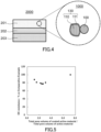
- FIG. 5 is a graph showing a relation between the DC resistance and the total pore volume ratio.
- the horizontal axis indicates the total pore volume ratio in Table 1.
- the vertical axis indicates the DC resistance in Table 1.
- FIG. 6 is a graph showing a relation between the resistance increase rate and the total pore volume ratio.
- the horizontal axis indicates the total pore volume ratio in Table 1.
- the vertical axis indicates the resistance increase rate in Table 1.
- the total pore volume ratio is a ratio of the total pore volume of the coated active material to the total pore volume of the NCA.
- the DC resistance of the battery decreased with decreasing total pore volume ratio. It is inferred that the adhesiveness between the coated active material and the sulfide solid electrolyte was improved and the resistance of the battery was reduced because the LTAF particles were more reliably adhered to the NCA particles and a fine structure was formed more appropriately with increasing processing time.
- Example 2 Example 3, and Example 6 whose total pore volume ratios were smaller than the total pore volume ratio of Example 5 showed a DC resistance higher than that of Example 5. That is, a tendency for the DC resistance to be reduced with decreasing total pore volume ratio was observed. It is inferred that when the total pore volume ratio sufficiently decreased, the surface of the particle of the coated active material was sufficiently smooth and therefore a joining condition between the coated active material and other materials, such as the sulfide solid electrolyte and the binder, deteriorated. Note that the battery of Example 3 whose total pore volume ratio was 1.2 also showed sufficiently low DC resistance and resistance increase rate.
- the technique of the present disclosure is useful, for example, for all-solid-state lithium secondary batteries.
Landscapes
- Chemical & Material Sciences (AREA)
- Chemical Kinetics & Catalysis (AREA)
- Electrochemistry (AREA)
- General Chemical & Material Sciences (AREA)
- Composite Materials (AREA)
- Inorganic Chemistry (AREA)
- Engineering & Computer Science (AREA)
- Manufacturing & Machinery (AREA)
- Condensed Matter Physics & Semiconductors (AREA)
- General Physics & Mathematics (AREA)
- Physics & Mathematics (AREA)
- Battery Electrode And Active Subsutance (AREA)
- Secondary Cells (AREA)
Applications Claiming Priority (2)
| Application Number | Priority Date | Filing Date | Title |
|---|---|---|---|
| JP2022094646 | 2022-06-10 | ||
| PCT/JP2023/017474 WO2023238582A1 (ja) | 2022-06-10 | 2023-05-09 | 被覆活物質、電極材料および電池 |
Publications (2)
| Publication Number | Publication Date |
|---|---|
| EP4539162A1 true EP4539162A1 (de) | 2025-04-16 |
| EP4539162A4 EP4539162A4 (de) | 2025-12-31 |
Family
ID=89118189
Family Applications (1)
| Application Number | Title | Priority Date | Filing Date |
|---|---|---|---|
| EP23819566.3A Pending EP4539162A4 (de) | 2022-06-10 | 2023-05-09 | Beschichtetes aktivmaterial, elektrodenmaterial und batterie |
Country Status (5)
| Country | Link |
|---|---|
| US (1) | US20250105279A1 (de) |
| EP (1) | EP4539162A4 (de) |
| JP (1) | JPWO2023238582A1 (de) |
| CN (1) | CN119301774A (de) |
| WO (1) | WO2023238582A1 (de) |
Cited By (1)
| Publication number | Priority date | Publication date | Assignee | Title |
|---|---|---|---|---|
| EP4404216A4 (de) * | 2021-09-15 | 2025-10-15 | Panasonic Ip Man Co Ltd | Festelektrolytmaterial und batterie damit |
Family Cites Families (4)
| Publication number | Priority date | Publication date | Assignee | Title |
|---|---|---|---|---|
| JP2021150226A (ja) * | 2020-03-23 | 2021-09-27 | トヨタ自動車株式会社 | 被膜付き正極活物質粒子の製造方法 |
| WO2021205821A1 (ja) * | 2020-04-09 | 2021-10-14 | パナソニックIpマネジメント株式会社 | 正極材料および電池 |
| WO2022004397A1 (ja) * | 2020-06-29 | 2022-01-06 | パナソニックIpマネジメント株式会社 | 正極材料および電池 |
| JPWO2023037816A1 (de) * | 2021-09-13 | 2023-03-16 |
-
2023
- 2023-05-09 JP JP2024526313A patent/JPWO2023238582A1/ja active Pending
- 2023-05-09 WO PCT/JP2023/017474 patent/WO2023238582A1/ja not_active Ceased
- 2023-05-09 CN CN202380044361.3A patent/CN119301774A/zh active Pending
- 2023-05-09 EP EP23819566.3A patent/EP4539162A4/de active Pending
-
2024
- 2024-12-06 US US18/972,177 patent/US20250105279A1/en active Pending
Cited By (1)
| Publication number | Priority date | Publication date | Assignee | Title |
|---|---|---|---|---|
| EP4404216A4 (de) * | 2021-09-15 | 2025-10-15 | Panasonic Ip Man Co Ltd | Festelektrolytmaterial und batterie damit |
Also Published As
| Publication number | Publication date |
|---|---|
| EP4539162A4 (de) | 2025-12-31 |
| WO2023238582A1 (ja) | 2023-12-14 |
| JPWO2023238582A1 (de) | 2023-12-14 |
| CN119301774A (zh) | 2025-01-10 |
| US20250105279A1 (en) | 2025-03-27 |
Similar Documents
| Publication | Publication Date | Title |
|---|---|---|
| US20240405202A1 (en) | Coated active material, electrode material, and battery | |
| US20240055598A1 (en) | Composite positive electrode active material, positive electrode material, and battery | |
| US20240079570A1 (en) | Coated active material, positive electrode material, positive electrode, and battery | |
| EP4404290A1 (de) | Positivelektrodenmaterial, positivelektrode und batterie | |
| US20240204247A1 (en) | Positive electrode material, positive electrode, and battery | |
| US20240079569A1 (en) | Coated active material, positive electrode material, positive electrode, and battery | |
| US20250105279A1 (en) | Coated active material, electrode material, and battery | |
| US20240266514A1 (en) | Coated active material, electrode material and battery | |
| US20240266595A1 (en) | Coated active material, electrode material and battery | |
| US20240372081A1 (en) | Battery | |
| US20240079646A1 (en) | Coated active material, positive electrode material, positive electrode, and battery | |
| US20240154102A1 (en) | Negative electrode active material and battery | |
| EP4539161A1 (de) | Beschichtetes aktivmaterial, elektrodenmaterial und batterie | |
| EP4539154A1 (de) | Beschichtetes aktivmaterial, elektrodenmaterial und batterie | |
| EP4539163A1 (de) | Beschichtetes aktivmaterial, elektrodenmaterial, batterie und batterieherstellungsverfahren | |
| CN117378055A (zh) | 被覆活性物质、电极材料和电池 | |
| US20240088435A1 (en) | Positive electrode material, positive electrode, and battery | |
| EP4557430A1 (de) | Verfahren zur herstellung eines festelektrolyten und festelektrolyt |
Legal Events
| Date | Code | Title | Description |
|---|---|---|---|
| STAA | Information on the status of an ep patent application or granted ep patent |
Free format text: STATUS: THE INTERNATIONAL PUBLICATION HAS BEEN MADE |
|
| PUAI | Public reference made under article 153(3) epc to a published international application that has entered the european phase |
Free format text: ORIGINAL CODE: 0009012 |
|
| STAA | Information on the status of an ep patent application or granted ep patent |
Free format text: STATUS: REQUEST FOR EXAMINATION WAS MADE |
|
| 17P | Request for examination filed |
Effective date: 20241219 |
|
| AK | Designated contracting states |
Kind code of ref document: A1 Designated state(s): AL AT BE BG CH CY CZ DE DK EE ES FI FR GB GR HR HU IE IS IT LI LT LU LV MC ME MK MT NL NO PL PT RO RS SE SI SK SM TR |
|
| DAV | Request for validation of the european patent (deleted) | ||
| DAX | Request for extension of the european patent (deleted) | ||
| REG | Reference to a national code |
Ref country code: DE Ref legal event code: R079 Free format text: PREVIOUS MAIN CLASS: H01M0004525000 Ipc: H01M0004360000 |
|
| A4 | Supplementary search report drawn up and despatched |
Effective date: 20251201 |
|
| RIC1 | Information provided on ipc code assigned before grant |
Ipc: H01M 4/36 20060101AFI20251125BHEP Ipc: H01M 4/525 20100101ALI20251125BHEP Ipc: H01M 4/62 20060101ALI20251125BHEP Ipc: H01M 10/0562 20100101ALI20251125BHEP Ipc: H01M 4/02 20060101ALN20251125BHEP |