EP4539038A1 - Electric propulsion apparatus for a motor vehicle with generation of sounds depending on the operation thereof - Google Patents
Electric propulsion apparatus for a motor vehicle with generation of sounds depending on the operation thereof Download PDFInfo
- Publication number
- EP4539038A1 EP4539038A1 EP24205238.9A EP24205238A EP4539038A1 EP 4539038 A1 EP4539038 A1 EP 4539038A1 EP 24205238 A EP24205238 A EP 24205238A EP 4539038 A1 EP4539038 A1 EP 4539038A1
- Authority
- EP
- European Patent Office
- Prior art keywords
- magnet
- magnetic field
- rotor
- axis
- motor
- Prior art date
- Legal status (The legal status is an assumption and is not a legal conclusion. Google has not performed a legal analysis and makes no representation as to the accuracy of the status listed.)
- Pending
Links
Images




Classifications
-
- G—PHYSICS
- G10—MUSICAL INSTRUMENTS; ACOUSTICS
- G10K—SOUND-PRODUCING DEVICES; METHODS OR DEVICES FOR PROTECTING AGAINST, OR FOR DAMPING, NOISE OR OTHER ACOUSTIC WAVES IN GENERAL; ACOUSTICS NOT OTHERWISE PROVIDED FOR
- G10K15/00—Acoustics not otherwise provided for
- G10K15/02—Synthesis of acoustic waves
-
- H—ELECTRICITY
- H02—GENERATION; CONVERSION OR DISTRIBUTION OF ELECTRIC POWER
- H02K—DYNAMO-ELECTRIC MACHINES
- H02K7/00—Arrangements for handling mechanical energy structurally associated with dynamo-electric machines, e.g. structural association with mechanical driving motors or auxiliary dynamo-electric machines
- H02K7/06—Means for converting reciprocating motion into rotary motion or vice versa
- H02K7/065—Electromechanical oscillators; Vibrating magnetic drives
-
- H—ELECTRICITY
- H02—GENERATION; CONVERSION OR DISTRIBUTION OF ELECTRIC POWER
- H02K—DYNAMO-ELECTRIC MACHINES
- H02K1/00—Details of the magnetic circuit
- H02K1/06—Details of the magnetic circuit characterised by the shape, form or construction
- H02K1/22—Rotating parts of the magnetic circuit
- H02K1/27—Rotor cores with permanent magnets
- H02K1/2706—Inner rotors
Definitions
- the reference number 1 is used to indicate, as a whole, a motor vehicle.
- the motor vehicle 1 has a body 2, multiple wheels 3, and a suspension assembly not illustrated and configured to suspend the body 2 with respect to the wheels 3.
- the electric motor 5 is, thus, part of a propulsion apparatus of the motor vehicle 1.
- the motor 5 has a rotor 7 and a stator 8 coaxial to each other around a rotor axis R.
- Either the stator 8 or the rotor 7 is supplied with electric current, so that a magnetic interaction is created with magnetic elements of the other, either the stator 8 or the rotor 7.
- the rotor 7 preferably comprises a magnet 10, specifically a permanent one, with a magnetic axis radial to the axis R.
- the magnet 10 has two opposite magnetic poles along a direction radial to the axis R.
- harmonic oscillators 11, 12, 13 comprise respective magnets 15, 16, 17, in particular permanent ones, and respective elastic elements 18 that suspend, respectively, the magnets 15, 16, 17 from the supports 14.
- the rotating field emitted by the motor 5 could be or comprise the magnetic field produced by the magnet or magnets 10, the magnetic field produced by the interaction between the rotor 7 and the stator 8, or even a combination of these two magnetic fields.
- the magnets 15, 16, 17 oscillate with respect to the supports 14 as a function of the rotating magnetic field to which they are exposed or subject.
- the harmonic oscillators 11, 12, 13 may be mathematically modelled as having at least respective stiffnesses and masses, of which the natural frequencies are a function.
- the natural frequency is defined as the square root of the ratio of stiffness to mass.
- diametrically opposite positions does not necessarily mean positions aligned along a straight axis, but positions that have at least one angular distance greater than a right angle or, in particular, greater than or equal to 120°, more preferably greater than or equal to 135°.
- the magnets 16, 17 or, more generally, the harmonic oscillators 12, 13 are positioned so they are aligned along a straight direction, in particular perpendicular and radial to the axis R; here, the magnet 15 with the corresponding harmonic oscillator 11 are not included.
- the frequency of the externally applied magnetic force on the harmonic oscillators 11, 12, 13, 20 due precisely to the alternation between attraction and repulsion will correspond to the rotation frequency of the motor 5 or, more precisely, of the rotor 7.
- the elastic elements 18 could comprise any elastic body suitable for enabling the oscillation of the magnets 15, 16, 17.
- the elastic elements 18 are generically represented as springs.
- the tubes 23 extend from the ends 23a until terminating with respective ends 23b, which, in particular, coincide with each other.
- the tubes 23 connect with each other to form a single common tube section 23c defined from the connection point until the end 23b.
- Such a sound reproduction system could have sound pressure sensors configured to detect the sound pressure waves caused by the harmonic oscillators 11, 12, 13 and to generate corresponding sound signals (for example electric ones), an optional conditioning device configured to condition the sound signals, and a loudspeaker device configured to reproduce a sound corresponding to the sound signals, optionally conditioned.
- sound pressure sensors configured to detect the sound pressure waves caused by the harmonic oscillators 11, 12, 13 and to generate corresponding sound signals (for example electric ones)
- an optional conditioning device configured to condition the sound signals
- a loudspeaker device configured to reproduce a sound corresponding to the sound signals, optionally conditioned.
- the sound reproduction system could be combined with sound boxes, in the sense that the sound pressure sensors detect the sound pressure waves amplified or conditioned by the sound boxes.
- the sound boxes may also, for example, be integrated with the tubes 23.
- the harmonic oscillators 11, 12, 13 generate pleasant sounds for low operating conditions of the motor 5, corresponding to a low angular speed of the rotor 7.
- the sounds have a low frequency and high intensity, comparable to the sounds produced by a vehicle provided with an internal combustion engine.
Landscapes
- Engineering & Computer Science (AREA)
- Power Engineering (AREA)
- Health & Medical Sciences (AREA)
- Audiology, Speech & Language Pathology (AREA)
- General Health & Medical Sciences (AREA)
- Physics & Mathematics (AREA)
- Acoustics & Sound (AREA)
- Multimedia (AREA)
- Connection Of Motors, Electrical Generators, Mechanical Devices, And The Like (AREA)
- Permanent Magnet Type Synchronous Machine (AREA)
Abstract
Description
- This patent application claims priority from
Italian patent application no. 102023000021336 filed on October 13, 2023 - The invention relates to an electric propulsion apparatus for a motor vehicle and, more specifically, the aspect of the sound emission of the apparatus.
- Some motor vehicles only use electric motors as propulsion means and, therefore, are commonly called fully electric or, simply, electric vehicles.
- During their operation, the electric motors emit sounds normally considered faint or even unpleasant.
- In fact, in the field of motor vehicles, the electric motors used are normally those suitable for rotating at relatively high speeds, so as to limit the bulk and weight; as a result, the sounds produced have intensities that become relatively significant in the field of high frequencies.
- Thus, the sounds produced overall are perceived by the human ear as unpleasant whistles.
- This has a negative impact on the driver since the latter is less engaged in driving, less aware of the operating state of the motor, or even disturbed by the unpleasantness of the sounds.
- Therefore, there is a need to improve the quality of the sounds perceived by the driver of an electric vehicle, in particular with the aim of increasing the involvement and awareness of the driver with respect to the operating condition of the motor vehicle.
- One purpose of the invention is to respond to the need identified above, preferably in a simple and reliable way.
- The purpose is achieved with a propulsion apparatus according to claim 1.
- The dependent claims define particular embodiments of the invention.
- Below, embodiments of the invention are described to better understand the same by way of non-limiting examples and with reference to the attached drawings in which:
-
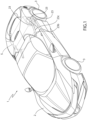
Figure 1 is a perspective view of a motor vehicle comprising a propulsion apparatus according to the invention, -
Figure 2 is a perspective view, on an enlarged scale and with parts removed for clarity, of a portion of the propulsion apparatus, -
Figure 3 is a cross section of the propulsion apparatus according to a plane section defined by the line III-III inFigure 2 , -
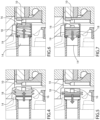
Figures 4, 5 are parts detailing the cross section inFigure 3 and correspond to two respective, distinct operating conditions of the propulsion apparatus, -
Figures 6, 7 are similar toFigures 4, 5 , but with some elastic components represented in a schematic form, -
Figure 8 is a diagram of the positioning of some magnets of the propulsion apparatus, -
Figure 9 is a diagram of a variant of the positioning ofFigure 8 , and -
Figures 10-12 are diagrams of additional variants of the positioning inFigures 8, 9 . - In
Figure 1 , the reference number 1 is used to indicate, as a whole, a motor vehicle. - Normally, the motor vehicle 1 has a
body 2,multiple wheels 3, and a suspension assembly not illustrated and configured to suspend thebody 2 with respect to thewheels 3. - The
wheels 3 represent known traction means for moving the motor vehicle 1, but for the purposes of the invention they could be replaced by any other suitable means, even unusual ones, like, for example, tracked means. - The motor vehicle 1 also comprises an
electric motor 5 for propelling the motor vehicle 1, as well as, in particular, atransmission assembly 6. - The
electric motor 5 is, thus, part of a propulsion apparatus of the motor vehicle 1. - The
electric motor 5 is configured to deliver mechanical power; thetransmission assembly 6 is configured to transmit the mechanical power delivered to two of thewheels 3 to move the motor vehicle 1. - The
transmission assembly 6 could also be configured to transmit the mechanical power to all thewheels 3 or, more generally, to the traction means of the motor vehicle 1. - Optionally, the
transmission assembly 6 could also have the function of reducing the output speed of themotor 5, thus rotating thewheels 3 at a reduced rotation speed with respect to the output speed of themotor 5. - During the operation of the
motor 5, i.e. while themotor 5 delivers mechanical power, thesame motor 5 emits a rotating magnetic field. - More specifically, the
motor 5 has a rotor 7 and astator 8 coaxial to each other around a rotor axis R. - Either the
stator 8 or the rotor 7 is supplied with electric current, so that a magnetic interaction is created with magnetic elements of the other, either thestator 8 or the rotor 7. - The magnetic interaction corresponds to the rotating magnetic field, which is the cause of a rotation of the rotor 7 with respect to the
stator 8 around the rotor axis R. - The magnetic principles linked to the operation of the electric motors are generally known, so they are not explained in further detail here. In particular, the generation of a rotating magnetic field by an electric motor is an underlying principle of the operation of the electric motor.
- The magnetic field generated by the
motor 5 rotates around the rotor axis R, i.e., it follows the rotation direction of the rotor 7. - More specifically, the magnetic field develops between two opposite magnetic poles, which are, ideally, connected by a magnetic axis.
- Here, the magnetic axis is perpendicular to the rotor axis R and rotates around the latter on a plane perpendicular to the rotor axis R.
- From hereon, "magnetic axis" means an axis extending between the two magnetic poles of a magnet or magnetic field.
- The rotor 7 extends axially along the axis R between two
axial ends intermediate portion 7c between theends - At least the
intermediate portion 7c interacts magnetically with thestator 8 according to a direction that is radial to the axis R. Therefore, theintermediate portion 7c defines a radial magnetic interaction portion of the rotor 7. - The
portion 7b is clearly fixed to theintermediate portion 7c. - The rotor 7 preferably comprises a
magnet 10, specifically a permanent one, with a magnetic axis radial to the axis R. In other words, themagnet 10 has two opposite magnetic poles along a direction radial to the axis R. - In particular, the
magnet 10 is part of theend 7b or is supported by theend 7b in a fixed way with respect to the latter. More specifically, theportion 7b may be defined by themagnet 10. - In the embodiment illustrated, the
magnet 10 is part of a disc fixed to theend 7b and with which the rotor 7 axially terminates along the axis R on the side of theend 7b. Themagnet 10 may also, optionally, be defined by the disc mentioned above or, more generally, by a body fixed to theend 7b and whereby the rotor 7 axially terminates along the axis R on the side of theend 7b. - As far as regards the magnetic axis of the
magnet 10, the latter 10 may instead have, alternatively, a magnetic axis parallel to the axis R and be arranged eccentrically, i.e. radially spaced apart by the axis R, so as to have two magnetic poles of which one is exposed to theend 7a, i.e. axially towards the inside of themotor 5, and the other is exposed in the opposite direction, i.e. axially towards the outside of themotor 5. - In addition, in the latter case, the rotor 7 could preferably comprise another
magnet 10 with a magnetic axis parallel to the axis R and arranged, for example, in a position diametrically opposite the precedingmagnet 10 and, more precisely, along the same radial direction, i.e. preferably in a position aligned along a straight, radial direction. Here, theadditional magnet 10 would have magnetic poles inverted with respect to the precedingmagnet 10. - Clearly, the rotor 7 could even comprise
multiple magnets 10 with respective magnetic axes parallel to the axis R and arranged, for example, circumferentially distributed, in particular with twomagnet 10 halves arranged along respective adjacent circumference halves around the axis R and the poles of one ofmagnet 10 halves inverted with respect to those of the other half. - In any case, the magnetic field produced by the
magnet 10 or by themagnets 10 would, in any case, be a rotating magnetic field, since thesemagnets 10 would be fixed or incorporated into the rotor 7, and, in any case, a magnetic field emitted by themotor 5 during its operation, since belonging to themotor 5. - For this reason, the
magnet 10 may not even be included, so that the rotating magnetic field emitted by themotor 5 would consist of the magnetic field resulting from the magnetic interaction between the rotor 7 and thestator 8. - According to the invention, the propulsion apparatus of the motor vehicle 1 comprises, in addition to the
electric motor 5, at least oneharmonic oscillator 11. - In this case, the propulsion apparatus also comprises another two
harmonic oscillators - Each of the
harmonic oscillators corresponding support 14, which could be, for example, fixed to an external casing of themotor 5. - In addition, the
harmonic oscillators respective magnets elastic elements 18 that suspend, respectively, themagnets supports 14. - Each of the
magnets motor 5 so as to have a corresponding magnetic pole exposed to the rotating field emitted by themotor 5. - As previously mentioned, the rotating field emitted by the
motor 5 could be or comprise the magnetic field produced by the magnet ormagnets 10, the magnetic field produced by the interaction between the rotor 7 and thestator 8, or even a combination of these two magnetic fields. - In more detail, the
magnets magnets - Thus, the
magnets magnets magnet 10 ormagnets 10 according to the axis R; alternatively or in addition, themagnets - Conveniently, the
harmonic oscillators respective guiding devices 19 configured to respectively guide themagnets - By means of the
elastic elements 18, themagnets supports 14 as a function of the rotating magnetic field to which they are exposed or subject. - In this way, the oscillation of the
magnets elastic elements 18 or even the movement of the surrounding air caused by the movement of themagnets - At least one of the
harmonic oscillators harmonic oscillators harmonic oscillators - In this way, the frequencies of the sound pressure waves produced by the oscillation of the
magnets - In practice, the
harmonic oscillators - Therefore, the masses and/or stiffness of the
harmonic oscillators - Each of the
magnets magnet 17 with respect to a rotation axis of the rotating magnetic field, here, specifically, coinciding with the rotor axis R. - More preferably, the
magnets - In fact, more generally, "diametrically opposite positions" does not necessarily mean positions aligned along a straight axis, but positions that have at least one angular distance greater than a right angle or, in particular, greater than or equal to 120°, more preferably greater than or equal to 135°.
- In the variant in
Figure 9 , the propulsion apparatus comprises an additionalharmonic oscillator 20 with itssupport 14, itselastic element 18, and amagnet 21, which is arranged in a diametrically opposite position to themagnet 16. More precisely, but not necessarily, themagnets - In the variant in
Figure 10 , themagnets harmonic oscillators magnet 15 with the correspondingharmonic oscillator 11 are not included. - The alignment of the
magnets motor 5. - The variant in
Figure 11 is similar to the variant inFigure 10 with the addition of themagnet 15 and correspondingharmonic oscillator 11 at an angular distance closer to themagnet 16, in particular less than 60°. The production of the sound by theharmonic oscillator 11 will have a slight phase delay here with respect to the sound produced by the other twoharmonic oscillators - The variant in
Figure 12 is similar to the variant inFigure 11 with the addition of themagnet 21 and of the correspondingharmonic oscillator 20 positioned so that it is aligned along a straight direction, in particular perpendicular and radial to the axis R, with respect to themagnet 15 and to the correspondingharmonic oscillator 11. - The
magnets magnet 17 or themagnet 21 inFigures 9 and12 . - In this way, all the
magnets magnet 10 or the rotating magnetic field of themotor 5. - For example, supposing that the
magnets magnets magnets magnets magnets motor 5. - The speed of the alternation between attraction and repulsion will be determined by the speed of the
motor 5 or, more precisely, by the angular speed of the rotor 7. - Therefore, the frequency of the externally applied magnetic force on the
harmonic oscillators motor 5 or, more precisely, of the rotor 7. - Thus, the frequency of the sound pressure waves will also be correlated, in particular positively, to the frequency of the externally applied magnetic force and, thus, to the operating state of the
motor 5. - Each of the
elastic elements 18 preferably, independently comprises an axially deformable elastic tubular body (here deformable along a direction parallel to the axis R), preferably of the bellows type (Figures 4 and 5 ) . - This is not, however, necessary, since the
elastic elements 18 could comprise any elastic body suitable for enabling the oscillation of themagnets Figures 6, 7 , theelastic elements 18 are generically represented as springs. -
Figures 4 and 6 show the attraction betweenmagnet 16 andmagnet 10, whileFigures 5, 7 show the repulsion betweenmagnet 16 andmagnet 10. - The elastic tubular body is fixed to the
corresponding support 14, which has, in particular, a through hole communicating with the inside of the tubular body. - The tubular body has two opposite, axial ends, of which one communicates with the through hole of the
support 14 and the other is fixed to its magnet between themagnets - The propulsion apparatus preferably also comprises a
sound transmission device 22 configured to transmit the sound pressure waves generated by theharmonic oscillators body 2 and comprises at least one seat for the driver of the motor vehicle 1. - In particular, the
sound transmission device 22 comprises a plurality oftubes 23 havingends 23a arranged, respectively, at theharmonic oscillators tubes 23 may receive, as input, the sound pressure waves produced by theharmonic oscillators - Furthermore, the
tubes 23 extend from theends 23a until terminating withrespective ends 23b, which, in particular, coincide with each other. In fact, thetubes 23 connect with each other to form a singlecommon tube section 23c defined from the connection point until theend 23b. - The
end 23b communicates with the passenger compartment, so that, in particular, it leads into the passenger compartment. - Thus, the sound pressure waves are transported to the passenger compartment through the
tubes 23. - Alternatively, or in addition, the
transmission device 22 could comprise one or more sound boxes along the path of the sound pressure waves towards the passenger compartment. The sound boxes may have the function of conditioning the sound pressure waves, for example, amplifying them and/or conditioning the timbre of the sound associated with these waves. - The
transmission device 22 could even, alternatively or in addition, comprise a sound reproduction system. - Such a sound reproduction system could have sound pressure sensors configured to detect the sound pressure waves caused by the
harmonic oscillators - The sound reproduction system could be combined with sound boxes, in the sense that the sound pressure sensors detect the sound pressure waves amplified or conditioned by the sound boxes.
- The sound boxes may also, for example, be integrated with the
tubes 23. - The tubular bodies of the
elastic elements 18 communicate with theends 23a, so that the pressure waves that are directly generated inside the tubular bodies pass to thetubes 23. - More specifically, the communication between tubular bodies and
tubes 23 occurs via the through holes of thesupports 14, to which thetubes 23 are coupled. The ends 23a are fixed to thesupports 14, in particular on the side axially opposite the tubular bodies. Thus, in detail, thesupports 14 are arranged between the tubular bodies and thetubes 23. - From the above, the advantages of the propulsion apparatus according to the invention are clear.
- The
harmonic oscillators motor 5, corresponding to a low angular speed of the rotor 7. In fact, the sounds have a low frequency and high intensity, comparable to the sounds produced by a vehicle provided with an internal combustion engine. - The frequency of the sounds, in addition, will increase with the increase in revolutions of the motor, since the frequency of the externally applied magnetic force that causes the oscillation of the
magnets - This aspect also clearly recalls what happens with the sounds produced by a conventional internal combustion engine.
- The solution adopted is simple, since it does not require complex components, but uses the same magnet operating principles of the
electric motor 5. - In fact, the solution adopted may basically be applied to any type of electric motor and any type of hybrid or electric vehicle.
- The possibility of varying the natural frequencies of the
harmonic oscillators - Finally, it is clear that changes may be made to the propulsion apparatus according to the invention, and variations produced thereto, that, in any case, do not depart from the scope of protection defined by the claims.
- In particular, the number and shape of the components described and illustrated could be different.
- In addition, the variants and embodiments described and illustrated may be combined with each other, without thus departing from the protective scope defined by the claims.
Claims (10)
- - Propulsion apparatus for a motor vehicle (1), the apparatus comprising- an electric motor (5) configured to emit a rotating magnetic field during operation, and- at least one harmonic oscillator (11, 12, 13) arranged to interact with the rotating magnetic field emitted by the motor (5),wherein the harmonic oscillator (11, 12, 13) comprises at least one support (14), a first magnet (15, 16, 17, 21) arranged to have a first magnetic pole exposed to the rotating magnetic field emitted by the electric motor (5), and an elastic element (18) suspending the first magnet (15, 16, 17, 21) to the support (14), such that the first magnet (15, 16, 17, 21) oscillates with respect to the support (14) as a function of the rotating magnetic field, thereby inducing a sound pressure wave corresponding to the oscillation of the first magnet (15, 16, 17, 21) and the elastic element (18).
- - The apparatus according to claim 1, wherein the electric motor (5) comprises a rotor (7) and a stator (8) coaxial about a rotor axis (R), the rotor (7) being rotatable with respect to the stator (8) about the rotor axis (R) and comprising a second magnet (10) with a magnetic axis radial with respect to the rotor axis (R), the second magnet (10) being axially facing the first pole according to the rotor axis (R).
- - The apparatus according to claim 2, wherein the rotor (7) comprises a radial magnetic interaction portion (7c) configured to magnetically interact with the stator (8) according to a radial direction with respect to the rotor axis (R) and an axial end portion (7b), according to the rotor axis (R), comprising the or defined by the second magnet (10) and fixed with respect to the radial magnetic interaction portion (7c).
- - The apparatus according to any one of the preceding claims, further comprising an additional harmonic oscillator (11, 12, 13, 20) with a third magnet (15, 16, 17, 21) arranged to have a second magnetic pole exposed to the rotating magnetic field emitted by the electric motor (5).
- - The apparatus according to claim 4, in which the harmonic oscillators (11, 12, 13, 20) have natural frequencies different from each other.
- - The apparatus according to claim 4 or 5, wherein the third magnet (15, 16, 17, 21) is arranged to have a position diametrically opposite to the first magnet (15, 16, 17, 21) with respect to an axis of rotation (R) of the rotating magnetic field, and wherein the second magnetic pole has a magnetic polarity opposite to the first magnetic pole.
- - The apparatus according to any of the preceding claims, comprising sound transmission means (22) configured to transmit the sound pressure wave to a passenger compartment of the motor vehicle (1).
- - The apparatus according to claim 7, wherein the sound transmitting means (22) comprise a tube (23) having a first end (23a) disposed at the harmonic oscillator (11, 12, 13), the tube (23) being configured to extend up to terminate with a further end (23b) to be put in communication with the passenger compartment.
- - The apparatus according to claim 8, wherein the elastic element (18) comprises an axially deformable elastic tubular body, preferably of the bellows type, the tubular body (18) being communicating with and carried by the first end (23a) of the tube (23).
- - Motor vehicle (1) comprising a propulsion apparatus according to any of the preceding claims.
Applications Claiming Priority (1)
| Application Number | Priority Date | Filing Date | Title |
|---|---|---|---|
| IT102023000021336A IT202300021336A1 (en) | 2023-10-13 | 2023-10-13 | ELECTRIC PROPULSION SYSTEM FOR A MOTOR VEHICLE WITH SOUND GENERATION DEPENDENT ON ITS OPERATION |
Publications (1)
| Publication Number | Publication Date |
|---|---|
| EP4539038A1 true EP4539038A1 (en) | 2025-04-16 |
Family
ID=89308128
Family Applications (1)
| Application Number | Title | Priority Date | Filing Date |
|---|---|---|---|
| EP24205238.9A Pending EP4539038A1 (en) | 2023-10-13 | 2024-10-08 | Electric propulsion apparatus for a motor vehicle with generation of sounds depending on the operation thereof |
Country Status (4)
| Country | Link |
|---|---|
| US (1) | US20250125680A1 (en) |
| EP (1) | EP4539038A1 (en) |
| CN (1) | CN119821101A (en) |
| IT (1) | IT202300021336A1 (en) |
Citations (4)
| Publication number | Priority date | Publication date | Assignee | Title |
|---|---|---|---|---|
| US20110304445A1 (en) * | 2010-06-09 | 2011-12-15 | Denso Corporation | Vehicle Presence Notification Apparatus |
| US20160101726A1 (en) * | 2014-10-11 | 2016-04-14 | Hyundai Motor Company | Vehicle, apparatus for generating driving sound of vehicle, and apparatus and method for controlling driving sound of vehicle |
| US20210101480A1 (en) * | 2019-10-03 | 2021-04-08 | Toyota Motor Engineering & Manufacturing North America, Inc. | Electric or hybrid electric vehicle having adjustable vertical electric drive motor and method of making and using |
| US20230144723A1 (en) * | 2021-11-09 | 2023-05-11 | Fca Us Llc | Battery electric vehicle active sound and vibration enhancement systems |
-
2023
- 2023-10-13 IT IT102023000021336A patent/IT202300021336A1/en unknown
-
2024
- 2024-09-30 US US18/902,552 patent/US20250125680A1/en active Pending
- 2024-10-08 EP EP24205238.9A patent/EP4539038A1/en active Pending
- 2024-10-11 CN CN202411415308.2A patent/CN119821101A/en active Pending
Patent Citations (4)
| Publication number | Priority date | Publication date | Assignee | Title |
|---|---|---|---|---|
| US20110304445A1 (en) * | 2010-06-09 | 2011-12-15 | Denso Corporation | Vehicle Presence Notification Apparatus |
| US20160101726A1 (en) * | 2014-10-11 | 2016-04-14 | Hyundai Motor Company | Vehicle, apparatus for generating driving sound of vehicle, and apparatus and method for controlling driving sound of vehicle |
| US20210101480A1 (en) * | 2019-10-03 | 2021-04-08 | Toyota Motor Engineering & Manufacturing North America, Inc. | Electric or hybrid electric vehicle having adjustable vertical electric drive motor and method of making and using |
| US20230144723A1 (en) * | 2021-11-09 | 2023-05-11 | Fca Us Llc | Battery electric vehicle active sound and vibration enhancement systems |
Also Published As
| Publication number | Publication date |
|---|---|
| CN119821101A (en) | 2025-04-15 |
| US20250125680A1 (en) | 2025-04-17 |
| IT202300021336A1 (en) | 2025-04-13 |
Similar Documents
| Publication | Publication Date | Title |
|---|---|---|
| EP2503792B1 (en) | Moving armature receiver assemblies with vibration suppression | |
| JP4426969B2 (en) | Small electric appliance with drive mechanism for generating oscillating motion | |
| KR102428403B1 (en) | Sound generator system of vehicle | |
| CN110012398B (en) | Balanced vibration system | |
| JPH0766888B2 (en) | Permanent magnet device with attached coil device | |
| JP2015071410A (en) | Rotary-wing aircraft rotary wing with vibration damper | |
| CN104632320A (en) | Actuator arrangement on a vehicle structure | |
| CN101557982A (en) | Disk-shaped floating aircraft | |
| JP5834595B2 (en) | Vibration isolator for vehicle | |
| EP4539038A1 (en) | Electric propulsion apparatus for a motor vehicle with generation of sounds depending on the operation thereof | |
| JP2021078180A (en) | Power transmission device | |
| JP2012122612A (en) | Active vibratory control device, vehicle including such device, and active mounting base for such device | |
| CN110774880A (en) | vehicle drive | |
| JPH07303346A (en) | Electric motor and device provided with the motor | |
| JP2016015812A (en) | Electric motor | |
| CN111083608A (en) | Vibration-damping moving-coil loudspeaker | |
| ES2369197T3 (en) | PIECE OF FORM FOR THE SETTING OF AN EXCITER FOR A FLAT MEMBRANE SPEAKER. | |
| JPH11234956A (en) | Vibration damping structure of sr motor | |
| KR101578673B1 (en) | High Power Acoustic Vibration Exciter Module | |
| JP2014121902A (en) | Steering wheel | |
| WO2019235548A1 (en) | Vibration reduction method, motor, neutralizer, and electric power steering device | |
| CN218858159U (en) | Accelerator pedal mechanism | |
| US1845575A (en) | Motor and motor horn | |
| JP2018113781A (en) | Power generator | |
| JPH11226500A (en) | Vibration generator |
Legal Events
| Date | Code | Title | Description |
|---|---|---|---|
| PUAI | Public reference made under article 153(3) epc to a published international application that has entered the european phase |
Free format text: ORIGINAL CODE: 0009012 |
|
| STAA | Information on the status of an ep patent application or granted ep patent |
Free format text: STATUS: THE APPLICATION HAS BEEN PUBLISHED |
|
| AK | Designated contracting states |
Kind code of ref document: A1 Designated state(s): AL AT BE BG CH CY CZ DE DK EE ES FI FR GB GR HR HU IE IS IT LI LT LU LV MC ME MK MT NL NO PL PT RO RS SE SI SK SM TR |
|
| STAA | Information on the status of an ep patent application or granted ep patent |
Free format text: STATUS: REQUEST FOR EXAMINATION WAS MADE |
|
| 17P | Request for examination filed |
Effective date: 20251006 |
|
| GRAP | Despatch of communication of intention to grant a patent |
Free format text: ORIGINAL CODE: EPIDOSNIGR1 |
|
| STAA | Information on the status of an ep patent application or granted ep patent |
Free format text: STATUS: GRANT OF PATENT IS INTENDED |
|
| RIC1 | Information provided on ipc code assigned before grant |
Ipc: G10K 15/02 20060101AFI20251104BHEP |
|
| INTG | Intention to grant announced |
Effective date: 20251201 |
|
| GRAS | Grant fee paid |
Free format text: ORIGINAL CODE: EPIDOSNIGR3 |
|
| GRAA | (expected) grant |
Free format text: ORIGINAL CODE: 0009210 |
|
| STAA | Information on the status of an ep patent application or granted ep patent |
Free format text: STATUS: THE PATENT HAS BEEN GRANTED |