EP4538667A2 - Verfahren und vorrichtung zur analyse von aufzeichnungen bei der leckdetektion - Google Patents
Verfahren und vorrichtung zur analyse von aufzeichnungen bei der leckdetektion Download PDFInfo
- Publication number
- EP4538667A2 EP4538667A2 EP24222885.6A EP24222885A EP4538667A2 EP 4538667 A2 EP4538667 A2 EP 4538667A2 EP 24222885 A EP24222885 A EP 24222885A EP 4538667 A2 EP4538667 A2 EP 4538667A2
- Authority
- EP
- European Patent Office
- Prior art keywords
- spectral
- recordings
- spectral average
- average
- processor
- Prior art date
- Legal status (The legal status is an assumption and is not a legal conclusion. Google has not performed a legal analysis and makes no representation as to the accuracy of the status listed.)
- Pending
Links
Images


Classifications
-
- G—PHYSICS
- G01—MEASURING; TESTING
- G01M—TESTING STATIC OR DYNAMIC BALANCE OF MACHINES OR STRUCTURES; TESTING OF STRUCTURES OR APPARATUS, NOT OTHERWISE PROVIDED FOR
- G01M3/00—Investigating fluid-tightness of structures
- G01M3/02—Investigating fluid-tightness of structures by using fluid or vacuum
- G01M3/04—Investigating fluid-tightness of structures by using fluid or vacuum by detecting the presence of fluid at the leakage point
- G01M3/24—Investigating fluid-tightness of structures by using fluid or vacuum by detecting the presence of fluid at the leakage point using infrasonic, sonic or ultrasonic vibrations
- G01M3/243—Investigating fluid-tightness of structures by using fluid or vacuum by detecting the presence of fluid at the leakage point using infrasonic, sonic or ultrasonic vibrations for pipes
-
- G—PHYSICS
- G01—MEASURING; TESTING
- G01M—TESTING STATIC OR DYNAMIC BALANCE OF MACHINES OR STRUCTURES; TESTING OF STRUCTURES OR APPARATUS, NOT OTHERWISE PROVIDED FOR
- G01M3/00—Investigating fluid-tightness of structures
- G01M3/002—Investigating fluid-tightness of structures by using thermal means
-
- G—PHYSICS
- G01—MEASURING; TESTING
- G01M—TESTING STATIC OR DYNAMIC BALANCE OF MACHINES OR STRUCTURES; TESTING OF STRUCTURES OR APPARATUS, NOT OTHERWISE PROVIDED FOR
- G01M3/00—Investigating fluid-tightness of structures
- G01M3/02—Investigating fluid-tightness of structures by using fluid or vacuum
- G01M3/26—Investigating fluid-tightness of structures by using fluid or vacuum by measuring rate of loss or gain of fluid, e.g. by pressure-responsive devices, by flow detectors
- G01M3/28—Investigating fluid-tightness of structures by using fluid or vacuum by measuring rate of loss or gain of fluid, e.g. by pressure-responsive devices, by flow detectors for pipes, cables or tubes; for pipe joints or seals; for valves ; for welds
- G01M3/2807—Investigating fluid-tightness of structures by using fluid or vacuum by measuring rate of loss or gain of fluid, e.g. by pressure-responsive devices, by flow detectors for pipes, cables or tubes; for pipe joints or seals; for valves ; for welds for pipes
- G01M3/2815—Investigating fluid-tightness of structures by using fluid or vacuum by measuring rate of loss or gain of fluid, e.g. by pressure-responsive devices, by flow detectors for pipes, cables or tubes; for pipe joints or seals; for valves ; for welds for pipes using pressure measurements
-
- Y—GENERAL TAGGING OF NEW TECHNOLOGICAL DEVELOPMENTS; GENERAL TAGGING OF CROSS-SECTIONAL TECHNOLOGIES SPANNING OVER SEVERAL SECTIONS OF THE IPC; TECHNICAL SUBJECTS COVERED BY FORMER USPC CROSS-REFERENCE ART COLLECTIONS [XRACs] AND DIGESTS
- Y04—INFORMATION OR COMMUNICATION TECHNOLOGIES HAVING AN IMPACT ON OTHER TECHNOLOGY AREAS
- Y04S—SYSTEMS INTEGRATING TECHNOLOGIES RELATED TO POWER NETWORK OPERATION, COMMUNICATION OR INFORMATION TECHNOLOGIES FOR IMPROVING THE ELECTRICAL POWER GENERATION, TRANSMISSION, DISTRIBUTION, MANAGEMENT OR USAGE, i.e. SMART GRIDS
- Y04S20/00—Management or operation of end-user stationary applications or the last stages of power distribution; Controlling, monitoring or operating thereof
- Y04S20/30—Smart metering, e.g. specially adapted for remote reading
Definitions
- the other device is a remote server or an endpoint coupled to a utility meter.
- the endpoint or remote server is to compare information in the data packet to a baseline spectral average to determine a leak condition.
- the processor is to compare the spectral average to a previously stored baseline spectral average to determine a leak condition.
- the processor is to exit an off power state based upon a supply of power from an external device and to return to the off power state after transceiver transmits the packet.
- the processor is to encode a bias flag into the data packet based, at least in part, on a number of recordings of the plurality of recordings being less than a threshold number.
- the memory includes non-volatile memory.
- a fluid utility measuring devices includes the example apparatus.
- a polling rate (e.g., a scan rate) of the leak detection sensor may be varied based on the current recording (e.g., the current recording exceeds a threshold amplitude) and/or the current spectral average.
- operation and/or parameters (e.g., power use mode(s), polling rates, etc.) of the leak detection sensor may be varied based on a time of day (e.g., the leak detection sensor is triggered from 1 am to 4 am based on lack of external noises during that time, etc.).
- the leak detection sensor transmits a determined time of day to an external device (e.g., the leak detection sensor transmits the determined time of day to an endpoint so that the endpoint may "wake" the leak detection sensor).
- the term “recording” refers to a measured or recorded signal or time-history that corresponds to a time period (e.g., a pre-defined time span). Accordingly, the term “recording” may be stored temporarily (e.g., in random access memory) or in a tangible medium, and may be represented or characterized over a frequency domain, for example. As used herein, the term “spectral average” refers to an averaged signal waveform.
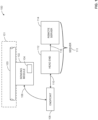
- FIG. 1 is a schematic overview of an example utility measuring system 100 in which the examples disclosed herein may be implemented.
- the utility measuring system 100 is to characterize and/or monitor a condition of a utility delivery system (e.g., a utility fluid delivery system, a utility delivery node, etc.) 101.
- the example utility measuring system 100 includes a sensing module 102 that is coupled to a pipe 103 (of the utility delivery system 101) and includes an analysis module 104, and a first bi-directional communication link 106 that communicatively couples the sensing module 102 to an endpoint (e.g., a utility measuring endpoint, a communication endpoint, a utility endpoint, etc.) 108.
- an endpoint e.g., a utility measuring endpoint, a communication endpoint, a utility endpoint, etc.
- the sensing module 102 transmits the aforementioned data packet to the endpoint 108 via the bi-directional communication link 106 and, in turn, the endpoint 108 transmits this data packet to the server 111 via the bi-directional communication link 110.
- the head end 112 then forwards the data packet to the remote server 114.
- FIG. 2 is a transparent view illustrating the example sensing module 102 of the example utility measuring system 100 of FIG. 1 .
- the sensing module 102 of the illustrated example includes a housing 202, the bi-directional communication link 106, a coupler (e.g., a pipe clamp) 204 and a pipe fitting (e.g., a pipe clamp, a coupling section, etc.) 206 that is coupled to the pipe (e.g., a utility pipe, a water pipe, etc.) 103.
- a coupler e.g., a pipe clamp
- a pipe fitting e.g., a pipe clamp, a coupling section, etc.
- the coupler 204 aligns, secures and/or couples the sensing module 102 and/or the housing 202 to the pipe fitting 206 so that measurements or recordings related to the pipe 103 and/or the overall fluid delivery/utility system 101 may be performed or directed by the sensing module 102.
- fluid In operation, fluid generally flows along a longitudinal length of the pipe 103 and through the pipe fitting 206 in this example.
- the example sensing module 102 records and/or analyzes data (e.g., spectral data) related to this fluid flow to characterize an operating condition of the utility delivery/consumption system 101.
- data associated with this recording which may be in the form of a data packet (e.g., a spectral data packet, a packet that includes compressed data), is transmitted to the endpoint 108 of FIG. 1 .
- the communication link 106 of the illustrated example provides power to the sensing module 102 and may be used to provide commands to and/or control operation of the sensing module 102.
- the sensing module 102 may be directed by the endpoint 108, the head end 112 and/or the remote server 114 to increase a polling/sensing rate and/or enter a low power mode, for example.
- the housing 202 is substantially environmentally sealed (e.g., hermetically sealed). Additionally or alternatively, the housing 202 may be sealed to the coupler 204 in some examples. In other examples, the sensing module 102 is directly coupled to the pipe 103 or is defined in the fitting 206.
- the recording may be converted (e.g., transformed) to a spectral representation to characterize the vibrational and/or acoustic signal over a frequency domain (e.g., relating amplitude of the vibrational and/or acoustic signal to frequency).
- the recording may be converted from a time-domain sample to a frequency domain.
- circuitry of the circuit board 308 which includes the analysis module 104 shown in FIG. 1 , receives a plurality of baseline recordings measured at the sensor 310.
- the circuit board 308 utilizes this plurality of baseline recordings to be converted to corresponding spectral representations for generating a baseline spectral average and/or baseline noise signature.
- the baseline spectral average is transmitted to the remote server 114 as a first data packet.
- the circuit board 308 stores the aforementioned known signature, which may be received and/or downloaded from the remote server 114. Additionally or alternatively, the baseline spectral average is subtracted from the current spectral average prior to making this comparison. In some examples, the current spectral average is compared to historical spectral averages and/or recordings.
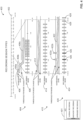
- FIG. 4 is a plot 400 representing example signal acquisition and analysis in accordance with the teachings of this disclosure.
- adaptive sampling of obtaining recordings that is performed by the sensor 310 to enable the circuit board 308 to generate a spectral average (e.g., a spectral noise signature), which may be used to define a baseline spectral average or a current spectral average, over different recording session types is demonstrated.
- the example plot 400 also illustrates example sensor initiation that may be implemented in the examples disclosed herein.
- a legend 401 representing signal recording classifications and a time scale 402 representing a time of day are shown.
- a first example recording session 404 is shown over a portion of the time scale 402.
- a signal plot (e.g., a measured plot, a measured recording, a recorded section, etc.) 406 of recording measurements is characterized by its regions or portions 406a, 406b and 406c.
- the signal plot 406 exhibits relatively flat behavior.
- the signal plot 406 decreases and crosses a threshold (e.g., a set point) and/or threshold range, and generally levels out and/or flattens along the region 406c.
- a threshold e.g., a set point
- the associated data and/or recording session data is converted to and/or analyzed within the frequency domain to define at least one spectral representation.
- associated spectral energy is examined and may be weighted to an array of the following values: [-1 0 1], for example.
- the corresponding spectral representation and/or recording is given a weighting value close to 0 (e.g., a value of 0). Accordingly, higher spectral energy recordings and/or corresponding spectral representations may be weighted with a positive value while, in contrast, lower spectral energy recordings and/or corresponding spectral representations may be weighted with a negative value.
- fault-indicating recordings indicating abnormal operation, improper installation and/or misplacement of the sensor 310 and/or the sensing module 102 trigger a warning and/or flag to indicate that the recording obtained are faulty and/or may result in generation of faulty spectral representations and/or averages. Additionally or alternatively, these fault indicating recordings may trigger a reset of the sensor 310 and/or the sensing module 102.
- the difference between the current spectral average plot 506 and averaged baseline spectral plot 508 is determined and/or calculated by taking an integral of a difference between the current spectral average plot 506 and averaged baseline spectral plot 508 (e.g., an integral average of the differences).
- an integral of a difference between the current spectral average plot 506 and averaged baseline spectral plot 508 e.g., an integral average of the differences.
- sum areas of the current spectral average plot 506 and averaged baseline spectral plot 508 may be subtracted from one another to determine the difference.
- overall shapes of waveforms corresponding to the current spectral average plot 506 and the averaged baseline spectral plot 508 are compared to one another to determine this difference.
- time-domain recordings corresponding to the averaged baseline spectral plot 508 and/or the current spectral average plot 506 are processed/transformed with a fast Fourier transform (FFT) for later characterization and/or comparison.
- FFT fast Fourier transform
- a second averaged frequency plot 604b corresponds to an average including the spectral representation 602 and the spectral representation 604. However, in this example, not enough measurements have been taken to generate a fully-defined baseline spectral noise average.
- the third averaged frequency plot 606a may be used as an averaged baseline spectral average to be compared to a current spectral average to determine a leak condition.
- the third average plot 606a may define the current spectral average that is compared to another baseline spectral average.
- noise e.g., environmental noise, random noise, etc.
- the randomness of multiple recordings and/or their associated spectral representations effectively removes random noise from inherent or characteristic system noise, thereby enabling very accurate baseline or known scenario characterization. While sixteen recordings/signatures are described in this example, any appropriate number of recordings may be used based on accuracy needs and/or inherent characteristics of a respective fluid delivery system.
- different recordings and/or associated spectral representations are weighted differently.
- a recording which may be associated with a known baseline time period, historical and/or older in time, may have a greater weighting factor than later added recordings, for example.
- similar recordings and/or associated spectral representations are grouped together (e.g., assigned a particular number based on similar amplitudes and/or waveforms), thereby defining grouped recordings or representations.
- these grouped recordings or spectral representations are designated a number or label (e.g., 127) that can be incremented based on increasing amplitudes (e.g., 127+1).
- these grouped recordings or spectral representations may be averaged or normalized together to define a grouped spectral average.
- the example analysis module 104 also includes a recording or signature storage 709 and an encoder/transmitter 710 that is communicatively coupled to the spectral signal calculator 702 via a communication line 714. Further, the example encoder/transceiver 710 is communicatively coupled to the condition comparator 708 via a communication line 712. Also, the sensor 310 of FIG. 3 is shown communicatively coupled to the spectral signal pre-processor 704 via a communication line 716. Further, the encoder/transceiver 710 is communicatively coupled to the endpoint 108 via a communication line 718.
- the senor 310 of the illustrated example provides a plurality of recordings to the spectral signal pre-processor 704 so that each recording of the plurality of recordings is converted to a respective spectral representation.
- the spectral signal pre-processor 704 determines whether the spectral representations and/or the recordings meet noise and/or waveform requirements and collects a requisite number (e.g., 10-20, 100, 1000, etc.) of the recordings from the sensor 310 that are needed to generate a well-defined spectral average (e.g., a current spectral average, a baseline spectral average). Additionally or alternatively, the spectral signal pre-processor 704 directs and/or controls operating parameters of the sensor 310.
- a requisite number e.g., 10-20, 100, 1000, etc.
- the example spectral signal analyzer 706 averages multiple spectral representations by performing averaging techniques shown and described in connection with the example of FIG. 6 .
- the spectral signal analyzer 706 receives multiple spectral representations of recordings that have been sorted and/or pre-processed by the example spectral signal pre-processor 704 to generate the spectral average. Additionally or alternatively, these pre-processed recordings, the respective spectral representations and/or the generated spectral average is stored in the recording storage 709 and retrieved therefrom (e.g., retrieved to be packaged with a later measured current spectral average).
- the current spectral average is compared to a historical recording and/or spectral average to determine the leak condition. Additionally or alternatively, a previously saved recording is retrieved from the recording storage 709 and/or spectral data packets are retrieved or transmitted for leak condition determinations.
- any of the example spectral signal pre-processor 704, the example spectral signal analyzer 706, the example condition comparator 708, encoder/transmitter 710 and/or, more generally, the example analysis module 104 could be implemented by one or more analog or digital circuit(s), logic circuits, programmable processor(s), application specific integrated circuit(s) (ASIC(s)), programmable logic device(s) (PLD(s)) and/or field programmable logic device(s) (FPLD(s)).
- ASIC application specific integrated circuit
- PLD programmable logic device
- FPLD field programmable logic device
- At least one of the example, spectral signal pre-processor 704, the example spectral signal analyzer 706, the example condition comparator 708, and/or the example encoder/transmitter 710 is/are hereby expressly defined to include a tangible computer readable storage device or storage disk such as a memory, a digital versatile disk (DVD), a compact disk (CD), a Blu-ray disk, etc. storing the software and/or firmware.
- the example analysis module 104 of FIGS. 1 and 7 may include one or more elements, processes and/or devices in addition to, or instead of, those illustrated in FIG. 7 , and/or may include more than one of any or all of the illustrated elements, processes and devices.
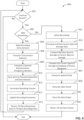
- example program is described with reference to the flowchart illustrated in FIG. 8 , many other methods of implementing the example analysis module 104 may alternatively be used. For example, the order of execution of the blocks may be changed, and/or some of the blocks described may be changed, eliminated, or combined.
- tangible computer readable storage medium and “tangible machine readable storage medium” are used interchangeably. Additionally or alternatively, the example processes of FIG. 8 may be implemented using coded instructions (e.g., computer and/or machine readable instructions) stored on a non-transitory computer and/or machine readable medium such as a hard disk drive, a flash memory, a read-only memory, a compact disk, a digital versatile disk, a cache, a random-access memory and/or any other storage device or storage disk in which information is stored for any duration (e.g., for extended time periods, permanently, for brief instances, for temporarily buffering, and/or for caching of the information).
- coded instructions e.g., computer and/or machine readable instructions
- a non-transitory computer and/or machine readable medium such as a hard disk drive, a flash memory, a read-only memory, a compact disk, a digital versatile disk, a cache, a random-access memory and/or any other storage device or storage disk in which information is
- non-transitory computer readable medium is expressly defined to include any type of computer readable storage device and/or storage disk and to exclude propagating signals and to exclude transmission media.
- phrase "at least" is used as the transition term in a preamble of a claim, it is open-ended in the same manner as the term “comprising" is open ended.
- the example method of FIG. 8 begins as the leak detection sensor 301 that has been coupled to an installation (e.g., a previously installed installation) that is currently being operated.
- the installation is being used as a node in a utility network and/or system to provide fluid (e.g., water or gas) to utility customers and a baseline spectral average has already been calculated and uploaded to the remote server 114 by the analysis module 104.
- fluid e.g., water or gas
- the spectral pre-processor 704 determines whether a session (e.g., a recording session, a characterization session, etc.) should be active (block 801). If the session is to be active and/or continue (block 801), control of the process proceeds to block 802. Otherwise, the process ends (e.g., the recording session is not continued or initiated).
- a session e.g., a recording session, a characterization session, etc.
- the spectral signal pre-processor 704 and/or the spectral signal analyzer 706 may determine whether the recordings are to be obtained. This determination may be based on whether a new spectral average is needed (e.g., whether a spectral average of the today's recordings is desired) or whether a new baseline spectral average should or needs to be defined. If additional recordings are to be added (block 802), control of the process proceeds to block 804. Otherwise, the process proceeds to block 816.
- a recording is made (block 804).
- the sensor 301 records a time domain signal/recording and/or characteristics in the time domain.
- time domain statistics of the recording are computed by the spectral signal pre-processor 704, for example (block 806).
- numerous quantitative attributes of the recording such as peaks and/or signal patterns, for example, in the time domain may be recorded and/or characterized.
- data associated with these time-domain characteristics is stored in the recording storage 709 for later transmission (e.g., encoded in a packet along with the spectral average data).
- a spectral representation of the time-domain recording is computed/calculated by the example spectral signal analyzer 706 and/or the spectral signal pre-processor 704 (block 808).
- the time domain signal recording is converted into a frequency domain recording via a transformation.
- this conversion occurs via an FFT analysis of the time domain signal, thereby defining a spectral representation.
- a power spectral density calculation is used.
- wavelet filtering is performed.
- the spectral representation and/or data associated with the spectral representation is saved (block 810).
- the spectral representation is saved onto the recording storage 709.
- a recording counter (e.g., a counter to record a number of recordings) is incremented (block 812).
- the counter is used to determine whether a minimum number of recordings have been obtained (e.g., 16 recordings, 50 recordings, etc.).
- this polling frequency may be varied based on a pipe configuration (e.g., diameter, material, coupling implementation), type of environment (e.g., residential, valve, industrial, commercial, etc.), or any appropriate environment.
- sensor 310 is directed to perform measurements at a defined time period (e.g., a few minutes, a few hours, a few days, a few months, etc.) after certain events and/or daily use patterns.
- a return/transmit recording status is transmitted by the encoder/transceiver 710, for example (block 814) and the process returns to block 801.
- recordings and/or associated spectral representations are selected and/or sorted (block 816).
- the spectral signal pre-processor 704 of the illustrated example may remove noisy spectral representations and/or append newer spectral representations.
- spectral representations are grouped by similarity (e.g., a similarity in peak amplitude and/or waveform shape, etc.).
- the spectral average is compared to a known signature from a database (block 822). This comparison may be performed to determine a leak condition.
- the database may be stored on the recording storage 709 and/or the remote server 114.
- the collected spectral average data is compressed (block 824).
- the spectral signal analyzer 706 and/or the spectral signal pre-processor 704 may perform the compression.
- an A-law compression algorithm may be used.
- the collected spectral average data is grouped with other recordings and/or categorized into a known group of recordings/spectral representation to save disk storage space.
- the compression may be performed to reduce necessary transmissions to the endpoint 108, thereby saving power and/or battery use.
- the recording storage 709 stores the data packet (block 828).
- the data packet may be stored for later transmission and/or to be combined with other data later and/or for later transmission when the leak detection sensor is turned on.
- the data packet is transmitted (block 830) and the process ends.
- the example encoder/transceiver 710 transmits the aforementioned data packet to the remote server 114 via the endpoint 108.
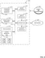
- FIG. 9 is a block diagram of an example processor platform 900 capable of executing the instructions of FIG. 8 to implement the analysis module 104 of FIGS. 1 and 7 .
- the processor platform 900 can be, for example, a server, a personal computer, a mobile device (e.g., a cell phone, a smart phone, a tablet such as an iPad TM ), a personal digital assistant (PDA), an Internet appliance, a DVD player, a CD player, a digital video recorder, a Blu-ray player, a gaming console, a personal video recorder, a set top box, or any other type of computing device.
- a mobile device e.g., a cell phone, a smart phone, a tablet such as an iPad TM
- PDA personal digital assistant
- an Internet appliance e.g., a DVD player, a CD player, a digital video recorder, a Blu-ray player, a gaming console, a personal video recorder, a set top box, or any other type of computing
- the processor platform 900 of the illustrated example includes a processor 912.
- the processor 912 of the illustrated example is hardware.
- the processor 912 can be implemented by one or more integrated circuits, logic circuits, microprocessors or controllers from any desired family or manufacturer.
- the processor 912 of the illustrated example includes a local memory 913 (e.g., a cache).
- the example processor also includes the example spectral signal pre-processor 704, the example spectral signal analyzer 706, condition comparator 708 and the encoder/transceiver 710.
- the processor 912 of the illustrated example is in communication with a main memory including a volatile memory 914 and a non-volatile memory 916 via a bus 918.
- the volatile memory 914 may be implemented by Synchronous Dynamic Random Access Memory (SDRAM), Dynamic Random Access Memory (DRAM), RAMBUS Dynamic Random Access Memory (RDRAM) and/or any other type of random access memory device.
- the non-volatile memory 916 may be implemented by flash memory and/or any other desired type of memory device. Access to the main memory 914, 916 is controlled by a memory controller.
- one or more input devices 1022 are connected to the interface circuit 920.
- the input device(s) 922 permit(s) a user to enter data and commands into the processor 912.
- the input device(s) can be implemented by, for example, an audio sensor, a microphone, a camera (still or video), a keyboard, a button, a mouse, a touchscreen, a track-pad, a trackball, isopoint and/or a voice recognition system.
- the interface circuit 920 of the illustrated example also includes a communication device such as a transmitter, a receiver, a transceiver, a modem and/or network interface card to facilitate exchange of data with external machines (e.g., computing devices of any kind) via a network 926 (e.g., an Ethernet connection, a digital subscriber line (DSL), a telephone line, coaxial cable, a cellular telephone system, etc.).
- a network 926 e.g., an Ethernet connection, a digital subscriber line (DSL), a telephone line, coaxial cable, a cellular telephone system, etc.
- the processor platform 900 of the illustrated example also includes one or more mass storage devices 928 for storing software and/or data.
- mass storage devices 928 include floppy disk drives, hard drive disks, compact disk drives, Blu-ray disk drives, RAID systems, and digital versatile disk (DVD) drives.
- the coded instructions 932 of FIG. 8 may be stored in the mass storage device 928, in the volatile memory 914, in the non-volatile memory 916, and/or on a removable tangible computer readable storage medium such as a CD or DVD.
- the above disclosed methods, apparatus and articles of manufacture provide an effective and power-efficient manner of accurately determining a leak condition by generating a spectral average based on organizing and/or analyzing multiple recordings (e.g., multiple baseline recordings).
- the generated spectral averages that are not affected by ambient and/or inherent noise characteristics of corresponding systems (e.g., utility systems) and may be compared to a current recording to determine the leak condition.
- the examples disclosed herein also enable adaptive data sampling, which can reduce power consumption, especially in battery-run devices such as some remote sensors (e.g., remote acoustic leak detection sensors) to obtain recordings.
- the disclosure comprises the following items:
Landscapes
- Physics & Mathematics (AREA)
- General Physics & Mathematics (AREA)
- Examining Or Testing Airtightness (AREA)
Applications Claiming Priority (4)
| Application Number | Priority Date | Filing Date | Title |
|---|---|---|---|
| US201762466843P | 2017-03-03 | 2017-03-03 | |
| US15/589,497 US10359335B2 (en) | 2017-03-03 | 2017-05-08 | Methods and apparatus to analyze recordings in leak detection |
| EP18710729.7A EP3589928A1 (de) | 2017-03-03 | 2018-03-01 | Verfahren und vorrichtung zur analyse von aufzeichnungen in der leckdetektion |
| PCT/US2018/020439 WO2018160826A1 (en) | 2017-03-03 | 2018-03-01 | Methods and apparatus to analyze recordings in leak detection |
Related Parent Applications (1)
| Application Number | Title | Priority Date | Filing Date |
|---|---|---|---|
| EP18710729.7A Division EP3589928A1 (de) | 2017-03-03 | 2018-03-01 | Verfahren und vorrichtung zur analyse von aufzeichnungen in der leckdetektion |
Publications (2)
| Publication Number | Publication Date |
|---|---|
| EP4538667A2 true EP4538667A2 (de) | 2025-04-16 |
| EP4538667A3 EP4538667A3 (de) | 2025-05-07 |
Family
ID=63355269
Family Applications (2)
| Application Number | Title | Priority Date | Filing Date |
|---|---|---|---|
| EP24222885.6A Pending EP4538667A3 (de) | 2017-03-03 | 2018-03-01 | Verfahren und vorrichtung zur analyse von aufzeichnungen bei der leckdetektion |
| EP18710729.7A Ceased EP3589928A1 (de) | 2017-03-03 | 2018-03-01 | Verfahren und vorrichtung zur analyse von aufzeichnungen in der leckdetektion |
Family Applications After (1)
| Application Number | Title | Priority Date | Filing Date |
|---|---|---|---|
| EP18710729.7A Ceased EP3589928A1 (de) | 2017-03-03 | 2018-03-01 | Verfahren und vorrichtung zur analyse von aufzeichnungen in der leckdetektion |
Country Status (5)
| Country | Link |
|---|---|
| US (2) | US10359335B2 (de) |
| EP (2) | EP4538667A3 (de) |
| AU (2) | AU2018228866B2 (de) |
| CA (1) | CA3055191C (de) |
| WO (1) | WO2018160826A1 (de) |
Families Citing this family (13)
| Publication number | Priority date | Publication date | Assignee | Title |
|---|---|---|---|---|
| US10359335B2 (en) * | 2017-03-03 | 2019-07-23 | Itron, Inc. | Methods and apparatus to analyze recordings in leak detection |
| US10527516B2 (en) * | 2017-11-20 | 2020-01-07 | Phyn Llc | Passive leak detection for building water supply |
| US11248981B2 (en) | 2017-11-21 | 2022-02-15 | Itron, Inc. | Methods and apparatus to detect leaks based on temperature data |
| DE102018009822A1 (de) * | 2018-12-14 | 2020-06-18 | Diehl Metering S.A.S. | Verfahren zum Sammeln von Daten, Sensor sowie Versorgungsnetz |
| AU2020262969B2 (en) * | 2019-04-24 | 2023-12-14 | Adelaide university | Detection of structural anomalies in a pipeline network |
| CN114008417B (zh) * | 2019-06-21 | 2024-11-08 | 沃特洛电气制造公司 | 用于预测和控制气体管线性能的系统和方法 |
| US11519812B2 (en) | 2019-09-12 | 2022-12-06 | Flow International Corporation | Acoustic emissions monitoring of high pressure systems |
| WO2021127754A1 (pt) | 2019-12-27 | 2021-07-01 | Companhia De Saneamento Básico Do Estado De São Paulo - Sabesp | Método e bancada de simulação de sinais de vazamento em duto |
| US12098630B2 (en) * | 2020-02-04 | 2024-09-24 | Halliburton Energy Services, Inc. | Movement noise suppression in a moving array for downhole leakage localization |
| JP7630340B2 (ja) * | 2021-04-12 | 2025-02-17 | アズビル金門株式会社 | 内管漏洩判定装置及び内管漏洩判定方法 |
| US11788919B2 (en) | 2021-10-08 | 2023-10-17 | Itron, Inc. | Coordinated acoustic leak detection sensor sampling |
| US20240118124A1 (en) * | 2022-10-10 | 2024-04-11 | Arad Measuring Technologies Ltd. | Method and Apparatus to Determine Utility Usage |
| KR102811607B1 (ko) * | 2023-06-13 | 2025-05-21 | 엘지전자 주식회사 | 냉매누설검지장치 및 이를 포함하는 공기조화기 |
Family Cites Families (21)
| Publication number | Priority date | Publication date | Assignee | Title |
|---|---|---|---|---|
| US5038614A (en) | 1989-08-10 | 1991-08-13 | Atlantic Richfield Company | Acoustic vibration detection of fluid leakage from conduits |
| US7949495B2 (en) * | 1996-03-28 | 2011-05-24 | Rosemount, Inc. | Process variable transmitter with diagnostics |
| US5974862A (en) * | 1997-05-06 | 1999-11-02 | Flow Metrix, Inc. | Method for detecting leaks in pipelines |
| US6567006B1 (en) | 1999-11-19 | 2003-05-20 | Flow Metrix, Inc. | Monitoring vibrations in a pipeline network |
| US6453247B1 (en) * | 2000-01-14 | 2002-09-17 | National Research Council Of Canada | PC multimedia-based leak detection system for water transmission and distribution pipes |
| US6957157B2 (en) | 2002-11-12 | 2005-10-18 | Flow Metrix, Inc. | Tracking vibrations in a pipeline network |
| FR2910619B1 (fr) | 2006-12-21 | 2009-05-08 | Cybernetix Sa | Systeme de detection et de localisation d'un evenement dans une canalisation de transport de fluide permettant l'utilisation de moyens de communication de faible bande passante |
| US7705721B1 (en) | 2007-03-13 | 2010-04-27 | Network Appliance, Inc. | Apparatus and method for sensing and responding to environmental conditions of a computer system at non-uniform polling intervals |
| US7918126B2 (en) * | 2007-09-26 | 2011-04-05 | Fmc Technologies, Inc. | Intelligent underwater leak detection system |
| US8643716B1 (en) | 2008-02-13 | 2014-02-04 | Power Survey Llc | Method and system for mobile steam leak detection |
| US7711500B1 (en) | 2008-10-24 | 2010-05-04 | General Electric Company | Pressure relief valve monitoring |
| NO330636B1 (no) | 2009-02-23 | 2011-05-30 | Roxar Flow Measurement As | Anordning og fremgangsmate for akustikkbasert sandovervaking ved et rorsystem |
| US8346492B2 (en) | 2009-10-21 | 2013-01-01 | Acoustic Systems, Inc. | Integrated acoustic leak detection system using intrusive and non-intrusive sensors |
| US20150330863A1 (en) | 2011-05-16 | 2015-11-19 | Triple Plus | Method and System for Identifying Leaks in Fluid Pipe Construction |
| US9772250B2 (en) | 2011-08-12 | 2017-09-26 | Mueller International, Llc | Leak detector and sensor |
| US20130101127A1 (en) | 2011-10-21 | 2013-04-25 | Research In Motion Limited | System and method for changing an activation state of an electronic device using acoustic signals |
| KR101447925B1 (ko) | 2013-08-22 | 2014-10-08 | 주식회사 엘지씨엔에스 | 누출 신호 분석 방법 |
| WO2016185435A1 (en) | 2015-05-21 | 2016-11-24 | Saipem S.P.A. | System and method for real time remote measurement of geometric parameters of a pipeline in the launch step, through sound waves |
| EP3389478B1 (de) | 2015-12-15 | 2021-03-31 | Mayo Foundation for Medical Education and Research | Systeme und verfahren zum linearen zeitlichen clustering für begrenzte, wiederholbare, seltene ereignisse in physiologischen signalen |
| US10473270B2 (en) | 2016-09-30 | 2019-11-12 | General Electric Company | Leak detection user interfaces |
| US10359335B2 (en) * | 2017-03-03 | 2019-07-23 | Itron, Inc. | Methods and apparatus to analyze recordings in leak detection |
-
2017
- 2017-05-08 US US15/589,497 patent/US10359335B2/en active Active
-
2018
- 2018-03-01 AU AU2018228866A patent/AU2018228866B2/en active Active
- 2018-03-01 EP EP24222885.6A patent/EP4538667A3/de active Pending
- 2018-03-01 CA CA3055191A patent/CA3055191C/en active Active
- 2018-03-01 EP EP18710729.7A patent/EP3589928A1/de not_active Ceased
- 2018-03-01 WO PCT/US2018/020439 patent/WO2018160826A1/en not_active Ceased
-
2019
- 2019-05-29 US US16/424,725 patent/US10704982B2/en active Active
-
2020
- 2020-09-30 AU AU2020244485A patent/AU2020244485B2/en active Active
Also Published As
| Publication number | Publication date |
|---|---|
| CA3055191A1 (en) | 2018-09-07 |
| AU2018228866B2 (en) | 2020-09-17 |
| US10704982B2 (en) | 2020-07-07 |
| US20180252611A1 (en) | 2018-09-06 |
| EP4538667A3 (de) | 2025-05-07 |
| AU2020244485A1 (en) | 2020-10-29 |
| US20190277722A1 (en) | 2019-09-12 |
| WO2018160826A1 (en) | 2018-09-07 |
| AU2018228866A1 (en) | 2019-10-10 |
| US10359335B2 (en) | 2019-07-23 |
| EP3589928A1 (de) | 2020-01-08 |
| CA3055191C (en) | 2022-04-26 |
| AU2020244485B2 (en) | 2022-02-10 |
Similar Documents
| Publication | Publication Date | Title |
|---|---|---|
| AU2020244485B2 (en) | Methods and apparatus to analyze recordings in leak detection | |
| US20230003881A1 (en) | Methods and apparatus to measure and analyze vibration signatures | |
| RU2488815C2 (ru) | Способ и устройство для классификации генерирующих звук процессов | |
| US12276638B2 (en) | Systems, methods, and media for generating alerts of water hammer events in steam pipes | |
| CA3080003C (en) | Methods and apparatus to detect leaks | |
| US11248981B2 (en) | Methods and apparatus to detect leaks based on temperature data | |
| CN119044980B (zh) | 风资源探测用的声雷达系统 | |
| CN118410450A (zh) | 基于云计算的按摩椅远程健康监测方法 | |
| Liguori et al. | Towards the evaluation of the measurement uncertainty of environmental acoustic noise | |
| CN120254593A (zh) | Gis局部放电在线监测方法 | |
| JP3693644B2 (ja) | 設備の運転状態音響監視方法および設備の運転状態音響監視装置 | |
| JP2002323371A (ja) | 音響診断装置及び音響診断方法 | |
| CN120557149A (zh) | 一种气体压缩机运行状态监测方法及系统 | |
| JPH03235027A (ja) | 異常検出装置 | |
| CN211477587U (zh) | 在线安全预警装置和故障诊断系统 | |
| US20250050355A1 (en) | Method for controlling a centrifuge and centrifuge | |
| CA3173473A1 (en) | Systems, methods, and media for generating alerts of water hammer events in steam pipes | |
| CN120369829B (zh) | 一种用于六面顶压机的监测方法及系统 | |
| KR102785610B1 (ko) | 초음파 유량 측정에서 수신 신호를 교정하는 장치 및 방법 | |
| CN121577259A (zh) | 一种面向变压器油箱生产的泄漏检测方法及系统 | |
| CN118349937A (zh) | 一种术后引流袋的流速异常检测方法及系统 | |
| CN121679256A (zh) | 电表箱故障检测方法、系统及电子设备 | |
| CN121323977A (zh) | 一种蒸汽轮机离合器齿轮啮合噪声在线采集系统及方法 | |
| CN120477766A (zh) | 智能手环的血氧监测提醒方法、智能手环、介质与产品 | |
| CN121256221A (zh) | 基于多模态信号的液压加载系统检测方法及系统 |
Legal Events
| Date | Code | Title | Description |
|---|---|---|---|
| PUAI | Public reference made under article 153(3) epc to a published international application that has entered the european phase |
Free format text: ORIGINAL CODE: 0009012 |
|
| STAA | Information on the status of an ep patent application or granted ep patent |
Free format text: STATUS: THE APPLICATION HAS BEEN PUBLISHED |
|
| PUAL | Search report despatched |
Free format text: ORIGINAL CODE: 0009013 |
|
| AC | Divisional application: reference to earlier application |
Ref document number: 3589928 Country of ref document: EP Kind code of ref document: P |
|
| AK | Designated contracting states |
Kind code of ref document: A2 Designated state(s): AL AT BE BG CH CY CZ DE DK EE ES FI FR GB GR HR HU IE IS IT LI LT LU LV MC MK MT NL NO PL PT RO RS SE SI SK SM TR |
|
| AK | Designated contracting states |
Kind code of ref document: A3 Designated state(s): AL AT BE BG CH CY CZ DE DK EE ES FI FR GB GR HR HU IE IS IT LI LT LU LV MC MK MT NL NO PL PT RO RS SE SI SK SM TR |
|
| RIC1 | Information provided on ipc code assigned before grant |
Ipc: G01M 3/28 20060101ALI20250331BHEP Ipc: G01M 3/00 20060101ALI20250331BHEP Ipc: G01M 3/24 20060101AFI20250331BHEP |
|
| STAA | Information on the status of an ep patent application or granted ep patent |
Free format text: STATUS: REQUEST FOR EXAMINATION WAS MADE |
|
| 17P | Request for examination filed |
Effective date: 20250916 |