EP4538565A1 - Electrically driven valve - Google Patents
Electrically driven valve Download PDFInfo
- Publication number
- EP4538565A1 EP4538565A1 EP24199490.4A EP24199490A EP4538565A1 EP 4538565 A1 EP4538565 A1 EP 4538565A1 EP 24199490 A EP24199490 A EP 24199490A EP 4538565 A1 EP4538565 A1 EP 4538565A1
- Authority
- EP
- European Patent Office
- Prior art keywords
- cylindrical portion
- diameter
- valve
- orifice
- valve element
- Prior art date
- Legal status (The legal status is an assumption and is not a legal conclusion. Google has not performed a legal analysis and makes no representation as to the accuracy of the status listed.)
- Pending
Links
Images




Classifications
-
- F—MECHANICAL ENGINEERING; LIGHTING; HEATING; WEAPONS; BLASTING
- F16—ENGINEERING ELEMENTS AND UNITS; GENERAL MEASURES FOR PRODUCING AND MAINTAINING EFFECTIVE FUNCTIONING OF MACHINES OR INSTALLATIONS; THERMAL INSULATION IN GENERAL
- F16K—VALVES; TAPS; COCKS; ACTUATING-FLOATS; DEVICES FOR VENTING OR AERATING
- F16K31/00—Actuating devices; Operating means; Releasing devices
- F16K31/02—Actuating devices; Operating means; Releasing devices electric; magnetic
- F16K31/06—Actuating devices; Operating means; Releasing devices electric; magnetic using a magnet, e.g. diaphragm valves, cutting off by means of a liquid
- F16K31/0644—One-way valve
- F16K31/0655—Lift valves
-
- F—MECHANICAL ENGINEERING; LIGHTING; HEATING; WEAPONS; BLASTING
- F16—ENGINEERING ELEMENTS AND UNITS; GENERAL MEASURES FOR PRODUCING AND MAINTAINING EFFECTIVE FUNCTIONING OF MACHINES OR INSTALLATIONS; THERMAL INSULATION IN GENERAL
- F16K—VALVES; TAPS; COCKS; ACTUATING-FLOATS; DEVICES FOR VENTING OR AERATING
- F16K1/00—Lift valves or globe valves, i.e. cut-off apparatus with closure members having at least a component of their opening and closing motion perpendicular to the closing faces
- F16K1/32—Details
- F16K1/34—Cutting-off parts, e.g. valve members, seats
-
- F—MECHANICAL ENGINEERING; LIGHTING; HEATING; WEAPONS; BLASTING
- F16—ENGINEERING ELEMENTS AND UNITS; GENERAL MEASURES FOR PRODUCING AND MAINTAINING EFFECTIVE FUNCTIONING OF MACHINES OR INSTALLATIONS; THERMAL INSULATION IN GENERAL
- F16K—VALVES; TAPS; COCKS; ACTUATING-FLOATS; DEVICES FOR VENTING OR AERATING
- F16K1/00—Lift valves or globe valves, i.e. cut-off apparatus with closure members having at least a component of their opening and closing motion perpendicular to the closing faces
- F16K1/32—Details
- F16K1/54—Arrangements for modifying the way in which the rate of flow varies during the actuation of the valve
Definitions
- the present invention relates to an electrically driven valve.
- valve opening control in which fluid is flown by a low flow rate by maintaining a minute opening state of the valve that is realized immediately after opening the valve. Even during such a minute opening state, it is necessary to suppress fluctuation of flow rate of fluid passing through an orifice.
- an electrically driven valve in which an inner circumference of the orifice has a long and narrow cylindrical shape, and an outer circumference of the valve element disposed within the orifice also has a long and narrow cylinder shape.
- an electrically driven valve in a case where the valve element is relatively displaced in an axial direction with respect to the orifice, a cross-sectional area of the flow path of a gap formed between the orifice and the valve element is constant until the valve element is withdrawn from the orifice, such that the flow rate control of fluid passing through the gap may be performed stably.
- the present technique enables to provide an electrically driven valve that may be processed easily and that requires lower costs, while still ensuring desired flow rate characteristics.
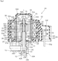
- FIG. 1 is a vertical cross-sectional view illustrating an electrically driven valve 1 according to the first embodiment.
- FIG. 2 is a view schematically illustrating a periphery of an orifice portion and a valve element portion of the electrically driven valve 1, wherein a part thereof is not shown in the drawing.
- An axis of the electrically driven valve 1 is denoted by L. According further to the present specification, a direction from a rotor toward a valve seat is called downward, and a direction opposite thereto is called upward.
- a flange-like plate 18 is fixed by brazing etc. to an upper end portion of the valve main body 10.
- a lower end portion of the can 55 having a cylindrical shape with a top portion is abutted against a stepped portion provided on an outer circumference of the flange-like plate 18, and joined thereto in a sealed manner by welding.
- the rotor 51 arranged within the can 55 is fit to and supported by the valve shaft holder 30, and the valve shaft holder 30 is designed to rotate integrally with the rotor 51.
- the rotor 51 adopts a duplex tube configuration composed of an inner tube 51a, an outer tube 51b, and a connecting portion 51c that connects the inner tube 51a and the outer tube 51b at a predetermined angular position about the axis L, wherein a plurality of vertical grooves 51d that extend in the axis L direction, i.e., up-down direction, are formed at an angular interval of 120 degrees about the axis L on the inner circumference of the inner tube 51a.
- a plurality of ribs 30a that extend in the up-down direction at an angular interval of 120 degrees about the axis L are formed in a protruded manner on the upper half portion of the outer circumference of the valve shaft holder 30.
- a locking surface (not shown) facing upward and supporting the rotor 51 is formed on both sides at the lower portion of the ribs 30a.
- the rotor 51 By having the vertical grooves 51d on the inner tube 51a of the rotor 51 engage with the ribs 30a of the valve shaft holder 30, and having the lower surface of the inner tube 51a of the rotor 51 abut against the locking surface of the valve shaft holder 30, the rotor 51 is supported and fixed in a state positioned against the valve shaft holder 30. Thereby, the valve shaft holder 30 rotates together with the rotor 51 while supporting the rotor 51 within the can 55.
- An upper portion of the locking member 70 is externally fit to an upper end portion of an upper small-diameter portion 41 of the valve shaft 40 and fixed thereto by press fitting, welding, or the like.
- a flange-shaped rotor presser 72 is disposed at a lower portion of the locking member 70. The rotor 51 is nipped between the rotor presser 72 and the valve shaft holder 30 that is urged upward by the urging force of the compression coil spring 60.
- a return spring 75 composed of a coil spring is externally disposed on an outer circumference of the locking member 70.
- the return spring 75 urges the valve shaft holder 30 toward the guide bush 20, such that if screw engagement between a male screw portion 23 of the guide bush 20 and a female screw portion 33 of the valve shaft holder 30 is disengaged by the valve shaft holder 30 being displaced upward excessively with respect to the guide bush 20 during valve opening, the screw engagement may be recovered.
- the valve shaft 40 formed of a metallic material includes, from the upper side, the upper small-diameter portion 41, an intermediate large-diameter portion 42 having a larger diameter than the upper small-diameter portion 41, and a valve element portion 43.
- the configuration of the valve element portion 43 will be described later.
- the guide bush 20 includes a thin cylindrical portion 22, a thick cylindrical portion 21, and a base portion 27, which are connected consecutively. Outer diameters of the thin cylindrical portion 22 and the thick cylindrical portion 21 are the same, and an outer diameter of the base portion 27 is greater than those.
- the intermediate large-diameter portion 42 of the valve shaft 40 is inserted and fit to the thick cylindrical portion 21 in a manner capable of moving relatively in sliding motion in the axis L direction and also capable of rotating relatively about the axis L.
- the thin cylindrical portion 22 extending upward from the upper end portion of the thick cylindrical portion 21 has a greater inner diameter than the thick cylindrical portion 21, and into which are inserted an upper end of the intermediate large-diameter portion 42 and a lower end of the upper small-diameter portion 41 of the valve shaft 40.
- a movable stopper body 34 is formed to protrude integrally from a lower end of the outer circumference of the cylindrical portion 31 of the valve shaft holder 30.
- the fixed stopper body 24 and the movable stopper body 34 that constitute the lower portion stopper mechanism 29 mutually engage with each other when the valve shaft holder 30 lowers for a predetermined amount, by which rotational lowering of the valve shaft holder 30 and the valve shaft 40 connected to the valve shaft holder 30 are limited.
- the compression coil spring, i.e., urging member, 60 is mounted in a compressed manner between an inner stepped surface formed between the upper small-diameter portion 41 and the intermediate large-diameter portion 42 of the valve shaft 40 and the lower surface of the top portion 32 of the valve shaft holder 30.
- the compression coil spring 60 urges the valve shaft 40 constantly downward, i.e., valve closing direction, with respect to the valve shaft holder 30.
- the valve main body 10 is composed of a cylindrical body made of metal such as brass SUS or the like.
- the valve main body 10 includes a valve chamber VC having fluid introduced thereto and discharged therefrom, and a first conduit T1 is connected and fixed by brazing etc. to a first opening 10a disposed laterally to an inner circumference of the valve chamber VC.
- a partition wall 11 is formed to extend inwardly in a radial direction at an intermediate position in the axis L direction of the valve main body 10, and a through hole 11a that communicates the fitting hole 14 and the valve chamber VC is formed at the center of the partition wall 11, wherein the intermediate large-diameter portion 42 of the valve shaft 40 is inserted slidably to the through hole 11a.
- An orifice portion 13 formed to correspond to the valve element portion 43 of the valve shaft 40 is formed on an inner side of a bottom wall 12 of the valve main body 10, and a second conduit T2 is connected and fixed by brazing etc. to an annular recess portion 10b formed on the lower surface of the bottom wall 12.
- the orifice portion 13 includes a first orifice cylindrical portion, i.e., small-diameter orifice cylindrical portion, 13a, a second orifice cylindrical portion, i.e., large-diameter orifice cylindrical portion, 13b formed to communicate with the upper side of the first orifice cylindrical portion 13a and having a shorter axial direction length than the first orifice cylindrical portion 13a, an upper stepped portion 13f (not shown in FIG. 2 ) having an annular shape formed on a circumference of an upper end of the second orifice cylindrical portion 13b, and an orifice tapered portion 13c that is formed to communicate with the lower side of the first orifice cylindrical portion 13a and that expands in diameter toward the downward direction.
- a first orifice cylindrical portion i.e., small-diameter orifice cylindrical portion, 13a
- a second orifice cylindrical portion i.e., large-diameter orifice cylindrical portion
- 13b formed to communicate with the upper side of
- the valve element portion 43 includes a first valve element conical portion, i.e., large-diameter tapered portion, 43a that is formed on a lower end of the intermediate large-diameter portion 42 and that shrinks in diameter toward the downward direction, a first valve element cylindrical portion, i.e., large-diameter valve element cylindrical portion, 43b that connects to the first valve element conical portion 43a, a second valve element cylindrical portion, i.e., small-diameter valve element cylindrical portion, 43d that connects to the first valve element cylindrical portion 43b and that has a longer axial direction length than the first valve element cylindrical portion 43b, and a third valve element conical portion, i.e., small-diameter tapered portion, 43e that connects to the second valve element cylindrical portion 43d.
- a first valve element conical portion i.e., large-diameter tapered portion, 43a that is formed on a lower end of the intermediate large-diameter portion 42 and that shrink
- the third valve element conical portion 43e may be a tapered portion having a two-step shape with different taper angles.
- the tapered portion is illustrated as having a one-step shape. It is preferable to have the valve element portion 43 formed by a turning process.
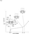
- FIG. 3 is a flow rate characteristic diagram of the electrically driven valve 1, in which the vertical axis shows a flow rate and the horizontal axis shows a valve opening, i.e., axial direction position of the valve shaft, wherein the positional relationship of the valve element portion 43 and the orifice portion 13 are illustrated schematically.
- the valve opening is proportional to a drive pulse of a control signal applied to the stator coil 52c.
- the position P0 of FIG. 3 corresponds to a limiting position
- a position having exceeded the position P0 of FIG. 3 corresponds to an open position.
- the electrically driven valve 1 is in a valve closed state illustrated in FIG. 1 , and the first valve element conical portion 43a of the valve element portion 43 is seated on the valve seat 13d, i.e., the position P0 of FIG. 3 .
- the second valve element cylindrical portion 43d is positioned on the inner side in the radial direction, i.e., superposed in the axial direction, of the first orifice cylindrical portion 13a
- the first valve element cylindrical portion 43b is positioned on the inner side in the radial direction, i.e., superposed in the axial direction, of the second orifice cylindrical portion 13b.
- valve shaft holder 30 and the valve shaft 40 rotate integrally therewith. This rotation is converted by the screw feeding mechanism 28 into an axial direction displacement of the valve shaft 40, and the valve shaft 40 is elevated together with the valve element portion 43.
- the second valve element cylindrical portion 43d is displaced in the axial direction with respect to the first orifice cylindrical portion 13a, and the first valve element cylindrical portion 43b is displaced in the axial direction with respect to the second orifice cylindrical portion 13b.
- the first valve element conical portion 43a and the valve seat 13d are separated and a minimum gap exceeding 0 is created, such that fluid such as a refrigerant etc. is passed through from the valve chamber VC via the minimum gap and between the valve element portion 43 and the orifice portion 13 to be flown into the second conduit T2.
- the first valve element cylindrical portion 43b is withdrawn from the second orifice cylindrical portion 13b, i.e., the first valve element cylindrical portion 43b will no longer be positioned on the inner side in the radial direction of the second orifice cylindrical portion 13b, such that the gap between the first valve element cylindrical portion 43b and the second orifice cylindrical portion 13b will no longer lead to pressure drop.
- the throttle region is still the area corresponding to the gap between the second valve element cylindrical portion 43d and the first orifice cylindrical portion 13a.
- the second valve element cylindrical portion 43d and the first orifice cylindrical portion 13a are relatively displaced in the axis L direction, such that the superposed areas are gradually narrowed, and the pressure drop between the valve element portion 43 and the orifice portion 13 is further reduced, such that the flow rate of fluid passing through the throttle region is gradually increased, which corresponds from the position P2 to the position P3 of FIG. 3 .
- the increase rate of flow rate is greater from the position P2 to the position P3 than that from the position P 1 to the position P2 in FIG. 3 .
- the second valve element cylindrical portion 43d is withdrawn from the first orifice cylindrical portion 13a, i.e., the second valve element cylindrical portion 43d will no longer be positioned on the inner side in the radial direction of the first orifice cylindrical portion 13a, such that thereafter, the portion corresponding to the gap between the third valve element conical portion 43e and the upper end of the first orifice cylindrical portion 13a will serve as the throttle region, and as the valve shaft 40 elevates, the flow rate of fluid passing through between the valve element portion 43 and the orifice portion 13 will be increased linearly, such that flow rate adjustment is enabled. Thereafter, the valve shaft 40 is elevated until a valve fully opened state (not shown) is reached.
- valve shaft holder 30 and the valve shaft 40 are rotated integrally therewith, and the movement is converted by the screw feeding mechanism 28 into the axial direction displacement of the valve shaft 40, such that the valve shaft 40 is lowered together with the valve element portion 43 until the valve closed state illustrated in FIG. 1 is reached.
- FIG. 4 is a cross-sectional view illustrating a periphery of an orifice portion 13' and a valve element portion 43' of a valve element 40' according to a comparative example.
- the valve element portion 43' includes a first valve element conical portion 43a', a valve element cylindrical portion 43b', and a second valve element conical portion 43c'.
- the orifice portion 13' includes an orifice cylindrical portion 13a' and a valve seat 13d'.
- the distance from the contact between the valve seat 13d' and the first valve element conical portion 43a' to the lower end of the valve element cylindrical portion 43b' is denote by A3. It is preferable if A1 ⁇ A2 ⁇ A3 is satisfied, and it is preferable if A1 + A2 ⁇ A3 is satisfied.
- valve element cylindrical portion 43b' and the orifice cylindrical portion 13a' are both formed by cutting, there is a dispersion caused by component tolerance in the cross-sectional area ⁇ 3.
- the length of the drill used for cutting the orifice cylindrical portion 13a' is elongated compared to the diameter, the processing difficulty is increased.
- the orifice portion 13 includes the first orifice cylindrical portion 13a and the second orifice cylindrical portion 13b, such that the length of the drill for cutting the first orifice cylindrical portion 13a may be shortened, and the processing becomes easy, according to which yield is improved. Further, the number of drive pulses from the valve closed state to a point of time at which the first valve element cylindrical portion 43b withdraws from the second orifice cylindrical portion 13b, i.e., the position P2 of FIG. 3 , may be reduced, such that the flow rate control becomes easy.
- FIG. 5 is a vertical cross-sectional view illustrating an electrically driven valve 1A according to a second embodiment.
- FIG. 6 is a flow rate characteristic diagram of the electrically driven valve 1A, wherein the vertical axis shows a flow rate and the horizontal axis shows a valve opening, i.e., axial direction position of the valve shaft, wherein the positional relationship between a valve element portion 43A and an orifice portion 13A is illustrated schematically.
- the electrically driven valve 1A according to the present embodiment is a valve that does not close completely, so-called a non-closing type valve, wherein only the valve element portion 43A of a valve shaft 40A and the orifice portion 13A of a valve main body 10A differ from the first embodiment.
- the orifice portion 13A includes a first orifice cylindrical portion 13Aa, a second orifice cylindrical portion 13Ab that is formed to communicate with the upper side of the first orifice cylindrical portion 13Aa and having a shorter axial direction length than the first orifice cylindrical portion 13Aa, an upper stepped portion 13Af having an annular shape formed on a circumference of an upper end of the second orifice cylindrical portion 13Ab, and an orifice tapered portion 13Ac that is formed to communicate with the lower side of the first orifice cylindrical portion 13Aa and that expands in diameter toward the downward direction.
- the intersection between the first orifice cylindrical portion 13Aa and the upper stepped portion 13Af does not constitute a valve seat.
- valve element portion 43A includes a first valve element cylindrical portion 43Ab that connects to a lower end of the intermediate large-diameter portion 42 of the valve shaft 40A, a second valve element cylindrical portion 43Ad that connects to the first valve element cylindrical portion 43Ab and that has a longer axial direction length than the first valve element cylindrical portion 43Ab, and a third valve element conical portion 43Ae that connects to the second valve element cylindrical portion 43Ad.
- the third valve element conical portion 43Ae may be a tapered portion having a two-step shape with different taper angles.
- a first valve element conical portion is not formed between the intermediate large-diameter portion 42 and the first valve element cylindrical portion 43Ab, and a boundary between the two portions is a stepped surface 43Af.
- the electrically driven valve 1A When the electrically driven valve 1A is in a minimum valve opened state illustrated in FIG. 5 , corresponding to positions P4 to P5 in FIG. 6 , the stepped surface 43Af and a bottom wall 12A will not come into contact with one another, and a predetermined gap is formed therebetween.
- the second valve element cylindrical portion 43Ad is positioned on an inner side in the radial direction of the first orifice cylindrical portion 13Aa
- the first valve element cylindrical portion 43Ab is positioned on an inner side in the radial direction of the second orifice cylindrical portion 13Ab.
- a throttle portion between the valve element portion 43A and the orifice portion 13A is a portion corresponding to the gap between the second valve element cylindrical portion 43Ad and the first orifice cylindrical portion 13Aa. Therefore, change of flow rate will not occur even if the valve shaft 40A is elevated from the position P4 of FIG. 6 , i.e., minimum valve opened state, to the position P5 where reduction of pressure drop of the valve element portion 43A and the orifice portion 13A starts. Thereafter, the configuration is similar to the first embodiment.
- the first valve element cylindrical portion 43Ab is withdrawn from the second orifice cylindrical portion 13Ab, i.e., the first valve element cylindrical portion 43Ab will no longer be positioned on the inner side in the radial direction of the second orifice cylindrical portion 13Ab, and at the position P7 illustrated in FIG.
- the second valve element cylindrical portion 43Ad is withdrawn from the first orifice cylindrical portion 13Aa, i.e., the second valve element cylindrical portion 43Ad will no longer be positioned on the inner side in the radial direction of the first orifice cylindrical portion 13Aa, such that together with the elevation of the valve shaft 40A, similar to the first embodiment, the flow rate of the fluid passing through the valve element portion 43A and the orifice portion 13A is increased.
- the gap between the second valve element cylindrical portion 43Ad and the first orifice cylindrical portion 13Aa forms a throttle region until the second valve element cylindrical portion 43Ad is withdrawn from the inner side in the radial direction of the first orifice cylindrical portion 13Aa.
- the present invention is not limited to the embodiments described above. Modifications of arbitrary components of the embodiments described above is enabled within the scope of the present invention. Further, adding or deleting of arbitrary components of the embodiments described above is enabled.
- An electrically driven valve includes
- valve element portion includes a large-diameter tapered portion
- the orifice portion includes a valve seat, and in the limiting position, the large-diameter tapered portion is seated on the valve seat.
Landscapes
- Engineering & Computer Science (AREA)
- General Engineering & Computer Science (AREA)
- Mechanical Engineering (AREA)
- Electrically Driven Valve-Operating Means (AREA)
Abstract
Description
- The present invention relates to an electrically driven valve.
- Heretofore, electrically driven valves are arranged on a piping route of fluid and used as an equipment for opening and closing or for performing flow rate control of the flow path of fluid. In such electrically driven valves, accurate flow rate control is ensured by driving a valve element using a driving source, such as a stepping motor, disposed on a valve main body, as described in
Japanese Patent Application Laid-Open Publication No. 2017-180525 - In electrically driven valves, it may be required to perform a valve opening control, in which fluid is flown by a low flow rate by maintaining a minute opening state of the valve that is realized immediately after opening the valve. Even during such a minute opening state, it is necessary to suppress fluctuation of flow rate of fluid passing through an orifice.
- In order to ensure a stable flow rate control in the minute opening state, there has been developed an electrically driven valve in which an inner circumference of the orifice has a long and narrow cylindrical shape, and an outer circumference of the valve element disposed within the orifice also has a long and narrow cylinder shape. In such an electrically driven valve, in a case where the valve element is relatively displaced in an axial direction with respect to the orifice, a cross-sectional area of the flow path of a gap formed between the orifice and the valve element is constant until the valve element is withdrawn from the orifice, such that the flow rate control of fluid passing through the gap may be performed stably.
- However, in order to realize the configuration described above, it is necessary to form the inner circumference of the orifice and the outer circumference of the valve element opposed thereto to have a highly accurate cylindrical shape across a certain length, which requires time-consuming processing and may lead to increase of costs of the electrically driven valve.
- The present invention aims at providing an electrically driven valve that may be processed easily and that requires lower costs, while still ensuring desired flow rate characteristics.
- The electrically driven valve according to the present technique characterizes in including
- a valve main body including a valve chamber and an orifice portion,
- a valve shaft that is inserted to the orifice portion and that includes a valve element portion, and
- a valve shaft driving portion configured to displace the valve shaft with respect to the valve main body between a limiting position where a flow rate of fluid passing through the orifice portion is smallest and an open position where a flow rate of fluid passing through the orifice portion is increased compared to the limiting position,
- wherein the valve element portion includes a large-diameter valve element cylindrical portion, a small-diameter valve element cylindrical portion having a smaller diameter than the large-diameter valve element cylindrical portion, and a small-diameter tapered portion that is formed continuously to the small-diameter valve element cylindrical portion,
- wherein the orifice portion includes a small-diameter orifice cylindrical portion, and a large-diameter orifice cylindrical portion having a greater diameter than the small-diameter orifice cylindrical portion,
- wherein, in a state where the valve shaft is at the limiting position, the small-diameter valve element cylindrical portion is positioned on an inner side in a radial direction of the small-diameter orifice cylindrical portion and the large-diameter valve element cylindrical portion is positioned on an inner side in a radial direction of the large-diameter orifice cylindrical portion, and
- wherein, in a state where the valve shaft is displaced from the limiting position to the open position, after the large-diameter valve element cylindrical portion has been withdrawn from the inner side in the radial direction of the large-diameter orifice, the small-diameter valve element cylindrical portion is withdrawn from the inner side in the radial direction of the small-diameter orifice cylindrical portion.
- The present technique enables to provide an electrically driven valve that may be processed easily and that requires lower costs, while still ensuring desired flow rate characteristics.
-
-
FIG. 1 is a vertical cross-sectional view illustrating an electrically driven valve according to a first embodiment. -
FIG. 2 is a view schematically illustrating a periphery of an orifice portion and a valve element portion of the electrically driven valve according to the first embodiment. -
FIG. 3 is a characteristic diagram of flow rate of the electrically driven valve according to the first embodiment, wherein a vertical axis shows a flow rate and a horizontal axis shows a valve opening, i.e., axial direction position of a valve shaft. -
FIG. 4 is a cross-sectional view illustrating a periphery of a valve element portion and an orifice portion according to a comparative example illustrated in comparison withFIG. 2 . -
FIG. 5 is a view schematically illustrating a periphery of an orifice portion and a valve element portion of an electrically driven valve according to a second embodiment. -
FIG. 6 is a flow rate characteristic diagram of the electrically driven valve according to the second embodiment, wherein the vertical axis shows a flow rate and the horizontal axis shows a valve opening, i.e., axial direction position of a valve shaft. - Embodiments of an electrically driven valve according to the present invention will be described below with reference to the drawings.
-
FIG. 1 is a vertical cross-sectional view illustrating an electrically drivenvalve 1 according to the first embodiment.FIG. 2 is a view schematically illustrating a periphery of an orifice portion and a valve element portion of the electrically drivenvalve 1, wherein a part thereof is not shown in the drawing. An axis of the electrically drivenvalve 1 is denoted by L. According further to the present specification, a direction from a rotor toward a valve seat is called downward, and a direction opposite thereto is called upward. - In
FIG. 1 , the electrically drivenvalve 1 is equipped with a valvemain body 10, aguide bush 20, avalve shaft holder 30, avalve shaft 40, acan 55, astepping motor 50 composed of arotor 51 and astator 52, a compression coil spring, i.e., urging member, 60, alocking member 70, ascrew feeding mechanism 28, and a lowerportion stopper mechanism 29. In the present embodiment, thestepping motor 50 and thescrew feeding mechanism 28 constitute a valve shaft driving portion. - A flange-
like plate 18 is fixed by brazing etc. to an upper end portion of the valvemain body 10. A lower end portion of thecan 55 having a cylindrical shape with a top portion is abutted against a stepped portion provided on an outer circumference of the flange-like plate 18, and joined thereto in a sealed manner by welding. - The
rotor 51 is rotatably arranged on an inner side of thecan 55 and on an outer side of theguide bush 20 and thevalve shaft holder 30, and thestator 52 for driving therotor 51 to rotate is arranged on an outer side of thecan 55. Thestator 52 is composed of ayoke 52a, abobbin 52b, astator coil 52c, and aresin mold cover 52d etc. Thestator coil 52c receives input of a control signal including a drive pulse from an exterior via aboard 52f to which alead wire 52g is connected, and therotor 51 arranged within thecan 55 is driven to rotate about an axis L according to an angle corresponding to the drive pulse by excitation of thestator coil 52c. - The
rotor 51 arranged within thecan 55 is fit to and supported by thevalve shaft holder 30, and thevalve shaft holder 30 is designed to rotate integrally with therotor 51. - Specifically, the
rotor 51 adopts a duplex tube configuration composed of aninner tube 51a, anouter tube 51b, and a connectingportion 51c that connects theinner tube 51a and theouter tube 51b at a predetermined angular position about the axis L, wherein a plurality ofvertical grooves 51d that extend in the axis L direction, i.e., up-down direction, are formed at an angular interval of 120 degrees about the axis L on the inner circumference of theinner tube 51a. - A plurality of
ribs 30a that extend in the up-down direction at an angular interval of 120 degrees about the axis L are formed in a protruded manner on the upper half portion of the outer circumference of thevalve shaft holder 30. A locking surface (not shown) facing upward and supporting therotor 51 is formed on both sides at the lower portion of theribs 30a. - By having the
vertical grooves 51d on theinner tube 51a of therotor 51 engage with theribs 30a of thevalve shaft holder 30, and having the lower surface of theinner tube 51a of therotor 51 abut against the locking surface of thevalve shaft holder 30, therotor 51 is supported and fixed in a state positioned against thevalve shaft holder 30. Thereby, thevalve shaft holder 30 rotates together with therotor 51 while supporting therotor 51 within thecan 55. - The
locking member 70 having a tubular shape that prevents relative movement of thevalve shaft holder 30 and therotor 51 in the lifting and lowering direction, is disposed on an upper side of therotor 51 and thevalve shaft holder 30. Thelocking member 70 pushes therotor 51 downward against thevalve shaft holder 30, and connects thevalve shaft 40 and thevalve shaft holder 30. - An upper portion of the
locking member 70 is externally fit to an upper end portion of an upper small-diameter portion 41 of thevalve shaft 40 and fixed thereto by press fitting, welding, or the like. A flange-shaped rotor presser 72 is disposed at a lower portion of thelocking member 70. Therotor 51 is nipped between therotor presser 72 and thevalve shaft holder 30 that is urged upward by the urging force of thecompression coil spring 60. A height in an up-down direction of thevalve shaft holder 30 from an upper end to the locking surface is the same height in the up-down direction of theinner tube 51a of therotor 51, and an upper surface of atop portion 32 of thevalve shaft holder 30 is abutted against a lower surface of therotor presser 72. - A
return spring 75 composed of a coil spring is externally disposed on an outer circumference of thelocking member 70. Thereturn spring 75 urges the valve shaft holder 30 toward theguide bush 20, such that if screw engagement between amale screw portion 23 of theguide bush 20 and afemale screw portion 33 of thevalve shaft holder 30 is disengaged by thevalve shaft holder 30 being displaced upward excessively with respect to theguide bush 20 during valve opening, the screw engagement may be recovered. - The
valve shaft 40 formed of a metallic material includes, from the upper side, the upper small-diameter portion 41, an intermediate large-diameter portion 42 having a larger diameter than the upper small-diameter portion 41, and avalve element portion 43. The configuration of thevalve element portion 43 will be described later. - The
guide bush 20 includes a thincylindrical portion 22, a thickcylindrical portion 21, and abase portion 27, which are connected consecutively. Outer diameters of the thincylindrical portion 22 and the thickcylindrical portion 21 are the same, and an outer diameter of thebase portion 27 is greater than those. The intermediate large-diameter portion 42 of thevalve shaft 40 is inserted and fit to the thickcylindrical portion 21 in a manner capable of moving relatively in sliding motion in the axis L direction and also capable of rotating relatively about the axis L. The thincylindrical portion 22 extending upward from the upper end portion of the thickcylindrical portion 21 has a greater inner diameter than the thickcylindrical portion 21, and into which are inserted an upper end of the intermediate large-diameter portion 42 and a lower end of the upper small-diameter portion 41 of thevalve shaft 40. - The
male screw portion 23 is formed on an outer circumference of the thickcylindrical portion 21 of theguide bush 20. Further, thebase portion 27, which is a lower portion of the thickcylindrical portion 21 below themale screw portion 23 is fit by press fitting to afitting hole 14 of the valvemain body 10. Alower stopper 25 is fixed by screw-engagement on a side below thevalve shaft holder 30 of themale screw portion 23 with a predetermined clearance from anupper surface 27a of thebase portion 27. A fixedstopper body 24 is integrally formed to protrude from the outer circumference of thelower stopper 25. - The
valve shaft holder 30 includes acylindrical portion 31 into which theguide bush 20 is inserted, and thetop portion 32. Thetop portion 32 is penetratingly provided with aninsertion hole 32a to which an upper end portion of the upper small-diameter portion 41 of thevalve shaft 40 is inserted. Thefemale screw portion 33 being engaged with themale screw portion 23 of theguide bush 20 and constituting thescrew feeding mechanism 28, is formed on an inner circumference of thecylindrical portion 31 of thevalve shaft holder 30. Thescrew feeding mechanism 28 is a mechanism that converts a rotational displacement of therotor 51 with respect to the valvemain body 10 into an axial direction displacement of thevalve shaft 40. - A
movable stopper body 34 is formed to protrude integrally from a lower end of the outer circumference of thecylindrical portion 31 of thevalve shaft holder 30. The fixedstopper body 24 and themovable stopper body 34 that constitute the lowerportion stopper mechanism 29 mutually engage with each other when thevalve shaft holder 30 lowers for a predetermined amount, by which rotational lowering of thevalve shaft holder 30 and thevalve shaft 40 connected to thevalve shaft holder 30 are limited. - Further, the compression coil spring, i.e., urging member, 60 is mounted in a compressed manner between an inner stepped surface formed between the upper small-
diameter portion 41 and the intermediate large-diameter portion 42 of thevalve shaft 40 and the lower surface of thetop portion 32 of thevalve shaft holder 30. Thecompression coil spring 60 urges thevalve shaft 40 constantly downward, i.e., valve closing direction, with respect to thevalve shaft holder 30. - The valve
main body 10 is composed of a cylindrical body made of metal such as brass SUS or the like. The valvemain body 10 includes a valve chamber VC having fluid introduced thereto and discharged therefrom, and a first conduit T1 is connected and fixed by brazing etc. to afirst opening 10a disposed laterally to an inner circumference of the valve chamber VC. Apartition wall 11 is formed to extend inwardly in a radial direction at an intermediate position in the axis L direction of the valvemain body 10, and a throughhole 11a that communicates thefitting hole 14 and the valve chamber VC is formed at the center of thepartition wall 11, wherein the intermediate large-diameter portion 42 of thevalve shaft 40 is inserted slidably to the throughhole 11a. - An
orifice portion 13 formed to correspond to thevalve element portion 43 of thevalve shaft 40 is formed on an inner side of abottom wall 12 of the valvemain body 10, and a second conduit T2 is connected and fixed by brazing etc. to anannular recess portion 10b formed on the lower surface of thebottom wall 12. - In
FIG. 3 , theorifice portion 13 includes a first orifice cylindrical portion, i.e., small-diameter orifice cylindrical portion, 13a, a second orifice cylindrical portion, i.e., large-diameter orifice cylindrical portion, 13b formed to communicate with the upper side of the first orificecylindrical portion 13a and having a shorter axial direction length than the first orificecylindrical portion 13a, an upper steppedportion 13f (not shown inFIG. 2 ) having an annular shape formed on a circumference of an upper end of the second orificecylindrical portion 13b, and an orifice taperedportion 13c that is formed to communicate with the lower side of the first orificecylindrical portion 13a and that expands in diameter toward the downward direction. Avalve seat 13d is formed at an intersection between the first orificecylindrical portion 13a and the upper steppedportion 13f. It is preferable to form the first orificecylindrical portion 13a by cutting using a drill etc., and to form the second orificecylindrical portion 13b etc. having a larger diameter using a milling cutter etc., that is, by a separate processing. - Meanwhile, the
valve element portion 43 includes a first valve element conical portion, i.e., large-diameter tapered portion, 43a that is formed on a lower end of the intermediate large-diameter portion 42 and that shrinks in diameter toward the downward direction, a first valve element cylindrical portion, i.e., large-diameter valve element cylindrical portion, 43b that connects to the first valve elementconical portion 43a, a second valve element cylindrical portion, i.e., small-diameter valve element cylindrical portion, 43d that connects to the first valve elementcylindrical portion 43b and that has a longer axial direction length than the first valve elementcylindrical portion 43b, and a third valve element conical portion, i.e., small-diameter tapered portion, 43e that connects to the second valve elementcylindrical portion 43d. The third valve elementconical portion 43e may be a tapered portion having a two-step shape with different taper angles. InFIG. 2 , the tapered portion is illustrated as having a one-step shape. It is preferable to have thevalve element portion 43 formed by a turning process. - Now, if an outer diameter of the second valve element
cylindrical portion 43d is denoted byB 1 and an inner diameter of the first orificecylindrical portion 13a is denoted by B2, a cross-sectional area Δ1 of a gap between the second valve elementcylindrical portion 43d and the first orificecylindrical portion 13a may be expressed as Δ1 = π ((B2)2 - (B1)2)/4. - Further, if an outer diameter of the first valve element
cylindrical portion 43b is denoted by B3 and an inner diameter of the second orificecylindrical portion 13b is denoted by B4, a cross-sectional area Δ2 of a gap between the first valve elementcylindrical portion 43b and the second orificecylindrical portion 13b may be expressed as Δ2 = π((B4)2 - (B3)2)/4. It is preferable that Δ1 < Δ2 is satisfied. - Further, when closing the valve, if a distance from a contact between the
valve seat 13d and the first valve elementconical portion 43a to a lower end of the first valve elementcylindrical portion 43b, is denoted by A1, and a distance from an upper end of the second orificecylindrical portion 13b to a lower end of the second valve elementcylindrical portion 43d, is denoted by A2, it is preferable that A1 ≤ A2 is satisfied. - The operation of the electrically driven
valve 1 will be described.FIG. 3 is a flow rate characteristic diagram of the electrically drivenvalve 1, in which the vertical axis shows a flow rate and the horizontal axis shows a valve opening, i.e., axial direction position of the valve shaft, wherein the positional relationship of thevalve element portion 43 and theorifice portion 13 are illustrated schematically. The valve opening is proportional to a drive pulse of a control signal applied to thestator coil 52c. According to the present embodiment, the position P0 ofFIG. 3 corresponds to a limiting position, and a position having exceeded the position P0 ofFIG. 3 corresponds to an open position. Further, immediately before the large-diameter valve element cylindrical portion is withdrawn from an inner side in the radial direction of the large-diameter orifice cylindrical portion, the lower end of the large-diameter valve element cylindrical portion is positioned on the inner side in the radial direction of the large-diameter orifice cylindrical portion. Further, immediately before the small-diameter valve element cylindrical portion is withdrawn from the small-diameter orifice cylindrical portion, a lower end of the small-diameter valve element cylindrical portion is positioned on the inner side in the radial direction of the small-diameter orifice cylindrical portion. - It is assumed that the electrically driven
valve 1 is in a valve closed state illustrated inFIG. 1 , and the first valve elementconical portion 43a of thevalve element portion 43 is seated on thevalve seat 13d, i.e., the position P0 ofFIG. 3 . In this state, the second valve elementcylindrical portion 43d is positioned on the inner side in the radial direction, i.e., superposed in the axial direction, of the first orificecylindrical portion 13a, and the first valve elementcylindrical portion 43b is positioned on the inner side in the radial direction, i.e., superposed in the axial direction, of the second orificecylindrical portion 13b. In this state, when a control signal including a drive pulse is supplied to excite thestator coil 52c of thestator 52 and therotor 51 rotates in one direction, thevalve shaft holder 30 and thevalve shaft 40 rotate integrally therewith. This rotation is converted by thescrew feeding mechanism 28 into an axial direction displacement of thevalve shaft 40, and thevalve shaft 40 is elevated together with thevalve element portion 43. - By the elevation of the
valve shaft 40, the second valve elementcylindrical portion 43d is displaced in the axial direction with respect to the first orificecylindrical portion 13a, and the first valve elementcylindrical portion 43b is displaced in the axial direction with respect to the second orificecylindrical portion 13b. Thereby, the first valve elementconical portion 43a and thevalve seat 13d are separated and a minimum gap exceeding 0 is created, such that fluid such as a refrigerant etc. is passed through from the valve chamber VC via the minimum gap and between thevalve element portion 43 and theorifice portion 13 to be flown into the second conduit T2. In a state where the minimum gap between the first valve elementconical portion 43a and thevalve seat 13d is small, i.e., from the position P0 to the position P1 ofFIG. 3 , the region where the gap is narrowest between thevalve element portion 43 and theorifice portion 13, that is, the region where the flow path cross-sectional area is smallest, which is called a throttle region, is the portion corresponding to the minimum gap between the first valve elementconical portion 43a and thevalve seat 13d, such that as the minimum gap increases, the flow rate of the fluid passing therethrough is increased linearly. - When the flow path cross-sectional area at the minimum gap between the first valve element
conical portion 43a and thevalve seat 13d exceeds the cross-sectional area Δ1 (the position P1 ofFIG. 3 ), the throttle region between thevalve element portion 43 and theorifice portion 13 becomes the portion corresponding to the gap between the second valve elementcylindrical portion 43d and the first orificecylindrical portion 13a. Since both the outer circumference of the second valve elementcylindrical portion 43d and the inner circumference of the first orificecylindrical portion 13a are cylindrical, even when thevalve shaft 40 is eccentrically displaced, the cross-sectional area Δ1 in the throttle region does not change. However, when the second valve elementcylindrical portion 43d and the first orificecylindrical portion 13a are relatively displaced in the axis L direction and the first valve elementcylindrical portion 43b and the second orificecylindrical portion 13b are relatively displaced in the axis L direction, the respectively superposed areas are gradually narrowed, and thereby, the pressure drop between thevalve element portion 43 and theorifice portion 13 is gradually reduced, such that the flow rate of fluid passing through the throttle region is gradually increased, which corresponds to the range from the position P1 to the position P2 ofFIG. 3 . - In the position P2 illustrated in
FIG. 3 , the first valve elementcylindrical portion 43b is withdrawn from the second orificecylindrical portion 13b, i.e., the first valve elementcylindrical portion 43b will no longer be positioned on the inner side in the radial direction of the second orificecylindrical portion 13b, such that the gap between the first valve elementcylindrical portion 43b and the second orificecylindrical portion 13b will no longer lead to pressure drop. However, at this point of time, since the second valve elementcylindrical portion 43d is not withdrawn from the first orificecylindrical portion 13a, i.e., the second valve elementcylindrical portion 43d is positioned on the inner side in the radial direction of the first orificecylindrical portion 13a, the throttle region is still the area corresponding to the gap between the second valve elementcylindrical portion 43d and the first orificecylindrical portion 13a. Therefore, by the elevation of thevalve shaft 40, the second valve elementcylindrical portion 43d and the first orificecylindrical portion 13a are relatively displaced in the axis L direction, such that the superposed areas are gradually narrowed, and the pressure drop between thevalve element portion 43 and theorifice portion 13 is further reduced, such that the flow rate of fluid passing through the throttle region is gradually increased, which corresponds from the position P2 to the position P3 ofFIG. 3 . Due to the difference in pressure drop of theorifice portion 13, the increase rate of flow rate is greater from the position P2 to the position P3 than that from theposition P 1 to the position P2 inFIG. 3 . - In the position P3 illustrated in
FIG. 3 , the second valve elementcylindrical portion 43d is withdrawn from the first orificecylindrical portion 13a, i.e., the second valve elementcylindrical portion 43d will no longer be positioned on the inner side in the radial direction of the first orificecylindrical portion 13a, such that thereafter, the portion corresponding to the gap between the third valve elementconical portion 43e and the upper end of the first orificecylindrical portion 13a will serve as the throttle region, and as thevalve shaft 40 elevates, the flow rate of fluid passing through between thevalve element portion 43 and theorifice portion 13 will be increased linearly, such that flow rate adjustment is enabled. Thereafter, thevalve shaft 40 is elevated until a valve fully opened state (not shown) is reached. - In contrast, from the valve fully opened state, when a control signal of a reverse characteristic is supplied to excite the
stator coil 52c of thestator 52, and therotor 51 is rotated in the opposite direction, thevalve shaft holder 30 and thevalve shaft 40 are rotated integrally therewith, and the movement is converted by thescrew feeding mechanism 28 into the axial direction displacement of thevalve shaft 40, such that thevalve shaft 40 is lowered together with thevalve element portion 43 until the valve closed state illustrated inFIG. 1 is reached. -
FIG. 4 is a cross-sectional view illustrating a periphery of an orifice portion 13' and a valve element portion 43' of a valve element 40' according to a comparative example. InFIG. 4 , the valve element portion 43' includes a first valve elementconical portion 43a', a valve elementcylindrical portion 43b', and a second valve element conical portion 43c'. Further, the orifice portion 13' includes an orificecylindrical portion 13a' and avalve seat 13d'. - Further, in a state where an outer diameter of the valve element
cylindrical portion 43b' is denoted by B5 and an inner diameter of the orificecylindrical portion 13a' is denoted by B6, a cross-sectional area Δ3 of a gap between the valve elementcylindrical portion 43b' and the orificecylindrical portion 13a' may be expressed as Δ3 = π((B6)2 - (B5)2)/4. It is preferable if Δ2 > Δ1 > Δ3 is satisfied. - Further, when closing the valve, the distance from the contact between the
valve seat 13d' and the first valve elementconical portion 43a' to the lower end of the valve elementcylindrical portion 43b', is denote by A3. It is preferable if A1 ≤ A2 < A3 is satisfied, and it is preferable if A1 + A2 ≥ A3 is satisfied. - Now, since the valve element
cylindrical portion 43b' and the orificecylindrical portion 13a' are both formed by cutting, there is a dispersion caused by component tolerance in the cross-sectional area Δ3. In order to enable a minute amount of fluid to be flown stably through a minute opening while taking such dispersion into consideration, it is necessary to ensure a long distance A3, by which the number of drive pulses required during the minute opening is increased, such that the flow rate control becomes difficult. Further, since the length of the drill used for cutting the orificecylindrical portion 13a' is elongated compared to the diameter, the processing difficulty is increased. - In contrast, according to the present embodiment, the
orifice portion 13 includes the first orificecylindrical portion 13a and the second orificecylindrical portion 13b, such that the length of the drill for cutting the first orificecylindrical portion 13a may be shortened, and the processing becomes easy, according to which yield is improved. Further, the number of drive pulses from the valve closed state to a point of time at which the first valve elementcylindrical portion 43b withdraws from the second orificecylindrical portion 13b, i.e., the position P2 ofFIG. 3 , may be reduced, such that the flow rate control becomes easy. -
FIG. 5 is a vertical cross-sectional view illustrating an electrically drivenvalve 1A according to a second embodiment.FIG. 6 is a flow rate characteristic diagram of the electrically drivenvalve 1A, wherein the vertical axis shows a flow rate and the horizontal axis shows a valve opening, i.e., axial direction position of the valve shaft, wherein the positional relationship between avalve element portion 43A and anorifice portion 13A is illustrated schematically. The electrically drivenvalve 1A according to the present embodiment is a valve that does not close completely, so-called a non-closing type valve, wherein only thevalve element portion 43A of avalve shaft 40A and theorifice portion 13A of a valvemain body 10A differ from the first embodiment. Configurations similar to those of the first embodiment are denoted with the same reference numbers, and descriptions thereof are omitted. However, according to the present embodiment, positions P4 to P5 ofFIG. 6 correspond to the limiting position, and positions exceeding the position P5 ofFIG. 6 correspond to the open position. - The
orifice portion 13A includes a first orifice cylindrical portion 13Aa, a second orifice cylindrical portion 13Ab that is formed to communicate with the upper side of the first orifice cylindrical portion 13Aa and having a shorter axial direction length than the first orifice cylindrical portion 13Aa, an upper stepped portion 13Af having an annular shape formed on a circumference of an upper end of the second orifice cylindrical portion 13Ab, and an orifice tapered portion 13Ac that is formed to communicate with the lower side of the first orifice cylindrical portion 13Aa and that expands in diameter toward the downward direction. However, according to the present embodiment, the intersection between the first orifice cylindrical portion 13Aa and the upper stepped portion 13Af does not constitute a valve seat. - Meanwhile, the
valve element portion 43A includes a first valve element cylindrical portion 43Ab that connects to a lower end of the intermediate large-diameter portion 42 of thevalve shaft 40A, a second valve element cylindrical portion 43Ad that connects to the first valve element cylindrical portion 43Ab and that has a longer axial direction length than the first valve element cylindrical portion 43Ab, and a third valve element conical portion 43Ae that connects to the second valve element cylindrical portion 43Ad. The third valve element conical portion 43Ae may be a tapered portion having a two-step shape with different taper angles. However, a first valve element conical portion is not formed between the intermediate large-diameter portion 42 and the first valve element cylindrical portion 43Ab, and a boundary between the two portions is a stepped surface 43Af. - When the electrically driven
valve 1A is in a minimum valve opened state illustrated inFIG. 5 , corresponding to positions P4 to P5 inFIG. 6 , the stepped surface 43Af and abottom wall 12A will not come into contact with one another, and a predetermined gap is formed therebetween. In this state, the second valve element cylindrical portion 43Ad is positioned on an inner side in the radial direction of the first orifice cylindrical portion 13Aa, and the first valve element cylindrical portion 43Ab is positioned on an inner side in the radial direction of the second orifice cylindrical portion 13Ab. Therefore, a throttle portion between thevalve element portion 43A and theorifice portion 13A is a portion corresponding to the gap between the second valve element cylindrical portion 43Ad and the first orifice cylindrical portion 13Aa. Therefore, change of flow rate will not occur even if thevalve shaft 40A is elevated from the position P4 ofFIG. 6 , i.e., minimum valve opened state, to the position P5 where reduction of pressure drop of thevalve element portion 43A and theorifice portion 13A starts. Thereafter, the configuration is similar to the first embodiment. - When the
valve shaft 40A is elevated even further, similar to the first embodiment, at the position P6 illustrated inFIG. 6 , the first valve element cylindrical portion 43Ab is withdrawn from the second orifice cylindrical portion 13Ab, i.e., the first valve element cylindrical portion 43Ab will no longer be positioned on the inner side in the radial direction of the second orifice cylindrical portion 13Ab, and at the position P7 illustrated inFIG. 6 , the second valve element cylindrical portion 43Ad is withdrawn from the first orifice cylindrical portion 13Aa, i.e., the second valve element cylindrical portion 43Ad will no longer be positioned on the inner side in the radial direction of the first orifice cylindrical portion 13Aa, such that together with the elevation of thevalve shaft 40A, similar to the first embodiment, the flow rate of the fluid passing through thevalve element portion 43A and theorifice portion 13A is increased. - That is, when the
valve shaft 40A is displaced from the limiting position to the open position, i.e., from the position P5 towards the position P7, the gap between the second valve element cylindrical portion 43Ad and the first orifice cylindrical portion 13Aa forms a throttle region until the second valve element cylindrical portion 43Ad is withdrawn from the inner side in the radial direction of the first orifice cylindrical portion 13Aa. - The present invention is not limited to the embodiments described above. Modifications of arbitrary components of the embodiments described above is enabled within the scope of the present invention. Further, adding or deleting of arbitrary components of the embodiments described above is enabled.
- The present specification includes the following disclosures of the present invention.
- An electrically driven valve includes
- a valve main body including a valve chamber and an orifice portion,
- a valve shaft that is inserted to the orifice portion and that includes a valve element portion, and
- a valve shaft driving portion configured to displace the valve shaft with respect to the valve main body between a limiting position where a flow rate of fluid passing through the orifice portion is smallest and an open position where a flow rate of fluid passing through the orifice portion is increased compared to the limiting position,
- wherein the valve element portion includes a large-diameter valve element cylindrical portion, a small-diameter valve element cylindrical portion having a smaller diameter than the large-diameter valve element cylindrical portion, and a small-diameter tapered portion that is formed continuously to the small-diameter valve element cylindrical portion,
- wherein the orifice portion includes a small-diameter orifice cylindrical portion, and a large-diameter orifice cylindrical portion having a greater diameter than the small-diameter orifice cylindrical portion,
- wherein, in a state where the valve shaft is at the limiting position, the small-diameter valve element cylindrical portion is positioned on an inner side in a radial direction of the small-diameter orifice cylindrical portion and the large-diameter valve element cylindrical portion is positioned on an inner side in a radial direction of the large-diameter orifice cylindrical portion, and
- wherein, in a state where the valve shaft is displaced from the limiting position to the open position, after the large-diameter valve element cylindrical portion has been withdrawn from the inner side in the radial direction of the large-diameter orifice, the small-diameter valve element cylindrical portion is withdrawn from the inner side in the radial direction of the small-diameter orifice cylindrical portion.
- The electrically driven valve according to the first aspect,
wherein, in a state where the valve shaft is displaced from the limiting position to the open position, after the small-diameter valve element cylindrical portion has been withdrawn from the inner side in the radial direction of the small-diameter orifice cylindrical portion, a gap between an end portion of the small-diameter orifice cylindrical portion and the small-diameter tapered portion forms a throttle region. - The electrically driven valve according to the first or second aspects,
wherein the valve element portion includes a large-diameter tapered portion, the orifice portion includes a valve seat, and in the limiting position, the large-diameter tapered portion is seated on the valve seat. - The electrically driven valve according to the third aspect,
wherein, in a state where the valve shaft is displaced from the limiting position to the open position, in a state after a flow path cross-sectional area between the small-diameter valve element cylindrical portion and the small-diameter orifice cylindrical portion exceeds a flow path cross-sectional area between the large-diameter tapered portion and the valve seat, a gap between the small-diameter valve element cylindrical portion and the small-diameter orifice cylindrical portion forms a throttle region. - The electrically driven valve according to the first or second aspects,
wherein, in the limiting position, the valve element portion is not in contact with the orifice portion. - The electrically driven valve according to the fifth aspect,
wherein, in a state where the valve shaft is displaced from the limiting position to the open position, a gap between the small-diameter valve element cylindrical portion and the small-diameter orifice cylindrical portion forms a throttle region until the small-diameter valve element cylindrical portion is withdrawn from the inner side in the radial direction of the small-diameter orifice cylindrical portion.
Claims (6)
- An electrically driven valve comprising:a valve main body including a valve chamber and an orifice portion;a valve shaft that is inserted to the orifice portion and that includes a valve element portion; anda valve shaft driving portion configured to displace the valve shaft with respect to the valve main body between a limiting position where a flow rate of fluid passing through the orifice portion is smallest and an open position where a flow rate of fluid passing through the orifice portion is increased compared to the limiting position,wherein the valve element portion includes a large-diameter valve element cylindrical portion, a small-diameter valve element cylindrical portion having a smaller diameter than the large-diameter valve element cylindrical portion, and a small-diameter tapered portion that is formed continuously to the small-diameter valve element cylindrical portion,wherein the orifice portion includes a small-diameter orifice cylindrical portion, and a large-diameter orifice cylindrical portion having a greater diameter than the small-diameter orifice cylindrical portion,wherein, in a state where the valve shaft is at the limiting position, the small-diameter valve element cylindrical portion is positioned on an inner side in a radial direction of the small-diameter orifice cylindrical portion and the large-diameter valve element cylindrical portion is positioned on an inner side in a radial direction of the large-diameter orifice cylindrical portion, andwherein, in a state where the valve shaft is displaced from the limiting position to the open position, after the large-diameter valve element cylindrical portion has been withdrawn from the inner side in the radial direction of the large-diameter orifice, the small-diameter valve element cylindrical portion is withdrawn from the inner side in the radial direction of the small-diameter orifice cylindrical portion.
- The electrically driven valve according to claim 1,
wherein, in a state where the valve shaft is displaced from the limiting position to the open position, after the small-diameter valve element cylindrical portion has been withdrawn from the inner side in the radial direction of the small-diameter orifice cylindrical portion, a gap between an end portion of the small-diameter orifice cylindrical portion and the small-diameter tapered portion forms a throttle region. - The electrically driven valve according to claim 2,
wherein the valve element portion includes a large-diameter tapered portion, the orifice portion includes a valve seat, and in the limiting position, the large-diameter tapered portion is seated on the valve seat. - The electrically driven valve according to claim 3,
wherein, in a state where the valve shaft is displaced from the limiting position to the open position, in a state after a flow path cross-sectional area between the small-diameter valve element cylindrical portion and the small-diameter orifice cylindrical portion exceeds a flow path cross-sectional area between the large-diameter tapered portion and the valve seat, a gap between the small-diameter valve element cylindrical portion and the small-diameter orifice cylindrical portion forms a throttle region. - The electrically driven valve according to claim 1 or claim 2,
wherein, in the limiting position, the valve element portion is not in contact with the orifice portion. - The electrically driven valve according to claim 5,
wherein, in a state where the valve shaft is displaced from the limiting position to the open position, a gap between the small-diameter valve element cylindrical portion and the small-diameter orifice cylindrical portion forms a throttle region until the small-diameter valve element cylindrical portion is withdrawn from the inner side in the radial direction of the small-diameter orifice cylindrical portion.
Applications Claiming Priority (1)
| Application Number | Priority Date | Filing Date | Title |
|---|---|---|---|
| JP2023176978A JP7760180B2 (en) | 2023-10-12 | 2023-10-12 | Motor-operated valve |
Publications (1)
| Publication Number | Publication Date |
|---|---|
| EP4538565A1 true EP4538565A1 (en) | 2025-04-16 |
Family
ID=92746685
Family Applications (1)
| Application Number | Title | Priority Date | Filing Date |
|---|---|---|---|
| EP24199490.4A Pending EP4538565A1 (en) | 2023-10-12 | 2024-09-10 | Electrically driven valve |
Country Status (3)
| Country | Link |
|---|---|
| EP (1) | EP4538565A1 (en) |
| JP (1) | JP7760180B2 (en) |
| CN (1) | CN119825931A (en) |
Citations (6)
| Publication number | Priority date | Publication date | Assignee | Title |
|---|---|---|---|---|
| US4213021A (en) * | 1979-01-19 | 1980-07-15 | Aeroquip Corporation | Indicating check valve |
| US4610424A (en) * | 1983-11-24 | 1986-09-09 | Bochumer Eisenhuette Heintzmann Gmbh & Co Kg | Shut-off valve |
| US6874751B2 (en) * | 2002-11-12 | 2005-04-05 | Mitsubishi Denki Kabushiki Kaisha | Electromagnetic valve |
| JP2017180525A (en) | 2016-03-28 | 2017-10-05 | 株式会社不二工機 | Motor valve and method for assembling the same |
| EP3591266A1 (en) * | 2016-08-30 | 2020-01-08 | Fujikoki Corporation | Electric valve |
| CN111946833A (en) * | 2020-08-20 | 2020-11-17 | 川北真空科技(北京)有限公司 | Flow-adjustable needle valve |
Family Cites Families (4)
| Publication number | Priority date | Publication date | Assignee | Title |
|---|---|---|---|---|
| JPS6060374A (en) * | 1983-09-14 | 1985-04-06 | Nippon Beeles- Kk | Adjusting valve |
| JP3237732B2 (en) * | 1993-12-29 | 2001-12-10 | 東京エレクトロン株式会社 | Variable opening valve device and heat treatment device for vacuum heat treatment furnace |
| JP2005351605A (en) * | 2004-06-14 | 2005-12-22 | Daikin Ind Ltd | Expansion valve and refrigeration device |
| JP6862054B2 (en) * | 2017-06-23 | 2021-04-21 | 株式会社ハーマン | Combustion gas amount control device and its driving method |
-
2023
- 2023-10-12 JP JP2023176978A patent/JP7760180B2/en active Active
-
2024
- 2024-09-05 CN CN202411239613.0A patent/CN119825931A/en active Pending
- 2024-09-10 EP EP24199490.4A patent/EP4538565A1/en active Pending
Patent Citations (6)
| Publication number | Priority date | Publication date | Assignee | Title |
|---|---|---|---|---|
| US4213021A (en) * | 1979-01-19 | 1980-07-15 | Aeroquip Corporation | Indicating check valve |
| US4610424A (en) * | 1983-11-24 | 1986-09-09 | Bochumer Eisenhuette Heintzmann Gmbh & Co Kg | Shut-off valve |
| US6874751B2 (en) * | 2002-11-12 | 2005-04-05 | Mitsubishi Denki Kabushiki Kaisha | Electromagnetic valve |
| JP2017180525A (en) | 2016-03-28 | 2017-10-05 | 株式会社不二工機 | Motor valve and method for assembling the same |
| EP3591266A1 (en) * | 2016-08-30 | 2020-01-08 | Fujikoki Corporation | Electric valve |
| CN111946833A (en) * | 2020-08-20 | 2020-11-17 | 川北真空科技(北京)有限公司 | Flow-adjustable needle valve |
Also Published As
| Publication number | Publication date |
|---|---|
| JP7760180B2 (en) | 2025-10-27 |
| CN119825931A (en) | 2025-04-15 |
| JP2025067203A (en) | 2025-04-24 |
Similar Documents
| Publication | Publication Date | Title |
|---|---|---|
| EP3366957B1 (en) | Electric valve | |
| JP6461872B2 (en) | Motorized valve | |
| JP6757996B2 (en) | Solenoid valve | |
| CN113324054B (en) | Electric valve | |
| CN108779871B (en) | Motor-driven valve | |
| EP1724460A1 (en) | Motor-operated valve | |
| US10253903B2 (en) | Motor-operated valve | |
| EP3620728A1 (en) | Motor operated valve | |
| JP2009264530A (en) | Motor operated valve | |
| CN112997028A (en) | Flow path switching valve | |
| EP3929476B1 (en) | Flow rate control valve | |
| EP4040086A1 (en) | Flow control valve | |
| CN111954776B (en) | Electric valve | |
| JP2021148280A (en) | Motor valve | |
| JP7760180B2 (en) | Motor-operated valve | |
| CN110345292B (en) | Electric valve | |
| JP7072907B2 (en) | Solenoid valve | |
| JP2024014977A (en) | electric valve | |
| CN216742878U (en) | Electronic expansion valve | |
| CN116792506A (en) | Electric valve and method for assembling electric valve | |
| CN115467983A (en) | Electric valve | |
| EP4382787A1 (en) | Solenoid valve | |
| CN115596843A (en) | Electronic expansion valve | |
| JP2025043403A (en) | Motor-operated valve | |
| JP2018200113A (en) | Motor-operated valve |
Legal Events
| Date | Code | Title | Description |
|---|---|---|---|
| PUAI | Public reference made under article 153(3) epc to a published international application that has entered the european phase |
Free format text: ORIGINAL CODE: 0009012 |
|
| STAA | Information on the status of an ep patent application or granted ep patent |
Free format text: STATUS: THE APPLICATION HAS BEEN PUBLISHED |
|
| AK | Designated contracting states |
Kind code of ref document: A1 Designated state(s): AL AT BE BG CH CY CZ DE DK EE ES FI FR GB GR HR HU IE IS IT LI LT LU LV MC ME MK MT NL NO PL PT RO RS SE SI SK SM TR |
|
| STAA | Information on the status of an ep patent application or granted ep patent |
Free format text: STATUS: REQUEST FOR EXAMINATION WAS MADE |
|
| 17P | Request for examination filed |
Effective date: 20250516 |
|
| GRAP | Despatch of communication of intention to grant a patent |
Free format text: ORIGINAL CODE: EPIDOSNIGR1 |
|
| STAA | Information on the status of an ep patent application or granted ep patent |
Free format text: STATUS: GRANT OF PATENT IS INTENDED |
|
| INTG | Intention to grant announced |
Effective date: 20260202 |
|
| RIC1 | Information provided on ipc code assigned before grant |
Ipc: F16K 1/54 20060101AFI20260123BHEP Ipc: F16K 31/06 20060101ALI20260123BHEP |
|
| GRAS | Grant fee paid |
Free format text: ORIGINAL CODE: EPIDOSNIGR3 |
|
| GRAA | (expected) grant |
Free format text: ORIGINAL CODE: 0009210 |
|
| STAA | Information on the status of an ep patent application or granted ep patent |
Free format text: STATUS: THE PATENT HAS BEEN GRANTED |