EP4538559A1 - Unit - Google Patents
Unit Download PDFInfo
- Publication number
- EP4538559A1 EP4538559A1 EP23821877.0A EP23821877A EP4538559A1 EP 4538559 A1 EP4538559 A1 EP 4538559A1 EP 23821877 A EP23821877 A EP 23821877A EP 4538559 A1 EP4538559 A1 EP 4538559A1
- Authority
- EP
- European Patent Office
- Prior art keywords
- gear
- axis
- disposed
- electric machine
- rotating electric
- Prior art date
- Legal status (The legal status is an assumption and is not a legal conclusion. Google has not performed a legal analysis and makes no representation as to the accuracy of the status listed.)
- Pending
Links
Images

Classifications
-
- H—ELECTRICITY
- H02—GENERATION; CONVERSION OR DISTRIBUTION OF ELECTRIC POWER
- H02K—DYNAMO-ELECTRIC MACHINES
- H02K7/00—Arrangements for handling mechanical energy structurally associated with dynamo-electric machines, e.g. structural association with mechanical driving motors or auxiliary dynamo-electric machines
- H02K7/10—Structural association with clutches, brakes, gears, pulleys or mechanical starters
- H02K7/116—Structural association with clutches, brakes, gears, pulleys or mechanical starters with gears
-
- F—MECHANICAL ENGINEERING; LIGHTING; HEATING; WEAPONS; BLASTING
- F16—ENGINEERING ELEMENTS AND UNITS; GENERAL MEASURES FOR PRODUCING AND MAINTAINING EFFECTIVE FUNCTIONING OF MACHINES OR INSTALLATIONS; THERMAL INSULATION IN GENERAL
- F16H—GEARING
- F16H57/00—General details of gearing
- F16H57/04—Features relating to lubrication or cooling or heating
- F16H57/048—Type of gearings to be lubricated, cooled or heated
- F16H57/0493—Gearings with spur or bevel gears
- F16H57/0494—Gearings with spur or bevel gears with variable gear ratio or for reversing rotary motion
-
- B—PERFORMING OPERATIONS; TRANSPORTING
- B60—VEHICLES IN GENERAL
- B60K—ARRANGEMENT OR MOUNTING OF PROPULSION UNITS OR OF TRANSMISSIONS IN VEHICLES; ARRANGEMENT OR MOUNTING OF PLURAL DIVERSE PRIME-MOVERS IN VEHICLES; AUXILIARY DRIVES FOR VEHICLES; INSTRUMENTATION OR DASHBOARDS FOR VEHICLES; ARRANGEMENTS IN CONNECTION WITH COOLING, AIR INTAKE, GAS EXHAUST OR FUEL SUPPLY OF PROPULSION UNITS IN VEHICLES
- B60K1/00—Arrangement or mounting of electrical propulsion units
-
- F—MECHANICAL ENGINEERING; LIGHTING; HEATING; WEAPONS; BLASTING
- F16—ENGINEERING ELEMENTS AND UNITS; GENERAL MEASURES FOR PRODUCING AND MAINTAINING EFFECTIVE FUNCTIONING OF MACHINES OR INSTALLATIONS; THERMAL INSULATION IN GENERAL
- F16H—GEARING
- F16H1/00—Toothed gearings for conveying rotary motion
- F16H1/02—Toothed gearings for conveying rotary motion without gears having orbital motion
- F16H1/20—Toothed gearings for conveying rotary motion without gears having orbital motion involving more than two intermeshing members
-
- F—MECHANICAL ENGINEERING; LIGHTING; HEATING; WEAPONS; BLASTING
- F16—ENGINEERING ELEMENTS AND UNITS; GENERAL MEASURES FOR PRODUCING AND MAINTAINING EFFECTIVE FUNCTIONING OF MACHINES OR INSTALLATIONS; THERMAL INSULATION IN GENERAL
- F16H—GEARING
- F16H57/00—General details of gearing
- F16H57/02—Gearboxes; Mounting gearing therein
- F16H57/021—Shaft support structures, e.g. partition walls, bearing eyes, casing walls or covers with bearings
-
- F—MECHANICAL ENGINEERING; LIGHTING; HEATING; WEAPONS; BLASTING
- F16—ENGINEERING ELEMENTS AND UNITS; GENERAL MEASURES FOR PRODUCING AND MAINTAINING EFFECTIVE FUNCTIONING OF MACHINES OR INSTALLATIONS; THERMAL INSULATION IN GENERAL
- F16H—GEARING
- F16H57/00—General details of gearing
- F16H57/02—Gearboxes; Mounting gearing therein
- F16H57/031—Gearboxes; Mounting gearing therein characterised by covers or lids for gearboxes
-
- F—MECHANICAL ENGINEERING; LIGHTING; HEATING; WEAPONS; BLASTING
- F16—ENGINEERING ELEMENTS AND UNITS; GENERAL MEASURES FOR PRODUCING AND MAINTAINING EFFECTIVE FUNCTIONING OF MACHINES OR INSTALLATIONS; THERMAL INSULATION IN GENERAL
- F16H—GEARING
- F16H57/00—General details of gearing
- F16H57/04—Features relating to lubrication or cooling or heating
- F16H57/042—Guidance of lubricant
- F16H57/0421—Guidance of lubricant on or within the casing, e.g. shields or baffles for collecting lubricant, tubes, pipes, grooves, channels or the like
- F16H57/0424—Lubricant guiding means in the wall of or integrated with the casing, e.g. grooves, channels, holes
-
- F—MECHANICAL ENGINEERING; LIGHTING; HEATING; WEAPONS; BLASTING
- F16—ENGINEERING ELEMENTS AND UNITS; GENERAL MEASURES FOR PRODUCING AND MAINTAINING EFFECTIVE FUNCTIONING OF MACHINES OR INSTALLATIONS; THERMAL INSULATION IN GENERAL
- F16H—GEARING
- F16H57/00—General details of gearing
- F16H57/04—Features relating to lubrication or cooling or heating
- F16H57/045—Lubricant storage reservoirs, e.g. reservoirs in addition to a gear sump for collecting lubricant in the upper part of a gear case
- F16H57/0453—Section walls to divide a gear sump
-
- F—MECHANICAL ENGINEERING; LIGHTING; HEATING; WEAPONS; BLASTING
- F16—ENGINEERING ELEMENTS AND UNITS; GENERAL MEASURES FOR PRODUCING AND MAINTAINING EFFECTIVE FUNCTIONING OF MACHINES OR INSTALLATIONS; THERMAL INSULATION IN GENERAL
- F16H—GEARING
- F16H57/00—General details of gearing
- F16H57/04—Features relating to lubrication or cooling or heating
- F16H57/0457—Splash lubrication
-
- F—MECHANICAL ENGINEERING; LIGHTING; HEATING; WEAPONS; BLASTING
- F16—ENGINEERING ELEMENTS AND UNITS; GENERAL MEASURES FOR PRODUCING AND MAINTAINING EFFECTIVE FUNCTIONING OF MACHINES OR INSTALLATIONS; THERMAL INSULATION IN GENERAL
- F16H—GEARING
- F16H57/00—General details of gearing
- F16H57/04—Features relating to lubrication or cooling or heating
- F16H57/0467—Elements of gearings to be lubricated, cooled or heated
- F16H57/0476—Electric machines and gearing, i.e. joint lubrication or cooling or heating thereof
-
- F—MECHANICAL ENGINEERING; LIGHTING; HEATING; WEAPONS; BLASTING
- F16—ENGINEERING ELEMENTS AND UNITS; GENERAL MEASURES FOR PRODUCING AND MAINTAINING EFFECTIVE FUNCTIONING OF MACHINES OR INSTALLATIONS; THERMAL INSULATION IN GENERAL
- F16H—GEARING
- F16H57/00—General details of gearing
- F16H57/04—Features relating to lubrication or cooling or heating
- F16H57/048—Type of gearings to be lubricated, cooled or heated
- F16H57/0482—Gearings with gears having orbital motion
- F16H57/0483—Axle or inter-axle differentials
-
- F—MECHANICAL ENGINEERING; LIGHTING; HEATING; WEAPONS; BLASTING
- F16—ENGINEERING ELEMENTS AND UNITS; GENERAL MEASURES FOR PRODUCING AND MAINTAINING EFFECTIVE FUNCTIONING OF MACHINES OR INSTALLATIONS; THERMAL INSULATION IN GENERAL
- F16H—GEARING
- F16H57/00—General details of gearing
- F16H57/04—Features relating to lubrication or cooling or heating
- F16H57/048—Type of gearings to be lubricated, cooled or heated
- F16H57/0493—Gearings with spur or bevel gears
- F16H57/0495—Gearings with spur or bevel gears with fixed gear ratio
-
- B—PERFORMING OPERATIONS; TRANSPORTING
- B60—VEHICLES IN GENERAL
- B60K—ARRANGEMENT OR MOUNTING OF PROPULSION UNITS OR OF TRANSMISSIONS IN VEHICLES; ARRANGEMENT OR MOUNTING OF PLURAL DIVERSE PRIME-MOVERS IN VEHICLES; AUXILIARY DRIVES FOR VEHICLES; INSTRUMENTATION OR DASHBOARDS FOR VEHICLES; ARRANGEMENTS IN CONNECTION WITH COOLING, AIR INTAKE, GAS EXHAUST OR FUEL SUPPLY OF PROPULSION UNITS IN VEHICLES
- B60K1/00—Arrangement or mounting of electrical propulsion units
- B60K2001/001—Arrangement or mounting of electrical propulsion units one motor mounted on a propulsion axle for rotating right and left wheels of this axle
-
- F—MECHANICAL ENGINEERING; LIGHTING; HEATING; WEAPONS; BLASTING
- F16—ENGINEERING ELEMENTS AND UNITS; GENERAL MEASURES FOR PRODUCING AND MAINTAINING EFFECTIVE FUNCTIONING OF MACHINES OR INSTALLATIONS; THERMAL INSULATION IN GENERAL
- F16H—GEARING
- F16H57/00—General details of gearing
- F16H57/02—Gearboxes; Mounting gearing therein
- F16H57/021—Shaft support structures, e.g. partition walls, bearing eyes, casing walls or covers with bearings
- F16H2057/0216—Intermediate shaft supports, e.g. by using a partition wall
Definitions
- the present invention relates to a unit.
- Patent Document 1 discloses a vehicle drive device including a counter gear mechanism for reducing a speed.
- the vehicle drive device transmits output torque of a rotating electric machine to a pair of wheels via a pair of output members to run the vehicle.
- Patent Document 1 WO 2021/131204
- a rotating electric machine can be used in combination with a power transmission mechanism such as a reduction mechanism or a differential gear.
- a power transmission mechanism such as a reduction mechanism or a differential gear.
- the rotating electric machine and the power transmission mechanism are not unitized and are provided separately, an efficient layout cannot be achieved, and as a result, an overall size may become large. Therefore, a unit with high layout properties is desired.
- the present invention has been made in consideration of such a problem, and an object thereof is to improve layout properties of a unit.
- a unit includes a housing configured to house oil, a rotating electric machine, a first gear connected downstream of the rotating electric machine, a second gear meshing with the first gear, a third gear connected downstream of the second gear, a fourth gear meshing with the third gear, a fifth gear connected downstream of the fourth gear, and a sixth gear meshing with the fifth gear.
- the rotating electric machine and the first gear are disposed on a first axis.
- the second gear and the third gear are disposed on a second axis.
- the fourth gear and the fifth gear are disposed on a third axis.
- the sixth gear is disposed on a fourth axis. When viewed in an axial direction, the first axis and the fourth axis are disposed at a lower side of the second axis and the third axis.
- a diameter of each gear can be made smaller to achieve a predetermined gear ratio.
- layout constraints caused by excessively large gears can be alleviated. Therefore, layout properties of the unit can be improved.
- by concentrating the first axis and the fourth axis on a lower side in a direction of gravity it becomes easier to guide the oil scattered by rotation of the sixth gear, which is a gear on the downstream side, to a rotating electric machine side as described above. Therefore, a layout that allows for appropriate oil lubrication is achieved.
- the unit can also be referred to as, for example, a motor unit (a unit having at least a motor) or a power transmission device (a device having at least a power transmission mechanism).
- the motor is a rotating electric machine having an electric motor function and/or a generator function (at least one of the electric motor function and the generator function).
- the power transmission mechanism is, for example, a gear mechanism and/or a differential gear mechanism.
- a device (unit) including the motor and the power transmission mechanism is included in concepts of both the motor unit and the power transmission device.
- the unit 100 includes a housing 10, a rotating electric machine 20, a reduction mechanism 30, and a differential gear 40.
- the unit 100 is mounted on a vehicle, which is an electric vehicle.
- the housing 10 includes a first cover 11, the second cover 12, and a case 13.
- the rotating electric machine 20, the reduction mechanism 30, and the differential gear 40 are housed in the housing 10.
- the first cover 11 closes an opening of the cylindrical case 13 from one side in an axial direction (left side in FIG. 1 )
- the second cover 12 closes an opening of the case 13 from the other side in an axial direction.
- the rotating electric machine 20 is housed in the case 13, and the differential gear 40 is housed in the second cover 12.
- the unit 100 has oil OL.
- the oil OL is supplied to the rotating electric machine 20 in the case 13 from the outside of the housing 10 to lubricate the rotating electric machine 20, for example.
- a part of the oil OL supplied to the rotating electric machine 20 is stored in the housing 10 and housed in the housing 10.
- the remaining oil OL is discharged to the outside of the housing 10.
- the oil OL can be used by being circulated inside and outside the housing 10.
- the rotating electric machine 20 includes the rotor 21, the stator 22, and a rotating shaft 23, and constitutes a drive source for a vehicle.
- the rotor 21 is provided on the outer periphery of the rotating shaft 23.
- the stator 22 is provided to the case 13 and houses the rotor 21.
- the rotating shaft 23 protrudes from the rotor 21 toward both sides in the axial direction.
- the rotating shaft 23 penetrates the first cover 11 at one end side in an axial direction and penetrates the case 13 at the other end side in an axial direction.
- a bearing 51 is provided on the first cover 11 at a portion through which the rotating shaft 23 penetrates, and a bearing 52 is provided on the case 13 at a portion through which the rotating shaft 23 penetrates, and the rotating shaft 23 is supported by the bearing 51 and the bearing 52.
- a resolver 80 is provided on the rotating shaft 23 at a portion protruding from the first cover 11. The resolver 80 detects the rotation of the rotating electric machine 20.
- the reduction mechanism 30 is a gear mechanism, and includes a first gear 31, a second gear 32, a third gear 33, a fourth gear 34, a fifth gear 35, a sixth gear 36, a shaft 37, and a shaft 38.
- the first gear 31 and the rotating electric machine 20 are disposed on the first axis AX1.
- the rotating electric machine 20 and the first gear 31 are disposed coaxially with respect to the first axis AX1.
- a plurality of elements (components, portions, and the like) disposed on an N-th axis (N is a natural number) is synonymous with the plurality of elements disposed coaxially with respect to the N-th axis.
- the first axis AX1, the second axis AX2, the third axis AX3, and the fourth axis AX4 all constitute axes of the unit 100 and extend in the same direction. Therefore, the extension directions of the first axis AX1, the second axis AX2, the third axis AX3, and the fourth axis AX4 all correspond to the axial direction of the unit 100. That is, the axial direction means an axial direction of the rotating shaft of components (for example, the motor, the gear mechanism, and the differential gear mechanism) that constitute the unit.
- the first gear 31 is connected downstream of the rotating electric machine 20.
- the downstream is a power output side, and the rotor 21 and the stator 22 that generate power are used as references for the rotating electric machine 20. Therefore, the downstream of the rotating electric machine 20 can be said to be the downstream of the stator 22.
- the rotating shaft 23 does not need to be understood as a component of the rotating electric machine 20 in terms of a positional relationship in power transmission.
- the downstream is the power output side, whereas the upstream is a power input side.
- the first gear 31 is connected downstream of the rotating electric machine 20 so as to be capable of transmitting power.
- the connection may be made via other configurations (for example, a clutch or other gear mechanisms).
- the first gear 31 is provided at the other side in the axial direction of the rotor 21 and is provided at the rotating shaft 23 at a portion protruding from the case 13.
- the first gear 31 is press-fitted into the rotating shaft 23 and is integrated with the first gear 31.
- the third gear 33 is connected downstream of the second gear 32.
- the third gear 33 is provided at the shaft 37 and disposed on the second axis AX2.
- the third gear 33 is provided at the shaft 37 at a portion extending in a direction away from the rotating electric machine 20 than the second gear 32, that is, extending on the other side in the axial direction.
- the third gear 33 is integrally formed at the shaft 37.
- the second gear 32 and the third gear 33 are disposed between the bearing 53 and the bearing 54 in the axial direction.
- the fifth gear 35 is connected downstream of the fourth gear 34.
- the fifth gear 35 is provided at the shaft 38 and disposed on the third axis AX3.
- the fifth gear 35 is provided at the shaft 38 at a portion extending in a direction closer to the rotating electric machine 20 than the fourth gear 34, that is, extending on the one side in the axial direction. Therefore, a power transmission direction of the shaft 38 is turned back to an opposite side in the axial direction as compared with the shaft 37.
- the fifth gear 35 is formed integrally with the shaft 38.
- the fourth gear 34 and the fifth gear 35 are disposed between the bearing 55 and the bearing 56 in the axial direction.
- the sixth gear 36 overlaps the first gear 31 when viewed in the radial direction.
- the first gear 31 has a portion that overlaps the sixth gear 36 when viewed in the radial direction.
- the portion overlaps the sixth gear 36 when viewed in the radial direction along a plane including the first axis AX1 and the fourth axis AX4.
- overlap when viewed in a predetermined direction including a radial direction and an axial direction means overlapping in the predetermined direction, and means that a plurality of elements are disposed in the predetermined direction. Therefore, when the plurality of elements are disposed in the predetermined direction in the drawings, it may be assumed that the specification contains a sentence illustrating that a plurality of elements overlap when viewed in the predetermined direction.
- the third gear 33 and the fourth gear 34 are disposed in a direction away from the stator 22 than the first gear 31, the second gear 32, the fifth gear 35, and the sixth gear 36. That is, the four gears, that is, the first gear 31, the second gear 32, the fifth gear 35, and the sixth gear 36, are moved toward the stator 22, and the remaining two gears, that is, the third gear 33 and the fourth gear 34, are moved away from the stator 22. Accordingly, a space is formed around the above two gears, that is, on an end side of the unit 100. Therefore, an end of the unit 100 can be recessed to reduce the size, or components can be placed in the space on the end side of the unit 100, thereby increasing a freedom of layout.
- the differential gear 40 protrudes in a direction away from the stator 22 with respect to the sixth gear 36.
- the differential gear 40 protrudes in this manner with a portion that protrudes more in the axial direction from the sixth gear 36 as a protruding portion.
- the differential gear 40 protrudes more in the direction away from the stator 22 than in the direction close to the stator 22 with respect to the sixth gear 36, and is disposed in the direction away from the stator 22 with respect to the sixth gear 36.
- the layout properties of the unit 100 can also be improved by making the unit 100 compact as described above. Also in this case, there is no concern of a leakage current due to damage to the inverter 70 as described above, and the relative height of the oil surface of the oil reservoir for each of the rotating electric machine 20 and the differential gear 40 can be easily set appropriately.
- the third gear 33 and the fourth gear 34 are disposed in the direction away from the stator 22 than the first gear 31, the second gear 32, the fifth gear 35, and the sixth gear 36. Accordingly, a space is formed around the third gear 33 and the fourth gear 34, that is, on the end side of the unit 100. Therefore, the end side of the unit 100 can be recessed to reduce the size, or other components can be placed in the space on the end side of the unit 100, thereby increasing a freedom of layout.
- the unit 100 includes the differential gear 40 connected downstream of the sixth gear 36.
- the differential gear 40 is disposed on the fourth axis AX4.
- the differential gear 40 protrudes in the direction away from the stator 22 with respect to the sixth gear 36. According to such a configuration, the differential gear 40 is disposed in the space on the end side of the unit 100, and thus the unit 100 can be suitably made compact, and the degree of freedom in layout can be further increased.
Landscapes
- Engineering & Computer Science (AREA)
- General Engineering & Computer Science (AREA)
- Mechanical Engineering (AREA)
- Chemical & Material Sciences (AREA)
- Combustion & Propulsion (AREA)
- Transportation (AREA)
- Power Engineering (AREA)
- Connection Of Motors, Electrical Generators, Mechanical Devices, And The Like (AREA)
Abstract
Description
- The present invention relates to a unit.
- Patent Document 1 discloses a vehicle drive device including a counter gear mechanism for reducing a speed. The vehicle drive device transmits output torque of a rotating electric machine to a pair of wheels via a pair of output members to run the vehicle.
- Patent Document 1:
WO 2021/131204 - A rotating electric machine can be used in combination with a power transmission mechanism such as a reduction mechanism or a differential gear. However, if the rotating electric machine and the power transmission mechanism are not unitized and are provided separately, an efficient layout cannot be achieved, and as a result, an overall size may become large. Therefore, a unit with high layout properties is desired.
- The present invention has been made in consideration of such a problem, and an object thereof is to improve layout properties of a unit.
- A unit according to an aspect of the present invention includes a housing configured to house oil, a rotating electric machine, a first gear connected downstream of the rotating electric machine, a second gear meshing with the first gear, a third gear connected downstream of the second gear, a fourth gear meshing with the third gear, a fifth gear connected downstream of the fourth gear, and a sixth gear meshing with the fifth gear. The rotating electric machine and the first gear are disposed on a first axis. The second gear and the third gear are disposed on a second axis. The fourth gear and the fifth gear are disposed on a third axis. The sixth gear is disposed on a fourth axis. When viewed in an axial direction, the first axis and the fourth axis are disposed at a lower side of the second axis and the third axis.
- According to this aspect, by increasing the number of gear stages, a diameter of each gear can be made smaller to achieve a predetermined gear ratio. As a result, a factor of layout constraints caused by excessively large gears can be alleviated. Therefore, layout properties of the unit can be improved. In addition, by concentrating the first axis and the fourth axis on a lower side in a direction of gravity, it becomes easier to guide the oil scattered by rotation of the sixth gear, which is a gear on the downstream side, to a rotating electric machine side as described above. Therefore, a layout that allows for appropriate oil lubrication is achieved.
-
- [
FIG. 1] FIG. 1 is a schematic configuration diagram of a unit according to the present embodiment. - [
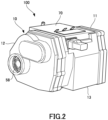
FIG. 2] FIG. 2 is an external diagram of the unit. - [
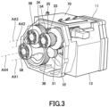
FIG. 3] FIG. 3 is an external diagram of the unit with a second cover removed. - [
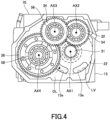
FIG. 4] FIG. 4 is a diagram of the unit with the second cover removed as viewed from a reduction mechanism side. - Hereinafter, embodiments of the present invention will be described with reference to the accompanying drawings.
-
FIG. 1 is a schematic configuration diagram of aunit 100 according to the present embodiment.FIG. 2 is an external diagram of theunit 100.FIG. 3 is an external diagram of theunit 100 with asecond cover 12 removed.FIG. 4 is a diagram of theunit 100 with thesecond cover 12 removed as viewed from areduction mechanism 30 side. InFIG. 1 , a direction perpendicular to the paper surface corresponds to a direction of gravity. In each ofFIG. 2 to FIG. 4 , an up-down direction corresponds to the direction of gravity. - Regarding the term of unit, the unit can also be referred to as, for example, a motor unit (a unit having at least a motor) or a power transmission device (a device having at least a power transmission mechanism). The motor is a rotating electric machine having an electric motor function and/or a generator function (at least one of the electric motor function and the generator function). The power transmission mechanism is, for example, a gear mechanism and/or a differential gear mechanism. A device (unit) including the motor and the power transmission mechanism is included in concepts of both the motor unit and the power transmission device.
- As shown in
FIG. 1 , theunit 100 includes ahousing 10, a rotatingelectric machine 20, areduction mechanism 30, and adifferential gear 40. Theunit 100 is mounted on a vehicle, which is an electric vehicle. Thehousing 10 includes afirst cover 11, thesecond cover 12, and acase 13. The rotatingelectric machine 20, thereduction mechanism 30, and thedifferential gear 40 are housed in thehousing 10. Thefirst cover 11 closes an opening of thecylindrical case 13 from one side in an axial direction (left side inFIG. 1 ), and thesecond cover 12 closes an opening of thecase 13 from the other side in an axial direction. The rotatingelectric machine 20 is housed in thecase 13, and thedifferential gear 40 is housed in thesecond cover 12. - As shown in
FIG. 2 to FIG. 4 , theunit 100 further includes aninverter 70. Theinverter 70 is provided on an outer wall of thecase 13. Theinverter 70 may be provided inside thecase 13. Theinverter 70 is provided close to the rotatingelectric machine 20. Theinverter 70 is provided above the rotatingelectric machine 20. The terms "above" and "below" refer to disposing that appears to overlap in the direction of gravity when viewed in a predetermined direction including the axial direction and a radial direction. For example, when a first element overlaps a second element in the direction of gravity when viewed in the axial direction, if a position of the first element is higher than that of the second element, the first element is above the second element. In this case, the first element and the second element may overlap each other or be offset when viewed in the radial direction. - The
unit 100 has oil OL. The oil OL is supplied to the rotatingelectric machine 20 in thecase 13 from the outside of thehousing 10 to lubricate the rotatingelectric machine 20, for example. A part of the oil OL supplied to the rotatingelectric machine 20 is stored in thehousing 10 and housed in thehousing 10. The remaining oil OL is discharged to the outside of thehousing 10. The oil OL can be used by being circulated inside and outside thehousing 10. - The
case 13 has throughholes 13a. The throughholes 13a are formed in thecase 13 in portions below a first axis AX1 and a fourth axis AX4 in the direction of gravity, and allow the inside of thesecond cover 12 to communicate with the inside of thecase 13. Therefore, the oil OL in thecase 13 can flow into thesecond cover 12 through the throughholes 13a, and is also used to lubricate thedifferential gear 40. An oil reservoir is formed inside each of thesecond cover 12 and thecase 13 at a portion in the lower side in the direction of gravity. In a steady circulation state, an oil level LV of the oil reservoir overlaps the throughhole 13a, for example, when viewed in the axial direction, and thus, in the steady circulation state, the oil reservoir in thesecond cover 12 and the oil reservoir in thecase 13 has a common height of an oil surface. - The steady circulation state is a state in which the oil OL is circulating steadily. For example, when oil circulation is performed using a pump, the steady circulation state is a state in which the oil level LV is stable during the pump operation. The oil circulation may be performed by a rotating member such as a gear in the
housing 10 scooping up the oil OL. In this case, the steady circulation state is a state in which the oil level LV is stable during rotation of the rotating member. - The oil level LV is set to a height at which a
stator 22 is immersed in the oil OL in the steady circulation state, and the oil OL does not enter a gap (air gap) between arotor 21 and thestator 22. This is because, when the oil OL enters the air gap, a rotation resistance of the rotatingelectric machine 20 increases rapidly, while thestator 22 is desired to be cooled. Therefore, the oil level LV is set as described above, so that the oil OL comes into contact with a coil end of thestator 22. - Returning to
FIG. 1 , the rotatingelectric machine 20 includes therotor 21, thestator 22, and arotating shaft 23, and constitutes a drive source for a vehicle. Therotor 21 is provided on the outer periphery of therotating shaft 23. Thestator 22 is provided to thecase 13 and houses therotor 21. The rotatingshaft 23 protrudes from therotor 21 toward both sides in the axial direction. The rotatingshaft 23 penetrates thefirst cover 11 at one end side in an axial direction and penetrates thecase 13 at the other end side in an axial direction. Abearing 51 is provided on thefirst cover 11 at a portion through which therotating shaft 23 penetrates, and abearing 52 is provided on thecase 13 at a portion through which therotating shaft 23 penetrates, and therotating shaft 23 is supported by thebearing 51 and thebearing 52. Aresolver 80 is provided on therotating shaft 23 at a portion protruding from thefirst cover 11. Theresolver 80 detects the rotation of the rotatingelectric machine 20. - The
reduction mechanism 30 is a gear mechanism, and includes afirst gear 31, asecond gear 32, athird gear 33, afourth gear 34, afifth gear 35, asixth gear 36, ashaft 37, and ashaft 38. Thefirst gear 31 and the rotatingelectric machine 20 are disposed on the first axis AX1. In other words, the rotatingelectric machine 20 and thefirst gear 31 are disposed coaxially with respect to the first axis AX1. In other words, a plurality of elements (components, portions, and the like) disposed on an N-th axis (N is a natural number) is synonymous with the plurality of elements disposed coaxially with respect to the N-th axis. Similarly, thesecond gear 32 and thethird gear 33 are disposed on a second axis AX2, and thefourth gear 34 and thefifth gear 35 are disposed on a third axis AX3. Thesixth gear 36 and thedifferential gear 40 are disposed on the fourth axis. - The first axis AX1, the second axis AX2, the third axis AX3, and the fourth axis AX4 all constitute axes of the
unit 100 and extend in the same direction. Therefore, the extension directions of the first axis AX1, the second axis AX2, the third axis AX3, and the fourth axis AX4 all correspond to the axial direction of theunit 100. That is, the axial direction means an axial direction of the rotating shaft of components (for example, the motor, the gear mechanism, and the differential gear mechanism) that constitute the unit. The radial direction of theunit 100 is a direction perpendicular to any of the first axis AX1, the second axis AX2, the third axis AX3, and the fourth axis AX4. The first axis AX1 constitutes an axis of therotating shaft 23, the second axis AX2 constitutes an axis of theshaft 37, the third axis AX3 constitutes an axis of theshaft 38, and a fourth axis AX4 constitutes an axis of thedifferential gear 40. - The
first gear 31 is connected downstream of the rotatingelectric machine 20. The downstream is a power output side, and therotor 21 and thestator 22 that generate power are used as references for the rotatingelectric machine 20. Therefore, the downstream of the rotatingelectric machine 20 can be said to be the downstream of thestator 22. Alternatively, the rotatingshaft 23 does not need to be understood as a component of the rotatingelectric machine 20 in terms of a positional relationship in power transmission. The downstream is the power output side, whereas the upstream is a power input side. - The
first gear 31 is connected downstream of the rotatingelectric machine 20 so as to be capable of transmitting power. The connection may be made via other configurations (for example, a clutch or other gear mechanisms). Thefirst gear 31 is provided at the other side in the axial direction of therotor 21 and is provided at therotating shaft 23 at a portion protruding from thecase 13. Thefirst gear 31 is press-fitted into the rotatingshaft 23 and is integrated with thefirst gear 31. - The
second gear 32 meshes with thefirst gear 31. Thesecond gear 32 is set to have a larger number of teeth than that of thefirst gear 31, and constitutes a first reduction gear stage together with thefirst gear 31. Thesecond gear 32 is provided at theshaft 37 and is disposed on the second axis AX2. Thesecond gear 32 is formed integrally with theshaft 37. Theshaft 37 extends along the rotatingshaft 23. Theshaft 37 is supported by abearing 53 provided at thecase 13 and abearing 54 provided at thesecond cover 12. Thebearing 53 and thebearing 54 are disposed at both ends of theshaft 37. - The
third gear 33 is connected downstream of thesecond gear 32. Thethird gear 33 is provided at theshaft 37 and disposed on the second axis AX2. Thethird gear 33 is provided at theshaft 37 at a portion extending in a direction away from the rotatingelectric machine 20 than thesecond gear 32, that is, extending on the other side in the axial direction. Thethird gear 33 is integrally formed at theshaft 37. Thesecond gear 32 and thethird gear 33 are disposed between the bearing 53 and thebearing 54 in the axial direction. - The
fourth gear 34 meshes with thethird gear 33. Thefourth gear 34 is set to have a larger number of teeth than that of thethird gear 33, and constitutes a second reduction gear stage together with thethird gear 33. Thefourth gear 34 is provided at theshaft 38 and disposed on the third axis AX3. Thefourth gear 34 is integrally formed at theshaft 38. Theshaft 38 extends along the rotatingshaft 23. Theshaft 38 is supported by abearing 55 provided at thecase 13 and abearing 56 provided at thesecond cover 12. Thebearing 55 and thebearing 56 are disposed at both ends of theshaft 38. - The
fifth gear 35 is connected downstream of thefourth gear 34. Thefifth gear 35 is provided at theshaft 38 and disposed on the third axis AX3. Thefifth gear 35 is provided at theshaft 38 at a portion extending in a direction closer to the rotatingelectric machine 20 than thefourth gear 34, that is, extending on the one side in the axial direction. Therefore, a power transmission direction of theshaft 38 is turned back to an opposite side in the axial direction as compared with theshaft 37. Thefifth gear 35 is formed integrally with theshaft 38. Thefourth gear 34 and thefifth gear 35 are disposed between the bearing 55 and thebearing 56 in the axial direction. - The
sixth gear 36 meshes with thefifth gear 35. Thesixth gear 36 is a final gear and is provided on thedifferential gear 40. Thesixth gear 36 and thedifferential gear 40 are disposed on the fourth axis AX4. The power from the rotatingelectric machine 20 is transmitted from thesixth gear 36 to thedifferential gear 40. Therefore, thedifferential gear 40 is connected downstream of thesixth gear 36. - The
sixth gear 36 overlaps thefirst gear 31 when viewed in the radial direction. In other words, thefirst gear 31 has a portion that overlaps thesixth gear 36 when viewed in the radial direction. For example, the portion overlaps thesixth gear 36 when viewed in the radial direction along a plane including the first axis AX1 and the fourth axis AX4. The expression "overlap when viewed in a predetermined direction including a radial direction and an axial direction" means overlapping in the predetermined direction, and means that a plurality of elements are disposed in the predetermined direction. Therefore, when the plurality of elements are disposed in the predetermined direction in the drawings, it may be assumed that the specification contains a sentence illustrating that a plurality of elements overlap when viewed in the predetermined direction. - In a case where the
sixth gear 36 overlaps thefirst gear 31 when viewed in the radial direction, the power transmission direction is turned back to the opposite side in the axial direction with respect to theshaft 37 by theshaft 38 as described above. Therefore, in the case where thesixth gear 36 overlaps thefirst gear 31 when viewed in the radial direction, a dimension in the axial direction is reduced. - The
sixth gear 36 is set to have a larger number of teeth than that of thefifth gear 35, and constitutes a third reduction gear stage together with thefifth gear 35. Therefore, in thereduction mechanism 30, thefirst gear 31 and thesecond gear 32, thethird gear 33 and thefourth gear 34, and thefifth gear 35 and thesixth gear 36 perform three-stage reduction. Accordingly, in order to ensure a reduction ratio, a reduction gear diameter can be made smaller than that in a case of one-stage reduction or even two-stage reduction. As a result, layout constraints such as limitations on compactness of theunit 100 due to necessity of ensuring an inter-axis distance corresponding to a large reduction gear diameter are alleviated. - That is, in the
unit 100, three gear stages can be formed by four axes, that is, the first axis AX1 to the fourth axis AX4, and the number of gear stages can be increased as compared with the case of one-stage shifting or two-stage shifting. By increasing the number of gear stages, the diameter of each gear can be made smaller to achieve a predetermined gear ratio. As a result, a factor of layout constraints caused by excessively large gears can be alleviated. Therefore, layout properties of theunit 100 can be improved. - In the
reduction mechanism 30, thethird gear 33 and thefourth gear 34 are disposed in a direction away from thestator 22 than thefirst gear 31, thesecond gear 32, thefifth gear 35, and thesixth gear 36. That is, the four gears, that is, thefirst gear 31, thesecond gear 32, thefifth gear 35, and thesixth gear 36, are moved toward thestator 22, and the remaining two gears, that is, thethird gear 33 and thefourth gear 34, are moved away from thestator 22. Accordingly, a space is formed around the above two gears, that is, on an end side of theunit 100. Therefore, an end of theunit 100 can be recessed to reduce the size, or components can be placed in the space on the end side of theunit 100, thereby increasing a freedom of layout. - The
differential gear 40 is a differential gear mechanism, and includes adifferential case 41 and adifferential portion 42. Thedifferential case 41 is supported by abearing 57 provided at thecase 13 and abearing 58 provided at thesecond cover 12, and rotates together with thesixth gear 36. Thesixth gear 36 is coaxially fixed to an outer wall of thedifferential case 41, and thedifferential case 41 houses thedifferential portion 42. Thedifferential portion 42 distributes and outputs, to drive wheels in a left-right direction of the vehicle, the power input to thedifferential case 41 via thesixth gear 36. - The
differential gear 40 protrudes in a direction away from thestator 22 with respect to thesixth gear 36. Thedifferential gear 40 protrudes in this manner with a portion that protrudes more in the axial direction from thesixth gear 36 as a protruding portion. In other words, thedifferential gear 40 protrudes more in the direction away from thestator 22 than in the direction close to thestator 22 with respect to thesixth gear 36, and is disposed in the direction away from thestator 22 with respect to thesixth gear 36. - Accordingly, the
differential gear 40 is disposed in a space on the end side of theunit 100 formed according to the gear disposing of thereduction mechanism 30. Therefore, as described above, the reduction in the dimension of thereduction mechanism 30 in the axial direction and the reduction in the gear diameter due to adoption of three-stage reduction allow theunit 100 to be made compact suitably. As a result, the layout properties of theunit 100 are further improved. - The
bearing 57 and thebearing 58 are disposed on both sides in the axial direction with respect to thedifferential gear 40. As a result, thebearing 53, thebearing 55, and thebearing 57 are disposed on the one side in the axial direction, and thebearing 54, thebearing 56, and thebearing 58 are disposed on the other side in the axial direction with respect to each gear of thereduction mechanism 30 and thedifferential gear 40. Therefore, rigidity of thehousing 10 can be ensured easily, which is advantageous in terms of sound and vibration performance. In addition, since bearing retaining holes can be machined together on the one side in the axial direction and on the other side in the axial direction, it becomes easier to align centers between the three rotating members, that is, theshaft 37, theshaft 38, and thedifferential gear 40. Furthermore, since each gear of thereduction mechanism 30 and thebearings 53 to 58 are disposed together on the other side in the axial direction with respect to thestator 22, it becomes easier to dispose theresolver 80 from the one side in the axial direction with respect to therotating shaft 23, and the rotatingelectric machine 20 can be easily assembled. - A
first drive shaft 61 is attached to thedifferential portion 42 from the one side in the axial direction, and asecond drive shaft 62 is attached to thedifferential portion 42 from the other side in the axial direction. The power from the rotatingelectric machine 20 is transmitted from thedifferential portion 42 to one drive wheel via thefirst drive shaft 61, and to the other drive wheel via thesecond drive shaft 62. Thefirst drive shaft 61 is longer than thesecond drive shaft 62, so that a distance between the drive wheel and thedifferential gear 40 is increased, thereby limiting a bending angle. Thefirst drive shaft 61 is supported by abearing 59 provided at thefirst cover 11. - The
sixth gear 36 may be understood as a part of thedifferential gear 40. That is, thesixth gear 36 may be understood as one component of thedifferential gear 40. Also in this case, it can be understood that thedifferential gear 40 including thedifferential portion 42 that outputs the power from the rotatingelectric machine 20 is connected downstream of thesixth gear 36 in such a manner that a part of thedifferential gear 40 is connected downstream of thesixth gear 36. - As shown in
FIG. 3 andFIG. 4 , the first axis AX1 and the fourth axis AX4 are disposed at a lower side of the second axis AX2 and the third axis AX3 when viewed in the axial direction. An upper side and the lower side refer to an up-down relationship in the direction of gravity when viewed in the predetermined direction including the axial direction and the radial direction, and include the "above" and "below". Regarding the "above" and "below", the upper side and the lower side further include a positional relationship of being obliquely above and below when viewed in the predetermined direction including the axial direction and the radial direction. Therefore, for example, when the first element is located obliquely above the second element without overlapping the second element in the direction of gravity when viewed in the axial direction, and the first element and the second element do not overlap when viewed in the radial direction, the first element is located at the upper side of the second element. - As a result of being disposed as described above, a layout in which the first axis AX1 and the fourth axis AX4 are disposed in a manner of being concentrated on the lower side of the
unit 100 in the direction of gravity is achieved. Accordingly, the oil OL scattered by the rotation of thesixth gear 36, which is the downstream gear, is easily guided to the rotatingelectric machine 20, resulting in a layout that allows for appropriate oil lubrication. The oil OL can be guided to the rotatingelectric machine 20 through the throughholes 13a as shown by an arrow inFIG. 4 . - Since the rotating
electric machine 20 disposed on the first axis AX1 is disposed on the lower side in the direction of gravity, it is possible to provide a space above the rotatingelectric machine 20. Therefore, it is possible to dispose theinverter 70 above the rotatingelectric machine 20 and bring theinverter 70 close to the rotatingelectric machine 20 while preventing the dimension in the radial direction from increasing. As a result, theunit 100 is more compact than that in a case where the rotatingelectric machine 20 is disposed on the upper side in the direction of gravity and theinverter 70 is further disposed above the rotatingelectric machine 20, and the layout properties of theunit 100 are improved. - Furthermore, if the rotating
electric machine 20 is disposed on the upper side in the direction of gravity, and theinverter 70, which is a high- voltage component, is disposed below the rotatingelectric machine 20, there is a concern that a leakage current due to damage may occur, but such a concern does not exist in theunit 100. A leakage current due to damage may occur, for example, when theinverter 70 is crushed by a heavy object including the rotatingelectric machine 20 during a vehicle collision, or when an impact load is applied to theinverter 70 when the bottom of the vehicle is hit. - In the
unit 100, the gear diameter is reduced by adopting the three-stage reduction as described above, and as a result, the layout restrictions are alleviated. Therefore, a relative height of an oil surface of the oil reservoir for each of the rotatingelectric machine 20 and thedifferential gear 40 can be easily set appropriately by respectively disposing the rotatingelectric machine 20 and thedifferential gear 40. - In this case, the height of the oil surface can be set more appropriately for the
differential gear 40 by relatively raising the height of the oil surface of the oil reservoir in the second cover 12 (thus lowering a position of the differential gear 40). In addition, the height of the oil surface can be set more appropriately for the rotatingelectric machine 20 by relatively lowering the height of the oil surface of the oil reservoir in the case 13 (thus raising a position of the rotating electric machine 20) in order to prevent the oil OL from penetrating the air gap between therotor 21 and thestator 22. From this perspective, in theunit 100, the first axis AX1 is disposed at an upper side of the fourth axis AX4. - Next, main functions and effects of the present embodiment will be described.
- (1) The
unit 100 includes thehousing 10 that houses the oil OL, the rotatingelectric machine 20, thefirst gear 31 connected downstream of the rotatingelectric machine 20, thesecond gear 32 meshing with thefirst gear 31, thethird gear 33 connected downstream of thesecond gear 32, thefourth gear 34 meshing with thethird gear 33, thefifth gear 35 connected downstream of thefourth gear 34, and thesixth gear 36 meshing with thefifth gear 35. The rotatingelectric machine 20 and thefirst gear 31 are disposed on the first axis AX1. Thesecond gear 32 and thethird gear 33 are disposed on the second axis AX2. Thefourth gear 34 and thefifth gear 35 are disposed on the third axis AX3. Thesixth gear 36 is disposed on the fourth axis AX4. When viewed in the axial direction, the first axis AX1 and the fourth axis AX4 are disposed in the lower side of the second axis AX2 and the third axis AX3. - According to such a configuration, by increasing the number of gear stages, a diameter of each gear can be made smaller to achieve a predetermined gear ratio. As a result, a factor of layout constraints caused by excessively large gears can be alleviated. Therefore, layout properties of the
unit 100 can be improved. In addition, by concentrating the first axis AX1 and the fourth axis AX4 on the lower side in the direction of gravity, it becomes easier to guide the oil OL scattered by rotation of thesixth gear 36, which is a gear on the downstream side, to the rotatingelectric machine 20 as described above. Therefore, a layout that allows for appropriate oil lubrication is achieved. - In this case, the layout properties of the
unit 100 can also be improved by making theunit 100 compact as described above. Also in this case, there is no concern of a leakage current due to damage to theinverter 70 as described above, and the relative height of the oil surface of the oil reservoir for each of the rotatingelectric machine 20 and thedifferential gear 40 can be easily set appropriately. - (2) In the
unit 100, thefirst gear 31 has a portion overlapping thesixth gear 36 when viewed in the radial direction. According to such a configuration, the dimension in the axial direction can be shortened as compared with that in a case where thedifferential gear 40 is disposed in an inverted manner in the axial direction with respect to thethird gear 33 and thefourth gear 34, which contributes to shortening the dimension in the axial direction. - (3) In the
unit 100, thethird gear 33 and thefourth gear 34 are disposed in the direction away from thestator 22 than thefirst gear 31, thesecond gear 32, thefifth gear 35, and thesixth gear 36. Accordingly, a space is formed around thethird gear 33 and thefourth gear 34, that is, on the end side of theunit 100. Therefore, the end side of theunit 100 can be recessed to reduce the size, or other components can be placed in the space on the end side of theunit 100, thereby increasing a freedom of layout. - (4) The
unit 100 includes thedifferential gear 40 connected downstream of thesixth gear 36. Thedifferential gear 40 is disposed on the fourth axis AX4. Thedifferential gear 40 protrudes in the direction away from thestator 22 with respect to thesixth gear 36. According to such a configuration, thedifferential gear 40 is disposed in the space on the end side of theunit 100, and thus theunit 100 can be suitably made compact, and the degree of freedom in layout can be further increased. - Although the embodiment of the present invention has been described above, the above embodiment merely exemplifies some of application examples of the present invention and does not intend to limit the technical scope of the present invention to the specific configurations of the above embodiment.
-
- 10
- housing
- 20
- rotating electric machine
- 21
- rotor
- 22
- stator
- 23
- rotating shaft
- 30
- reduction mechanism
- 31
- first gear
- 32
- second gear
- 33
- third gear
- 34
- fourth gear
- 35
- fifth gear
- 36
- sixth gear
- 40
- differential gear
- 70
- inverter
- 100
- unit
- AX1
- first axis
- AX2
- second axis
- AX3
- third axis
- AX4
- fourth axis
Claims (4)
- A unit, comprising:a housing configured to house oil, a rotating electric machine, a first gear connected downstream of the rotating electric machine, a second gear meshing with the first gear, a third gear connected downstream of the second gear, a fourth gear meshing with the third gear, a fifth gear connected downstream of the fourth gear, and a sixth gear meshing with the fifth gear, whereinthe rotating electric machine and the first gear are disposed on a first axis,the second gear and the third gear are disposed on a second axis,the fourth gear and the fifth gear are disposed on a third axis,the sixth gear is disposed on a fourth axis, andwhen viewed in an axial direction, the first axis and the fourth axis are disposed at a lower side of the second axis and the third axis.
- The unit according to claim 1, wherein
when viewed in a radial direction, the first gear has a portion that overlaps the sixth gear. - The unit according to claim 1 or 2, wherein
the third gear and the fourth gear are disposed in a direction away from a stator of the rotating electric machine than the first gear, the second gear, the fifth gear, and the sixth gear. - The unit according to claim 3, further comprising:a differential gear connected downstream of the sixth gear, whereinthe differential gear is disposed on the fourth axis, andthe differential gear protrudes in the direction away from the stator with respect to the sixth gear.
Applications Claiming Priority (2)
| Application Number | Priority Date | Filing Date | Title |
|---|---|---|---|
| JP2022095081 | 2022-06-13 | ||
| PCT/JP2023/017854 WO2023243277A1 (en) | 2022-06-13 | 2023-05-12 | Unit |
Publications (2)
| Publication Number | Publication Date |
|---|---|
| EP4538559A1 true EP4538559A1 (en) | 2025-04-16 |
| EP4538559A4 EP4538559A4 (en) | 2025-09-24 |
Family
ID=89191140
Family Applications (1)
| Application Number | Title | Priority Date | Filing Date |
|---|---|---|---|
| EP23821877.0A Pending EP4538559A4 (en) | 2022-06-13 | 2023-05-12 | UNIT |
Country Status (5)
| Country | Link |
|---|---|
| US (1) | US20250361933A1 (en) |
| EP (1) | EP4538559A4 (en) |
| JP (1) | JP7676667B2 (en) |
| CN (1) | CN119343548A (en) |
| WO (1) | WO2023243277A1 (en) |
Families Citing this family (1)
| Publication number | Priority date | Publication date | Assignee | Title |
|---|---|---|---|---|
| CN118438834B (en) * | 2024-07-08 | 2024-10-11 | 比亚迪股份有限公司 | Drive axle assembly and vehicle |
Family Cites Families (25)
| Publication number | Priority date | Publication date | Assignee | Title |
|---|---|---|---|---|
| JP4074278B2 (en) * | 2004-09-09 | 2008-04-09 | ジヤトコ株式会社 | Baffle plate oil drain structure |
| DE102006045240A1 (en) * | 2006-09-26 | 2008-04-03 | Zf Friedrichshafen Ag | A method of level control of an oil sump portion of an oil sump having at least two oil sump portions |
| US8931596B2 (en) * | 2010-02-04 | 2015-01-13 | Toyota Jidosha Kabushiki Kaisha | Lubricant oil supplying apparatus |
| JP2012189178A (en) | 2011-03-11 | 2012-10-04 | Showa Corp | Reduction gear and differential device with motor |
| JP6819083B2 (en) * | 2016-06-13 | 2021-01-27 | 三菱自動車工業株式会社 | Transaxle device |
| KR101916075B1 (en) * | 2016-12-09 | 2018-11-07 | 현대자동차 주식회사 | Oil circulation system of transmission case |
| JP6923466B2 (en) * | 2018-02-09 | 2021-08-18 | トヨタ自動車株式会社 | Vehicle drive |
| DE102018009582A1 (en) | 2018-12-05 | 2020-06-10 | Daimler Ag | Electric axle drive for a commercial vehicle |
| JP6973965B2 (en) * | 2019-02-08 | 2021-12-01 | ジヤトコ株式会社 | Power transmission device |
| CN113454364A (en) * | 2019-02-08 | 2021-09-28 | 加特可株式会社 | Power transmission device |
| EP3940264B1 (en) * | 2019-03-10 | 2024-07-17 | Jatco Ltd. | Power transmission device |
| WO2020194960A1 (en) * | 2019-03-27 | 2020-10-01 | アイシン・エィ・ダブリュ株式会社 | Vehicle drive device |
| EP3798076A1 (en) * | 2019-09-27 | 2021-03-31 | Traktionssysteme Austria GmbH | Gearbox |
| CN114655024B (en) | 2019-12-26 | 2024-03-22 | 株式会社爱信 | Driving device for vehicle |
| JP7639709B2 (en) * | 2020-01-10 | 2025-03-05 | ニデック株式会社 | Motor Unit |
| US11448305B2 (en) * | 2020-11-24 | 2022-09-20 | Dana Automotive Systems Group, Llc | Vehicle product line with multiple gear train assemblies |
| EP4310366B1 (en) * | 2021-03-19 | 2025-05-21 | Jatco Ltd. | Power transmission device |
| US12508898B2 (en) * | 2021-03-30 | 2025-12-30 | Aisin Corporation | Vehicle drive device |
| EP4360938B1 (en) * | 2021-06-24 | 2025-11-12 | Jatco Ltd | Unit |
| EP4362296A4 (en) * | 2021-06-26 | 2024-11-13 | JATCO Ltd | UNIT |
| US12206316B2 (en) * | 2021-06-26 | 2025-01-21 | Jatco Ltd | Unit |
| JP7501485B2 (en) * | 2021-09-28 | 2024-06-18 | 株式会社アイシン | Vehicle drive device |
| JP7547025B2 (en) * | 2022-03-10 | 2024-09-09 | ジヤトコ株式会社 | Device |
| CN119318103A (en) * | 2022-06-07 | 2025-01-14 | 加特可株式会社 | unit |
| US20250368020A1 (en) * | 2022-06-14 | 2025-12-04 | Jatco Ltd | Vehicle and vehicle manufacturing method |
-
2023
- 2023-05-12 EP EP23821877.0A patent/EP4538559A4/en active Pending
- 2023-05-12 CN CN202380046323.1A patent/CN119343548A/en active Pending
- 2023-05-12 JP JP2024528385A patent/JP7676667B2/en active Active
- 2023-05-12 WO PCT/JP2023/017854 patent/WO2023243277A1/en not_active Ceased
- 2023-05-12 US US18/873,587 patent/US20250361933A1/en active Pending
Also Published As
| Publication number | Publication date |
|---|---|
| JPWO2023243277A1 (en) | 2023-12-21 |
| CN119343548A (en) | 2025-01-21 |
| JP7676667B2 (en) | 2025-05-14 |
| WO2023243277A1 (en) | 2023-12-21 |
| EP4538559A4 (en) | 2025-09-24 |
| US20250361933A1 (en) | 2025-11-27 |
Similar Documents
| Publication | Publication Date | Title |
|---|---|---|
| JP7501506B2 (en) | Vehicle drive device | |
| JP2021008901A (en) | Driving device | |
| JP4337800B2 (en) | Power transmission device for hybrid vehicle | |
| CN111649117A (en) | Motor drive device for vehicle | |
| EP4538559A1 (en) | Unit | |
| EP4661258A1 (en) | Unit | |
| US20210320544A1 (en) | Cooling device for on-vehicle rotating electrical machine | |
| EP4661259A1 (en) | Unit | |
| EP4539309A1 (en) | Unit | |
| JP4207542B2 (en) | Electric wheel drive device | |
| US12338880B2 (en) | Vehicle drive device | |
| JP2025051109A (en) | Electric vehicle driving device | |
| EP4539308A1 (en) | Unit | |
| WO2023243275A1 (en) | Unit | |
| US20140302958A1 (en) | Drive device having an electrical drive machine | |
| JP2023008916A (en) | Vehicle drive system | |
| EP4604360A1 (en) | Unit | |
| WO2024135164A1 (en) | Unit | |
| CN113677555A (en) | Electric drives for vehicles | |
| JP7647926B2 (en) | Vehicle drive device | |
| KR102781380B1 (en) | Electric axle apparatus | |
| EP4611235A1 (en) | Vehicle drive system | |
| WO2024135165A1 (en) | Unit | |
| EP4538088A1 (en) | Unit | |
| CN121358976A (en) | Components |
Legal Events
| Date | Code | Title | Description |
|---|---|---|---|
| STAA | Information on the status of an ep patent application or granted ep patent |
Free format text: STATUS: THE INTERNATIONAL PUBLICATION HAS BEEN MADE |
|
| PUAI | Public reference made under article 153(3) epc to a published international application that has entered the european phase |
Free format text: ORIGINAL CODE: 0009012 |
|
| STAA | Information on the status of an ep patent application or granted ep patent |
Free format text: STATUS: REQUEST FOR EXAMINATION WAS MADE |
|
| 17P | Request for examination filed |
Effective date: 20241122 |
|
| AK | Designated contracting states |
Kind code of ref document: A1 Designated state(s): AL AT BE BG CH CY CZ DE DK EE ES FI FR GB GR HR HU IE IS IT LI LT LU LV MC ME MK MT NL NO PL PT RO RS SE SI SK SM TR |
|
| REG | Reference to a national code |
Ref country code: DE Ref legal event code: R079 Free format text: PREVIOUS MAIN CLASS: F16H0001060000 Ipc: F16H0057040000 |
|
| DAV | Request for validation of the european patent (deleted) | ||
| DAX | Request for extension of the european patent (deleted) | ||
| A4 | Supplementary search report drawn up and despatched |
Effective date: 20250822 |
|
| RIC1 | Information provided on ipc code assigned before grant |
Ipc: F16H 57/04 20100101AFI20250818BHEP Ipc: H02K 7/116 20060101ALI20250818BHEP Ipc: B60K 1/00 20060101ALI20250818BHEP Ipc: F16H 57/021 20120101ALI20250818BHEP Ipc: F16H 57/031 20120101ALI20250818BHEP Ipc: F16H 1/20 20060101ALN20250818BHEP |