EP4538467A1 - Improved hydraulic arrangement for a work machine, work machine provided with such hydraulic arrangement and combination of such work machine and a coupling device - Google Patents
Improved hydraulic arrangement for a work machine, work machine provided with such hydraulic arrangement and combination of such work machine and a coupling device Download PDFInfo
- Publication number
- EP4538467A1 EP4538467A1 EP24205943.4A EP24205943A EP4538467A1 EP 4538467 A1 EP4538467 A1 EP 4538467A1 EP 24205943 A EP24205943 A EP 24205943A EP 4538467 A1 EP4538467 A1 EP 4538467A1
- Authority
- EP
- European Patent Office
- Prior art keywords
- hydraulic
- port
- valve
- line
- coupling member
- Prior art date
- Legal status (The legal status is an assumption and is not a legal conclusion. Google has not performed a legal analysis and makes no representation as to the accuracy of the status listed.)
- Pending
Links
Images

Classifications
-
- E—FIXED CONSTRUCTIONS
- E02—HYDRAULIC ENGINEERING; FOUNDATIONS; SOIL SHIFTING
- E02F—DREDGING; SOIL-SHIFTING
- E02F3/00—Dredgers; Soil-shifting machines
- E02F3/04—Dredgers; Soil-shifting machines mechanically-driven
- E02F3/28—Dredgers; Soil-shifting machines mechanically-driven with digging tools mounted on a dipper- or bucket-arm, i.e. there is either one arm or a pair of arms, e.g. dippers, buckets
- E02F3/36—Component parts
- E02F3/3604—Devices to connect tools to arms, booms or the like
- E02F3/3609—Devices to connect tools to arms, booms or the like of the quick acting type, e.g. controlled from the operator seat
- E02F3/3663—Devices to connect tools to arms, booms or the like of the quick acting type, e.g. controlled from the operator seat hydraulically-operated
-
- E—FIXED CONSTRUCTIONS
- E02—HYDRAULIC ENGINEERING; FOUNDATIONS; SOIL SHIFTING
- E02F—DREDGING; SOIL-SHIFTING
- E02F3/00—Dredgers; Soil-shifting machines
- E02F3/04—Dredgers; Soil-shifting machines mechanically-driven
- E02F3/28—Dredgers; Soil-shifting machines mechanically-driven with digging tools mounted on a dipper- or bucket-arm, i.e. there is either one arm or a pair of arms, e.g. dippers, buckets
- E02F3/36—Component parts
- E02F3/3604—Devices to connect tools to arms, booms or the like
- E02F3/3609—Devices to connect tools to arms, booms or the like of the quick acting type, e.g. controlled from the operator seat
- E02F3/3618—Devices to connect tools to arms, booms or the like of the quick acting type, e.g. controlled from the operator seat with two separating hooks
-
- E—FIXED CONSTRUCTIONS
- E02—HYDRAULIC ENGINEERING; FOUNDATIONS; SOIL SHIFTING
- E02F—DREDGING; SOIL-SHIFTING
- E02F9/00—Component parts of dredgers or soil-shifting machines, not restricted to one of the kinds covered by groups E02F3/00 - E02F7/00
- E02F9/20—Drives; Control devices
- E02F9/22—Hydraulic or pneumatic drives
- E02F9/2221—Control of flow rate; Load sensing arrangements
- E02F9/2225—Control of flow rate; Load sensing arrangements using pressure-compensating valves
- E02F9/2228—Control of flow rate; Load sensing arrangements using pressure-compensating valves including an electronic controller
-
- F—MECHANICAL ENGINEERING; LIGHTING; HEATING; WEAPONS; BLASTING
- F15—FLUID-PRESSURE ACTUATORS; HYDRAULICS OR PNEUMATICS IN GENERAL
- F15B—SYSTEMS ACTING BY MEANS OF FLUIDS IN GENERAL; FLUID-PRESSURE ACTUATORS, e.g. SERVOMOTORS; DETAILS OF FLUID-PRESSURE SYSTEMS, NOT OTHERWISE PROVIDED FOR
- F15B2211/00—Circuits for servomotor systems
- F15B2211/30—Directional control
- F15B2211/305—Directional control characterised by the type of valves
- F15B2211/30505—Non-return valves, i.e. check valves
- F15B2211/3051—Cross-check valves
-
- F—MECHANICAL ENGINEERING; LIGHTING; HEATING; WEAPONS; BLASTING
- F15—FLUID-PRESSURE ACTUATORS; HYDRAULICS OR PNEUMATICS IN GENERAL
- F15B—SYSTEMS ACTING BY MEANS OF FLUIDS IN GENERAL; FLUID-PRESSURE ACTUATORS, e.g. SERVOMOTORS; DETAILS OF FLUID-PRESSURE SYSTEMS, NOT OTHERWISE PROVIDED FOR
- F15B2211/00—Circuits for servomotor systems
- F15B2211/30—Directional control
- F15B2211/305—Directional control characterised by the type of valves
- F15B2211/30525—Directional control valves, e.g. 4/3-directional control valve
-
- F—MECHANICAL ENGINEERING; LIGHTING; HEATING; WEAPONS; BLASTING
- F15—FLUID-PRESSURE ACTUATORS; HYDRAULICS OR PNEUMATICS IN GENERAL
- F15B—SYSTEMS ACTING BY MEANS OF FLUIDS IN GENERAL; FLUID-PRESSURE ACTUATORS, e.g. SERVOMOTORS; DETAILS OF FLUID-PRESSURE SYSTEMS, NOT OTHERWISE PROVIDED FOR
- F15B2211/00—Circuits for servomotor systems
- F15B2211/30—Directional control
- F15B2211/31—Directional control characterised by the positions of the valve element
- F15B2211/3105—Neutral or centre positions
- F15B2211/3111—Neutral or centre positions the pump port being closed in the centre position, e.g. so-called closed centre
-
- F—MECHANICAL ENGINEERING; LIGHTING; HEATING; WEAPONS; BLASTING
- F15—FLUID-PRESSURE ACTUATORS; HYDRAULICS OR PNEUMATICS IN GENERAL
- F15B—SYSTEMS ACTING BY MEANS OF FLUIDS IN GENERAL; FLUID-PRESSURE ACTUATORS, e.g. SERVOMOTORS; DETAILS OF FLUID-PRESSURE SYSTEMS, NOT OTHERWISE PROVIDED FOR
- F15B2211/00—Circuits for servomotor systems
- F15B2211/30—Directional control
- F15B2211/31—Directional control characterised by the positions of the valve element
- F15B2211/3122—Special positions other than the pump port being connected to working ports or the working ports being connected to the return line
- F15B2211/3127—Floating position connecting the working ports and the return line
-
- F—MECHANICAL ENGINEERING; LIGHTING; HEATING; WEAPONS; BLASTING
- F15—FLUID-PRESSURE ACTUATORS; HYDRAULICS OR PNEUMATICS IN GENERAL
- F15B—SYSTEMS ACTING BY MEANS OF FLUIDS IN GENERAL; FLUID-PRESSURE ACTUATORS, e.g. SERVOMOTORS; DETAILS OF FLUID-PRESSURE SYSTEMS, NOT OTHERWISE PROVIDED FOR
- F15B2211/00—Circuits for servomotor systems
- F15B2211/70—Output members, e.g. hydraulic motors or cylinders or control therefor
- F15B2211/705—Output members, e.g. hydraulic motors or cylinders or control therefor characterised by the type of output members or actuators
- F15B2211/7051—Linear output members
- F15B2211/7053—Double-acting output members
Definitions
- the present invention relates to an improved hydraulic arrangement for a work machine, in particular for an earth-moving machine such as an excavator, a digger, a mechanical shovel or the like.
- the present invention further relates to a work machine provided with such hydraulic arrangement, to a combination of such work machine and a coupling device and to a related control method.
- the present invention finds its preferred, although not exclusive, application in a hydraulic arrangement for controlling a quick coupler adapted to be carried by a hydraulically actuated arm, of an excavator or the like. Reference will be made to this application by way of example below, without however losing in generality.
- work machines such as excavators, diggers and the like are provided with a hydraulically actuated work implement, which is carried by a body of the work machine and is configured to perform multiple earth-moving operations, such as digging, handling earth or gravel, loading trucks and/or similar operations.
- Such hydraulically actuated work implement comprises: a boom rotatably carried by the body of the work machine; a boom actuator configured to rotate the boom with respect to the body of the work machine; a stick or arm or dipper rotatably carried by the boom; an arm hydraulic actuator configured to rotate the arm with respect to the boom; a work tool, such as a bucket or the like, rotatably carried by the arm; and a bucket hydraulic actuator configured to rotate the bucket with respect to the arm.
- a plurality of different types of work tools may be carried by the arm, depending on the specific operation to be carried out by the work machine, such as buckets, rakes, grapples, asphalt cutters or the like.
- Hydraulically actuated quick couplers have been developed to allow such work tools to be quickly exchanged without the need for manual intervention by an operator or, for instance, without the driver of the working machine having to get out of the cab.
- Such hydraulically actuated quick couplers are adapted to be rotatably carried by the free end of the arm of the work machine and are configured to allow the rapid exchange of buckets or similar tools.
- FIG. 1 A schematic example of such hydraulically actuated quick couplers is represented in Figure 1 and is denoted as a whole with reference number 100.
- quick coupler 100 comprises a first coupling interface 110, which is configured to be mechanically connected to the free end of the arm of the hydraulic machine.
- quick coupler 100 comprises a second coupling interface 120 adapted to be selectively connected to the work tool to be attached to the arm of the work machine.
- second hydraulically actuated coupling interface 120 comprises a hydraulically actuated coupling member 130, such as one or more hook, which is carried in a movable manner by the body of the same quick coupler 100 and is selectively operable between an unlocking position and a locking position, in order to lock and unlock the attached work tool.
- a hydraulically actuated coupling member 130 such as one or more hook
- quick coupler 100 comprises a double effect hydraulic cylinder 140 configured to arrange the coupling member 130 in the locked and in the unlocked position.
- a first chamber of the hydraulic cylinder 140 is fluidly connected to a source of pressurized hydraulic fluid, while the second chamber of the same hydraulic cylinder 140 is connected to tank.
- hydraulic cylinder 140 is hydraulically connected to a hydraulic circuit 150 of the work machine via a pair of flexible hoses 160a and 160b, which are routed along the hydraulically actuated work implement, i.e. along the boom and the arm of the same work machine.
- the two flexible hoses 160a and 160b are connected to hydraulic ports arranged on the body of the quick coupler 100, which in turn are fluidly connected to the two chambers of the hydraulic cylinder 140.
- hydraulic circuit 150 comprises a valve arrangement 170 configured to selectively pressurize the first chamber of such hydraulic cylinder 140, in order to arrange the coupling member of quick coupler in the locking position.
- Patent application US20230160172 A1 discloses a similar quick coupler, denoted with number 400.
- quick coupler 400 disclosed in US20230160172 A1 comprises a hydraulic cylinder 420, which is operatively connected to blocking members 430 and 440 and is configured to selectively arrange such blocking members 430 and 440 in a locking position or in an unlocking position.
- blocking members 430 and 440 are configured to prevent a work tool 500 to separate from quick coupler 400 and an unlocking position.
- blocking members 430 and 440 are configured to allow detachment of work tool 500 from quick coupler 400.
- US20230160172 A1 discloses a hydraulic assembly 600 fluidly connected to hydraulic cylinder 420 and configured to control operation of the latter.
- hydraulic assembly 600 comprises a pump 601, a tank 602 and a directional assembly 610, in particular a directional control valve 610a, fluidly interposed between hydraulic cylinder 420, pump 601 and tank 602.
- directional control valve 610a is configured to be selectively and alternatively arranged in a first position, in which it arranges the hydraulic cylinder 420 in the locking position, in a second position, in which it arranges the hydraulic cylinder 420 in the unlocking position, and in a third floating position in which it fluidly connects both chambers of hydraulic cylinder 420 with tank 602.
- quick couplers of different manufacturers have different hydraulic interfaces, and sometimes the position of the two hydraulic ports configured to be hydraulic connected to the two flexible hoses 160a and 160b on the quick coupler 100 may be reversed with respect to the position of the respective flexible hose 160a or 160b.
- Aim of the present invention is to satisfy the above-mentioned need in an optimized and cost-effective manner.
- number 1 denotes, as a whole, a work machine, in particular an earth-moving machine such as an excavator, a digger, a mechanical shovel or the like.
- Work machine 1 comprises a body movable on the ground via ground engaging wheels or tracks.
- said body preferably comprises: a lower frame or undercarriage, which carries the ground engaging wheels or tracks to allow motion of the body with respect to the ground; and an upper frame or superstructure, which is carried in a rotatable manner by lower frame preferably about a rotation axis orthogonal to the advancing plane of work machine 1, i.e. orthogonal to the ground.
- work machine 1 comprises a hydraulically actuated work implement or work arm, which is carried by the body and is configured to perform multiple earth moving operations, such as digging, handling earth or gravel, loading trucks and/or similar operations.
- said work implement is rotatably carried by the upper frame of work machine 1.
- the hydraulically actuated work implement preferably comprises: a boom rotatably carried by the body; and a stick or arm or dipper, which is rotatably carried by the boom and, in turn, is configured to carry in a rotatable manner a work tool, such as buckets, rakes, grapples, asphalt cutters or the like.
- work machine 1 preferably comprises a plurality of hydraulic cylinders, in particular double-acting hydraulic cylinders, configured to actuate the hydraulically actuated work implement.
- work machine 1 comprises at least one boom actuator, which is operatively interposed between the work machine body and the boom and is configured to rotate the boom with respect to said body.
- work machine 1 further comprises at least one arm actuator, which is operatively interposed between the boom and the arm and is configured to rotate the arm with respect to the boom.
- work machine 1 further comprises also at least one bucket actuator, which is operatively interposed between the arm and the work tool and is configured to rotate the same work tool with respect to the arm.
- bucket actuator which is operatively interposed between the arm and the work tool and is configured to rotate the same work tool with respect to the arm.
- number 200 indicates as a whole a coupling device, in the following referred to also as “quick coupler” or “quick hitch”, which is configured to be rotatably carried by the work implement, in particular by the arm of work machine 1, and is further configured to allow the connection of the work tool to the same arm.
- quick coupler or “quick hitch”
- quick coupler 200 is configured to allow rapid exchange between different work tools without the need for manual intervention by an operator.
- quick coupler 200 is configured to be interposed between the arm of work vehicle 1 and the bucket or other similar work tools.
- quick coupler 200 comprises a first coupling interface 220 configured to be rotatably carried by the free end of the arm of work vehicle 1 opposite to the boom.
- first coupling interface 220 is preferably configured to be mechanically connected to the free end of the arm of work machine 1.
- first coupling interface 220 may comprise a pair of holes 230, which are realized on the body 210 of the quick coupler 200 and are configured to be engaged by respective pins carried by the arm of work machine 1, to securely attach the quick coupler 200 to the same arm.
- quick coupler 200 comprises a second coupling interface 240, which is adapted to be mechanically connected to the work tools to be attached to the arm of work machine 1.
- the second coupling interface 240 comprises a hydraulically actuated coupling member 250, which is configured to be coupled to the work tool and is selectively arrangeable in a locking position, in which it is configured to firmly/securely attach the work tool to the same quick coupler 200, and an unlocking position, in which it allows detachment of the work tool from quick coupler 200 and work machine 1.
- the coupling member 250 preferably comprises two hooks 250, which are adapted to engage respective pins carried by the work tool, in order to securely attach the same work tool to the arm of work machine 1.
- one of the two hooks 250 is fixedly/rigidly carried by the body 210 and the other one between the two hooks 260 is carried in a movable manner and is movable from and towards a locking position, in which it is configured to engage a respective pin of the work tool, in order to firmly attach the same work tool to the quick coupler 200.
- coupling member 250 is arranged in the locking position, while by pressurizing the other hydraulic port 270b of hydraulic actuator 270, coupling member 250 is arranged in the unlocking position.
- the hydraulic port of the hydraulic actuator 270 to be pressurized to arrange the coupling member 250 in the locking position may vary, for instance on the manufacturer and/or the model of the quick coupler 200.
- the hydraulic actuator 270 comprises a double-effect hydraulic cylinder 280.
- one chamber of hydraulic cylinder 280 is configured to be connected to a source of pressurized hydraulic fluid and the other chamber of hydraulic cylinder 280 is configured to be connected to a tank, a reservoir or the like, in order selectively operate the hydraulically actuated coupling member 250 in the locking or in the unlocking position.
- quick coupler 200 preferably comprises a first hydraulic port 290a and a second hydraulic port 290b, which are realized on the body 210 of the same quick coupler 200, are fluidly connected respectively to port 270a and to port 270b of the hydraulic actuator 270, and are configured to be fluidly connected, on command, to a source of pressurized fluid and to a tank of work machine 1, for instance by means of flexible hoses, to allow fluidly connecting the two chambers of the hydraulic actuator 270 to the source of pressurized of hydraulic fluid and to tank.
- the two hydraulic ports 290a and 290b are spaced apart to each other on opposite sides of the vertical midplane of the same quick coupler 200.
- a first between hydraulic ports 290a and 290b is configured to receive pressurized hydraulic fluid in order to control hydraulic cylinder 270 to arrange coupling member 250 in the locking position.
- the second one between hydraulic ports 290a and 290b is configured to receive pressurized hydraulic fluid in order to control hydraulic cylinder 270 to arrange coupling member 250 in the unlocking position.
- the hydraulic port to be pressurized in order to arrange coupling member 250 in the looking or unlocking position may change.
- work vehicle 1 further comprises a hydraulic arrangement 4, which is configured to be hydraulically connected to the quick coupler 200, in particular to the hydraulic actuator 270 via hydraulic ports 290a and 290b, and is configured to operate the same hydraulic actuator 270.
- hydraulic arrangement 4 comprises a source of pressurized hydraulic fluid 6.
- Source of pressurized hydraulic fluid 6 in particular, is configured to provide at outlet a pressurized flow of hydraulic fluid.
- source of pressurized hydraulic fluid 6 comprises a hydraulic pump, which is carried by an engine of work machine 1 and is adapted to be driven in rotation in order to suck hydraulic fluid from a tank 7 and to provide at outlet a pressurized flow of such hydraulic fluid.
- a hydraulic pump which is carried by an engine of work machine 1 and is adapted to be driven in rotation in order to suck hydraulic fluid from a tank 7 and to provide at outlet a pressurized flow of such hydraulic fluid.
- hydraulic arrangement 4 further comprises a hydraulic circuit 10, which is configured to be fluidly connected to the quick coupler 200 in order to put the hydraulic actuator 270 in fluid communication with the source of pressurized hydraulic fluid 6 and with a tank 7.
- hydraulic circuit 10 is preferably configured to be fluidly connected to ports 290a and 290b of quick coupler 200.
- hydraulic circuit 10 comprises a second hydraulic line 14, in the following referred to as "low pressure hydraulic line", which is configured to fluidly connect the quick coupler 200, in particular the hydraulic actuator 270 with tank 7.
- hydraulic circuit 10 further comprises a valve assembly 16, which is adapted to be fluidly interposed between the high-pressure line, the low-pressure line and the hydraulic actuator 270 of quick coupler 200 and is configured to control the flow of pressurized hydraulic fluid provided to the same hydraulic actuator 270.
- valve assembly 16 is preferably configured to be fluidly connected to the first port 290a and to the second port 290b of quick coupler 200, via a first hydraulic line 18 and via a second hydraulic line 20.
- valve assembly 16 is configured to selectively fluidly connect, on command, a first one between first hydraulic port 290a and a second hydraulic port 290b with first hydraulic line 12, and a second one between first hydraulic port 290a and a second hydraulic port 290b with second hydraulic line 14.
- First hydraulic line 18 and second hydraulic line 20 preferably comprise each a flexible hose 19 and 21 configured to connect the hydraulic arrangement 4 carried by work machine 1 body with the quick coupler 200 carried by the hydraulically actuated work implement, in particular by the arm.
- Flexible hoses 19 and 21 are preferably routed along the boom and the arm and they preferably extend one aside, in particular substantially parallel, to the other.
- flexible hoses 19 and 21 are preferably arranged one spaced aside the other on opposite sides of the vertical midplane of the hydraulically actuated arm of work vehicle 1.
- flexible hose 19 is adapted to be fluidly connected to port 290b
- flexible hose 21 is adapted to be fluidly connected to port 290a, in order to avoid crossing of flexible hoses 19 and 21.
- line 18 preferably connects valve assembly 16 with port 290b of quick coupler 200
- line 20 preferably connects valve assembly 16 with port 290a of quick coupler 200.
- a first port 22a of valve 22 is preferably fluidly connected to the high-pressure line 12 and to source 6 and a second port 22b of valve 22 is preferably fluidly connected to low-pressure line 14 and to tank 7.
- the two other ports 22c and 22d of valve 22 are configured to be fluidly connected to the hydraulic actuator 270.
- valve 22 are preferably configured to be fluidly connected to hydraulic ports 290 of quick coupler 200 via line 18 and line 20 respectively.
- valve 22 is preferably configured to put the two ports 270a and 270b of hydraulic actuator 270 in fluid communication with low-pressure line 14 and to fluidly isolate high-pressure line 12.
- valve 22 is preferably configured to put the two ports 290a and 290b of hydraulic coupler and the two lines 18 and 20 in fluid communication with low-pressure line 14 and to fluidly isolate high-pressure line 12.
- valve 22 comprises biasing means 23 configured to bias valve 22 in the first position.
- valve 22 is preferably configured to put port 270a of hydraulic actuator 270, in particular port 290a, in fluid communication with high-pressure line 12 and port 270b of hydraulic actuator 27, in particular port 290b, in fluid communication with low-pressure line 14.
- valve 22 is preferably configured to put port 270a of hydraulic actuator 270, in particular port 290a, in fluid communication with low-pressure line 14 and port 270b of hydraulic actuator 27, in particular port 290b, in fluid communication with high-pressure line 12.
- valve 22 in the second position, is preferably configured to put port 290a and line 20 in fluid communication with high-pressure line 12 and a port 290b and line 18 in fluid communication with low-pressure line 14.
- valve 22 is preferably configured to put port 290b and line 18 in fluid communication with high-pressure line 12 and a port 290a and line 20 in fluid communication with low-pressure line 14.
- valve assembly 16 further comprises two solenoids 26, which are operable to selectively arrange valve 22 in the second or in the third position.
- hydraulic arrangement 4 preferably comprises two check valves 28 and 30, which are respectively arranged along line 18 and 20, advantageously downstream valve assembly 16.
- Check valve 28 and 30 are preferably configured to allow unidirectional flow of the pressurized hydraulic fluid from the source 6 and valve assembly 22 towards the hydraulic coupler 200.
- check valves 28 and 30 are preferably pilot operated check valves.
- hydraulic arrangement 4 preferably comprises a second pilot line 31, which fluidly connects port 22d with check valve 28, and is configured to open check valve 28 when valve 22 is arranged on the second position, i.e. when line 20 is pressurized, so as to open check valve 28 and allow to discharge the pressurized hydraulic fluid contained within line 18, between hydraulic coupler 200 and the same check valve 28.
- work machine 1 preferably further comprises an electronic control unit 40, which is operatively connected at least to valve assembly 16 and is provided with elaboration means configured to control the operation of the same valve assembly 16.
- electronic control unit 40 is preferably electronically connected to solenoids 26 and is configured to control its operation.
- work machine 1 further comprises an input device 42, such as a knob, a button, a portion of a touch-sensitive screen or similar HMIs, which allow the operator to impart a command to control the operation of valve assembly 16.
- an input device 42 such as a knob, a button, a portion of a touch-sensitive screen or similar HMIs, which allow the operator to impart a command to control the operation of valve assembly 16.
- Electronic control unit 40 is preferably electronically connected to input device 42 and is configured to control the operation of valve assembly 16, in particular of solenoids 26, as function of the commands imparted by the user via the input device.
- input device 42 is preferably configured to output to electronic control unit 40 a first or locking command to arrange coupling member 250 in the locking position and a second or unlocking command to arrange coupling member 250 in the unlocking position.
- input device 42 is configured to allow the user to operate valve assembly 16 in order to selectively arrange the coupling member 250 in the locking or in the unlocking position, to lock or unlock the work tool accordingly.
- electronic control unit 40 in response to the command received from input means 42, is configured to control operation of valve assembly 16 as function of the position of ports 290a and 290b of quick coupler 200, in order to avoid crossing of flexible hoses 19 and 21.
- Input means 42 are preferably further configured to allow the user to impart commands associated to the relative position of the hydraulic ports 290a and 290b of quick coupler 200.
- electronic control unit 40 may be configured to arrange valve 22 in its second position to arrange coupling member 250 in the locking position.
- hydraulic port 290b is configured to receive pressurized hydraulic fluid in order to control hydraulic cylinder 270 to arrange coupling member 250 in the locking position
- electronic control unit 40 may be configured to arrange valve 22 in its third position to arrange coupling member 250 in the locking position.
- the electronic control unit 40 and the input device 42 are preferably configured to allow the user to control the operation of hydraulic arrangement 4 and therefore of quick coupler 200, in particular of coupling member 250, according to the ISO standard 13031:2013 (Earth moving machinery - Quick couplers - Safety).
- the operator attaches the quick coupler 200 to the arm of work machine 1 and then engages, with the same quick coupler 200, the work tool to be attached to the arm of work machine 1.
- the operator connects the flexible hoses 19 and 21 to the respective ports 290b and 290a of quick coupler, avoiding crossing the same flexible hoses.
- valve assembly To lock the work tool to the quick coupler 200 and to arm of work machine 1, operator imparts command via input device 42 to arrange valve assembly in the second or in the third position, to pressurize the relative chamber of hydraulic actuator 270 and engage coupling member 250, thus safely and stably connecting the work tool to quick coupler 200.
- valve has to be arranged depend on the chamber of the hydraulic actuator 270 to be pressurized to move the coupling member 250 in the locking position.
- valve assembly 16 is arranged in the opposite position with respect to the locking phase, i.e. respectively in the third or in the second position.
- the operator imparts command via user input means 42 related to the position/configuration of hydraulic ports 290a and 290b of quick coupler 200.
- the operator imparts command via user input means 42 to indicate which one between hydraulic ports 290a and 290b is configured to receive pressurized hydraulic fluid in order to control hydraulic cylinder 270 to arrange coupling member 250 in the locking position.
- electronic control unit 40 controls valve assembly 22 depending on the position/configuration of hydraulic ports 290a and 290b.
- hydraulic port 290a is configured to receive pressurized hydraulic fluid in order to control hydraulic cylinder 270 to arrange coupling member 250 in the locking position
- electronic control unit 40 arranges valve 22 in its second position.
- hydraulic port 290b is configured to receive pressurized hydraulic fluid in order to control hydraulic cylinder 270 to arrange coupling member 250 in the locking position
- electronic control unit 40 arranges valve 22 in its third position.
- the present invention is further directed to a method for controlling hydraulic arrangement 4, which comprises the following steps:
- the method may further comprise the followings steps:
- hydraulic arrangement 4 allows to connect quick couplers 200 having also hydraulic ports 290a and 290b and accordingly hydraulic actuators ports 270a and 270b in reversed position with respect to the corresponding ports of the same hydraulic arrangement 4, without the need to cross the flexible hoses 19 and 21. Indeed, such crossing is performed from valve assembly 16, which is configured to be able to pressurize selectively and alternatively both ends the same hydraulic cylinder depending on the position it is arranged.
- the presence of the two check valves 28 and 30 securely closed when the valve assembly is in the first or neutral position allows to keep pressurized the branches of lines 18 or 20 comprised between the same check valve 28 or 30 and the quick coupler 200, in order to maintain the coupling member 250 securely arranged in the locking position and prevent accidental detachment of the work tool even if there are pressure drops in the hydraulic arrangement 4, thus increasing massively the safety associated with work machine 1. Un unwanted detachment of a bucket or a similar, work tool when the hydraulically actuated work implement of work machine 1 is lifted from the ground, indeed, might also result in a fatal accident.
Landscapes
- Engineering & Computer Science (AREA)
- Mechanical Engineering (AREA)
- Mining & Mineral Resources (AREA)
- Civil Engineering (AREA)
- General Engineering & Computer Science (AREA)
- Structural Engineering (AREA)
- Physics & Mathematics (AREA)
- Fluid Mechanics (AREA)
- Fluid-Pressure Circuits (AREA)
Abstract
Description
- The present invention relates to an improved hydraulic arrangement for a work machine, in particular for an earth-moving machine such as an excavator, a digger, a mechanical shovel or the like. In addition, the present invention further relates to a work machine provided with such hydraulic arrangement, to a combination of such work machine and a coupling device and to a related control method.
- The present invention finds its preferred, although not exclusive, application in a hydraulic arrangement for controlling a quick coupler adapted to be carried by a hydraulically actuated arm, of an excavator or the like. Reference will be made to this application by way of example below, without however losing in generality.
- As is known, work machines such as excavators, diggers and the like are provided with a hydraulically actuated work implement, which is carried by a body of the work machine and is configured to perform multiple earth-moving operations, such as digging, handling earth or gravel, loading trucks and/or similar operations.
- Such hydraulically actuated work implement, in particular, comprises: a boom rotatably carried by the body of the work machine; a boom actuator configured to rotate the boom with respect to the body of the work machine; a stick or arm or dipper rotatably carried by the boom; an arm hydraulic actuator configured to rotate the arm with respect to the boom; a work tool, such as a bucket or the like, rotatably carried by the arm; and a bucket hydraulic actuator configured to rotate the bucket with respect to the arm.
- In particular, a plurality of different types of work tools may be carried by the arm, depending on the specific operation to be carried out by the work machine, such as buckets, rakes, grapples, asphalt cutters or the like.
- Hydraulically actuated quick couplers have been developed to allow such work tools to be quickly exchanged without the need for manual intervention by an operator or, for instance, without the driver of the working machine having to get out of the cab.
- Such hydraulically actuated quick couplers are adapted to be rotatably carried by the free end of the arm of the work machine and are configured to allow the rapid exchange of buckets or similar tools.
- A schematic example of such hydraulically actuated quick couplers is represented in
Figure 1 and is denoted as a whole withreference number 100. - In particular,
quick coupler 100 comprises afirst coupling interface 110, which is configured to be mechanically connected to the free end of the arm of the hydraulic machine. - In addition,
quick coupler 100 comprises asecond coupling interface 120 adapted to be selectively connected to the work tool to be attached to the arm of the work machine. - More in detail, second hydraulically actuated
coupling interface 120 comprises a hydraulically actuatedcoupling member 130, such as one or more hook, which is carried in a movable manner by the body of the samequick coupler 100 and is selectively operable between an unlocking position and a locking position, in order to lock and unlock the attached work tool. - In addition,
quick coupler 100 comprises a double effecthydraulic cylinder 140 configured to arrange thecoupling member 130 in the locked and in the unlocked position. - In use, to operate the
coupling member 130 between the locked and the unlocked position, a first chamber of thehydraulic cylinder 140 is fluidly connected to a source of pressurized hydraulic fluid, while the second chamber of the samehydraulic cylinder 140 is connected to tank. - In particular,
hydraulic cylinder 140 is hydraulically connected to ahydraulic circuit 150 of the work machine via a pair offlexible hoses - More in details, the two
flexible hoses quick coupler 100, which in turn are fluidly connected to the two chambers of thehydraulic cylinder 140. - In addition,
hydraulic circuit 150 comprises avalve arrangement 170 configured to selectively pressurize the first chamber of suchhydraulic cylinder 140, in order to arrange the coupling member of quick coupler in the locking position. - Patent application
US20230160172 A1 discloses a similar quick coupler, denoted with number 400. In particular, quick coupler 400 disclosed inUS20230160172 A1 comprises a hydraulic cylinder 420, which is operatively connected to blocking members 430 and 440 and is configured to selectively arrange such blocking members 430 and 440 in a locking position or in an unlocking position. - In the locking position, blocking members 430 and 440 are configured to prevent a work tool 500 to separate from quick coupler 400 and an unlocking position.
- Vice versa, in the unlocking position, blocking members 430 and 440 are configured to allow detachment of work tool 500 from quick coupler 400.
- In addition,
US20230160172 A1 discloses a hydraulic assembly 600 fluidly connected to hydraulic cylinder 420 and configured to control operation of the latter. - In particular, hydraulic assembly 600 comprises a pump 601, a tank 602 and a directional assembly 610, in particular a directional control valve 610a, fluidly interposed between hydraulic cylinder 420, pump 601 and tank 602.
- More in detail, directional control valve 610a is configured to be selectively and alternatively arranged in a first position, in which it arranges the hydraulic cylinder 420 in the locking position, in a second position, in which it arranges the hydraulic cylinder 420 in the unlocking position, and in a third floating position in which it fluidly connects both chambers of hydraulic cylinder 420 with tank 602.
- Unfortunately, quick couplers of different manufacturers have different hydraulic interfaces, and sometimes the position of the two hydraulic ports configured to be hydraulic connected to the two
flexible hoses quick coupler 100 may be reversed with respect to the position of the respectiveflexible hose - In such cases, work machine manufacturers are forced to cross the two
flexible hoses flexible hoses - In view of the above, the need is felt to provide an improved hydraulic arrangement for a work machine able to overcome the aforementioned drawbacks.
- Aim of the present invention is to satisfy the above-mentioned need in an optimized and cost-effective manner.
- The aforementioned aims are reached by a hydraulic arrangement for a work vehicle, by a work vehicle by a combination of a work vehicle and a coupling device and by a method as claimed in the appended set of claims.
- For a better understanding of the present invention, a preferred embodiment is described in the following, by way of a non-limiting example, with reference to the attached drawings, wherein:
-
Figure 1 is a schematic illustration of a hydraulic arrangement of a work machine, which is adapted to be connected to a quick coupler, as known in the art; and -
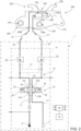
Figures 2 is schematic illustration of a hydraulic arrangement of a work machine, which is adapted to be connected to a quick coupler and is realized according to the present invention. - With reference to
Figure 2 ,number 1 denotes, as a whole, a work machine, in particular an earth-moving machine such as an excavator, a digger, a mechanical shovel or the like. -
Work machine 1 comprises a body movable on the ground via ground engaging wheels or tracks. - In particular, as known, said body preferably comprises: a lower frame or undercarriage, which carries the ground engaging wheels or tracks to allow motion of the body with respect to the ground; and an upper frame or superstructure, which is carried in a rotatable manner by lower frame preferably about a rotation axis orthogonal to the advancing plane of
work machine 1, i.e. orthogonal to the ground. - In addition, as always known,
work machine 1 comprises a hydraulically actuated work implement or work arm, which is carried by the body and is configured to perform multiple earth moving operations, such as digging, handling earth or gravel, loading trucks and/or similar operations. - In particular, said work implement is rotatably carried by the upper frame of
work machine 1. - As per se known, the hydraulically actuated work implement preferably comprises: a boom rotatably carried by the body; and a stick or arm or dipper, which is rotatably carried by the boom and, in turn, is configured to carry in a rotatable manner a work tool, such as buckets, rakes, grapples, asphalt cutters or the like.
- In addition,
work machine 1 preferably comprises a plurality of hydraulic cylinders, in particular double-acting hydraulic cylinders, configured to actuate the hydraulically actuated work implement. - More in detail,
work machine 1 comprises at least one boom actuator, which is operatively interposed between the work machine body and the boom and is configured to rotate the boom with respect to said body. - In addition,
work machine 1 further comprises at least one arm actuator, which is operatively interposed between the boom and the arm and is configured to rotate the arm with respect to the boom. - Preferably,
work machine 1 further comprises also at least one bucket actuator, which is operatively interposed between the arm and the work tool and is configured to rotate the same work tool with respect to the arm. - In addition, with reference to the exemplary embodiment illustrated in
Figure 2 number 200 indicates as a whole a coupling device, in the following referred to also as "quick coupler" or "quick hitch", which is configured to be rotatably carried by the work implement, in particular by the arm ofwork machine 1, and is further configured to allow the connection of the work tool to the same arm. - More in detail, as known,
quick coupler 200 is configured to allow rapid exchange between different work tools without the need for manual intervention by an operator. - In particular,
quick coupler 200 is configured to be interposed between the arm ofwork vehicle 1 and the bucket or other similar work tools. - As known,
quick coupler 200 comprises afirst coupling interface 220 configured to be rotatably carried by the free end of the arm ofwork vehicle 1 opposite to the boom. - In particular,
first coupling interface 220 is preferably configured to be mechanically connected to the free end of the arm ofwork machine 1. - For instance,
first coupling interface 220 may comprise a pair ofholes 230, which are realized on thebody 210 of thequick coupler 200 and are configured to be engaged by respective pins carried by the arm ofwork machine 1, to securely attach thequick coupler 200 to the same arm. - In addition, as always known,
quick coupler 200 comprises asecond coupling interface 240, which is adapted to be mechanically connected to the work tools to be attached to the arm ofwork machine 1. - More in detail, the
second coupling interface 240 comprises a hydraulically actuatedcoupling member 250, which is configured to be coupled to the work tool and is selectively arrangeable in a locking position, in which it is configured to firmly/securely attach the work tool to the samequick coupler 200, and an unlocking position, in which it allows detachment of the work tool fromquick coupler 200 andwork machine 1. - In particular, with reference to the exemplary embodiment illustrated in
Figure 2 , thecoupling member 250 preferably comprises twohooks 250, which are adapted to engage respective pins carried by the work tool, in order to securely attach the same work tool to the arm ofwork machine 1. - Preferably, one of the two
hooks 250 is fixedly/rigidly carried by thebody 210 and the other one between the two hooks 260 is carried in a movable manner and is movable from and towards a locking position, in which it is configured to engage a respective pin of the work tool, in order to firmly attach the same work tool to thequick coupler 200. - In addition, with reference to the exemplary embodiment illustrated in
Figure 2 ,quick coupler 200 comprises ahydraulic actuator 270, in particular a double-effect hydraulic actuator, which is operatively connected to the hydraulically actuatedcoupling member 250 and is configured to selectively operate the same hydraulically actuatedcoupling member 250 in the locking position or in the unlocking position. - In particular, preferably by pressurizing a first
hydraulic port 270a ofhydraulic actuator 270,coupling member 250 is arranged in the locking position, while by pressurizing the otherhydraulic port 270b ofhydraulic actuator 270,coupling member 250 is arranged in the unlocking position. - Clearly, the hydraulic port of the
hydraulic actuator 270 to be pressurized to arrange thecoupling member 250 in the locking position may vary, for instance on the manufacturer and/or the model of thequick coupler 200. - Preferentially, the
hydraulic actuator 270 comprises a double-effecthydraulic cylinder 280. - In use, one chamber of
hydraulic cylinder 280 is configured to be connected to a source of pressurized hydraulic fluid and the other chamber ofhydraulic cylinder 280 is configured to be connected to a tank, a reservoir or the like, in order selectively operate the hydraulically actuatedcoupling member 250 in the locking or in the unlocking position. - In addition,
quick coupler 200 preferably comprises a firsthydraulic port 290a and a secondhydraulic port 290b, which are realized on thebody 210 of the samequick coupler 200, are fluidly connected respectively toport 270a and toport 270b of thehydraulic actuator 270, and are configured to be fluidly connected, on command, to a source of pressurized fluid and to a tank ofwork machine 1, for instance by means of flexible hoses, to allow fluidly connecting the two chambers of thehydraulic actuator 270 to the source of pressurized of hydraulic fluid and to tank. - Preferably, the two
hydraulic ports quick coupler 200. - In addition, a first between
hydraulic ports hydraulic cylinder 270 to arrangecoupling member 250 in the locking position. - The second one between
hydraulic ports hydraulic cylinder 270 to arrangecoupling member 250 in the unlocking position. - In particular, depending on the model or make of the
hydraulic coupler 200, the hydraulic port to be pressurized in order to arrangecoupling member 250 in the looking or unlocking position may change. - With reference to the exemplary embodiment illustrated in
Figure 2 ,work vehicle 1 further comprises a hydraulic arrangement 4, which is configured to be hydraulically connected to thequick coupler 200, in particular to thehydraulic actuator 270 viahydraulic ports hydraulic actuator 270. - More in detail, hydraulic arrangement 4 comprises a source of pressurized
hydraulic fluid 6. Source of pressurizedhydraulic fluid 6, in particular, is configured to provide at outlet a pressurized flow of hydraulic fluid. - Preferably, source of pressurized
hydraulic fluid 6 comprises a hydraulic pump, which is carried by an engine ofwork machine 1 and is adapted to be driven in rotation in order to suck hydraulic fluid from a tank 7 and to provide at outlet a pressurized flow of such hydraulic fluid. - With reference to the exemplary embodiment illustrated in
Figure 2 , hydraulic arrangement 4 further comprises ahydraulic circuit 10, which is configured to be fluidly connected to thequick coupler 200 in order to put thehydraulic actuator 270 in fluid communication with the source of pressurizedhydraulic fluid 6 and with a tank 7. - More in detail,
hydraulic circuit 10 is preferably configured to be fluidly connected toports quick coupler 200. - In particular,
hydraulic circuit 10 comprises a firsthydraulic line 12, in the following referred to as "high-pressure hydraulic line", which is configured to fluidly connect the outlet of the source of pressurizedhydraulic fluid 6 with thequick coupler 200, particular with thehydraulic actuator 270. - In addition,
hydraulic circuit 10 comprises a secondhydraulic line 14, in the following referred to as "low pressure hydraulic line", which is configured to fluidly connect thequick coupler 200, in particular thehydraulic actuator 270 with tank 7. - With reference to the preferred embodiment illustrated in
Figure 2 ,hydraulic circuit 10 further comprises avalve assembly 16, which is adapted to be fluidly interposed between the high-pressure line, the low-pressure line and thehydraulic actuator 270 ofquick coupler 200 and is configured to control the flow of pressurized hydraulic fluid provided to the samehydraulic actuator 270. - More in detail,
valve assembly 16 is preferably configured to be fluidly connected to thefirst port 290a and to thesecond port 290b ofquick coupler 200, via a firsthydraulic line 18 and via a secondhydraulic line 20. - In particular,
valve assembly 16 is configured to selectively fluidly connect, on command, a first one between firsthydraulic port 290a and a secondhydraulic port 290b with firsthydraulic line 12, and a second one between firsthydraulic port 290a and a secondhydraulic port 290b with secondhydraulic line 14. - First
hydraulic line 18 and secondhydraulic line 20 preferably comprise each aflexible hose work machine 1 body with thequick coupler 200 carried by the hydraulically actuated work implement, in particular by the arm. -
Flexible hoses - In particular,
flexible hoses work vehicle 1. - With reference to the exemplary embodiment illustrated in
Figure 2 ,flexible hose 19 is adapted to be fluidly connected toport 290b, andflexible hose 21 is adapted to be fluidly connected toport 290a, in order to avoid crossing offlexible hoses - In addition,
line 18 preferably connectsvalve assembly 16 withport 290b ofquick coupler 200, whileline 20 preferably connectsvalve assembly 16 withport 290a ofquick coupler 200. - With reference to the exemplarity illustrated in
Figure 2 ,valve assembly 16 preferably comprises a four-ways three-positions valve 22, in particular solenoid-controlled valve. - A
first port 22a ofvalve 22 is preferably fluidly connected to the high-pressure line 12 and tosource 6 and asecond port 22b ofvalve 22 is preferably fluidly connected to low-pressure line 14 and to tank 7. - Preferably, the two
other ports valve 22 are configured to be fluidly connected to thehydraulic actuator 270. - More in detail, the two
ports valve 22 are preferably configured to be fluidly connected to hydraulic ports 290 ofquick coupler 200 vialine 18 andline 20 respectively. - In a first position or neutral position, illustrated in
Figure 2 ,valve 22 is preferably configured to put the twoports hydraulic actuator 270 in fluid communication with low-pressure line 14 and to fluidly isolate high-pressure line 12. - More in detail, in the first position,
valve 22 is preferably configured to put the twoports lines pressure line 14 and to fluidly isolate high-pressure line 12. - Preferably,
valve 22 comprises biasing means 23 configured to biasvalve 22 in the first position. - In the second position,
valve 22 is preferably configured to putport 270a ofhydraulic actuator 270, inparticular port 290a, in fluid communication with high-pressure line 12 andport 270b of hydraulic actuator 27, inparticular port 290b, in fluid communication with low-pressure line 14. - Vice-versa, in the third position,
valve 22 is preferably configured to putport 270a ofhydraulic actuator 270, inparticular port 290a, in fluid communication with low-pressure line 14 andport 270b of hydraulic actuator 27, inparticular port 290b, in fluid communication with high-pressure line 12. - In other words, in the second position,
valve 22 is preferably configured to putport 290a andline 20 in fluid communication with high-pressure line 12 and aport 290b andline 18 in fluid communication with low-pressure line 14. - Vice-versa, in the third position,
valve 22 is preferably configured to putport 290b andline 18 in fluid communication with high-pressure line 12 and aport 290a andline 20 in fluid communication with low-pressure line 14. - Preferably,
valve assembly 16 further comprises twosolenoids 26, which are operable to selectively arrangevalve 22 in the second or in the third position. - With reference to the exemplary embodiment illustrated in
Figure 2 , hydraulic arrangement 4 preferably comprises twocheck valves line downstream valve assembly 16. - Check
valve source 6 andvalve assembly 22 towards thehydraulic coupler 200. - In addition,
check valves - More in detail, hydraulic arrangement 4 preferably comprises a
first pilot line 29, which fluidly connectsport 22c withcheck valve 30, and is configured to opencheck valve 30 whenvalve 22 is arranged on the third position, i.e. whenline 18 is pressurized, so as to opencheck valve 30 and allow to discharge the pressurized hydraulic fluid contained withinline 20, betweenhydraulic coupler 200 and thesame check valve 30. - Moreover, hydraulic arrangement 4 preferably comprises a
second pilot line 31, which fluidly connectsport 22d withcheck valve 28, and is configured to opencheck valve 28 whenvalve 22 is arranged on the second position, i.e. whenline 20 is pressurized, so as to opencheck valve 28 and allow to discharge the pressurized hydraulic fluid contained withinline 18, betweenhydraulic coupler 200 and thesame check valve 28. - With reference to the exemplary embodiment illustrated in
Figure 2 ,work machine 1 preferably further comprises anelectronic control unit 40, which is operatively connected at least tovalve assembly 16 and is provided with elaboration means configured to control the operation of thesame valve assembly 16. - More in detail,
electronic control unit 40 is preferably electronically connected tosolenoids 26 and is configured to control its operation. - Preferentially,
work machine 1 further comprises aninput device 42, such as a knob, a button, a portion of a touch-sensitive screen or similar HMIs, which allow the operator to impart a command to control the operation ofvalve assembly 16. -
Electronic control unit 40 is preferably electronically connected to inputdevice 42 and is configured to control the operation ofvalve assembly 16, in particular ofsolenoids 26, as function of the commands imparted by the user via the input device. - In particular,
input device 42 is preferably configured to output to electronic control unit 40 a first or locking command to arrangecoupling member 250 in the locking position and a second or unlocking command to arrangecoupling member 250 in the unlocking position. - In particular,
input device 42 is configured to allow the user to operatevalve assembly 16 in order to selectively arrange thecoupling member 250 in the locking or in the unlocking position, to lock or unlock the work tool accordingly. - More in detail,
electronic control unit 40, in response to the command received from input means 42, is configured to control operation ofvalve assembly 16 as function of the position ofports quick coupler 200, in order to avoid crossing offlexible hoses - Input means 42 are preferably further configured to allow the user to impart commands associated to the relative position of the
hydraulic ports quick coupler 200. - In particular, with reference to the exemplary embodiment illustrated in
Figure 2 , ifhydraulic ports 290a is configured to receive pressurized hydraulic fluid in order to controlhydraulic cylinder 270 to arrangecoupling member 250 in the locking position,electronic control unit 40 may be configured to arrangevalve 22 in its second position to arrangecoupling member 250 in the locking position. - Vice-versa, if
hydraulic port 290b is configured to receive pressurized hydraulic fluid in order to controlhydraulic cylinder 270 to arrangecoupling member 250 in the locking position,electronic control unit 40 may be configured to arrangevalve 22 in its third position to arrangecoupling member 250 in the locking position. - In addition, according to the preferred embodiment of the present invention, the
electronic control unit 40 and theinput device 42 are preferably configured to allow the user to control the operation of hydraulic arrangement 4 and therefore ofquick coupler 200, in particular ofcoupling member 250, according to the ISO standard 13031:2013 (Earth moving machinery - Quick couplers - Safety). - The operation of the above-described
work machine 1 is easy inferable from what above and is briefly the following. - In use, the operator attaches the
quick coupler 200 to the arm ofwork machine 1 and then engages, with the samequick coupler 200, the work tool to be attached to the arm ofwork machine 1. - In particular, the operator connects the
flexible hoses respective ports - To lock the work tool to the
quick coupler 200 and to arm ofwork machine 1, operator imparts command viainput device 42 to arrange valve assembly in the second or in the third position, to pressurize the relative chamber ofhydraulic actuator 270 and engagecoupling member 250, thus safely and stably connecting the work tool toquick coupler 200. - Clearly, the position in which the valve has to be arranged depend on the chamber of the
hydraulic actuator 270 to be pressurized to move thecoupling member 250 in the locking position. - To disengage the
quick coupler 200 from the work tool, on the other hand,valve assembly 16 is arranged in the opposite position with respect to the locking phase, i.e. respectively in the third or in the second position. - More in detail, the operator imparts command via user input means 42 related to the position/configuration of
hydraulic ports quick coupler 200. - In particular, the operator imparts command via user input means 42 to indicate which one between
hydraulic ports hydraulic cylinder 270 to arrangecoupling member 250 in the locking position. - Then, when operator imparts commands via user input means 42 to arrange
coupling member 250 in the locking position,electronic control unit 40controls valve assembly 22 depending on the position/configuration ofhydraulic ports - More in detail, when operator imparts commands via user input means 42 to arrange
coupling member 250 in the locking position andhydraulic port 290a is configured to receive pressurized hydraulic fluid in order to controlhydraulic cylinder 270 to arrangecoupling member 250 in the locking position,electronic control unit 40 arrangesvalve 22 in its second position. - Vice-versa, when operator imparts commands via user input means 42 to arrange
coupling member 250 in the locking position andhydraulic port 290b is configured to receive pressurized hydraulic fluid in order to controlhydraulic cylinder 270 to arrangecoupling member 250 in the locking position,electronic control unit 40 arrangesvalve 22 in its third position. - In view of the foregoing, the present invention is further directed to a method for controlling hydraulic arrangement 4, which comprises the following steps:
- a) determining which one between
hydraulic port hydraulic cylinder 270 to arrangecoupling member 250 in the locking position, - b) receiving a control signal to arrange
coupling member 250 in the locking position, - c) if
hydraulic port 290a is configured to receive pressurized hydraulic fluid in order to controlhydraulic cylinder 270 to arrangecoupling member 250 in the locking position, arrangingvalve 22 in its second position, or vice-versa, - d) if
hydraulic port 290b is configured to receive pressurized hydraulic fluid in order to controlhydraulic cylinder 270 to arrangecoupling member 250 in the locking position, arrangingvalve 22 in its third position. - The method may further comprise the followings steps:
- e) receiving a control signal to arrange
coupling member 250 in the unlocking position, - f) if
hydraulic port 290b is configured to receive pressurized hydraulic fluid in order to controlhydraulic cylinder 270 to arrangecoupling member 250 in the unlocking position, arrangingvalve 22 in its second position, or vice-versa, - g) if
hydraulic port 290a is configured to receive pressurized hydraulic fluid in order to controlhydraulic cylinder 270 to arrangecoupling member 250 in the unlocking position, arrangingvalve 22 in its third position. - In view of the foregoing, the advantages of a hydraulic arrangement 4 according to the present invention are considerable and apparent.
- In fact, it is apparent from the above that hydraulic arrangement 4 allows to connect
quick couplers 200 having alsohydraulic ports hydraulic actuators ports flexible hoses valve assembly 16, which is configured to be able to pressurize selectively and alternatively both ends the same hydraulic cylinder depending on the position it is arranged. - Be avoiding crossing the
flexible hoses - Lastly, the presence of the two
check valves lines same check valve quick coupler 200, in order to maintain thecoupling member 250 securely arranged in the locking position and prevent accidental detachment of the work tool even if there are pressure drops in the hydraulic arrangement 4, thus increasing massively the safety associated withwork machine 1. Un unwanted detachment of a bucket or a similar, work tool when the hydraulically actuated work implement ofwork machine 1 is lifted from the ground, indeed, might also result in a fatal accident. - It is clear that modifications can be made to the described hydraulic arrangement 4, to the
related work machine 1 and to thequick coupler 200 which do not extend beyond the scope of protection defined by the claims.
Claims (13)
- A hydraulic arrangement (4) for a work machine (1), said work machine comprising a body movable on the ground via ground engaging means and a hydraulically actuated arm carried by said body;said hydraulic arrangement (4) being configured to be fluidly connected to a coupling device (200), wherein said coupling device (200) is provided with:• a first coupling interface (220), which is configured to be connected to said arm;• a second coupling interface (240), which is configured to be selectively connected to a work tool, in order to allow connecting said work tool to said hydraulically actuated arm,• a hydraulically actuated coupling member (250), which is configured to be coupled to said work tool and is selectively operable in a locking position and in an unlocking position;• a hydraulic actuator (270), which is operatively connected to said hydraulically actuated coupling member (250), is configured to be fluidly connected to said hydraulic arrangement (4) and is configured to selectively arrange said hydraulically actuated coupling member (250) in the locking position or in the unlocking position;• a first hydraulic port (290a) and a second hydraulic port (290b), which are realized on a body (210) of said quick coupler (200) and are fluidly to a respective inlet (270a, 270b) of said hydraulic actuator (270),said hydraulic arrangement (4) comprising:• a source of pressurized hydraulic fluid (6); and• a hydraulic circuit (10) configured to fluidly connect said source of pressurized hydraulic fluid (6) with said hydraulic actuator (270);said hydraulic circuit comprising:• a first hydraulic line (12), which is configured to fluidly connect said source of pressurized hydraulic fluid (6) with said hydraulic actuator (270);• a second hydraulic line (14) configured to fluidly connect a tank (7) with said hydraulic actuator (270); and• a valve assembly (16), which is configured to be fluidly interposed between said first hydraulic line (12), said second hydraulic line (14) and said hydraulic actuator (270), and is configured to selectively fluidly connect, on command, a first one between said first hydraulic port (290a) and a second hydraulic port (290b) with said first hydraulic line (12), and a second one between between said first hydraulic port (290a) and a second hydraulic port (290b) with said second hydraulic line (14), and• an electronic control unit (40), which is operatively connected to said valve assembly (16) and to said user input means (42) and comprises elaboration means configured to control the operation of said valve assembly (16) as function of the relative position of said first hydraulic port (290a) and a second hydraulic port (290b).
- Hydraulic arrangement according to claim 1, further comprising user input means (42) configured to impart commands to arrange said coupling member (250) on said locking position or said unlocking position, and commands associated to the relative position of said hydraulic ports (290a) and (290b),
said electronic control unit (40) being configured to control the operation of said valve assembly (16) on the basis of the commands received by said user input means (42). - Hydraulic arrangement according to claim 1 or 2, wherein said valve assembly (16) comprises a solenoid-controlled valve (22).
- Hydraulic arrangement according to any of claims 1 to 3, wherein said valve assembly (16) comprises a four-way three-position hydraulic valve (22).
- Hydraulic arrangement according to claim 4, wherein:a first port (22a) of said hydraulic valve (22) is configured to be fluidly connected to said first hydraulic line (12);a second port (22b) of said hydraulic valve (22) is configured to be fluidly connected to said second hydraulic line (14); anda third (22c) and a fourth (22d) ports of said hydraulic valve (22) is configured to be fluidly connected to respective ports (270b, 270a) of said hydraulic actuator (270).
- Hydraulic arrangement according to claim 4 or 5, wherein said valve (22):in a first position is configured to put the said first port (290a) and said second port (290b) in fluid communication with said low-pressure line (14) and to fluidly isolate said high-pressure line (12),in a second position is configured to put said first port (290a) in fluid communication with high pressure line (12) and said second port (290b) in fluid communication with low pressure line (14), andin a third position is configured to put said first port (290a) in fluid communication with low pressure line (14) and said second port (290b) in fluid communication with high pressure line (12).
- Hydraulic arrangement according to claim 5 or 6, further comprising a first check valve (28) and a second check valve (30) arranged downstream said valve assembly (16), respectively along a third hydraulic line (18) configured to fluidly connect the third port (22c) of said hydraulic valve (22) to said second port (270b) of said hydraulic actuator (270) and along a fourth hydraulic line (19) configured to fluidly connect the fourth port (22d) of said hydraulic valve (22) to said first port (270a) of said hydraulic actuator (270) .
- Hydraulic arrangement according to claim 7, further comprising a first pilot line (31) configured to fluidly connect said first check valve (28) to said fourth line (20), in order to allow to open said first check valve (28) when said hydraulic valve (22) is arranged in said third position; and
a second pilot line (29) configured to fluidly connect said second check valve (30) to said third line (18), in order to allow to open said second check valve (30) when said hydraulic valve (22) is arranged in said second position. - Hydraulic arrangement according to claim 6, 7 or 8, wherein if the first one between said first hydraulic port (290a) and said second hydraulic port (290b) is configured to receive pressurized hydraulic fluid to arrange said control member (250) in the locking position, electronic control unit (40) is configured to arrange said valve (22) in its second position, and
if the second one between said first hydraulic port (290a) and said second hydraulic port (290b) is configured to receive pressurized hydraulic fluid to arrange said control member (250) in the locking position, electronic control unit (40) is configured to arrange said valve (22) in its third position. - Hydraulic arrangement according to claim 9, wherein user input means (42) are configured to output signals to said control unit (40) adapted to indicate which one between said first hydraulic port (290a) and said second hydraulic port (290b) is configured to receive pressurized hydraulic fluid in order to arrange coupling member 250 in said locking position.
- A work machine (1) comprising a body movable on the ground via ground engaging means, a hydraulically actuated arm carried by said body, and a hydraulic arrangement (4) as claimed in any one of the preceding claims.
- A combination comprising a work machine (1) as claimed in claim 11 and a coupling device (200) comprising:• a first coupling interface (220), which is configured to be connected to said arm,• a second coupling interface (240), which is configured to be selectively connected to a work tool, in order to allow connecting said work tool to said hydraulically actuated arm, and comprises a hydraulically actuated coupling member (250), which is configured to be coupled to said work tool and is selectively operable in a locking position and in an unlocking position,• a hydraulic actuator (270), which is operatively connected to said hydraulically actuated coupling member (250), is configured to be fluidly connected to said hydraulic arrangement and is configured to selectively arrange said hydraulically actuated coupling member (250) in the locking position or in the unlocking position, and• a first hydraulic port (290a) and a second hydraulic port (290b), which are realized on a body (210) of said quick coupler (200) and are fluidly to a respective inlet (270a, 270b) of said hydraulic actuator (270).
- A method of operation of a hydraulic arrangement realized according to any of claims 6 to 10,
said method comprising the steps of:a) determining which one between said first hydraulic port (290a) and said second hydraulic port (290b) is configured to receive pressurized hydraulic fluid in order to arrange said coupling member (250) in said locking position,b) receiving a control signal to arrange said coupling member (250) in said locking position,c) if the first one between hydraulic port (290a) and second hydraulic port (290b) is configured to receive pressurized hydraulic fluid in order to arrange said coupling member (250) in said the locking position, arranging said valve (22) in its second position, or vice-versa,d) if the second one between hydraulic port (290a) and second hydraulic port (290b) is configured to receive pressurized hydraulic fluid in order to arrange said coupling member (250) in said the locking position, arranging said valve (22) in its third position.
Applications Claiming Priority (1)
| Application Number | Priority Date | Filing Date | Title |
|---|---|---|---|
| IT202300021156 | 2023-10-11 |
Publications (1)
| Publication Number | Publication Date |
|---|---|
| EP4538467A1 true EP4538467A1 (en) | 2025-04-16 |
Family
ID=89157938
Family Applications (1)
| Application Number | Title | Priority Date | Filing Date |
|---|---|---|---|
| EP24205943.4A Pending EP4538467A1 (en) | 2023-10-11 | 2024-10-10 | Improved hydraulic arrangement for a work machine, work machine provided with such hydraulic arrangement and combination of such work machine and a coupling device |
Country Status (1)
| Country | Link |
|---|---|
| EP (1) | EP4538467A1 (en) |
Citations (6)
| Publication number | Priority date | Publication date | Assignee | Title |
|---|---|---|---|---|
| US5147173A (en) * | 1991-06-03 | 1992-09-15 | Caterpillar Inc. | Coupling device |
| JPH11269910A (en) * | 1998-03-26 | 1999-10-05 | Komatsu Ltd | Work machine attachments |
| EP2018458B1 (en) * | 2006-05-10 | 2017-09-27 | Oilquick AB | Valve block, tool attachment, a working machine and the use of a valve block |
| GB2601859A (en) * | 2020-12-14 | 2022-06-15 | Caterpillar Sarl | Hydraulic control system and method for a bucket shake operation in a work machine with a hydraulic pump and unloader valve |
| US20230160172A1 (en) | 2021-11-23 | 2023-05-25 | Caterpillar Inc. | Quick coupler automatic locking mechanism and method |
| CN116733801A (en) * | 2023-06-20 | 2023-09-12 | 徐工集团工程机械股份有限公司科技分公司 | Skid steer loader accessory quick change system and control method thereof |
-
2024
- 2024-10-10 EP EP24205943.4A patent/EP4538467A1/en active Pending
Patent Citations (6)
| Publication number | Priority date | Publication date | Assignee | Title |
|---|---|---|---|---|
| US5147173A (en) * | 1991-06-03 | 1992-09-15 | Caterpillar Inc. | Coupling device |
| JPH11269910A (en) * | 1998-03-26 | 1999-10-05 | Komatsu Ltd | Work machine attachments |
| EP2018458B1 (en) * | 2006-05-10 | 2017-09-27 | Oilquick AB | Valve block, tool attachment, a working machine and the use of a valve block |
| GB2601859A (en) * | 2020-12-14 | 2022-06-15 | Caterpillar Sarl | Hydraulic control system and method for a bucket shake operation in a work machine with a hydraulic pump and unloader valve |
| US20230160172A1 (en) | 2021-11-23 | 2023-05-25 | Caterpillar Inc. | Quick coupler automatic locking mechanism and method |
| CN116733801A (en) * | 2023-06-20 | 2023-09-12 | 徐工集团工程机械股份有限公司科技分公司 | Skid steer loader accessory quick change system and control method thereof |
Similar Documents
| Publication | Publication Date | Title |
|---|---|---|
| CN105229239B (en) | Quick connector hydraulic control system for the equipment of work machine | |
| US8281506B2 (en) | Tool coupler assembly | |
| JP5764968B2 (en) | Hydraulic control equipment for construction machinery | |
| KR101975063B1 (en) | Construction machinery and hydraulic circuit thereof | |
| CA2433120C (en) | Hydraulic control arrangement for a mobile operating machine | |
| CN103104004B (en) | Engineering machinery | |
| EP4522811B1 (en) | Universal hydraulic auxiliary depressurization circuit and method of depressurizing a work tool auxiliary circuit of a work machine | |
| EP2094915B1 (en) | Hydraulic system for improving flatting workability in an excavator | |
| EP2652214B1 (en) | Flow regeneration hydraulic circuit | |
| US8621860B2 (en) | Control system for work vehicle | |
| JP5614972B2 (en) | Work machine | |
| EP3184699B1 (en) | A coupling apparatus | |
| JP7569472B2 (en) | Construction Machinery | |
| JP7856383B2 (en) | Automated work tool pressure reduction circuit and method | |
| JP2017187144A (en) | Work machine | |
| EP4660381A1 (en) | Improved work machine and control method thereof | |
| EP4729701A1 (en) | Improved work machine and control method thereof | |
| EP3821136B1 (en) | Hydraulic machine comprising a hydraulic circuit | |
| JP5885787B2 (en) | Hydraulic control device | |
| EP4575104A1 (en) | Improved work machine | |
| JP5498325B2 (en) | Hydraulic control circuit for work machines | |
| JP4423149B2 (en) | Construction machinery | |
| KR20090070530A (en) | Seat-linked hydraulic control system for backhoe loaders | |
| KR20250151366A (en) | Tiltrotator arrangement including tiltrotator and valve | |
| CN119301328A (en) | Valve device for mobile working machines with hydraulic loads |
Legal Events
| Date | Code | Title | Description |
|---|---|---|---|
| PUAI | Public reference made under article 153(3) epc to a published international application that has entered the european phase |
Free format text: ORIGINAL CODE: 0009012 |
|
| STAA | Information on the status of an ep patent application or granted ep patent |
Free format text: STATUS: THE APPLICATION HAS BEEN PUBLISHED |
|
| AK | Designated contracting states |
Kind code of ref document: A1 Designated state(s): AL AT BE BG CH CY CZ DE DK EE ES FI FR GB GR HR HU IE IS IT LI LT LU LV MC ME MK MT NL NO PL PT RO RS SE SI SK SM TR |
|
| STAA | Information on the status of an ep patent application or granted ep patent |
Free format text: STATUS: REQUEST FOR EXAMINATION WAS MADE |
|
| 17P | Request for examination filed |
Effective date: 20251016 |
|
| GRAP | Despatch of communication of intention to grant a patent |
Free format text: ORIGINAL CODE: EPIDOSNIGR1 |
|
| STAA | Information on the status of an ep patent application or granted ep patent |
Free format text: STATUS: GRANT OF PATENT IS INTENDED |
|
| INTG | Intention to grant announced |
Effective date: 20260317 |
|
| GRAS | Grant fee paid |
Free format text: ORIGINAL CODE: EPIDOSNIGR3 |
|
| GRAA | (expected) grant |
Free format text: ORIGINAL CODE: 0009210 |
|
| STAA | Information on the status of an ep patent application or granted ep patent |
Free format text: STATUS: THE PATENT HAS BEEN GRANTED |