EP4538088A1 - Unit - Google Patents
Unit Download PDFInfo
- Publication number
- EP4538088A1 EP4538088A1 EP23818224.0A EP23818224A EP4538088A1 EP 4538088 A1 EP4538088 A1 EP 4538088A1 EP 23818224 A EP23818224 A EP 23818224A EP 4538088 A1 EP4538088 A1 EP 4538088A1
- Authority
- EP
- European Patent Office
- Prior art keywords
- gear
- case
- bearing
- planetary gear
- differential
- Prior art date
- Legal status (The legal status is an assumption and is not a legal conclusion. Google has not performed a legal analysis and makes no representation as to the accuracy of the status listed.)
- Pending
Links
Images

Classifications
-
- H—ELECTRICITY
- H02—GENERATION; CONVERSION OR DISTRIBUTION OF ELECTRIC POWER
- H02K—DYNAMO-ELECTRIC MACHINES
- H02K7/00—Arrangements for handling mechanical energy structurally associated with dynamo-electric machines, e.g. structural association with mechanical driving motors or auxiliary dynamo-electric machines
- H02K7/10—Structural association with clutches, brakes, gears, pulleys or mechanical starters
- H02K7/116—Structural association with clutches, brakes, gears, pulleys or mechanical starters with gears
-
- B—PERFORMING OPERATIONS; TRANSPORTING
- B60—VEHICLES IN GENERAL
- B60K—ARRANGEMENT OR MOUNTING OF PROPULSION UNITS OR OF TRANSMISSIONS IN VEHICLES; ARRANGEMENT OR MOUNTING OF PLURAL DIVERSE PRIME-MOVERS IN VEHICLES; AUXILIARY DRIVES FOR VEHICLES; INSTRUMENTATION OR DASHBOARDS FOR VEHICLES; ARRANGEMENTS IN CONNECTION WITH COOLING, AIR INTAKE, GAS EXHAUST OR FUEL SUPPLY OF PROPULSION UNITS IN VEHICLES
- B60K1/00—Arrangement or mounting of electrical propulsion units
-
- F—MECHANICAL ENGINEERING; LIGHTING; HEATING; WEAPONS; BLASTING
- F16—ENGINEERING ELEMENTS AND UNITS; GENERAL MEASURES FOR PRODUCING AND MAINTAINING EFFECTIVE FUNCTIONING OF MACHINES OR INSTALLATIONS; THERMAL INSULATION IN GENERAL
- F16H—GEARING
- F16H37/00—Combinations of mechanical gearings, not provided for in groups F16H1/00 - F16H35/00
- F16H37/02—Combinations of mechanical gearings, not provided for in groups F16H1/00 - F16H35/00 comprising essentially only toothed or friction gearings
- F16H37/06—Combinations of mechanical gearings, not provided for in groups F16H1/00 - F16H35/00 comprising essentially only toothed or friction gearings with a plurality of driving or driven shafts; with arrangements for dividing torque between two or more intermediate shafts
- F16H37/08—Combinations of mechanical gearings, not provided for in groups F16H1/00 - F16H35/00 comprising essentially only toothed or friction gearings with a plurality of driving or driven shafts; with arrangements for dividing torque between two or more intermediate shafts with differential gearing
- F16H37/0806—Combinations of mechanical gearings, not provided for in groups F16H1/00 - F16H35/00 comprising essentially only toothed or friction gearings with a plurality of driving or driven shafts; with arrangements for dividing torque between two or more intermediate shafts with differential gearing with a plurality of driving or driven shafts
- F16H37/0813—Combinations of mechanical gearings, not provided for in groups F16H1/00 - F16H35/00 comprising essentially only toothed or friction gearings with a plurality of driving or driven shafts; with arrangements for dividing torque between two or more intermediate shafts with differential gearing with a plurality of driving or driven shafts with only one input shaft
- F16H37/082—Combinations of mechanical gearings, not provided for in groups F16H1/00 - F16H35/00 comprising essentially only toothed or friction gearings with a plurality of driving or driven shafts; with arrangements for dividing torque between two or more intermediate shafts with differential gearing with a plurality of driving or driven shafts with only one input shaft and additional planetary reduction gears
-
- F—MECHANICAL ENGINEERING; LIGHTING; HEATING; WEAPONS; BLASTING
- F16—ENGINEERING ELEMENTS AND UNITS; GENERAL MEASURES FOR PRODUCING AND MAINTAINING EFFECTIVE FUNCTIONING OF MACHINES OR INSTALLATIONS; THERMAL INSULATION IN GENERAL
- F16H—GEARING
- F16H57/00—General details of gearing
- F16H57/02—Gearboxes; Mounting gearing therein
- F16H57/021—Shaft support structures, e.g. partition walls, bearing eyes, casing walls or covers with bearings
-
- B—PERFORMING OPERATIONS; TRANSPORTING
- B60—VEHICLES IN GENERAL
- B60K—ARRANGEMENT OR MOUNTING OF PROPULSION UNITS OR OF TRANSMISSIONS IN VEHICLES; ARRANGEMENT OR MOUNTING OF PLURAL DIVERSE PRIME-MOVERS IN VEHICLES; AUXILIARY DRIVES FOR VEHICLES; INSTRUMENTATION OR DASHBOARDS FOR VEHICLES; ARRANGEMENTS IN CONNECTION WITH COOLING, AIR INTAKE, GAS EXHAUST OR FUEL SUPPLY OF PROPULSION UNITS IN VEHICLES
- B60K1/00—Arrangement or mounting of electrical propulsion units
- B60K2001/001—Arrangement or mounting of electrical propulsion units one motor mounted on a propulsion axle for rotating right and left wheels of this axle
-
- F—MECHANICAL ENGINEERING; LIGHTING; HEATING; WEAPONS; BLASTING
- F16—ENGINEERING ELEMENTS AND UNITS; GENERAL MEASURES FOR PRODUCING AND MAINTAINING EFFECTIVE FUNCTIONING OF MACHINES OR INSTALLATIONS; THERMAL INSULATION IN GENERAL
- F16H—GEARING
- F16H1/00—Toothed gearings for conveying rotary motion
- F16H1/02—Toothed gearings for conveying rotary motion without gears having orbital motion
- F16H1/20—Toothed gearings for conveying rotary motion without gears having orbital motion involving more than two intermeshing members
-
- F—MECHANICAL ENGINEERING; LIGHTING; HEATING; WEAPONS; BLASTING
- F16—ENGINEERING ELEMENTS AND UNITS; GENERAL MEASURES FOR PRODUCING AND MAINTAINING EFFECTIVE FUNCTIONING OF MACHINES OR INSTALLATIONS; THERMAL INSULATION IN GENERAL
- F16H—GEARING
- F16H1/00—Toothed gearings for conveying rotary motion
- F16H1/28—Toothed gearings for conveying rotary motion with gears having orbital motion
-
- F—MECHANICAL ENGINEERING; LIGHTING; HEATING; WEAPONS; BLASTING
- F16—ENGINEERING ELEMENTS AND UNITS; GENERAL MEASURES FOR PRODUCING AND MAINTAINING EFFECTIVE FUNCTIONING OF MACHINES OR INSTALLATIONS; THERMAL INSULATION IN GENERAL
- F16H—GEARING
- F16H57/00—General details of gearing
- F16H57/02—Gearboxes; Mounting gearing therein
- F16H2057/02034—Gearboxes combined or connected with electric machines
-
- F—MECHANICAL ENGINEERING; LIGHTING; HEATING; WEAPONS; BLASTING
- F16—ENGINEERING ELEMENTS AND UNITS; GENERAL MEASURES FOR PRODUCING AND MAINTAINING EFFECTIVE FUNCTIONING OF MACHINES OR INSTALLATIONS; THERMAL INSULATION IN GENERAL
- F16H—GEARING
- F16H37/00—Combinations of mechanical gearings, not provided for in groups F16H1/00 - F16H35/00
- F16H37/02—Combinations of mechanical gearings, not provided for in groups F16H1/00 - F16H35/00 comprising essentially only toothed or friction gearings
- F16H37/04—Combinations of toothed gearings only
- F16H37/041—Combinations of toothed gearings only for conveying rotary motion with constant gear ratio
Definitions
- the present invention relates to a unit.
- a unit can be easily reduced in size.
- the planetary gear mechanism 51 is located only in the region inside the first case 21 rather than in a region inside the fourth case 24, the first gear 52 and the second gear 53 can be disposed closer to the motor 3 in the axial direction X than in a configuration in which the planetary gear mechanism 51 is disposed in a region inside the fourth case 24. As a result, this can contribute to reduce the unit 1 in size (in particular, in the axial direction X).
- the sun gear 511 is coupled to the rear end of the rotation shaft 31 to rotate integrally with the rotation shaft 31.
- the carrier 512 is coupled to the front end of the first shaft 7 to rotate integrally with the first shaft 7.
- the first shaft 7 is rotatably supported by the third case 23 and the fourth case 24 via the bearing B5 and the bearing B7.
- An axis of the rotation shaft 31 and an axis of the first shaft 7 are both an axis C1 serving as a first axis.
- the differential case 561 accommodates the differential unit 562.
- the differential case 561 is rotatably supported by the first case 21 and the fourth case 24 via the bearing B2 and the bearing B9.
- the differential case 561 is coupled to an inner periphery of the fourth gear 55 to rotate integrally with the fourth gear 55.
- the fourth gear 55 and the differential gear 56 are disposed coaxially with the axis C3.
- the differential gear 56 is disposed closer to the planetary gear mechanism 51 than the fourth gear 55. That is, the differential gear 56 has a portion that is located between the planetary gear mechanism 51 and the fourth gear 55.
- the space is generated radially outward from the space in which the planetary gear mechanism 51 is disposed, and this space can be effectively utilized by forming the inverter accommodating chamber S1 in this space, which can contribute to reducing the entire unit 1 in size.
Landscapes
- Engineering & Computer Science (AREA)
- General Engineering & Computer Science (AREA)
- Mechanical Engineering (AREA)
- Chemical & Material Sciences (AREA)
- Combustion & Propulsion (AREA)
- Transportation (AREA)
- Power Engineering (AREA)
- Retarders (AREA)
- General Details Of Gearings (AREA)
- Connection Of Motors, Electrical Generators, Mechanical Devices, And The Like (AREA)
Abstract
Description
- The present invention relates to a unit.
-
Patent Document 1 discloses a unit including a speed reduction mechanism. - Patent Document 1:
JP2022-33113A - An object of the present invention is to provide a unit that can be easily reduced in size.
- According to an embodiment of the present invention, a unit is provided. The unit includes: a rotating electrical machine; a planetary gear mechanism connected downstream of the rotating electrical machine; a first gear connected downstream of the planetary gear mechanism; a second gear to mesh with the first gear; and a third gear connected downstream of the second gear. The rotating electrical machine, the planetary gear mechanism, and the first gear are disposed along a first axis, the second gear and the third gear are disposed along a second axis, and the third gear has a portion sandwiched between the planetary gear mechanism and the second gear.
- According to an embodiment of the present invention, a unit can be easily reduced in size.
-
- [
FIG. 1] FIG. 1 is a schematic configuration diagram of a unit according to the present embodiment. - [
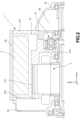
FIG. 2] FIG. 2 is a longitudinal sectional view illustrating positional relation between an inverter and a planetary gear mechanism. - Hereinafter, an embodiment of the present invention (hereinafter, simply referred to as the present embodiment) will be described with reference to the accompanying drawings.
- First, a
unit 1 according to the present embodiment will be described with reference toFIGS. 1 and2 . In the present specification, the same elements are denoted by the same reference numerals throughout the drawings. -
FIG. 1 is a schematic configuration diagram of theunit 1 according to the present embodiment.FIG. 2 is a longitudinal sectional view illustrating positional relation between an inverter 4 and aplanetary gear mechanism 51. - The
unit 1 illustrated inFIGS. 1 and2 is used to drive driving wheels (not illustrated) of a vehicle, but is not limited thereto, and may be used, for example, to drive an electrical product. Theunit 1 can also be referred to as a motor unit (a unit including at least a motor), a power transmission device (a device including at least a power transmission mechanism (for example, a gear mechanism and/or a differential gear mechanism)), or the like. The device (unit) including the motor and the power transmission mechanism belongs to concepts of both the motor unit and the power transmission device. Specifically, theunit 1 includes ahousing 2, amotor 3 serving as a rotating electrical machine, an inverter 4, areduction gear group 5 serving as a power transmission mechanism, and adrive shaft 6. - The
housing 2 is an accommodating member that accommodates themotor 3, the inverter 4, thereduction gear group 5, and thedrive shaft 6. Thehousing 2 includes one or more cases. Specifically, thehousing 2 includes afirst case 21, asecond case 22, athird case 23 serving as a third wall portion, afourth case 24, and a fifth case 25 (seeFIG. 2 ). - The
first case 21 is a 3in1 case. 3in1 means a form in which a part of a motor case, which accommodates themotor 3 and thedrive shaft 6, and a part of an inverter case, which accommodates the inverter 4, are integrally formed. - The
first case 21 includes: acylinder 211 that is provided to be open at least at a front end that is one end; afront flange 212 that is provided to protrude toward an outer peripheral side at the front end of thecylinder 211; arear flange 213 that is provided to protrude toward an outer peripheral side at a rear end that is the other end of thecylinder 211; and asupport frame 214 that is disposed on an inner peripheral side of thecylinder 211 to be located at the rear end of thecylinder 211. Here, an axial direction X means an axial direction X of a rotation shaft of a component that constitutes theunit 1. Examples of the components include themotor 3, the gear mechanism, and the differential gear mechanism. - The
support frame 214 includes: anannular wall 214a serving as a first wall portion that fixes aring gear 513 of the planetary gear mechanism 51 (described later) of thereduction gear group 5; afirst support wall 214b that is located closer to the front end of thecylinder 211 than theannular wall 214a and is disposed to support a bearing B1; and asecond support wall 214c serving as a second wall portion that is aligned with theannular wall 214a in a horizontal direction Y that is a first radial direction, and is disposed to support a bearing B2 serving as a first bearing. - The
first support wall 214b supports, via the bearing B1, a rear end, which is the other end, of a rotation shaft 31 (described later) of themotor 3. Thesecond support wall 214c rotatably supports, via the bearing B2, a front end, which is one end, of adifferential gear 56 serving as the differential gear mechanism (described later) of the reduction gear group 5 (specifically, a front end of a differential case 561 (described later) of the differential gear 56). - The
annular wall 214a, thefirst support wall 214b, and thesecond support wall 214c are integrally formed. Accordingly, an increase in the number of components that constitute thesupport frame 214 can be prevented without individually forming the components. - The
second case 22 is coupled to the front end of thecylinder 211 of thefirst case 21. Specifically, an outer periphery of thesecond case 22 is coupled to thefront flange 212 by bolting. Thesecond case 22 supports both bearings B3 and B4. Further, thesecond case 22 rotatably supports, via the bearing B3 and the bearing B4, both a front end, which is one end, of therotation shaft 31 of themotor 3 and a front end, which is one end, of the drive shaft 6 (specifically, afirst drive shaft 61 that constitutes the drive shaft 6), respectively. - The
third case 23 is disposed on the inner peripheral side of thecylinder 211 to be located at the rear end of thecylinder 211. Thethird case 23 is formed separately from thesupport frame 214. Thethird case 23 is coupled to thesupport frame 214. Specifically, an outer periphery of thethird case 23 is coupled to a rear end of theannular wall 214a of thesupport frame 214 by bolting such that thethird case 23 is located in a region inside thefirst case 21. - The
third case 23 supports: a bearing B5 serving as a second bearing that supports a front end, which is one end, of the first shaft 7 rotating integrally with a first gear 52 (described later) of thereduction gear group 5; and a bearing B6 serving as a third bearing that supports a front end, which is one end, of the second shaft 8 rotating integrally with a third gear 54 (described later) of thereduction gear group 5. Further, thethird case 23 rotatably supports the front end of the first shaft 7 and the front end of the second shaft 8 via the bearing B5 and the bearing B6, respectively. - The
fourth case 24 accommodates thereduction gear group 5. Thefourth case 24 includes a bottomed cylinder. The bottomed cylinder is open at a front end that is one end and is closed at a rear end that is the other end. Thefourth case 24 is coupled to the rear end of thecylinder 211. Specifically, an outer periphery of the front end of thefourth case 24 is coupled to therear flange 213 by bolting. - The
fourth case 24 supports: a bearing B7 that supports a rear end, which is the other end, of the first shaft 7; a bearing B8 that supports a rear end, which is the other end, of the second shaft 8; and a bearing B9 that supports a rear end, which is the other end, of the differential gear 56 (specifically, a rear end of the differential case 551). Further, thefourth case 24 rotatably supports the rear end of the first shaft 7, the rear end of the second shaft 8, and the rear end of thedifferential gear 56 via the bearing B7, the bearing B8, and the bearing B9, respectively. - The bearing B3, the bearing B1, the bearing B5, and the bearing B7 are disposed to be aligned in order in the axial direction X from the front side to the rear side. The bearing B6 and the bearing B8 are disposed to be aligned in order in the axial direction X from the front side to the rear side. The bearing B4, the bearing B2, and the bearing B9 are disposed to be aligned in order in the axial direction X from the front side to the rear side.
- The bearing B2 is disposed to be located between the bearing B1 and the bearing B5. The bearing B9 is disposed to be located between the bearing B5 (or B6) and the bearing B7 (or B8).
- As illustrated in
FIG. 2 , thefifth case 25 closes an opening of an inverter accommodating chamber S1 that is surrounded by thecylinder 211, thefront flange 212, and therear flange 213 of thefirst case 21 and accommodates the inverter 4. Thefifth case 25 is coupled to thefront flange 212, therear flange 213, and the like by bolting. - The
motor 3 is a rotating electrical machine having an electric motor function and/or a generator function. Further, themotor 3 includes: therotation shaft 31 that is rotatably supported by thefirst case 21 and thesecond case 22 via the bearings B3 and B1; arotor 32 that is located on an outer peripheral side of therotation shaft 31 and rotates integrally with therotation shaft 31; and astator 33 that is fixed to the inner peripheral side of thecylinder 211 to be located on an outer peripheral side of therotor 32. - The inverter 4 is a controller that controls driving of the
motor 3. The inverter 4 is accommodated in the inverter accommodating chamber S1 to extend along the axial direction X. - The
reduction gear group 5 is the power transmission mechanism that reduces the power of themotor 3 and transmits the reduced power to thedrive shaft 6, and thereduction gear group 5 includes a plurality of gears. Thereduction gear group 5 is connected downstream of themotor 3 in terms of power and connected upstream of thedrive shaft 6 in terms of power. Further, thereduction gear group 5 is accommodated in a reduction gear group accommodating chamber S2 formed of thefirst case 21, thethird case 23, and thefourth case 24 that are coupled together. - As illustrated in
FIG. 1 , thereduction gear group 5 includes theplanetary gear mechanism 51 serving as a first element or a second element, thefirst gear 52, asecond gear 53, athird gear 54, afourth gear 55, and thedifferential gear 56, which are disposed in this order from upstream to downstream. The power from themotor 3 is transmitted to thedrive shaft 6 via theplanetary gear mechanism 51, thefirst gear 52, thesecond gear 53, thethird gear 54, thefourth gear 55, and thedifferential gear 56 in this order. - Hereinafter, the second element (component, portion, or the like) connected to the first element (component, portion, or the like) / the second element (component, portion, or the like) connected downstream of the first element (component, portion, or the like) / the second element (component, portion, or the like) connected upstream of the first element (component, portion, or the like) means that the first element and the second element are connected in a manner capable of transmitting power. A power input side is upstream, and a power output side is downstream. Further, the first element and the second element may be connected via another mechanism (for example, a clutch or another gear mechanism).
- The
planetary gear mechanism 51 is connected downstream of themotor 3. Theplanetary gear mechanism 51 is accommodated on an inner peripheral side of theannular wall 214a such that a front side and a rear side of theplanetary gear mechanism 51 face thefirst support wall 214b and thethird case 23, respectively. That is, theplanetary gear mechanism 51 is disposed in a region surrounded by theannular wall 214a, thefirst support wall 214b, and thethird case 23. - Accordingly, after the
planetary gear mechanism 51 is attached to theannular wall 214a, thethird case 23 that is separate from thefirst case 21, thefirst gear 52, thesecond gear 53, thethird gear 54, and the like, can be attached, and therefore, a case structure that is easy to assemble can be obtained. - Further, since the
planetary gear mechanism 51 is located only in the region inside thefirst case 21 rather than in a region inside thefourth case 24, thefirst gear 52 and thesecond gear 53 can be disposed closer to themotor 3 in the axial direction X than in a configuration in which theplanetary gear mechanism 51 is disposed in a region inside thefourth case 24. As a result, this can contribute to reduce theunit 1 in size (in particular, in the axial direction X). - Further, the
planetary gear mechanism 51 overlaps the inverter accommodating chamber S1 when viewed in a radial direction. That is, theplanetary gear mechanism 51 and the inverter accommodating chamber S1 are aligned in a vertical direction Z that is a second radial direction orthogonal to the horizontal direction Y. - In other words, when viewed in the radial direction, the inverter accommodating chamber S1 has a portion that overlaps the
planetary gear mechanism 51. Accordingly, a space is generated radially outward from a space in which theplanetary gear mechanism 51 is disposed, and this space can be effectively utilized by forming the inverter accommodating chamber S1 in this space, which can contribute to reducing theentire unit 1 in size. - The
planetary gear mechanism 51 includes asun gear 511, acarrier 512, and thering gear 513. Apinion gear group 514 to mesh with both thesun gear 511 and thering gear 513 is disposed between thesun gear 511 and thering gear 513. Thering gear 513 is non-rotatably fixed to an inner periphery of theannular wall 214a. Thepinion gear group 514 is rotatably supported by thecarrier 512. - The
sun gear 511 is coupled to the rear end of therotation shaft 31 to rotate integrally with therotation shaft 31. Thecarrier 512 is coupled to the front end of the first shaft 7 to rotate integrally with the first shaft 7. The first shaft 7 is rotatably supported by thethird case 23 and thefourth case 24 via the bearing B5 and the bearing B7. An axis of therotation shaft 31 and an axis of the first shaft 7 are both an axis C1 serving as a first axis. In this way, by disposing theplanetary gear mechanism 51 coaxially with therotation shaft 31 of themotor 3, a high transmission gear ratio is implemented, and expansion of theunit 1 in the radial direction can be prevented as compared with a configuration in which theplanetary gear mechanism 51 is disposed non-coaxially with therotation shaft 31. - The
first gear 52 is connected downstream of theplanetary gear mechanism 51 to be closer to the bearing B7 than to the bearing B5. Thefirst gear 52 is formed on an outer periphery of the first shaft 7 to rotate integrally with the first shaft 7. Themotor 3, theplanetary gear mechanism 51, and thefirst gear 52 are disposed coaxially with the axis C1. Accordingly, by providing theplanetary gear mechanism 51 coaxially between thefirst gear 52 serving as a first-stage gear and themotor 3, the expansion of theunit 1 in the radial direction can be prevented. - The
second gear 53 meshes with thefirst gear 52. Thesecond gear 53 includes a larger number of teeth than thefirst gear 52, and constitutes a first reduction gear stage together with thefirst gear 52. Thesecond gear 53 is coupled to an outer periphery of the second shaft 8 to rotate integrally with the second shaft 8. The second shaft 8 is rotatably supported by thethird case 23 and thefourth case 24 via the bearing B6 and the bearing B8 to be parallel to the first shaft 7 and located between the first shaft 7 and thedrive shaft 6. - The
third gear 54 is connected downstream of thesecond gear 53 to be closer to the bearing B6 than to the bearing B8. Thethird gear 54 is formed on the outer periphery of the second shaft 8 to rotate integrally with the second shaft 8. That is, thesecond gear 53 and thethird gear 54 are disposed coaxially with an axis C2 of the second shaft 8 serving as a second axis. - The
third gear 54 is located between theplanetary gear mechanism 51 and thesecond gear 53. That is, thethird gear 54 has a portion sandwiched between theplanetary gear mechanism 51 and thesecond gear 53. Accordingly, expansion of theunit 1 in the axial direction X and radial directions Y and Z is prevented as compared with a configuration in which thesecond gear 53 is located between theplanetary gear mechanism 51 and thethird gear 54. - The
planetary gear mechanism 51 overlaps thesecond gear 53 and thethird gear 54 when viewed in the axial direction. That is, theplanetary gear mechanism 51, thesecond gear 53, and thethird gear 54 are aligned in the axial direction X. - In other words, the
planetary gear mechanism 51 has a portion that overlaps thesecond gear 53 and thethird gear 54 when viewed in the axial direction. Accordingly, a space of the reduction gear group accommodating chamber S2 can be effectively utilized, which can contribute to reducing theentire unit 1 in size. - The
fourth gear 55 meshes with thethird gear 54. Thefourth gear 55 includes a larger number of teeth than thethird gear 54, and constitutes a second reduction gear stage together with thethird gear 54. In thereduction gear group 5, a two-stage reduction is performed by thefirst gear 52 and thesecond gear 53, and thethird gear 54 and thefourth gear 55. Accordingly, in order to ensure a reduction ratio, a diameter of a reduction gear can be reduced as compared with one-stage reduction. - The
differential gear 56 is connected downstream of thefourth gear 55. Thedifferential gear 56 includes thedifferential case 561 and adifferential unit 562. - The
differential case 561 accommodates thedifferential unit 562. Thedifferential case 561 is rotatably supported by thefirst case 21 and thefourth case 24 via the bearing B2 and the bearing B9. Thedifferential case 561 is coupled to an inner periphery of thefourth gear 55 to rotate integrally with thefourth gear 55. - The
differential unit 562 transmits, to thedrive shaft 6, power transmitted to thedifferential case 561 via thefourth gear 55. - The
drive shaft 6 rotates integrally with the drive wheels of the vehicle. Thedrive shaft 6 is connected downstream of thedifferential gear 56 to be parallel to therotation shaft 31. Further, thedrive shaft 6 includes thefirst drive shaft 61 coupled to one drive wheel and asecond drive shaft 62 coupled to the other drive wheel. An axis of thefirst drive shaft 61 and an axis of thesecond drive shaft 62 are both an axis C3 serving as a third axis. - The
fourth gear 55 and thedifferential gear 56 are disposed coaxially with the axis C3. Thedifferential gear 56 is disposed closer to theplanetary gear mechanism 51 than thefourth gear 55. That is, thedifferential gear 56 has a portion that is located between theplanetary gear mechanism 51 and thefourth gear 55. - Accordingly, a space is generated radially outward from the space in which the
planetary gear mechanism 51 is disposed, and this space can be effectively utilized by disposing thedifferential gear 56 in this space, which can contribute to reducing theentire unit 1 in size. - The
differential gear 56 overlaps thethird case 23 when viewed in the radial direction. That is, thedifferential gear 56 and thethird case 23 are aligned in the horizontal direction Y. - In other words, when viewed in the radial direction, the
differential gear 56 has a portion that overlaps thethird case 23. Accordingly, an opening serving as a space surrounded by thefirst case 21 and thethird case 23 is generated radially outward from a space in which thethird case 23 is disposed, and the space created by this opening can be effectively utilized by forming thedifferential gear 56 to pass through the opening (that is, by disposing thedifferential gear 56 in both the region inside thefirst case 21 and the region inside the fourth case 24), which can contribute to reduce theunit 1 in size (in particular, in the axial direction X) as compared with a configuration in which thedifferential gear 56 is disposed only in the region inside thefourth case 24. - By increasing the transmission gear ratio of the entire reduction gear group 5 (since the transmission gear ratio and the reduction ratio are inversely proportional to each other, the reduction ratio is reduced), a maximum torque required for the
motor 3 can be reduced, which can contribute to reduce themotor 3 in size. In addition, since the number of times of speed reduction is increased by adding theplanetary gear mechanism 51 in order to increase the transmission gear ratio, a differential diameter (proportional to a diameter of thefourth gear 55 serving as a reduction gear rotating integrally with the differential gear 56) can be reduced, and therefore, the layout is facilitated. - Next, main functions and effects of the present embodiment will be described.
- (1) The
unit 1 according to the present embodiment includes: the motor 3 (rotating electrical machine); theplanetary gear mechanism 51 connected downstream of the motor 3 (rotating electrical machine); thefirst gear 52 connected downstream of theplanetary gear mechanism 51; thesecond gear 53 to mesh with thefirst gear 52; and thethird gear 54 connected downstream of thesecond gear 53. The motor 3 (rotating electrical machine), theplanetary gear mechanism 51, and thefirst gear 52 are disposed along the axis C1 (first axis), thesecond gear 53 and thethird gear 54 are disposed along the axis C2 (second axis), and thethird gear 54 has a portion sandwiched between theplanetary gear mechanism 51 and thesecond gear 53. - According to this configuration, by providing the
planetary gear mechanism 51 coaxially between thefirst gear 52 serving as the first-stage gear and themotor 3, the expansion of theunit 1 in the radial direction can be prevented. Since thethird gear 54 is sandwiched between theplanetary gear mechanism 51 and thesecond gear 53, the expansion of theunit 1 in the axial direction X and the radial directions Y and Z is prevented. As a result, this can contribute to reduce theunit 1 in size. - (2) The
unit 1 further includes: thefourth gear 55 to mesh with thethird gear 54; thedifferential gear 56 connected downstream of thefourth gear 55; and thedrive shaft 6 connected downstream of thedifferential gear 56. Thefourth gear 55 and thedifferential gear 56 are disposed along the axis C3, and thedifferential gear 56 is disposed closer to theplanetary gear mechanism 51 than thefourth gear 55. - According to this configuration, the space is generated radially outward from the space in which the
planetary gear mechanism 51 is disposed, and this space can be effectively utilized by disposing thedifferential gear 56 in this space, which can contribute to reducing theentire unit 1 in size. - (3) The
unit 1 further includes: theannular wall 214a (first wall portion) configured to fix thering gear 513 of theplanetary gear mechanism 51; and thesecond support wall 214c (second wall portion) configured to support the bearing B2 (first bearing) on which thedifferential gear 56 is supported. Theannular wall 214a (first wall portion) and thesecond support wall 214c (second wall portion) are integrally formed. - According to this configuration, an increase in the number of components that constitute the
support frame 214 can be prevented without individually forming the components. - (4) The
unit 1 further includes the third case 23 (third wall portion) facing theplanetary gear mechanism 51. The third case 23 (third wall portion) is formed separately from theannular wall 214a (first wall portion) and thesecond support wall 214c (second wall portion), and the bearing B5 (second bearing) that supports the first shaft 7 rotating integrally with thefirst gear 52 and the bearing B6 (third bearing) that supports the second shaft 8 rotating integrally with thethird gear 54 are supported on the third case 23 (third wall portion). - According to this configuration, after the
planetary gear mechanism 51 is attached to theannular wall 214a, thethird case 23 that is separate from thefirst case 21, thefirst gear 52, thesecond gear 53, thethird gear 54, and the like, can be attached, and therefore, the case structure that is easy to assemble can be obtained. - (5) The
unit 1 further includes the inverter 4. When viewed in the radial direction, the inverter accommodating chamber S1 that accommodates the inverter has the portion that overlaps theplanetary gear mechanism 51. - According to this configuration, the space is generated radially outward from the space in which the
planetary gear mechanism 51 is disposed, and this space can be effectively utilized by forming the inverter accommodating chamber S1 in this space, which can contribute to reducing theentire unit 1 in size. - Although the embodiment of the present invention has been described above, the above embodiment is merely a part of application examples of the present invention, and is not intended to limit the technical scope of the present invention to the specific configurations of the above embodiment.
-
- 1
- unit
- 3
- motor (rotating electrical machine)
- 4
- inverter
- 6
- drive shaft
- 7
- first shaft
- 8
- second shaft
- 23
- third case (third wall portion)
- 51
- planetary gear mechanism
- 52
- first gear
- 53
- second gear
- 54
- third gear
- 55
- fourth gear
- 56
- differential gear
- 214a
- annular wall (first wall portion)
- 214c
- second support wall (second wall portion)
- B2
- bearing (first bearing)
- B5
- bearing (second bearing)
- B6
- bearing (third bearing)
- C1
- axis (first axis)
- C2
- axis (second axis)
- C3
- axis (third axis)
- S1
- inverter accommodating chamber
Claims (5)
- A unit comprising:a rotating electrical machine;a planetary gear mechanism connected downstream of the rotating electrical machine;a first gear connected downstream of the planetary gear mechanism;a second gear to mesh with the first gear; anda third gear connected downstream of the second gear, whereinthe rotating electrical machine, the planetary gear mechanism, and the first gear are disposed along a first axis,the second gear and the third gear are disposed along a second axis, andthe third gear has a portion sandwiched between the planetary gear mechanism and the second gear.
- The unit according to claim 1, further comprising:a fourth gear to mesh with the third gear;a differential gear connected downstream of the fourth gear; anda drive shaft connected downstream of the differential gear, whereinthe fourth gear and the differential gear are disposed along a third axis, andthe differential gear is disposed closer to the planetary gear mechanism than the fourth gear.
- The unit according to claim 2, further comprising:a first wall portion configured to fix a ring gear of the planetary gear mechanism; anda second wall portion configured to support a first bearing on which the differential gear is supported, whereinthe first wall portion and the second wall portion are integrally formed.
- The unit according to claim 3, further comprising a third wall portion facing the planetary gear mechanism, whereinthe third wall portion is formed separately from the first wall portion and the second wall portion, anda second bearing configured to support a first shaft rotating integrally with the first gear and a third bearing configured to support a second shaft rotating integrally with the third gear are supported on the third wall portion.
- The unit according to any one of claims 1 to 4, further comprising an inverter, wherein
when viewed in a radial direction, an inverter accommodating chamber configured to accommodate the inverter has a portion that overlaps the planetary gear mechanism.
Applications Claiming Priority (2)
| Application Number | Priority Date | Filing Date | Title |
|---|---|---|---|
| JP2022093644 | 2022-06-09 | ||
| PCT/JP2023/017459 WO2023238579A1 (en) | 2022-06-09 | 2023-05-09 | Unit |
Publications (2)
| Publication Number | Publication Date |
|---|---|
| EP4538088A1 true EP4538088A1 (en) | 2025-04-16 |
| EP4538088A4 EP4538088A4 (en) | 2025-09-24 |
Family
ID=89118226
Family Applications (1)
| Application Number | Title | Priority Date | Filing Date |
|---|---|---|---|
| EP23818224.0A Pending EP4538088A4 (en) | 2022-06-09 | 2023-05-09 | UNIT |
Country Status (4)
| Country | Link |
|---|---|
| EP (1) | EP4538088A4 (en) |
| JP (1) | JP7701564B2 (en) |
| CN (1) | CN119317551A (en) |
| WO (1) | WO2023238579A1 (en) |
Family Cites Families (7)
| Publication number | Priority date | Publication date | Assignee | Title |
|---|---|---|---|---|
| JP3592034B2 (en) * | 1997-05-26 | 2004-11-24 | 愛知機械工業株式会社 | Air breather structure for vehicle power train |
| JP4049598B2 (en) * | 2002-03-20 | 2008-02-20 | 本田技研工業株式会社 | Driving force transmission device for four-wheel drive vehicle |
| EP3940264B1 (en) | 2019-03-10 | 2024-07-17 | Jatco Ltd. | Power transmission device |
| WO2021087946A1 (en) * | 2019-11-08 | 2021-05-14 | 舍弗勒技术股份两合公司 | Two-gear variable-speed bridge drive system having dual clutch |
| WO2021131204A1 (en) | 2019-12-26 | 2021-07-01 | アイシン・エィ・ダブリュ株式会社 | Drive device for vehicle |
| DE102022208157B4 (en) * | 2022-08-05 | 2024-08-01 | Zf Friedrichshafen Ag | Electric drive device for a vehicle |
| DE102022208156B4 (en) * | 2022-08-05 | 2024-08-01 | Zf Friedrichshafen Ag | Electric drive device for a vehicle |
-
2023
- 2023-05-09 WO PCT/JP2023/017459 patent/WO2023238579A1/en not_active Ceased
- 2023-05-09 JP JP2024526310A patent/JP7701564B2/en active Active
- 2023-05-09 EP EP23818224.0A patent/EP4538088A4/en active Pending
- 2023-05-09 CN CN202380044872.5A patent/CN119317551A/en active Pending
Also Published As
| Publication number | Publication date |
|---|---|
| CN119317551A (en) | 2025-01-14 |
| WO2023238579A1 (en) | 2023-12-14 |
| EP4538088A4 (en) | 2025-09-24 |
| JP7701564B2 (en) | 2025-07-01 |
| JPWO2023238579A1 (en) | 2023-12-14 |
Similar Documents
| Publication | Publication Date | Title |
|---|---|---|
| EP1974978B1 (en) | Electric powertrain system with planetary drive | |
| EP2068036B1 (en) | Reduction gear | |
| KR102668478B1 (en) | In-wheel drive systems and motor vehicles | |
| EP4382767A1 (en) | Driving device for vehicle | |
| US20130274051A1 (en) | Drive device for a motor vehicle | |
| CN116194687B (en) | Speed reducers and electrical equipment | |
| CN107962943A (en) | For driving the driving equipment of electric axis | |
| JP7803453B2 (en) | Vehicle drive unit | |
| JP2003127682A (en) | Vehicle drive system | |
| JP2003127683A (en) | Vehicle drive system | |
| EP3059155A1 (en) | Hub unit for electric power-assisted human powered vehicle | |
| EP4542081A1 (en) | Unit, vehicle, and method for manufacturing vehicle | |
| US20070204712A1 (en) | Series of power transmission devices and series of geared motors | |
| JP7701564B2 (en) | unit | |
| CN112072849A (en) | Coaxial speed reducing motor | |
| KR102634266B1 (en) | Transaxle gear system for Electric Vehicle | |
| JP2007159287A (en) | Electric motor support mechanism for vehicle drive device | |
| EP4539308A1 (en) | Unit | |
| JP4543304B2 (en) | Split drive | |
| EP4491905A1 (en) | Device | |
| JP2012122595A (en) | Structure for supporting coupling shaft, and hybrid drive system with the same | |
| JP2025052853A (en) | Speed reducer and electric vehicle drive device | |
| CN110901358A (en) | Electric bridge driving system and vehicle | |
| JP2025145395A (en) | transaxle | |
| JP2010083385A (en) | Hybrid vehicle drive unit |
Legal Events
| Date | Code | Title | Description |
|---|---|---|---|
| STAA | Information on the status of an ep patent application or granted ep patent |
Free format text: STATUS: THE INTERNATIONAL PUBLICATION HAS BEEN MADE |
|
| PUAI | Public reference made under article 153(3) epc to a published international application that has entered the european phase |
Free format text: ORIGINAL CODE: 0009012 |
|
| STAA | Information on the status of an ep patent application or granted ep patent |
Free format text: STATUS: REQUEST FOR EXAMINATION WAS MADE |
|
| 17P | Request for examination filed |
Effective date: 20241106 |
|
| AK | Designated contracting states |
Kind code of ref document: A1 Designated state(s): AL AT BE BG CH CY CZ DE DK EE ES FI FR GB GR HR HU IE IS IT LI LT LU LV MC ME MK MT NL NO PL PT RO RS SE SI SK SM TR |
|
| REG | Reference to a national code |
Ref country code: DE Ref legal event code: R079 Free format text: PREVIOUS MAIN CLASS: B60K0017120000 Ipc: F16H0057021000 |
|
| DAV | Request for validation of the european patent (deleted) | ||
| DAX | Request for extension of the european patent (deleted) | ||
| A4 | Supplementary search report drawn up and despatched |
Effective date: 20250822 |
|
| RIC1 | Information provided on ipc code assigned before grant |
Ipc: F16H 57/021 20120101AFI20250818BHEP Ipc: F16H 37/08 20060101ALI20250818BHEP Ipc: H02K 7/116 20060101ALI20250818BHEP Ipc: B60K 1/00 20060101ALI20250818BHEP Ipc: F16H 1/20 20060101ALN20250818BHEP Ipc: F16H 1/28 20060101ALN20250818BHEP Ipc: F16H 37/04 20060101ALN20250818BHEP |