EP4537952A1 - Pressing device and method for manufacturing pressed product - Google Patents
Pressing device and method for manufacturing pressed product Download PDFInfo
- Publication number
- EP4537952A1 EP4537952A1 EP23819852.7A EP23819852A EP4537952A1 EP 4537952 A1 EP4537952 A1 EP 4537952A1 EP 23819852 A EP23819852 A EP 23819852A EP 4537952 A1 EP4537952 A1 EP 4537952A1
- Authority
- EP
- European Patent Office
- Prior art keywords
- press
- die set
- plate
- support
- punch
- Prior art date
- Legal status (The legal status is an assumption and is not a legal conclusion. Google has not performed a legal analysis and makes no representation as to the accuracy of the status listed.)
- Pending
Links
Images








Classifications
-
- B—PERFORMING OPERATIONS; TRANSPORTING
- B21—MECHANICAL METAL-WORKING WITHOUT ESSENTIALLY REMOVING MATERIAL; PUNCHING METAL
- B21D—WORKING OR PROCESSING OF SHEET METAL OR METAL TUBES, RODS OR PROFILES WITHOUT ESSENTIALLY REMOVING MATERIAL; PUNCHING METAL
- B21D53/00—Making other particular articles
- B21D53/88—Making other particular articles other parts for vehicles, e.g. cowlings, mudguards
-
- B—PERFORMING OPERATIONS; TRANSPORTING
- B21—MECHANICAL METAL-WORKING WITHOUT ESSENTIALLY REMOVING MATERIAL; PUNCHING METAL
- B21D—WORKING OR PROCESSING OF SHEET METAL OR METAL TUBES, RODS OR PROFILES WITHOUT ESSENTIALLY REMOVING MATERIAL; PUNCHING METAL
- B21D22/00—Shaping without cutting, by stamping, spinning, or deep-drawing
- B21D22/20—Deep-drawing
- B21D22/22—Deep-drawing with devices for holding the edge of the blanks
-
- B—PERFORMING OPERATIONS; TRANSPORTING
- B21—MECHANICAL METAL-WORKING WITHOUT ESSENTIALLY REMOVING MATERIAL; PUNCHING METAL
- B21D—WORKING OR PROCESSING OF SHEET METAL OR METAL TUBES, RODS OR PROFILES WITHOUT ESSENTIALLY REMOVING MATERIAL; PUNCHING METAL
- B21D24/00—Special deep-drawing arrangements in, or in connection with, presses
-
- B—PERFORMING OPERATIONS; TRANSPORTING
- B21—MECHANICAL METAL-WORKING WITHOUT ESSENTIALLY REMOVING MATERIAL; PUNCHING METAL
- B21D—WORKING OR PROCESSING OF SHEET METAL OR METAL TUBES, RODS OR PROFILES WITHOUT ESSENTIALLY REMOVING MATERIAL; PUNCHING METAL
- B21D24/00—Special deep-drawing arrangements in, or in connection with, presses
- B21D24/04—Blank holders; Mounting means therefor
-
- B—PERFORMING OPERATIONS; TRANSPORTING
- B21—MECHANICAL METAL-WORKING WITHOUT ESSENTIALLY REMOVING MATERIAL; PUNCHING METAL
- B21D—WORKING OR PROCESSING OF SHEET METAL OR METAL TUBES, RODS OR PROFILES WITHOUT ESSENTIALLY REMOVING MATERIAL; PUNCHING METAL
- B21D5/00—Bending sheet metal along straight lines, e.g. to form simple curves
- B21D5/01—Bending sheet metal along straight lines, e.g. to form simple curves between rams and anvils or abutments
- B21D5/015—Bending sheet metal along straight lines, e.g. to form simple curves between rams and anvils or abutments for making tubes
-
- B—PERFORMING OPERATIONS; TRANSPORTING
- B21—MECHANICAL METAL-WORKING WITHOUT ESSENTIALLY REMOVING MATERIAL; PUNCHING METAL
- B21D—WORKING OR PROCESSING OF SHEET METAL OR METAL TUBES, RODS OR PROFILES WITHOUT ESSENTIALLY REMOVING MATERIAL; PUNCHING METAL
- B21D5/00—Bending sheet metal along straight lines, e.g. to form simple curves
- B21D5/06—Bending sheet metal along straight lines, e.g. to form simple curves by drawing procedure making use of dies or forming-rollers, e.g. making profiles
-
- B—PERFORMING OPERATIONS; TRANSPORTING
- B21—MECHANICAL METAL-WORKING WITHOUT ESSENTIALLY REMOVING MATERIAL; PUNCHING METAL
- B21D—WORKING OR PROCESSING OF SHEET METAL OR METAL TUBES, RODS OR PROFILES WITHOUT ESSENTIALLY REMOVING MATERIAL; PUNCHING METAL
- B21D22/00—Shaping without cutting, by stamping, spinning, or deep-drawing
- B21D22/02—Stamping using rigid devices or tools
-
- B—PERFORMING OPERATIONS; TRANSPORTING
- B21—MECHANICAL METAL-WORKING WITHOUT ESSENTIALLY REMOVING MATERIAL; PUNCHING METAL
- B21D—WORKING OR PROCESSING OF SHEET METAL OR METAL TUBES, RODS OR PROFILES WITHOUT ESSENTIALLY REMOVING MATERIAL; PUNCHING METAL
- B21D22/00—Shaping without cutting, by stamping, spinning, or deep-drawing
- B21D22/20—Deep-drawing
- B21D22/26—Deep-drawing for making peculiarly, e.g. irregularly, shaped articles
Definitions
- the formed product 1 that has a closed sectional shape illustrated in Figure 1 (a) includes plate-like flange portions 1a and 1b, vertical wall portions 1c and 1d, and a top plate portion 1e.
- the formed product 1 has a closed sectional shape, and the flange portion 1a and the top plate portion 1e are provided to face each other and the vertical wall portion 1c and the vertical wall portion 1d are provided to face each other.
- Patent Document 1 JP2008-120227A
- the flange portion 3b is overlaid on the flange portion 3a such that the formed product 3 has a closed sectional shape.
- the vertical wall portion 3c is provided to extend upward in a bent manner from an edge of the flange portion 3a.
- the vertical wall portion 3d is provided to extend upward in a bent manner from an edge of the flange portion 3b on the flange portion 3a.
- the top plate portion 3e is provided to connect an upper edge of the vertical wall portion 3c with an upper edge of the vertical wall portion 3d.
- the pad 50 is provided to be capable of approaching and withdrawing relative to the punch portion 23 (the plurality of support portions 24) of the punch 20. That is, the second support surface 52 is capable of approaching and withdrawing relative to the plurality of support portions 24 in the press direction X.
- FIG. 5 is a view illustrating a blank used as a starting material in the production method according to the embodiment.
- a blank 4 includes a first plate-like portion 4a, a second plate-like portion 4b, and a third plate-like portion 4c.
- the second die set 14 (die 40 and pad 50) is moved to the other side in the press direction X, and the formed product 3 is taken out from the press forming apparatus 10.
- the portion to be the top plate portion 3e in the second plate-like portion 4b of the blank 4 can be supported by the punch portion 23 (support portions 24) from the first plate-like portion 4a side.
- the through-hole 5 may be utilized as a drainage hole or may be closed by a patch or the like. Furthermore, to secure sufficient rigidity of surrounding portions of the through-hole 5, the portion at which the through-hole 5 is formed may be subjected to burring, a patch or the like for stiffening may be applied to peripheral edge portions of the through-hole 5, or the wall thickness may be increased in the peripheral edge portions of the through-hole 5.
- the vertical wall portions 3c and 3d and the top plate portion 3e may also be formed to extend in a linear shape when viewed from the thickness direction of the top plate portion 3e.
- the plurality of support portions 24 is arranged such that they are aligned in a linear shape along the intersecting direction Z, and the wall surface 44 is provided to extend in parallel along the intersecting direction Z.
- the distance between adjacent support portions 24, the arrangement of the plurality of support portions 24, the number of support portions 24, and the shape and the dimensions of the support portion 24 are not limited to the above example and may be altered in any way depending on the shape, the dimensions, and the like of the formed product to be produced.
- the plurality of support portions 24 may be provided to align in the width direction Y.
- the punch portion 23 of the first die set 12 may be constituted of one support portion 24. In this case, only one through-hole may be formed in the first plate-like portion 4a of the blank 4 (see Figure 5 ) for inserting one support portion 24.
- the formed product 3 may not have a closed sectional shape.
- a clearance may be formed between the flange portion 3a and the flange portion 3b (vertical wall portion 3d) in a direction in parallel to the width direction of the top plate portion 3e as the formed product 3 illustrated in Figure 11 .
- the formed product 3 illustrated in Figure 11 can be produced as described below, for example.
- Figure 12 shows views for describing a production method for the formed product 3 of Figure 11 .
- the blank 4 is placed on the first support surface 22 of the first die set 12 as in the case of producing the formed product 3 in Figure 2 .
- the length in the width direction Y of the first plate-like portion 4a (see Figure 12 ) of the blank 4 (see Figure 12 ) used when the formed product 3 in Figure 11 is to be produced is shorter than the length in the width direction Y of the first plate-like portion 4a (see Figure 6 ) of the blank 4 (see Figure 6 ) used when the formed product 3 in Figure 2 is to be produced.
- any through-hole 5 may not be formed in the first plate-like portion 4a of the blank 4 (see Figure 12 ) used when the formed product 3 in Figure 11 is to be produced.
- the die 40 (press surface 42) is moved from the other side (second die set 14 side) to the one side (first die set 12 side) in the press direction X relative to the top portion of the punch portion 23 (the plurality of support portions 24). Consequently, a portion of the second plate-like portion 4b on the one side with respect to the plurality of support portions 24 in the width direction Y is pressed to the one side (first die set 12 side) in the press direction X, and the formed product 3 illustrated in Figure 11 is completed.
- Figure 16 shows views illustrating another modification of the press forming apparatus.
- the difference of the press forming apparatus 10 illustrated in Figure 16 from the press forming apparatus 10 illustrated in Figure 6 is as follows.
- the blank 4 utilized in the embodiment includes a pair of second plate-like portions 4b and a pair of third plate-like portions 4c.
- One or more through-holes 5 for inserting one or more support portions 24 are formed in the respective portions in the first plate-like portion 4a that face the pair of second plate-like portions 4b.
- each pad 50 (second support surface 52) is moved to the one side (first die set 12 side) in the press direction X, so that each of the pair of second plate-like portions 4b is clamped between the punch portion 23 (support portions 24) and the second support surface 52 of each pad 50.
- the die 40 (press surface 42) is moved from the other side (second die set 14 side) in the press direction X to the one side (first die set 12 side) relative to the top portion of the punch portion 23 (support portions 24). Consequently, a portion on the die 40 side of each second plate-like portion 4b from the punch portion 23 (support portions 24) in the width direction Y is pressed to the one side (first die set 12 side) in the press direction X. In this way, the formed product 3 that includes the pair of shaped portions 32 is completed.
- Figure 19 shows views illustrating another modification of the press forming apparatus 10. The difference of the press forming apparatus 10 illustrated in Figure 19 from the press forming apparatus 10 illustrated in Figure 6 is that the first die set 12 includes the punch 20 and a die 26.
- the punch 20 includes the first support surface 22 and the punch portion 23 (one or more support portions 24) as in the above-described punch 20.
- the die 26 is provided in a portion that faces the press surface 42 of the die 40 in the press direction X, with no first support surface 22 (punch 20) being provided.
- the die 26 includes a press surface 26a facing the other side (second die set 14 side) in the press direction X and a wall surface 26b extending from an edge of the press surface 26a to the one side (opposite to second die set 14) in the press direction X.
- the press surface 26a is provided on the one side of punch portion 23 (one or more support portions 24) in the width direction Y to face the press surface 42 in the press direction X.
- the wall surface 26b is positioned between the punch portion 23 (one or more support portions 24) and the press surface 26a in the width direction Y.
- the press surface 26a and the wall surface 26b are provided, with respect to each support portion 24, to extend from the one side to the other side of the support portions 24 in the intersecting direction Z (see Figure 3 ).
- the die 26 is provided to be capable of approaching and withdrawing relative to the first support surface 22 of the punch 20.
- the pad 50 is moved so that the second plate-like portion 4b is clamped between the punch portion 23 (one or more support portions 24) and the second support surface 52.
- the die 26 and the die 40 are moved in the press direction X to approach each other. Consequently, portions in the first plate-like portion 4a and the second plate-like portion 4b on the one side with respect to the punch portion 23 (one or more support portions 24) in the width direction Y are pressed to approach each other in the press direction X. As a result, the formed product 3 that includes the shaped portion 30 is completed.
- a formed product 6 includes a plate-like flange portion 6a, a plate-like vertical wall portion 6b, and a plate-like flange portion 6c.
- the vertical wall portion 6b is provided to connect an edge of the flange portion 6a with an edge of the flange portion 6c.
- the flange portion 6a and the flange portion 6c are provided to extend from the vertical wall portion 6b in the opposite direction to each other in the thickness direction of the vertical wall portion 6b.
- a plurality of protruding portions 7 is formed on the vertical wall portion 6b.
- the protruding portions 7 are formed to protrude from the vertical wall portion 6b toward the flange portion 6a side in the thickness direction of the vertical wall portion 6b.
- the protruding portions 7 may also be referred to as recessed portions because they are viewed as recessed portions from outside.
- the formed product 6 is produced by using a blank in which the plurality of protruding portions 7 is formed in advance as a starting material.
- Figure 26 is a view illustrating an example of the blank used as a starting material in the embodiment.
- the blank 8 includes a plate-like portion 8a and the plurality of protruding portions 7 protruding from the plate-like portion 8a in a thickness direction of the plate-like portion 8a.
- bottomed protruding portions 7 are formed in the embodiment, for example, protruding portions 7, which include a hole passing through in the thickness direction of the vertical wall portion 6b, may be formed by burring or the like.
- Figure 27 shows schematic views illustrating a press forming apparatus according to the second embodiment of the present invention: the view (a) is a view of the press forming apparatus as viewed from the intersecting direction Z, and the view (b) is a view of the press forming apparatus as viewed from above. Still in the embodiment, as in the above-described embodiment, the direction in which the first die set or the second die set move when a blank is subjected to press forming is denoted as the press direction X.
- the width direction Y of the press forming apparatus is the direction perpendicular to the press direction X.
- the direction that intersects the press direction X and the width direction Y is denoted as the intersecting direction Z.
- a press forming apparatus 100 includes a first die set 110 provided on the one side in the press direction X and a second die set 120 provided on the other side in the press direction X. That is, the first die set 110 and the second die set 120 are provided in positions to face in the press direction X. The first die set 110 and the second die set 120 perform relative movement in the press direction X.
- the first die set 110 includes a punch 60 and the second die set 120 includes a die 70 and a pad 80.
- each support portion 64 is formed in a columnar shape to have side surfaces 64a of a rectangular section.
- the shape of the support portion 64 illustrated in Figure 27 is only one example and the shape of the support portion 64 is not limited to the above example.
- the top portion of each support portion 64 has a flat shape, it may have a spherical crown shape.
- the side surface 63a of the punch portion 63 is constituted of a plurality of side surfaces 64a of the plurality of support portions 64.
- the side surface 63a of the punch portion 63 includes an opening 63b opened on the wall surface 74 side of the die 70, which will be described later.
- the side surface 63a of the punch portion 63 includes a plurality of openings 63b.
- the side surfaces 64a of two adjacent support portions 64 are arranged so as to be spaced apart with the opening 63b in between.
- two adjacent support portions 64 are arranged so as to be spaced apart with the opening 63b in between.
- the opening 63b is also opened on the second die set 120 side in the press direction X.
- the opening 63b is formed to pass through between two adjacent support portions 64 in the width direction Y.
- the first support surface 62 extends at least on both sides of each support portion 64 in the intersecting direction Z. In the embodiment, as in the first support surface 22 of the first embodiment, the first support surface 62 extends at least between the support portions 64 and on both sides of the plurality of support portions 64 in the arrangement direction of the plurality of support portions 64.
- the die 70 includes a press surface 72 and a wall surface 74 that is continuous with the press surface 72.
- the press surface 72 faces the one side (first die set 110 side) in the press direction X.
- the wall surface 74 extends from an edge of the press surface 72 to the other side in the press direction X.
- the press surface 72 is provided on the one side of the punch portion 63 (the plurality of support portions 64) in the width direction Y.
- the press surface 72 is disposed so as to be out of position from a position to face the punch portion 63 in the press direction X.
- the wall surface 74 is positioned between the punch portion 63 (the plurality of support portions 64) and the press surface 72 in the width direction Y.
- the press surface 72 and the wall surface 74 are provided, with respect to each support portion 64, to extend from the one side to the other side of the support portion 64 in the intersecting direction Z.
- the press surface 72 and the wall surface 74 is provided along the arrangement direction of the plurality of support portions 64 and extend from the one side to the other side of the plurality of support portions 64 in the arrangement direction.
- the die 70 is provided to be capable of approaching and withdrawing relative to the first support surface 62 of the punch 60.
- the pad 80 is disposed in a position to face the punch portion 63 (the plurality of support portions 64) in the press direction X.
- the pad 80 includes a second support surface 82 that faces the punch portion 63 (the plurality of support portions 64) in the press direction X.
- the second support surface 82 is provided, with respect to each support portion 64, to extend from the one side to the other side of the support portion 64 in the intersecting direction Z.
- the second support surface 82 is provided to extend from the one side to the other side of the plurality of support portions 64 in the arrangement direction of the plurality of support portions 64.
- the pad 80 is provided to be capable of approaching and withdrawing relative to the plurality of support portions 64 of the punch 60.
- the blank 8 When the blank 8 is subjected to press forming, the blank 8 is first supported by the punch portion 63 (the plurality of support portions 64). More specifically, the blank 8 is supported by the plurality of support portions 64 such that each protruding portion 7 is in the state of being located on the one side of the plurality of support portions 64 in the width direction Y, being located between two adjacent support portions 64 in the intersecting direction Z, and protruding toward the one side in the press direction X.
- the punch portion 63 of the first die set 110 is configured such that adjacent support portions 64 are spaced apart with the opening 63b in between
- the configuration of the punch portion of the first die set 110 is not limited to the above example.
- the punch portion 63 of the first die set 110 may further include a connecting portion 65 that connects adjacent support portions 64.
- the pad 80 (second support surface 82) is moved to the one side in the press direction X, so that the plate-like portion 8a is clamped between the plurality of support portions 64 and the second support surface 82.
- the die 70 (press surface 72) is moved from the other side (second die set 120 side) to the one side (first die set 110 side) in the press direction X relative to the top portions of the plurality of support portions 64. Consequently, a portion of the plate-like portion 8a on the one side with respect to the plurality of support portions 64 in the width direction Y is pressed to the one side in the press direction X.
Landscapes
- Engineering & Computer Science (AREA)
- Mechanical Engineering (AREA)
- Shaping Metal By Deep-Drawing, Or The Like (AREA)
- Bending Of Plates, Rods, And Pipes (AREA)
- Press Drives And Press Lines (AREA)
Abstract
Description
- The present invention relates to a press forming apparatus and a production method for a formed product.
- From the viewpoint of weight reduction and higher strength of automobiles, formed products made of high-tensile strength steel sheets have been used for structural members of a vehicle body (for example, members that constitute frames). Specifically, for example, a formed
product 1 that has a closed sectional shape as illustrated inFigure 1 (a) and a hat-shaped formedproduct 2 as illustrated inFigure 1 (b) are used. - The formed
product 1 that has a closed sectional shape illustrated inFigure 1 (a) includes plate-like flange portions vertical wall portions top plate portion 1e. The formedproduct 1 has a closed sectional shape, and theflange portion 1a and thetop plate portion 1e are provided to face each other and thevertical wall portion 1c and thevertical wall portion 1d are provided to face each other. - The formed
product 1 described above can be produced by using, for example, roll forming or press forming. However, when roll forming is used as disclosed inPatent Document 1, it is necessary to arrange a plurality of rollers in line, which leads to a large forming apparatus. - Patent Document 1:
JP2008-120227A - In the meantime, when press forming is used, it is possible to construct a smaller forming apparatus than the case of using roll forming. However, to produce a formed product that includes a flange portion facing a top plate portion as in the formed
product 1, a problem of the requirement of a core or an increase in the number of processes arises. In this case, production efficiency for formed products degrades. - Here, the hat-shaped formed
product 2 illustrated inFigure 1 (b) can be produced without using a core through typical bending forming or draw forming using well-known dies. However, as illustrated inFigure 1 (c) , in the case in which protrudingportions vertical wall portions portions product 2 that includes the protrudingportions portions - Accordingly, an objective of the present invention is to provide a press forming apparatus and a production method, with which formed products can efficiently be produced.
-
- (1) A press forming apparatus in one aspect of the present invention comprises a first die set and a second die set in positions to face each other in a press direction, the first die set and the second die set performing relative movement in the press direction,
- the first die set including a first support surface and a punch portion that protrudes from the first support surface, and
- the second die set including a press surface disposed so as to be out of position from a position to face the punch portion in the press direction and a wall surface that is continuous with the press surface, wherein
- when viewed from a side of the second die set in the press direction, the punch portion includes a side surface that faces the wall surface and that includes an opening opened on a side of the wall surface, and
- at a forming bottom dead center of the relative movement between the first die set and the second die set in the press direction, the wall surface faces the side surface of the punch portion.
- (2) In the press forming apparatus,
- the punch portion may include a plurality of support portions,
- the side surface of the punch portion may include side surfaces of the plurality of support portions, and
- the side surfaces of two adjacent support portions among the plurality of support portions may be arranged so as to be spaced apart with the opening in between.
- (3) In the press forming apparatus,
- the opening may include a connecting portion that connects two adjacent support portions among the plurality of support portions, and
- when viewed from the side of the second die set in the press direction, a distance between a side surface of the connecting portion and the wall surface may be longer than a distance between the side surface of the support portion and the wall surface.
- (4) In the press forming apparatus,
- the opening may include a connecting portion that connects two adjacent support portions among the plurality of support portions, and
- in the press direction, a position of a top portion of at least one of the support portions may be different from a position of a top portion of the connecting portion that is adjacent to the support portion.
- (5) In the press forming apparatus,
in the press direction, a position of a top portion of at least one support portion among the plurality of support portions may be different from positions of top portions of other support portions. - (6) In the press forming apparatus,
the second die set may include a pad disposed in a position to face the punch portion in the press direction. - (7) A production method for a formed product in another aspect of the present invention is
- a production method for a formed product by a first die set and a second die set facing across a blank in a press direction performing relative movement in the press direction to subject the blank to press forming, wherein
- the first die set includes a first support surface and a punch portion that protrudes from the first support surface
- the second die set includes a press surface disposed so as to be out of position from a position to face the punch portion in the press direction and a wall surface that is continuous with the press surface, and
- the blank includes a first plate-like portion and a second plate-like portion that faces the first plate-like portion in the press direction,
- the method comprising:
- supporting the first plate-like portion by the first support surface from a side of the first die set and supporting the second plate-like portion by the punch portion crossing the first plate-like portion in the press direction from the side of the first die set; and in this state,
- subjecting the second plate-like portion to bending deformation by the press surface that moves relative to the punch portion in the press direction, wherein
- at a forming bottom dead center of the relative movement between the first die set and the second die set in the press direction, the wall surface faces a side surface of the punch portion with part of the second plate-like portion in between.
- (8) In the production method,
when the second plate-like portion is supported by the punch portion, the punch portion may pass through a through-hole formed in the first plate-like portion to cross the first plate-like portion. - (9) A production method for a formed product in a further aspect of the present invention is
- a production method for a formed product by a first die set and a second die set facing across a blank in a press direction performing relative movement in the press direction to subject the blank to press forming, wherein
- the first die set includes a first support surface and a punch portion that protrudes from the first support surface,
- the second die set includes a press surface disposed so as to be out of position from a position to face the punch portion in the press direction and a wall surface that is continuous with the press surface,
- when viewed from a side of the second die set in the press direction, the punch portion includes a side surface that faces the wall surface and that includes an opening opened on a side of the wall surface, and
- the blank includes a plate-like portion and a protruding portion that protrudes from the plate-like portion in a thickness direction of the plate-like portion,
- the method comprising:
- supporting the plate-like portion by the punch portion in the press direction from a side of the first die set; and in this state,
- subjecting the plate-like portion to bending deformation by the press surface that moves relative to the punch portion in the press direction, wherein
- at a forming bottom dead center of the relative movement between the first die set and the second die set in the press direction, the wall surface faces a side surface of the punch portion with part of the plate-like portion in between, and the protruding portion enters the opening without contacting the side surface.
- According to the present invention, it is possible to efficiently produce formed products.
-
- [
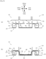
Figure 1] Figure 1 shows views illustrating formed products. - [
Figure 2] Figure 2 is a view illustrating an example of a formed product produced by using a press forming apparatus according to a first embodiment. - [
Figure 3] Figure 3 is a schematic view illustrating a press forming apparatus according to the first embodiment. - [
Figure 4] Figure 4 is a schematic view illustrating a positional relationship among a punch, a die, and a pad. - [
Figure 5] Figure 5 is a view illustrating a blank used as a starting material in a production method according to the first embodiment. - [
Figure 6] Figure 6 shows views for describing the production method according to the first embodiment. - [
Figure 7] Figure 7 illustrates another example of the press forming apparatus. - [
Figure 8] Figure 8 is a schematic view illustrating a further example of the press forming apparatus. - [
Figure 9] Figure 9 is a schematic view illustrating a further example of the press forming apparatus. - [
Figure 10] Figure 10 shows schematic views illustrating another example of the production method for a formed product. - [
Figure 11] Figure 11 is a schematic view illustrating another example of a formed product. - [
Figure 12] Figure 12 shows views for describing a production method for the formed product ofFigure 11 . - [
Figure 13] Figure 13 shows schematic views illustrating a further example of the press forming apparatus. - [
Figure 14] Figure 14 shows schematic views illustrating a further example of the press forming apparatus. - [
Figure 15] Figure 15 shows views illustrating a further example of the production method for a formed product. - [
Figure 16] Figure 16 shows schematic views illustrating a further example of the press forming apparatus. - [
Figure 17] Figure 17 shows schematic views illustrating a further example of the press forming apparatus. - [
Figure 18] Figure 18 is a schematic view illustrating a further example of a formed product. - [
Figure 19] Figure 19 shows schematic views illustrating a further example of the press forming apparatus. - [
Figure 20] Figure 20 is a schematic view illustrating a further example of the press forming apparatus. - [
Figure 21] Figure 21 is a schematic view illustrating a further example of the press forming apparatus. - [
Figure 22] Figure 22 shows schematic views illustrating a further example of the press forming apparatus. - [
Figure 23] Figure 23 shows schematic views illustrating a further example of the press forming apparatus. - [
Figure 24] Figure 24 is a schematic view illustrating further examples of formed products. - [
Figure 25] Figure 25 is a schematic view illustrating a further example of a formed product. - [
Figure 26] Figure 26 is a view illustrating a blank used as a starting material in a production method according to a second embodiment. - [
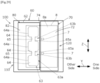
Figure 27] Figure 27 shows schematic views illustrating a press forming apparatus according to the second embodiment. - [
Figure 28] Figure 28 is a schematic view illustrating a further example of the press forming apparatus. - [
Figure 29] Figure 29 is a schematic view illustrating a further example of the press forming apparatus. - A press forming apparatus and a production method for a formed product according to embodiments of the present invention will now be described with reference to drawings.
- First, a formed product produced by using a press forming apparatus according to a first embodiment of the present invention will be briefly described.
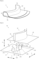
Figure 2 is a view illustrating an example of a formed product produced by using the press forming apparatus according to the first embodiment of the present invention. - As illustrated in
Figure 2 , a formedproduct 3 has a closed sectional shape. In the embodiment, the formedproduct 3 includes plate-like flange portions vertical wall portions top plate portion 3e. Theflange portions top plate portion 3e each have a flat plate shape. - In the embodiment, the
flange portion 3b is overlaid on theflange portion 3a such that the formedproduct 3 has a closed sectional shape. Thevertical wall portion 3c is provided to extend upward in a bent manner from an edge of theflange portion 3a. Thevertical wall portion 3d is provided to extend upward in a bent manner from an edge of theflange portion 3b on theflange portion 3a. Thetop plate portion 3e is provided to connect an upper edge of thevertical wall portion 3c with an upper edge of thevertical wall portion 3d. - In the embodiment, the
vertical wall portions top plate portion 3e are curved in an arc shape when viewed from above (when viewed from the thickness direction of thetop plate portion 3e). In theflange portion 3a, four through-holes 5 (seeFigure 5 ) for insertingsupport portions 24 described later (seeFigure 3 ) are formed in a portion that faces thetop plate portion 3e. -
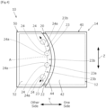
Figure 3 is a schematic view illustrating a press forming apparatus according to the first embodiment of the present invention. More specifically,Figure 3 illustrates a press forming apparatus that can produce the formedproduct 3 illustrated inFigure 2 . - Here, in
Figure 3 , when a blank is subjected to press forming, a direction in which a first die set (punch) or a second die set (die) moves is indicated by an arrow X (hereinafter, denoted as a "press direction X"), and the width direction of the press forming apparatus is indicated by an arrow Y (hereinafter, denoted as a "width direction Y"). The width direction Y is a direction perpendicular to the press direction X. Furthermore, a direction that intersects the press direction X and the width direction Y is indicated by an arrow Z (hereinafter, denoted as an "intersecting direction Z"). In the embodiment, the intersecting direction Z is a direction perpendicular to the press direction X and the width direction Y. - Although detailed description will be omitted, materials as in well-known dies can be used to produce each component of the press forming apparatus. Each component of the press forming apparatus can be driven by drive mechanisms as in well-known press machines (electric cylinder, hydraulic cylinder, gas cushion apparatus).
- As illustrated in
Figure 3 , apress forming apparatus 10 according to the embodiment includes a first die set 12 provided on one side in the press direction X and a second die set 14 provided on the other side in the press direction X. That is, the first die set 12 and the second die set 14 are provided in positions to face each other in the press direction X. The first die set 12 and the second die set 14 perform relative movement in the press direction X. In the embodiment, the first die set 12 includes apunch 20, and the second die set 14 includes adie 40 and apad 50. -
Figure 4 is a schematic view illustrating a positional relationship among thepunch 20, thedie 40, and thepad 50. Here,Figure 4 is a view of thepress forming apparatus 10 viewed from above. As illustrated inFigure 3 andFigure 4 , thepunch 20 includes afirst support surface 22 and apunch portion 23 that protrudes from thefirst support surface 22. In the embodiment, thefirst support surface 22 faces the other side (second die set 14 side) in the press direction X. Thepunch portion 23 protrudes from thefirst support surface 22 toward the other side in the press direction X. When viewed from the second die set 14 side in the press direction X, thepunch portion 23 faces awall surface 44 of the die 40, which will be described later. In the embodiment, thepunch portion 23 includes a plurality ofsupport portions 24 that protrude from thefirst support surface 22 toward the other side in the press direction X. Thesupport portion 24 may be referred to as a protruding portion. - The
support portions 24 are spaced apart from each other and provided to be aligned in a curved shape when viewed from the second die set 14 side in the press direction X. In the embodiment, eachsupport portion 24 is formed in a circular column shape to have aside surface 24a of a circular section. Note that the shape of thesupport portion 24 illustrated inFigure 1 is only one example and the shape of thesupport portion 24 is not limited to the above example. As illustrated inFigure 6 described later, although it is preferable that the top portion of eachsupport portion 24 has a flat shape, it may have a spherical crown shape. - In the embodiment, the
side surface 23a of thepunch portion 23 is constituted of a plurality ofside surfaces 24a of the plurality ofsupport portions 24. When viewed from the second die set 14 side in the press direction X, theside surface 23a of thepunch portion 23 includes anopening 23b opened on thewall surface 44 side of the die 40, which will be described later. In the embodiment, theside surface 23a of thepunch portion 23 includes a plurality ofopenings 23b. In the embodiment, the side surfaces 24a of twoadjacent support portions 24 are arranged so as to be spaced apart with theopening 23b in between. In other words, twoadjacent support portions 24 are arranged so as to be spaced apart with theopening 23b in between. Here, in the embodiment, theopening 23b is also opened on the second die set 14 side in the press direction X. Furthermore, in the embodiment, theopening 23b is formed to pass through between twoadjacent support portions 24 in the width direction Y. - The
first support surface 22 extends on both sides of at least eachsupport portion 24 in the intersecting direction Z. As illustrated inFigure 4 , in the embodiment, thefirst support surface 22 extends at least between thesupport portions 24 and on both sides of the plurality ofsupport portions 24 in an arrangement direction A of the plurality ofsupport portions 24. Note that, in the present specification, the arrangement direction A refers to a direction along a line (a curve in the example ofFigure 4 ) obtained by connecting the centers of thesupport portions 24 when viewed from the second die set 14 side (above) in the press direction X. - As illustrated in
Figures 3 and4 , thedie 40 includes apress surface 42 and awall surface 44 that is continuous with thepress surface 42. In the embodiment, thepress surface 42 faces the one side (first die set 12 side) in the press direction X. Thewall surface 44 extends from an edge of thepress surface 42 to the other side (opposite to the first die set 12) in the press direction X. Thepress surface 42 is provided on one side of the punch portion 23 (the plurality of support portions 24) in the width direction Y. In the embodiment, thepress surface 42 is disposed so as to be out of position from a position to face thepunch portion 23 in the press direction X. Thewall surface 44 is positioned between the punch portion 23 (the plurality of support portions 24) and thepress surface 42 in the width direction Y. - The
press surface 42 and thewall surface 44 are provided, with respect to eachsupport portion 24, to extend from the one side to the other side of thesupport portion 24 in the intersecting direction Z. In the embodiment, as illustrated inFigure 4 , thepress surface 42 and thewall surface 44 are provided to extend along the arrangement direction A and from one side to the other side of the plurality ofsupport portions 24 in the arrangement direction A. Furthermore, in the embodiment, when viewed from the first die set 12 side in the press direction X, thewall surface 44 is curved in an arc shape to protrude toward the one side in the width direction Y. - Referring to
Figure 3 , in the press direction X, thedie 40 is provided to be capable of approaching and withdrawing relative to thefirst support surface 22 of thepunch 20. That is, thepress surface 42 and thewall surface 44 are capable of approaching and withdrawing relative to thefirst support surface 22 in the press direction X. - As illustrated in
Figures 3 and4 , thepad 50 is disposed in a position to face the punch portion 23 (the plurality of support portions 24) in the press direction X. In the embodiment, thepad 50 includes asecond support surface 52 that faces the punch portion 23 (the plurality of support portions 24) in the press direction X. Thesecond support surface 52 is provided, with respect to eachsupport portion 24, to extend from the one side to the other side of thesupport portions 24 in the intersecting direction Z. In the embodiment, as illustrated inFigure 4 , thesecond support surface 52 is provided to extend from the one side to the other side of the plurality ofsupport portions 24 in the arrangement direction A. - Referring to
Figure 3 , in the press direction X, thepad 50 is provided to be capable of approaching and withdrawing relative to the punch portion 23 (the plurality of support portions 24) of thepunch 20. That is, thesecond support surface 52 is capable of approaching and withdrawing relative to the plurality ofsupport portions 24 in the press direction X. - Next, a production method for a formed product will be described. In the production method according to the embodiment, a pre-processed blank is subjected to press forming by using the
press forming apparatus 10 described above to produce the formedproduct 3. The following is a specific description. -
Figure 5 is a view illustrating a blank used as a starting material in the production method according to the embodiment. As illustrated inFigure 5 , a blank 4 includes a first plate-like portion 4a, a second plate-like portion 4b, and a third plate-like portion 4c. - The first plate-
like portion 4a has a flat plate shape. A plurality of through-holes 5 is formed in the first plate-like portion 4a. In the embodiment, the plurality of through-holes 5 is provided such that they correspond to the plurality of support portions 24 (seeFigure 3 ) of the first die set 12 (seeFigure 3 ). Here, the through-hole 5 is not limited to circular in shape and may be formed in any size and shape to the extent that thesupport portion 24 can be inserted. Accordingly, the through-hole 5 may have any other shape such as an elliptic shape or a polygonal shape. The relationship between the through-hole 5 and thesupport portion 24 will be described later. - The second plate-
like portion 4b has a flat plate shape and is provided to face the first plate-like portion 4a in the thickness direction of the first plate-like portion 4a. Furthermore, the second plate-like portion 4b is provided so as to be spaced apart from the first plate-like portion 4a in the thickness direction of the first plate-like portion 4a. The third plate-like portion 4c is provided to extend in the thickness direction of the first plate-like portion 4a so as to connect an edge of the first plate-like portion 4a with an edge of the second plate-like portion 4b. In the embodiment, the third plate-like portion 4c is a portion corresponding to thevertical wall portion 3c (seeFigure 2 ) of the formed product 3 (seeFigure 2 ) and is curved in an arc shape when viewed from the thickness direction of the first plate-like portion 4a. - Although the material and the dimensions of the blank 4 are not particularly limited, for example, a sheet material (for example, steel sheet) that has a tensile strength of 270 MPa or more and a thickness of 0.5 to 5 mm can be used to produce the blank 4. Although the production method for the blank 4 is not particularly limited, it is possible to produce the blank 4, for example, by using a well-known press forming apparatus to subject a plate material with a plurality of through-
holes 5 formed therein to press forming. -
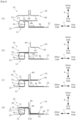
Figure 6 shows views for describing the production method according to the embodiment. Here, inFigure 6 , components of thepress forming apparatus 10 and the blank 4 are simplified. Furthermore,Figure 6 illustrates thepress forming apparatus 10 and the blank 4 as viewed from the intersecting direction Z. - When the blank 4 is subjected to press forming, as illustrated in
Figure 6 (a) , the blank 4 is first placed on thefirst support surface 22 of the first die set 12 such that the punch portion 23 (the plurality of support portions 24) crosses the first plate-like portion 4a from first die set 12 side in the press direction X and supports the second plate-like portion 4b. More specifically, the first plate-like portion 4a is supported by thefirst support surface 22 such that the third plate-like portion 4c is located on the other side of the punch portion 23 (the plurality of support portions 24) in the width direction Y and thesupport portions 24 of thepunch portion 23 protrude through the through-holes 5 toward the second plate-like portion 4b side with respect to the first plate-like portion 4a. - Next, as illustrated in
Figure 6 (b) , the pad 50 (second support surface 52) is moved to the one side (first die set 12 side) in the press direction X, so that the second plate-like portion 4b is clamped between the punch portion 23 (the plurality of support portions 24) and thesecond support surface 52. Note that, in the embodiment, the state illustrated inFigure 6 (b) corresponds to the state of "supporting the first plate-like portion by the first support surface from the side of the first die set and supporting the second plate-like portion by the punch portion crossing the first plate-like portion in the press direction from the side of the first die set". - Next, as illustrated in the views (b), (c), and (d) of
Figure 6 , the die 40 (press surface 42) is moved from the other side (second die set 14 side) to the one side (first die set 12 side) in the press direction X relative to the top portion of the punch portion 23 (the plurality of support portions 24). Consequently, a portion of the second plate-like portion 4b on the one side with respect to the punch portion 23 (the plurality of support portions 24) in the width direction Y is pressed to the one side (first die set 12 side) in the press direction X. As a result, the second plate-like portion 4b is subjected to bending deformation and the formedproduct 3 is completed. In the embodiment, at a forming bottom dead center of the relative movement between the first die set 12 and the second die set 14 in the press direction X (the state illustrated inFigure 6 (d) ), thewall surface 44 of the die 40 faces theside surface 23a of thepunch portion 23 with part of the second plate-like portion 4b in between. Furthermore, at the forming bottom dead center, thewall surface 44 of the die 40 faces at least oneopening 23b in the width direction Y. In the embodiment, at the forming bottom dead center, thewall surface 44 faces the plurality ofopenings 23b in the width direction Y. - Finally, the second die set 14 (die 40 and pad 50) is moved to the other side in the press direction X, and the formed
product 3 is taken out from thepress forming apparatus 10. - As described above, according to the
press forming apparatus 10 according to the embodiment, when the formedproduct 3, which includes a plate-like portion (flange portion 3a) facing thetop plate portion 3e, is to be produced from the blank 4, the portion to be thetop plate portion 3e in the second plate-like portion 4b of the blank 4 can be supported by the punch portion 23 (support portions 24) from the first plate-like portion 4a side. This makes it possible to shape thevertical wall portion 3d and theflange portion 3b by simple bending with thepress surface 42 and thewall surface 44 of the second die set 14. In this case, it is not necessary to use a core to produce the formedproduct 3, and it is possible to avoid an increase in the number of processes. As a result, it is possible to efficiently produce the formedproduct 3. - Here, when the formed
product 3 produced as described above is to be used as a structural member for automobile, the through-hole 5 may be utilized as a drainage hole or may be closed by a patch or the like. Furthermore, to secure sufficient rigidity of surrounding portions of the through-hole 5, the portion at which the through-hole 5 is formed may be subjected to burring, a patch or the like for stiffening may be applied to peripheral edge portions of the through-hole 5, or the wall thickness may be increased in the peripheral edge portions of the through-hole 5. - The shape of the formed
product 3 is not limited to the above example. For example, thevertical wall portions top plate portion 3e may be curved such that they protrude in the opposite direction to thevertical wall portions top plate portion 3e illustrated inFigure 2 when viewed from the thickness direction of thetop plate portion 3e. In this case, the shape of any portion of thepress forming apparatus 10 may be altered in any way depending on the shape of the formedproduct 3. Specifically, for example, as illustrated inFigure 7 , when viewed from the second die set 14 side in the press direction X, the plurality ofsupport portions 24 is arranged such that they exhibit a curve that protrudes toward the other side in the width direction Y, and thewall surface 44 is provided to protrude toward the other side in the width direction Y. - Furthermore, the
vertical wall portions top plate portion 3e may also be formed to extend in a linear shape when viewed from the thickness direction of thetop plate portion 3e. In this case, although not illustrated, for example, when viewed from the second die set 14 side in the press direction X, the plurality ofsupport portions 24 is arranged such that they are aligned in a linear shape along the intersecting direction Z, and thewall surface 44 is provided to extend in parallel along the intersecting direction Z. - Furthermore, one of the
vertical wall portions top plate portion 3e. Still in this case, the plurality ofsupport portions 24 may be arranged depending on the shape of thevertical wall portions - Note that the distance between
adjacent support portions 24, the arrangement of the plurality ofsupport portions 24, the number ofsupport portions 24, and the shape and the dimensions of thesupport portion 24 are not limited to the above example and may be altered in any way depending on the shape, the dimensions, and the like of the formed product to be produced. For example, as illustrated inFigure 8 , the plurality ofsupport portions 24 may be provided to align in the width direction Y. Furthermore, as illustrated inFigure 9 , thepunch portion 23 of the first die set 12 may be constituted of onesupport portion 24. In this case, only one through-hole may be formed in the first plate-like portion 4a of the blank 4 (seeFigure 5 ) for inserting onesupport portion 24. - Although in the above-described embodiment, description has been made to the case of producing the formed
product 3 that includes theflange portion 3b (seeFigure 2 ), as illustrated inFigure 10 , a formedproduct 3 with noflange portion 3b may be produced. The same applies to embodiments described later. Here, inFigure 10 , the view (a) illustrates thepress forming apparatus 10 in a state in which the second plate-like portion 4b of the blank 4 is clamped by the punch portion 23 (support portions 24) and thesecond support surface 52, the view (b) illustrates thepress forming apparatus 10 in a state in which a portion of the second plate-like portion 4b on the one side with respect to the punch portion 23 (support portions 24) in the width direction Y is pressed to the one side (first die set 12 side) in the press direction X by thepress surface 42, and the view (c) illustrates thepress forming apparatus 10 when the formedproduct 3 is to be taken out (during release). - Furthermore, while in the above-described embodiment, part of the
flange portion 3a and part of theflange portion 3b are overlaid on each other such that the formedproduct 3 has a closed sectional shape, the formedproduct 3 may not have a closed sectional shape. For example, a clearance may be formed between theflange portion 3a and theflange portion 3b (vertical wall portion 3d) in a direction in parallel to the width direction of thetop plate portion 3e as the formedproduct 3 illustrated inFigure 11 . Here, the formedproduct 3 illustrated inFigure 11 can be produced as described below, for example. -
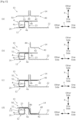
Figure 12 shows views for describing a production method for the formedproduct 3 ofFigure 11 . When the formedproduct 3 inFigure 11 is to be produced, as illustrated inFigure 12 (a) , the blank 4 is placed on thefirst support surface 22 of the first die set 12 as in the case of producing the formedproduct 3 inFigure 2 . However, the length in the width direction Y of the first plate-like portion 4a (seeFigure 12 ) of the blank 4 (seeFigure 12 ) used when the formedproduct 3 inFigure 11 is to be produced is shorter than the length in the width direction Y of the first plate-like portion 4a (seeFigure 6 ) of the blank 4 (seeFigure 6 ) used when the formedproduct 3 inFigure 2 is to be produced. Furthermore, any through-hole 5 (seeFigure 5 ) may not be formed in the first plate-like portion 4a of the blank 4 (seeFigure 12 ) used when the formedproduct 3 inFigure 11 is to be produced. - In the embodiment, the first plate-
like portion 4a is supported by thefirst support surface 22 such that third plate-like portion 4c is located on the other side of the punch portion 23 (the plurality of support portions 24) in the width direction Y and the plurality ofsupport portions 24 protrudes toward the second plate-like portion 4b side with respect to the first plate-like portion 4a on the one side of the first plate-like portion 4a in the width direction Y. - Next, as illustrated in
Figure 12 (b) , the pad 50 (second support surface 52) is moved to the one side (first die set 12 side) in the press direction X, so that the second plate-like portion 4b is clamped between the punch portion 23 (the plurality of support portions 24) and thesecond support surface 52. Note that, in the embodiment, the state illustrated inFigure 12 (b) corresponds to the state of "supporting the first plate-like portion by the first support surface from the side of the first die set and supporting the second plate-like portion by the punch portion crossing the first plate-like portion in the press direction from the side of the first die set". - Next, as illustrated in the views (b), (c), and (d) of
Figure 12 , the die 40 (press surface 42) is moved from the other side (second die set 14 side) to the one side (first die set 12 side) in the press direction X relative to the top portion of the punch portion 23 (the plurality of support portions 24). Consequently, a portion of the second plate-like portion 4b on the one side with respect to the plurality ofsupport portions 24 in the width direction Y is pressed to the one side (first die set 12 side) in the press direction X, and the formedproduct 3 illustrated inFigure 11 is completed. - Although in the above-described embodiment, description has been made to the case in which the
first support surface 22 of the first die set 12 has a flat shape, the shape of the first die set 12 is not limited to the above example.Figure 13 shows schematic views illustrating another example of thepress forming apparatus 10. InFigure 13 , the view (a) illustrates the blank 4 and thepress forming apparatus 10 before shaping, and the view (b) illustrates the blank 4 (formed product 3) and thepress forming apparatus 10 after shaping. - The difference of the
press forming apparatus 10 illustrated inFigure 13 from thepress forming apparatus 10 illustrated inFigure 3 is the shape of the first die set 12 (punch 20). The difference of the first die set 12 illustrated inFigure 13 from the first die set 12 illustrated inFigure 3 is the shape of thefirst support surface 22. Specifically, thefirst support surface 22 of the first die set 12 illustrated inFigure 13 includes aflat surface 22a, avertical surface 22b extending from the edge on the one side in the width direction Y of theflat surface 22a to the second die set 14 side, and aflat surface 22c extending from the edge on the second die set 14 side in the press direction X of thevertical surface 22b to the one side in the width direction Y. The punch portion 23 (support portions 24) is provided to protrude toward from theflat surface 22a to the second die set 14 side. - In this case, as illustrated in
Figure 13 , the blank 4 that includes the first plate-like portion 4a of a bent shape to correspond to thefirst support surface 22 may be used. In this way, it is possible to produce formedproducts 3 that have various sectional shapes by altering the shape of thefirst support surface 22 and the shape of the blank 4 as necessary. In the example illustrated inFigure 13 , the formedproduct 3 is produced, which includes aflange portion 30a, anvertical wall portion 30b, abottom plate portion 30c, anvertical wall portion 30d, atop plate portion 30e, anvertical wall portion 30f, and aflange portion 30g formed by thepress forming apparatus 10. - In the description below, a tubular portion formed in the formed
product 3 by the press forming apparatus will be referred to as a shaped portion. In the formedproduct 3 illustrated inFigure 13 , the shapedportion 30 is formed to protrude fromflange portions flange portion 30a (30g). - Although detailed description will be omitted, it is possible to produce formed
products 3 of various sectional shapes by altering the shapes of other components of thepress forming apparatus 10 as necessary. For example, in thepress forming apparatus 10 illustrated inFigure 14 (a) , thesupport portion 24 of thepunch portion 23 includes atop surface 240 that is inclined with respect to the press direction X and thesecond support surface 52 of thepad 50 includes aninclined surface 520 that is substantially parallel to thetop surface 240 of thesupport portion 24. Furthermore, in thepress forming apparatus 10 illustrated inFigure 14 (b) , thefirst support surface 22 further includes asupport surface 22d that is inclined with respect to the press direction X. Thesupport portion 24 of thepunch portion 23 is provided to protrude from thesupport surface 22d toward the second die set 14 side. In these cases, it is possible to produce formedproducts 3 depending on the shapes of thefirst support surface 22 and thesupport portion 24 by usingblanks 4 depending on the shapes of thefirst support surface 22, thesupport portion 24, and thesecond support surface 52. - In the above-described embodiment, description has been made to the case of producing the formed
product 3 from the blank 4 that includes the first plate-like portion 4a, the second plate-like portion 4b, and the third plate-like portion 4c, the shape of the blank 4 is not limited to the above example. For example, as illustrated inFigure 15 (a) , the blank 4 may include a fourth plate-like portion 4d and a fifth plate-like portion 4e in addition to the first plate-like portion 4a, the second plate-like portion 4b, and the third plate-like portion 4c. Here, the fourth plate-like portion 4d and the fifth plate-like portion 4e are provided on the opposite side to the second plate-like portion 4b and the third plate-like portion 4c in the thickness direction of the first plate-like portion 4a. In the embodiment, through-holes 5 are formed in a portion of the first plate-like portion 4a that faces the second plate-like portion 4b and in a portion that faces the fourth plate-like portion 4d, respectively. - In the embodiment, as illustrated in
Figure 15 (b) , in a way similar to those described inFigure 6 , the second plate-like portion 4b is subjected to press forming by thepress forming apparatus 10 to form theflange portion 3b, thevertical wall portion 3d, and thetop plate portion 3e. In the formedproduct 3 illustrated inFigure 15 , a shapedportion 32 is constituted of theflange portion 3b, thevertical wall portions top plate portion 3e. - Next, as illustrated in the views (c) and (d) of
Figure 15 , the blank 4 is rotated by 180 degrees when viewed from the intersecting direction Z (seeFigure 3 ), and the fourth plate-like portion 4d is subjected to press forming by thepress forming apparatus 10. In this way, a shapedportion 34 constituted of aflange portion 3f,vertical wall portions product 3 that includes a pair of shapedportions like portion 4a. Note that the shapedportion 32 may not include theflange portion 3b or the shapedportion 34 may not include theflange portion 3f. -
Figure 16 shows views illustrating another modification of the press forming apparatus. The difference of thepress forming apparatus 10 illustrated inFigure 16 from thepress forming apparatus 10 illustrated inFigure 6 is as follows. - As illustrated in
Figure 16 , in the embodiment, thedie 40 includes wall surfaces 44 on both sides in the width direction Y. Furthermore, therespective pads 50 are provided on the one side and the other side in the width direction Y of thedie 40. The punch portion 23 (one or more support portions 24) is provided in a portion on the first die set 12 (punch 20) that faces eachsecond support surface 52 of the die 40 in the press direction X. - The blank 4 utilized in the embodiment includes a pair of second plate-
like portions 4b and a pair of third plate-like portions 4c. One or more through-holes 5 for inserting one ormore support portions 24 are formed in the respective portions in the first plate-like portion 4a that face the pair of second plate-like portions 4b. - Still in the embodiment, as in the above-described embodiment, when the blank 4 is subjected to press forming, as illustrated in
Figure 16 (a) , the first plate-like portion 4a is supported by thefirst support surface 22 such that the punch portion 23 (support portions 24) protrudes toward the second plate-like portion 4b side through the through-hole 5 with respect to the first plate-like portion 4a. Next, as illustrated inFigure 16 (b) , each pad 50 (second support surface 52) is moved to the one side (first die set 12 side) in the press direction X, so that each of the pair of second plate-like portions 4b is clamped between the punch portion 23 (support portions 24) and thesecond support surface 52 of eachpad 50. - Next, the die 40 (press surface 42) is moved from the other side (second die set 14 side) in the press direction X to the one side (first die set 12 side) relative to the top portion of the punch portion 23 (support portions 24). Consequently, a portion on the die 40 side of each second plate-
like portion 4b from the punch portion 23 (support portions 24) in the width direction Y is pressed to the one side (first die set 12 side) in the press direction X. In this way, the formedproduct 3 that includes the pair of shapedportions 32 is completed. - Although detailed description will be omitted, as illustrated in
Figure 17 , a pair of dies 40 may be provided to be located between a pair ofpads 50 in the width direction Y. In this case, as in the production method described inFigure 16 , it is possible to produce the formedproduct 3 that includes the pair of shapedportions 32 by operating the dies 40 and thepads 50. Note that, in thepress forming apparatus 10 illustrated inFigure 17 , the pair of shapedportions 32 may be formed at the same time by operating the pair of dies 40 at the same time or the pair of shapedportions 32 may be formed sequentially by operating the pair of dies 40 sequentially. - Furthermore, although detailed description will be omitted, in the
press forming apparatus 10 illustrated inFigures 16 and17 , it is possible to produce the formedproduct 3 that includes a pair of shapedportions 30 as illustrated inFigure 18 by altering the shape of thefirst support surface 22 as in thepress forming apparatus 10 inFigure 13 . - Although in the above-described embodiment, description has been made to the case in which the first die set 12 is constituted of the
punch 20, the configuration of the first die set 12 is not limited to the above example.Figure 19 shows views illustrating another modification of thepress forming apparatus 10. The difference of thepress forming apparatus 10 illustrated inFigure 19 from thepress forming apparatus 10 illustrated inFigure 6 is that the first die set 12 includes thepunch 20 and adie 26. - Still in the embodiment, the
punch 20 includes thefirst support surface 22 and the punch portion 23 (one or more support portions 24) as in the above-describedpunch 20. However, in the embodiment, as illustrated inFigure 19 , thedie 26 is provided in a portion that faces thepress surface 42 of the die 40 in the press direction X, with no first support surface 22 (punch 20) being provided. - As illustrated in
Figure 19 , thedie 26 includes apress surface 26a facing the other side (second die set 14 side) in the press direction X and awall surface 26b extending from an edge of thepress surface 26a to the one side (opposite to second die set 14) in the press direction X. Thepress surface 26a is provided on the one side of punch portion 23 (one or more support portions 24) in the width direction Y to face thepress surface 42 in the press direction X. Thewall surface 26b is positioned between the punch portion 23 (one or more support portions 24) and thepress surface 26a in the width direction Y. - As in the
press surface 42 and thewall surface 44, thepress surface 26a and thewall surface 26b are provided, with respect to eachsupport portion 24, to extend from the one side to the other side of thesupport portions 24 in the intersecting direction Z (seeFigure 3 ). In the press direction X, thedie 26 is provided to be capable of approaching and withdrawing relative to thefirst support surface 22 of thepunch 20. - When the blank 4 is subjected to press forming in the embodiment, as illustrated in
Figure 19 (a) , the blank 4 is first placed on thefirst support surface 22 and thepress surface 26a. More specifically, the first plate-like portion 4a is supported by thefirst support surface 22 and thepress surface 26a such that the punch portion 23 (one or more support portions 24) protrudes toward the second plate-like portion 4b side with respect to the first plate-like portion 4a through one or more through-holes 5. - Next, as illustrated in
Figure 19 (b) , thepad 50 is moved so that the second plate-like portion 4b is clamped between the punch portion 23 (one or more support portions 24) and thesecond support surface 52. Next, thedie 26 and the die 40 are moved in the press direction X to approach each other. Consequently, portions in the first plate-like portion 4a and the second plate-like portion 4b on the one side with respect to the punch portion 23 (one or more support portions 24) in the width direction Y are pressed to approach each other in the press direction X. As a result, the formedproduct 3 that includes the shapedportion 30 is completed. - Although in the above-described embodiment, description has been made to the case of the punch portion 23 (support portions 24) being provided on the first die set 12, the second die set 14 may be provided with a punch portion (support portion) that has a configuration similar to that of the
punch portion 23.Figure 20 is a view illustrating a further example of thepress forming apparatus 10. Here,Figure 20 is a schematic view of thepunch 20 and thepad 50 of thepress forming apparatus 10 and the blank 4 as viewed from the other side in the width direction Y. - The difference of the
press forming apparatus 10 illustrated inFigure 20 from thepress forming apparatus 10 illustrated inFigure 6 is that thepad 50 includes apunch portion 53 that protrudes from thesecond support surface 52. Thepunch portion 53 protrudes from thesecond support surface 52 toward the one side (first die set 12 side) in the press direction X. In the embodiment, thepunch portion 53 includes a plurality ofsupport portions 54 that protrudes from thesecond support surface 52 toward the one side in the press direction X. In the embodiment, the plurality ofsupport portions 24 and the plurality ofsupport portions 54 are disposed to be aligned alternately along the intersecting direction Z. - When the blank 4 is subjected to press forming by using the
press forming apparatus 10 illustrated inFigure 20 , it is possible to perform press forming on the second plate-like portion 4b while the second plate-like portion 4b is clamped between the punch portion 23 (the plurality of support portions 24) and thesecond support surface 52 and the first plate-like portion 4a is clamped between the punch portion 53 (the plurality of support portions 54) and thefirst support surface 22. This makes it possible to satisfactorily prevent the blank 4 from moving during press forming, so that more accurate press forming is made possible. - Although in the above-described embodiment, the
first support surface 22 and the punch portion 23 (support portion 24) are provided integrally to thepunch 20, thefirst support surface 22 and the punch portion 23 (support portion 24) may be provided as separate members. The same applies to a second embodiment described later. Furthermore, although in the above-described embodiment, thesecond support surface 52 and the punch portion 53 (support portion 54) are provided integrally to thepad 50, thesecond support surface 52 and the punch portion 53 (support portion 54) may be provided as different members.Figure 21 is a view illustrating a further example of thepress forming apparatus 10. Here,Figure 21 is a schematic view of thepunch 20 and thepad 50 of thepress forming apparatus 10 and the blank 4 as viewed from the other side in the width direction Y. - The difference of the
press forming apparatus 10 illustrated inFigure 21 from thepress forming apparatus 10 illustrated inFigure 20 is that thepunch 20 includes abase portion 20a provided as a separate member and the punch portion 23 (the plurality of support portions 24) and that thepad 50 includes abase portion 50a provided as a separate member and the punch portion 53 (the plurality of support portions 54). - In the
press forming apparatus 10 according to the embodiment, thefirst support surface 22 is provided on thebase portion 20a. The punch portion 23 (the plurality of support portions 24) is provided such that it can be moved with respect to thefirst support surface 22 in the press direction X. In addition, thesecond support surface 52 is provided on thebase portion 50a. The punch portion 53 (the plurality of support portions 54) is provided to be movable in the press direction X with respect to thesecond support surface 52. In the embodiment, eachsupport portion 24 and eachsupport portion 54 are supported to be movable in the press direction X with respect to thebase portions - Still in the
press forming apparatus 10 according to the embodiment, as in thepress forming apparatus 10 illustrated inFigure 20 , it is possible to perform press forming on the second plate-like portion 4b while the second plate-like portion 4b is clamped between the punch portion 23 (the plurality of support portions 24) and thesecond support surface 52 and the first plate-like portion 4a is clamped between the punch portion 53 (the plurality of support portions 54) and thefirst support surface 22. This makes it possible to satisfactorily prevent the blank 4 from moving during press forming, so that more accurate press forming is made possible. - Although in the above-described embodiment, description has been made to the case in which the
first support surface 22 is flat in a section of thepunch 20 perpendicular to the width direction Y, the shape of thefirst support surface 22 is not limited to the above example. The same applies to thesecond support surface 52. Specifically, as illustrated in the views (a) to (c) ofFigure 22 , the shapes of thefirst support surface 22 and thesecond support surface 52 may be altered as necessary depending on the shape of the blank 4 (formed product 3). In addition, the height of each support portion 24 (position of the tip portion) may be altered as necessary depending on the shape of the blank 4 (formed product 3). Accordingly, in the press direction X, the position of the top portion of at least one of thesupport portions 24 may be different from the positions of top portions ofother support portions 24. - Although in the above-described embodiment, description has been made to the case in which the second die set 14 includes the
die 40 and thepad 50, the configuration of the second die set 14 is not limited to the above example. For example, in place of thedie 40 and thepad 50 of thepress forming apparatus 10 illustrated inFigure 6 , thedie 40a may be provided as illustrated inFigure 23 . Here, thedie 40a includes apress surface 42a, awall surface 44a, and asecond support surface 52a, which have configurations similar to those of thepress surface 42, thewall surface 44, and thesecond support surface 52 in the above-described embodiment. - Referring to the views (a) and (b) of
Figure 23 , in the embodiment, when the blank 4 is subjected to press forming, thedie 40a is relatively moved to thepunch 20 side in the press direction X. Consequently, thepress surface 42a, thewall surface 44a, and thesecond support surface 52a come into contact with the second plate-like portion 4b sequentially, subjecting the second plate-like portion 4b to press forming. In this way, the formedproduct 3 that includes the shapedportion 32 is completed. - Although detailed description will be omitted, the second die set may not include the second support surface. Accordingly, for example, in the second die set 14 illustrated in
Figure 6 , nopad 50 may be provided. In this case, it is also possible to perform press forming on the blank 4 by thepunch 20 and thedie 40. - Although detailed description will be omitted, in the
press forming apparatus 10 described above, it is possible to obtain formed products of various shapes as illustrated inFigure 24 by adjusting the shape and dimensions of any portion as necessary. -
Figure 25 is a view illustrating an example of a formed product produced by utilizing a press forming apparatus according to the second embodiment of the present invention. - As illustrated in
Figure 25 , a formedproduct 6 includes a plate-like flange portion 6a, a plate-likevertical wall portion 6b, and a plate-like flange portion 6c. Thevertical wall portion 6b is provided to connect an edge of the flange portion 6a with an edge of the flange portion 6c. The flange portion 6a and the flange portion 6c are provided to extend from thevertical wall portion 6b in the opposite direction to each other in the thickness direction of thevertical wall portion 6b. - A plurality of protruding
portions 7 is formed on thevertical wall portion 6b. The protrudingportions 7 are formed to protrude from thevertical wall portion 6b toward the flange portion 6a side in the thickness direction of thevertical wall portion 6b. Note that the protrudingportions 7 may also be referred to as recessed portions because they are viewed as recessed portions from outside. - In the embodiment, the formed
product 6 is produced by using a blank in which the plurality of protrudingportions 7 is formed in advance as a starting material.Figure 26 is a view illustrating an example of the blank used as a starting material in the embodiment. As illustrated inFigure 26 , the blank 8 includes a plate-like portion 8a and the plurality of protrudingportions 7 protruding from the plate-like portion 8a in a thickness direction of the plate-like portion 8a. Although bottomed protrudingportions 7 are formed in the embodiment, for example, protrudingportions 7, which include a hole passing through in the thickness direction of thevertical wall portion 6b, may be formed by burring or the like. -
Figure 27 shows schematic views illustrating a press forming apparatus according to the second embodiment of the present invention: the view (a) is a view of the press forming apparatus as viewed from the intersecting direction Z, and the view (b) is a view of the press forming apparatus as viewed from above. Still in the embodiment, as in the above-described embodiment, the direction in which the first die set or the second die set move when a blank is subjected to press forming is denoted as the press direction X. The width direction Y of the press forming apparatus is the direction perpendicular to the press direction X. The direction that intersects the press direction X and the width direction Y is denoted as the intersecting direction Z. - As illustrated in
Figure 27 , apress forming apparatus 100 according to the embodiment includes a first die set 110 provided on the one side in the press direction X and a second die set 120 provided on the other side in the press direction X. That is, the first die set 110 and the second die set 120 are provided in positions to face in the press direction X. The first die set 110 and the second die set 120 perform relative movement in the press direction X. In the embodiment, the first die set 110 includes apunch 60 and the second die set 120 includes adie 70 and apad 80. - The
punch 60 includes afirst support surface 62 and apunch portion 63 that protrudes from thefirst support surface 62. In the embodiment, thefirst support surface 62 faces the other side (second die set 120 side) in the press direction X. Thepunch portion 63 protrudes from thefirst support surface 62 toward the other side in the press direction X. When viewed from the second die set 120 side in the press direction X, thepunch portion 63 faces awall surface 74 of the die 70, which will be described later. In the embodiment, thepunch portion 63 includes a plurality ofsupport portions 64 that protrude from thefirst support surface 62 toward the other side in the press direction X. The plurality ofsupport portions 64 are spaced apart from each other and provided to be aligned along the intersecting direction Z. In the embodiment, eachsupport portion 64 is formed in a columnar shape to haveside surfaces 64a of a rectangular section. Note that the shape of thesupport portion 64 illustrated inFigure 27 is only one example and the shape of thesupport portion 64 is not limited to the above example. Although it is preferable that the top portion of eachsupport portion 64 has a flat shape, it may have a spherical crown shape. - In the embodiment, the
side surface 63a of thepunch portion 63 is constituted of a plurality ofside surfaces 64a of the plurality ofsupport portions 64. When viewed from the second die set 120 side in the press direction X, theside surface 63a of thepunch portion 63 includes anopening 63b opened on thewall surface 74 side of the die 70, which will be described later. In the embodiment, theside surface 63a of thepunch portion 63 includes a plurality ofopenings 63b. In the embodiment, the side surfaces 64a of twoadjacent support portions 64 are arranged so as to be spaced apart with theopening 63b in between. In other words, twoadjacent support portions 64 are arranged so as to be spaced apart with theopening 63b in between. Here, in the embodiment, theopening 63b is also opened on the second die set 120 side in the press direction X. Furthermore, in the embodiment, theopening 63b is formed to pass through between twoadjacent support portions 64 in the width direction Y. - As in the
first support surface 22 of the first embodiment, thefirst support surface 62 extends at least on both sides of eachsupport portion 64 in the intersecting direction Z. In the embodiment, as in thefirst support surface 22 of the first embodiment, thefirst support surface 62 extends at least between thesupport portions 64 and on both sides of the plurality ofsupport portions 64 in the arrangement direction of the plurality ofsupport portions 64. - As in the above-described
die 40, thedie 70 includes apress surface 72 and awall surface 74 that is continuous with thepress surface 72. In the embodiment, thepress surface 72 faces the one side (first die set 110 side) in the press direction X. Thewall surface 74 extends from an edge of thepress surface 72 to the other side in the press direction X. Thepress surface 72 is provided on the one side of the punch portion 63 (the plurality of support portions 64) in the width direction Y. In the embodiment, thepress surface 72 is disposed so as to be out of position from a position to face thepunch portion 63 in the press direction X. Thewall surface 74 is positioned between the punch portion 63 (the plurality of support portions 64) and thepress surface 72 in the width direction Y. - As in the
press surface 42 and thewall surface 44 described abovbe, thepress surface 72 and thewall surface 74 are provided, with respect to eachsupport portion 64, to extend from the one side to the other side of thesupport portion 64 in the intersecting direction Z. In the embodiment, thepress surface 72 and thewall surface 74 is provided along the arrangement direction of the plurality ofsupport portions 64 and extend from the one side to the other side of the plurality ofsupport portions 64 in the arrangement direction. In the press direction X, thedie 70 is provided to be capable of approaching and withdrawing relative to thefirst support surface 62 of thepunch 60. - As in the above-described
pad 50, thepad 80 is disposed in a position to face the punch portion 63 (the plurality of support portions 64) in the press direction X. In the embodiment, thepad 80 includes asecond support surface 82 that faces the punch portion 63 (the plurality of support portions 64) in the press direction X. As in the above-describedsecond support surface 52, thesecond support surface 82 is provided, with respect to eachsupport portion 64, to extend from the one side to the other side of thesupport portion 64 in the intersecting direction Z. In the embodiment, thesecond support surface 82 is provided to extend from the one side to the other side of the plurality ofsupport portions 64 in the arrangement direction of the plurality ofsupport portions 64. In the press direction X, thepad 80 is provided to be capable of approaching and withdrawing relative to the plurality ofsupport portions 64 of thepunch 60. - When the blank 8 is subjected to press forming, the blank 8 is first supported by the punch portion 63 (the plurality of support portions 64). More specifically, the blank 8 is supported by the plurality of
support portions 64 such that each protrudingportion 7 is in the state of being located on the one side of the plurality ofsupport portions 64 in the width direction Y, being located between twoadjacent support portions 64 in the intersecting direction Z, and protruding toward the one side in the press direction X. - Next, as in the first embodiment, the pad 80 (second support surface 82) is moved to the one side in the press direction X, so that the plate-
like portion 8a is clamped between the punch portion 63 (the plurality of support portions 64) and thesecond support surface 82. Thereafter, as in the first embodiment, the die 70 (press surface 72) is moved from the other side to the one side in the press direction X relative to the top portion of the punch portion 63 (the plurality of support portions 64). Consequently, a portion of the plate-like portion 8a on the one side with respect to the plurality ofsupport portions 64 in the width direction Y is pressed to the one side in the press direction X. As a result, the plate-like portion 8a is subjected to bending deformation and the formedproduct 6 is completed. In the embodiment, at a forming bottom dead center of the relative movement between the first die set 110 and the second die set 120 in the press direction X, thewall surface 74 of the die 70 faces theside surface 63a of thepunch portion 63 with part of the plate-like portion 8a in between, and each protrudingportion 7 enters theopening 63b without contacting theside surface 63a. Note that the state of thepress forming apparatus 100 at the forming bottom dead center of the relative movement between the first die set 110 and the second die set 120 corresponds to the state in which thepunch 20 is replaced with thepunch 60, thedie 40 is replaced with the die 70, and thepad 50 is replaced with thepad 80 inFigure 6 (d) . - As described above, according to the
press forming apparatus 100 according to the embodiment, when the formedproduct 6 with the protrudingportions 7 formed in thevertical wall portion 6b is to be produced from the blank 8, the protrudingportions 7 formed in the blank 8 in advance can be disposed betweenadjacent support portions 64 in the intersecting direction Z. In this way, when the blank 8 is subjected to press forming, it is possible to prevent the protrudingportions 7 from contacting thefirst die set 110. As a result, it is possible to efficiently produce the formedproduct 6. - Note that, as in the plurality of
support portions 24 in the above-described embodiment, the height (position of a top portion) of the plurality ofsupport portions 64 may be altered as necessary depending on the shape and the dimensions of the formedproduct 6. Accordingly, positions of top portions of the plurality ofsupport portions 64 in the press direction X may be different from each other. Although detailed description will be omitted, as in the above-described embodiment, the shapes and the dimensions of other portions of thepress forming apparatus 100 may be altered as necessary depending on the shape and the dimensions of the formedproduct 6. Furthermore, although detailed description will be omitted, the flange portion 6c may not be formed. The same applies to embodiments described later and flange portion may not be formed. - Although in the above-described embodiment, description has been made to the case in which the second die set 120 includes one
die 70, the configuration of the second die set 120 is not limited to the above example. For example, as in thepress forming apparatus 100 illustrated inFigure 28 , the dies 70 may be provided on both sides of thepad 80 in the width direction Y. In this case, for example, as illustrated inFigure 28 , the blank 8 is disposed such that the respective plurality of protrudingportions 7 is positioned on either side of the punch portion 63 (the plurality of support portions 64) in the width direction Y and each protrudingportion 7 is located between twoadjacent support portions 64 in the intersecting direction Z, and the blank 8 is subjected to press forming. In this way, it is possible to produce hat-shaped formed products as illustrated inFigure 1 (c) , while each protrudingportion 7 is prevented from contacting the first die set 110 during press forming. Although detailed description will be omitted, thepad 80 may not be provided in thepress forming apparatus 100 illustrated inFigure 28 . In this case, it is also possible to produce hat-shaped formed products while each protrudingportion 7 is prevented from contacting the first die set 110 during press forming. - Although in the above-described embodiment, description has been made to the case in which the
punch portion 63 of the first die set 110 is configured such thatadjacent support portions 64 are spaced apart with theopening 63b in between, the configuration of the punch portion of the first die set 110 is not limited to the above example. For example, as illustrated inFigure 29 , thepunch portion 63 of the first die set 110 may further include a connectingportion 65 that connectsadjacent support portions 64. - Referring to
Figure 29 , in the embodiment, the connectingportion 65 is provided in theopening 63b. In other words, in the embodiment, eachopening 63b includes the connectingportion 65. As in thesupport portion 64, each connectingportion 65 is provided to protrude from thefirst support surface 62 in the press direction X. In the embodiment, theside surface 63a of thepunch portion 63 is constituted of the plurality ofside surfaces 64a of the plurality ofsupport portions 64 and the plurality ofside surfaces 65a of the plurality of connectingportions 65. Still in the embodiment, the plurality ofsupport portions 64 of thepunch portion 63 protrudes from thefirst support surface 62 toward the other side in the press direction X. The plurality ofsupport portions 64 is provided such that they are spaced apart from each other and aligned along the intersecting direction Z. When viewed from the second die set 120 side in the press direction X (seeFigure 27 ), the distance between theside surface 65a of the connectingportion 65 and thewall surface 74 of the die 70 is larger than the distance between theside surface 64a of thesupport portion 64 and thewall surface 74. That is, in the width direction Y, the space between the connectingportion 65 and thewall surface 74 is larger than the space between thesupport portion 64 and thewall surface 74. In the embodiment, in the press direction X, the top portion of thesupport portion 64 is located on the other side (second die set 120 side) from the top portion of the connectingportion 65. - When the blank 8 is subjected to press forming, the blank 8 is first supported by the plurality of
support portions 64 of thepunch portion 63. More specifically, the blank 8 is supported by the plurality ofsupport portions 64 such that each protrudingportion 7 is in the state of being located on the one side of the plurality ofsupport portions 64 in the width direction Y, being located between twoadjacent support portions 64 in the intersecting direction Z, and protruding toward the one side (first die set 110 side) in the press direction X. - Next, as in the above-described embodiment, the pad 80 (second support surface 82) is moved to the one side in the press direction X, so that the plate-
like portion 8a is clamped between the plurality ofsupport portions 64 and thesecond support surface 82. Thereafter, the die 70 (press surface 72) is moved from the other side (second die set 120 side) to the one side (first die set 110 side) in the press direction X relative to the top portions of the plurality ofsupport portions 64. Consequently, a portion of the plate-like portion 8a on the one side with respect to the plurality ofsupport portions 64 in the width direction Y is pressed to the one side in the press direction X. As a result, the plate-like portion 8a is subjected to bending deformation and the formedproduct 6 is completed. Still in the embodiment, at a forming bottom dead center of the relative movement between the first die set 110 and the second die set 120 in the press direction X, thewall surface 74 of the die 70 faces theside surface 63a of thepunch portion 63 with part of the plate-like portion 8a in between, and each protrudingportion 7 enters theopening 63b without contacting theside surface 63a. - Still in the embodiment, when the formed
product 6 is to be produced from the blank 8, the protrudingportions 7 formed in the blank 8 in advance can be disposed betweenadjacent support portions 64 in the intersecting direction Z. In this way, when the blank 8 is subjected to press forming, it is possible to prevent the protrudingportions 7 from contacting thefirst die set 110. As a result, it is possible to efficiently produce the formedproduct 6. - Note that, as in the above-described embodiment, the height of the plurality of support portions 64 (position of a top portion) may be altered as necessary depending on the shape and the dimensions of the formed
product 6. Accordingly, positions of top portions of the plurality ofsupport portions 64 in the press direction X may be different from each other. Positions of top portions of the plurality of connectingportions 65 in the press direction X may also be different from each other. Furthermore, in the press direction X, the position of a top portion of at least one of thesupport portions 64 may be different from the position of a top portion of the connectingportion 65 that is adjacent to thesupport portion 64, and positions of top portions of the plurality ofsupport portions 64 and positions of top portions of the plurality of connectingportion 65 may be equal to each other. - Although not illustrated, also in the
press forming apparatus 100 including the plurality of connectingportions 65, as in thepress forming apparatus 100 illustrated inFigure 28 , the dies 70 may be provided on both sides of thepad 80. In this way, it is possible to produce hat-shaped formed products as illustrated inFigure 1 (c) , while each protrudingportion 7 is prevented from contacting the first die set 110 during press forming. Although detailed description will be omitted, as in thepress forming apparatus 100 illustrated inFigure 28 , thepad 80 may not be provided when two dies 70 is provided. - According to the present invention, it is possible to efficiently produce a formed product that includes a flange portion facing a top plate portion and a formed product with a protruding portion formed in an vertical wall portion.
-
- 3, 6 formed product
- 4, 8 blank
- 5 through-hole
- 7 protruding portion
- 10, 100 press forming apparatus
- 12, 110 first die set
- 14, 120 second die set
- 20, 60 punch
- 22, 62 first support surface
- 24, 64 support portion
- 40, 70 die
- 42, 72 press surface
- 44, 74 wall surface
- 50, 80 pad
- 52, 82 second support surface
Claims (9)
- A press forming apparatus comprisinga first die set and a second die set in positions to face each other in a press direction, the first die set and the second die set performing relative movement in the press direction,the first die set including a first support surface and a punch portion that protrudes from the first support surface, andthe second die set including a press surface disposed so as to be out of position from a position to face the punch portion in the press direction and a wall surface that is continuous with the press surface, whereinwhen viewed from a side of the second die set in the press direction, the punch portion includes a side surface that faces the wall surface and that includes an opening opened on a side of the wall surface, andat a forming bottom dead center of the relative movement between the first die set and the second die set in the press direction, the wall surface faces the side surface of the punch portion.
- The press forming apparatus according to claim 1, whereinthe punch portion includes a plurality of support portions,the side surface of the punch portion includes side surfaces of the plurality of support portions, andthe side surfaces of two adjacent support portions among the plurality of support portions are arranged so as to be spaced apart with the opening in between.
- The press forming apparatus according to claim 2, whereinthe opening includes a connecting portion that connects two adjacent support portions among the plurality of support portions, andwhen viewed from the side of the second die set in the press direction, a distance between a side surface of the connecting portion and the wall surface is longer than a distance between the side surface of the support portion and the wall surface.
- The press forming apparatus according to claim 2 or 3, whereinthe opening includes a connecting portion that connects two adjacent support portions among the plurality of support portions, andin the press direction, a position of a top portion of at least one of the support portions is different from a position of a top portion of the connecting portion that is adjacent to the support portion.
- The press forming apparatus according to any one of claims 2 to 4, wherein
in the press direction, a position of a top portion of at least one support portion among the plurality of support portions is different from positions of top portions of other support portions. - The press forming apparatus according to any one of claims 1 to 5, wherein
the second die set includes a pad disposed in a position to face the punch portion in the press direction. - A production method for a formed product by a first die set and a second die set facing across a blank in a press direction performing relative movement in the press direction to subject the blank to press forming, whereinthe first die set includes a first support surface and a punch portion that protrudes from the first support surface,the second die set includes a press surface disposed so as to be out of position from a position to face the punch portion in the press direction and a wall surface that is continuous with the press surface, andthe blank includes a first plate-like portion and a second plate-like portion that faces the first plate-like portion in the press direction,the method comprising:supporting the first plate-like portion by the first support surface from a side of the first die set and supporting the second plate-like portion by the punch portion crossing the first plate-like portion in the press direction from the side of the first die set; and in this state,subjecting the second plate-like portion to bending deformation by the press surface that moves relative to the punch portion in the press direction, whereinat a forming bottom dead center of the relative movement between the first die set and the second die set in the press direction, the wall surface faces a side surface of the punch portion with part of the second plate-like portion in between.
- The production method for a formed product according to claim 7, wherein
when the second plate-like portion is supported by the punch portion, the punch portion passes through a through-hole formed in the first plate-like portion to cross the first plate-like portion. - A production method for a formed product by a first die set and a second die set facing across a blank in a press direction performing relative movement in the press direction to subject the blank to press forming, whereinthe first die set includes a first support surface and a punch portion that protrudes from the first support surface,the second die set includes a press surface disposed so as to be out of position from a position to face the punch portion in the press direction and a wall surface that is continuous with the press surface,when viewed from a side of the second die set in the press direction, the punch portion includes a side surface that faces the wall surface and that includes an opening opened on a side of the wall surface, andthe blank includes a plate-like portion and a protruding portion that protrudes from the plate-like portion in a thickness direction of the plate-like portion,the method comprising:supporting the plate-like portion by the punch portion in the press direction from a side of the first die set; and in this state,subjecting the plate-like portion to bending deformation by the press surface that moves relative to the punch portion in the press direction, whereinat a forming bottom dead center of the relative movement between the first die set and the second die set in the press direction, the wall surface faces a side surface of the punch portion with part of the plate-like portion in between, and the protruding portion enters the opening without contacting the side surface.
Applications Claiming Priority (2)
| Application Number | Priority Date | Filing Date | Title |
|---|---|---|---|
| JP2022091684 | 2022-06-06 | ||
| PCT/JP2023/021045 WO2023238872A1 (en) | 2022-06-06 | 2023-06-06 | Pressing device and method for manufacturing pressed product |
Publications (2)
| Publication Number | Publication Date |
|---|---|
| EP4537952A1 true EP4537952A1 (en) | 2025-04-16 |
| EP4537952A4 EP4537952A4 (en) | 2025-07-02 |
Family
ID=89118346
Family Applications (1)
| Application Number | Title | Priority Date | Filing Date |
|---|---|---|---|
| EP23819852.7A Pending EP4537952A4 (en) | 2022-06-06 | 2023-06-06 | Pressing device and method for producing a pressed product |
Country Status (7)
| Country | Link |
|---|---|
| US (1) | US20250332630A1 (en) |
| EP (1) | EP4537952A4 (en) |
| JP (1) | JP7364994B1 (en) |
| KR (1) | KR20250020601A (en) |
| CN (1) | CN119325411A (en) |
| MX (1) | MX2024014785A (en) |
| WO (1) | WO2023238872A1 (en) |
Families Citing this family (2)
| Publication number | Priority date | Publication date | Assignee | Title |
|---|---|---|---|---|
| MX2022011063A (en) * | 2020-03-26 | 2022-09-21 | Nippon Steel Corp | Mold. |
| CN115362038A (en) * | 2020-04-03 | 2022-11-18 | 日本制铁株式会社 | Hot press device and method for manufacturing hot press molded article |
Family Cites Families (8)
| Publication number | Priority date | Publication date | Assignee | Title |
|---|---|---|---|---|
| JP3613702B2 (en) * | 1999-09-21 | 2005-01-26 | トヨタ自動車株式会社 | STRUCTURAL MEMBER HAVING CLOSED SECTION, ITS MANUFACTURING DEVICE, AND ITS MANUFACTURING METHOD |
| JP2008120227A (en) | 2006-11-10 | 2008-05-29 | Aisin Seiki Co Ltd | Method for manufacturing shock absorber for vehicle |
| JP5470812B2 (en) * | 2008-11-20 | 2014-04-16 | 日産自動車株式会社 | Method and apparatus for manufacturing a press-molded product, and press-molded product |
| JP5783339B2 (en) * | 2012-12-19 | 2015-09-24 | 新日鐵住金株式会社 | PRESS MOLD AND METHOD FOR PRODUCING PRESS MOLDED PRODUCT |
| ES2728702T3 (en) * | 2013-01-07 | 2019-10-28 | Nippon Steel Corp | Method and device for manufacturing an L-shaped component |
| DE102015108768A1 (en) * | 2015-06-03 | 2016-12-08 | Thyssenkrupp Ag | Method and apparatus for obtaining large collar lengths |
| JP6849160B1 (en) * | 2019-07-04 | 2021-03-24 | 日本製鉄株式会社 | Manufacturing method and manufacturing equipment for structural members |
| JP2021053651A (en) * | 2019-09-27 | 2021-04-08 | 株式会社神戸製鋼所 | Press molding method and device |
-
2023
- 2023-06-06 CN CN202380044339.9A patent/CN119325411A/en active Pending
- 2023-06-06 US US18/868,652 patent/US20250332630A1/en active Pending
- 2023-06-06 EP EP23819852.7A patent/EP4537952A4/en active Pending
- 2023-06-06 KR KR1020257000174A patent/KR20250020601A/en active Pending
- 2023-06-06 WO PCT/JP2023/021045 patent/WO2023238872A1/en not_active Ceased
- 2023-06-06 JP JP2023548721A patent/JP7364994B1/en active Active
-
2024
- 2024-11-28 MX MX2024014785A patent/MX2024014785A/en unknown
Also Published As
| Publication number | Publication date |
|---|---|
| KR20250020601A (en) | 2025-02-11 |
| JPWO2023238872A1 (en) | 2023-12-14 |
| CN119325411A (en) | 2025-01-17 |
| US20250332630A1 (en) | 2025-10-30 |
| WO2023238872A1 (en) | 2023-12-14 |
| MX2024014785A (en) | 2025-01-09 |
| JP7364994B1 (en) | 2023-10-19 |
| EP4537952A4 (en) | 2025-07-02 |
Similar Documents
| Publication | Publication Date | Title |
|---|---|---|
| JP5835768B2 (en) | Manufacturing method of frame parts | |
| KR101932878B1 (en) | Press forming apparatus and press forming method | |
| JP5390152B2 (en) | Closed structure member manufacturing method, press forming apparatus, and closed structure member | |
| US20250332630A1 (en) | Press forming apparatus and production method for formed product | |
| EP3524367B1 (en) | Method and device for manufacturing press formed article | |
| US20180078993A1 (en) | Method of forming a closed cross-sectional structure | |
| US9630238B2 (en) | Method and apparatus that forms a closed cross-sectional structure | |
| US6591576B1 (en) | Structural member having closed sections, and apparatus and method for producing the structural member | |
| CN114260349B (en) | Manufacturing method of compressed molded articles and molding die | |
| CN112313020A (en) | Method for manufacturing press-formed article | |
| EP4035789A1 (en) | Method for manufacturing press-formed article, press-formed article, and press-forming device | |
| CN116422774A (en) | A stamping die and forming process for a longitudinal beam | |
| KR100957407B1 (en) | Starting cam mold for vehicles | |
| CN105689551A (en) | Integral display back plate punching mold | |
| WO2023189155A1 (en) | Rectangular can manufacturing method and rectangular can manufacturing device | |
| CN118555991A (en) | Press molding device and method for manufacturing press molded product | |
| JP2001246424A (en) | Press forming apparatus and press forming method | |
| JPH0415375Y2 (en) | ||
| CN219520098U (en) | Bending device | |
| JP2002248529A (en) | Body panel press device | |
| JP2000202527A (en) | Closing method and apparatus | |
| JPH0328970Y2 (en) | ||
| JPH0341917Y2 (en) | ||
| JPH0647135B2 (en) | Method for manufacturing metal products having arcuate portions at corners | |
| JP2002248523A (en) | How to press body panels |
Legal Events
| Date | Code | Title | Description |
|---|---|---|---|
| STAA | Information on the status of an ep patent application or granted ep patent |
Free format text: STATUS: THE INTERNATIONAL PUBLICATION HAS BEEN MADE |
|
| PUAI | Public reference made under article 153(3) epc to a published international application that has entered the european phase |
Free format text: ORIGINAL CODE: 0009012 |
|
| STAA | Information on the status of an ep patent application or granted ep patent |
Free format text: STATUS: REQUEST FOR EXAMINATION WAS MADE |
|
| 17P | Request for examination filed |
Effective date: 20241212 |
|
| AK | Designated contracting states |
Kind code of ref document: A1 Designated state(s): AL AT BE BG CH CY CZ DE DK EE ES FI FR GB GR HR HU IE IS IT LI LT LU LV MC ME MK MT NL NO PL PT RO RS SE SI SK SM TR |
|
| REG | Reference to a national code |
Ref country code: DE Ref legal event code: R079 Free format text: PREVIOUS MAIN CLASS: B21D0024000000 Ipc: B21D0005060000 |
|
| A4 | Supplementary search report drawn up and despatched |
Effective date: 20250604 |
|
| RIC1 | Information provided on ipc code assigned before grant |
Ipc: B21D 22/02 20060101ALN20250528BHEP Ipc: B21D 22/26 20060101ALN20250528BHEP Ipc: B21D 5/01 20060101ALI20250528BHEP Ipc: B21D 53/88 20060101ALI20250528BHEP Ipc: B21D 5/06 20060101AFI20250528BHEP |
|
| DAV | Request for validation of the european patent (deleted) | ||
| DAX | Request for extension of the european patent (deleted) |