EP4537875A2 - Medikamentenabgabevorrichtung mit nadelträger - Google Patents
Medikamentenabgabevorrichtung mit nadelträger Download PDFInfo
- Publication number
- EP4537875A2 EP4537875A2 EP25160216.5A EP25160216A EP4537875A2 EP 4537875 A2 EP4537875 A2 EP 4537875A2 EP 25160216 A EP25160216 A EP 25160216A EP 4537875 A2 EP4537875 A2 EP 4537875A2
- Authority
- EP
- European Patent Office
- Prior art keywords
- needle
- carrier
- drug
- hub
- trigger
- Prior art date
- Legal status (The legal status is an assumption and is not a legal conclusion. Google has not performed a legal analysis and makes no representation as to the accuracy of the status listed.)
- Pending
Links
Images














Classifications
-
- A—HUMAN NECESSITIES
- A61—MEDICAL OR VETERINARY SCIENCE; HYGIENE
- A61M—DEVICES FOR INTRODUCING MEDIA INTO, OR ONTO, THE BODY; DEVICES FOR TRANSDUCING BODY MEDIA OR FOR TAKING MEDIA FROM THE BODY; DEVICES FOR PRODUCING OR ENDING SLEEP OR STUPOR
- A61M5/00—Devices for bringing media into the body in a subcutaneous, intra-vascular or intramuscular way; Accessories therefor, e.g. filling or cleaning devices, arm-rests
- A61M5/178—Syringes
- A61M5/24—Ampoule syringes, i.e. syringes with needle for use in combination with replaceable ampoules or carpules, e.g. automatic
- A61M5/2422—Ampoule syringes, i.e. syringes with needle for use in combination with replaceable ampoules or carpules, e.g. automatic using emptying means to expel or eject media, e.g. pistons, deformation of the ampoule, or telescoping of the ampoule
- A61M5/2429—Ampoule syringes, i.e. syringes with needle for use in combination with replaceable ampoules or carpules, e.g. automatic using emptying means to expel or eject media, e.g. pistons, deformation of the ampoule, or telescoping of the ampoule by telescoping of ampoules or carpules with the syringe body
-
- A—HUMAN NECESSITIES
- A61—MEDICAL OR VETERINARY SCIENCE; HYGIENE
- A61M—DEVICES FOR INTRODUCING MEDIA INTO, OR ONTO, THE BODY; DEVICES FOR TRANSDUCING BODY MEDIA OR FOR TAKING MEDIA FROM THE BODY; DEVICES FOR PRODUCING OR ENDING SLEEP OR STUPOR
- A61M5/00—Devices for bringing media into the body in a subcutaneous, intra-vascular or intramuscular way; Accessories therefor, e.g. filling or cleaning devices, arm-rests
- A61M5/178—Syringes
- A61M5/20—Automatic syringes, e.g. with automatically actuated piston rod, with automatic needle injection, filling automatically
-
- A—HUMAN NECESSITIES
- A61—MEDICAL OR VETERINARY SCIENCE; HYGIENE
- A61M—DEVICES FOR INTRODUCING MEDIA INTO, OR ONTO, THE BODY; DEVICES FOR TRANSDUCING BODY MEDIA OR FOR TAKING MEDIA FROM THE BODY; DEVICES FOR PRODUCING OR ENDING SLEEP OR STUPOR
- A61M5/00—Devices for bringing media into the body in a subcutaneous, intra-vascular or intramuscular way; Accessories therefor, e.g. filling or cleaning devices, arm-rests
- A61M5/178—Syringes
- A61M5/20—Automatic syringes, e.g. with automatically actuated piston rod, with automatic needle injection, filling automatically
- A61M5/2033—Spring-loaded one-shot injectors with or without automatic needle insertion
-
- A—HUMAN NECESSITIES
- A61—MEDICAL OR VETERINARY SCIENCE; HYGIENE
- A61M—DEVICES FOR INTRODUCING MEDIA INTO, OR ONTO, THE BODY; DEVICES FOR TRANSDUCING BODY MEDIA OR FOR TAKING MEDIA FROM THE BODY; DEVICES FOR PRODUCING OR ENDING SLEEP OR STUPOR
- A61M5/00—Devices for bringing media into the body in a subcutaneous, intra-vascular or intramuscular way; Accessories therefor, e.g. filling or cleaning devices, arm-rests
- A61M5/178—Syringes
- A61M5/28—Syringe ampoules or carpules, i.e. ampoules or carpules provided with a needle
- A61M5/281—Syringe ampoules or carpules, i.e. ampoules or carpules provided with a needle using emptying means to expel or eject media, e.g. pistons, deformation of the ampoule, or telescoping of the ampoule
-
- A—HUMAN NECESSITIES
- A61—MEDICAL OR VETERINARY SCIENCE; HYGIENE
- A61M—DEVICES FOR INTRODUCING MEDIA INTO, OR ONTO, THE BODY; DEVICES FOR TRANSDUCING BODY MEDIA OR FOR TAKING MEDIA FROM THE BODY; DEVICES FOR PRODUCING OR ENDING SLEEP OR STUPOR
- A61M5/00—Devices for bringing media into the body in a subcutaneous, intra-vascular or intramuscular way; Accessories therefor, e.g. filling or cleaning devices, arm-rests
- A61M5/178—Syringes
- A61M5/31—Details
- A61M5/315—Pistons; Piston-rods; Guiding, blocking or restricting the movement of the rod or piston; Appliances on the rod for facilitating dosing ; Dosing mechanisms
- A61M5/31511—Piston or piston-rod constructions, e.g. connection of piston with piston-rod
-
- A—HUMAN NECESSITIES
- A61—MEDICAL OR VETERINARY SCIENCE; HYGIENE
- A61M—DEVICES FOR INTRODUCING MEDIA INTO, OR ONTO, THE BODY; DEVICES FOR TRANSDUCING BODY MEDIA OR FOR TAKING MEDIA FROM THE BODY; DEVICES FOR PRODUCING OR ENDING SLEEP OR STUPOR
- A61M5/00—Devices for bringing media into the body in a subcutaneous, intra-vascular or intramuscular way; Accessories therefor, e.g. filling or cleaning devices, arm-rests
- A61M5/178—Syringes
- A61M5/31—Details
- A61M5/32—Needles; Details of needles pertaining to their connection with syringe or hub; Accessories for bringing the needle into, or holding the needle on, the body; Devices for protection of needles
- A61M5/3293—Needles; Details of needles pertaining to their connection with syringe or hub; Accessories for bringing the needle into, or holding the needle on, the body; Devices for protection of needles characterised by features of the needle hub
-
- A—HUMAN NECESSITIES
- A61—MEDICAL OR VETERINARY SCIENCE; HYGIENE
- A61M—DEVICES FOR INTRODUCING MEDIA INTO, OR ONTO, THE BODY; DEVICES FOR TRANSDUCING BODY MEDIA OR FOR TAKING MEDIA FROM THE BODY; DEVICES FOR PRODUCING OR ENDING SLEEP OR STUPOR
- A61M5/00—Devices for bringing media into the body in a subcutaneous, intra-vascular or intramuscular way; Accessories therefor, e.g. filling or cleaning devices, arm-rests
- A61M5/178—Syringes
- A61M5/31—Details
- A61M5/32—Needles; Details of needles pertaining to their connection with syringe or hub; Accessories for bringing the needle into, or holding the needle on, the body; Devices for protection of needles
- A61M5/34—Constructions for connecting the needle, e.g. to syringe nozzle or needle hub
- A61M5/348—Constructions for connecting the needle, e.g. to syringe nozzle or needle hub snap lock, i.e. upon axial displacement of needle assembly
-
- A—HUMAN NECESSITIES
- A61—MEDICAL OR VETERINARY SCIENCE; HYGIENE
- A61M—DEVICES FOR INTRODUCING MEDIA INTO, OR ONTO, THE BODY; DEVICES FOR TRANSDUCING BODY MEDIA OR FOR TAKING MEDIA FROM THE BODY; DEVICES FOR PRODUCING OR ENDING SLEEP OR STUPOR
- A61M5/00—Devices for bringing media into the body in a subcutaneous, intra-vascular or intramuscular way; Accessories therefor, e.g. filling or cleaning devices, arm-rests
- A61M5/178—Syringes
- A61M5/20—Automatic syringes, e.g. with automatically actuated piston rod, with automatic needle injection, filling automatically
- A61M2005/206—With automatic needle insertion
-
- A—HUMAN NECESSITIES
- A61—MEDICAL OR VETERINARY SCIENCE; HYGIENE
- A61M—DEVICES FOR INTRODUCING MEDIA INTO, OR ONTO, THE BODY; DEVICES FOR TRANSDUCING BODY MEDIA OR FOR TAKING MEDIA FROM THE BODY; DEVICES FOR PRODUCING OR ENDING SLEEP OR STUPOR
- A61M5/00—Devices for bringing media into the body in a subcutaneous, intra-vascular or intramuscular way; Accessories therefor, e.g. filling or cleaning devices, arm-rests
- A61M5/178—Syringes
- A61M5/24—Ampoule syringes, i.e. syringes with needle for use in combination with replaceable ampoules or carpules, e.g. automatic
- A61M5/2455—Ampoule syringes, i.e. syringes with needle for use in combination with replaceable ampoules or carpules, e.g. automatic with sealing means to be broken or opened
- A61M5/2466—Ampoule syringes, i.e. syringes with needle for use in combination with replaceable ampoules or carpules, e.g. automatic with sealing means to be broken or opened by piercing without internal pressure increase
- A61M2005/2474—Ampoule syringes, i.e. syringes with needle for use in combination with replaceable ampoules or carpules, e.g. automatic with sealing means to be broken or opened by piercing without internal pressure increase with movable piercing means, e.g. ampoule remains fixed or steady
-
- A—HUMAN NECESSITIES
- A61—MEDICAL OR VETERINARY SCIENCE; HYGIENE
- A61M—DEVICES FOR INTRODUCING MEDIA INTO, OR ONTO, THE BODY; DEVICES FOR TRANSDUCING BODY MEDIA OR FOR TAKING MEDIA FROM THE BODY; DEVICES FOR PRODUCING OR ENDING SLEEP OR STUPOR
- A61M5/00—Devices for bringing media into the body in a subcutaneous, intra-vascular or intramuscular way; Accessories therefor, e.g. filling or cleaning devices, arm-rests
- A61M5/178—Syringes
- A61M5/31—Details
- A61M5/32—Needles; Details of needles pertaining to their connection with syringe or hub; Accessories for bringing the needle into, or holding the needle on, the body; Devices for protection of needles
- A61M5/3205—Apparatus for removing or disposing of used needles or syringes, e.g. containers; Means for protection against accidental injuries from used needles
- A61M2005/3206—Needle or needle hub disconnecting devices forming part of or being attached to the hub or syringe body
-
- A—HUMAN NECESSITIES
- A61—MEDICAL OR VETERINARY SCIENCE; HYGIENE
- A61M—DEVICES FOR INTRODUCING MEDIA INTO, OR ONTO, THE BODY; DEVICES FOR TRANSDUCING BODY MEDIA OR FOR TAKING MEDIA FROM THE BODY; DEVICES FOR PRODUCING OR ENDING SLEEP OR STUPOR
- A61M5/00—Devices for bringing media into the body in a subcutaneous, intra-vascular or intramuscular way; Accessories therefor, e.g. filling or cleaning devices, arm-rests
- A61M5/178—Syringes
- A61M5/31—Details
- A61M5/32—Needles; Details of needles pertaining to their connection with syringe or hub; Accessories for bringing the needle into, or holding the needle on, the body; Devices for protection of needles
- A61M5/3205—Apparatus for removing or disposing of used needles or syringes, e.g. containers; Means for protection against accidental injuries from used needles
- A61M5/321—Means for protection against accidental injuries by used needles
- A61M5/3243—Means for protection against accidental injuries by used needles being axially-extensible, e.g. protective sleeves coaxially slidable on the syringe barrel
- A61M5/326—Fully automatic sleeve extension, i.e. in which triggering of the sleeve does not require a deliberate action by the user
- A61M2005/3267—Biased sleeves where the needle is uncovered by insertion of the needle into a patient's body
-
- A—HUMAN NECESSITIES
- A61—MEDICAL OR VETERINARY SCIENCE; HYGIENE
- A61M—DEVICES FOR INTRODUCING MEDIA INTO, OR ONTO, THE BODY; DEVICES FOR TRANSDUCING BODY MEDIA OR FOR TAKING MEDIA FROM THE BODY; DEVICES FOR PRODUCING OR ENDING SLEEP OR STUPOR
- A61M2202/00—Special media to be introduced, removed or treated
- A61M2202/0007—Special media to be introduced, removed or treated introduced into the body
-
- A—HUMAN NECESSITIES
- A61—MEDICAL OR VETERINARY SCIENCE; HYGIENE
- A61M—DEVICES FOR INTRODUCING MEDIA INTO, OR ONTO, THE BODY; DEVICES FOR TRANSDUCING BODY MEDIA OR FOR TAKING MEDIA FROM THE BODY; DEVICES FOR PRODUCING OR ENDING SLEEP OR STUPOR
- A61M5/00—Devices for bringing media into the body in a subcutaneous, intra-vascular or intramuscular way; Accessories therefor, e.g. filling or cleaning devices, arm-rests
- A61M5/178—Syringes
- A61M5/31—Details
- A61M5/32—Needles; Details of needles pertaining to their connection with syringe or hub; Accessories for bringing the needle into, or holding the needle on, the body; Devices for protection of needles
- A61M5/3202—Devices for protection of the needle before use, e.g. caps
-
- A—HUMAN NECESSITIES
- A61—MEDICAL OR VETERINARY SCIENCE; HYGIENE
- A61M—DEVICES FOR INTRODUCING MEDIA INTO, OR ONTO, THE BODY; DEVICES FOR TRANSDUCING BODY MEDIA OR FOR TAKING MEDIA FROM THE BODY; DEVICES FOR PRODUCING OR ENDING SLEEP OR STUPOR
- A61M5/00—Devices for bringing media into the body in a subcutaneous, intra-vascular or intramuscular way; Accessories therefor, e.g. filling or cleaning devices, arm-rests
- A61M5/178—Syringes
- A61M5/31—Details
- A61M5/32—Needles; Details of needles pertaining to their connection with syringe or hub; Accessories for bringing the needle into, or holding the needle on, the body; Devices for protection of needles
- A61M5/3205—Apparatus for removing or disposing of used needles or syringes, e.g. containers; Means for protection against accidental injuries from used needles
- A61M5/321—Means for protection against accidental injuries by used needles
- A61M5/3243—Means for protection against accidental injuries by used needles being axially-extensible, e.g. protective sleeves coaxially slidable on the syringe barrel
- A61M5/3275—Means for protection against accidental injuries by used needles being axially-extensible, e.g. protective sleeves coaxially slidable on the syringe barrel being connected to the needle hub or syringe by radially deflectable members, e.g. longitudinal slats, cords or bands
-
- A—HUMAN NECESSITIES
- A61—MEDICAL OR VETERINARY SCIENCE; HYGIENE
- A61M—DEVICES FOR INTRODUCING MEDIA INTO, OR ONTO, THE BODY; DEVICES FOR TRANSDUCING BODY MEDIA OR FOR TAKING MEDIA FROM THE BODY; DEVICES FOR PRODUCING OR ENDING SLEEP OR STUPOR
- A61M5/00—Devices for bringing media into the body in a subcutaneous, intra-vascular or intramuscular way; Accessories therefor, e.g. filling or cleaning devices, arm-rests
- A61M5/178—Syringes
- A61M5/31—Details
- A61M5/32—Needles; Details of needles pertaining to their connection with syringe or hub; Accessories for bringing the needle into, or holding the needle on, the body; Devices for protection of needles
- A61M5/3205—Apparatus for removing or disposing of used needles or syringes, e.g. containers; Means for protection against accidental injuries from used needles
- A61M5/3276—Means imparting rotational movement to the needle or needle hub in order to assist in its disconnection from syringe nozzle
Definitions
- injector pens Patients suffering from a number of different diseases frequently must inject themselves with medication.
- a variety of devices broadly known as injector pens or injection pens have been developed.
- these pens are equipped with a medicament container such as a cartridge including a piston and containing a multi-dose quantity of liquid medication.
- a drive member extending from within a base of the injector pen and operably connected with mechanisms of the pen that control drive member motion, is movable forward to advance the piston in the cartridge in such a manner to dispense the contained medication from an outlet at the opposite cartridge end, typically through a needle that penetrates a stopper at that opposite end.
- the inventors have appreciated that, with some drug delivery devices, a user may be required to attach and/or detach a needle from the drug delivery device prior to and/or after use.
- the inventors have recognized a need for an arrangement that facilitates attachment and detachment of a needle assembly from the drug delivery device.
- a drug delivery device may include, in some embodiments, a needle assembly including a needle carrier, a needle hub moveable relative to the needle carrier, and a needle coupled to the needle hub.
- the drug delivery device may also include a drug device having a container with a septum disposed at a container end opening and a carrier drive element.
- the needle carrier may be coupleable to the drug device.
- a deployment trigger may be configured to activate the carrier drive element to move the needle hub distally from a retracted needle hub position to an extended needle hub position and to move the needle distally relative to a septum from a retracted needle position to an extended needle position.
- a needle assembly for coupling to a drug device having a spring and a container with a septum that includes a fluid.
- the needle assembly may include, in some embodiments, a needle carrier being removably coupleable to the drug device to load the spring, a needle hub movable relative to the needle carrier, and a needle coupled to the needle hub. Coupling of the needle carrier to the drug device facilitates a piercing of said septum of the drug device with the needle.
- the needle hub is movable in the distal direction relative to the needle carrier to position a distal end of the needle to extend beyond the needle carrier and a proximal end of the needle to remain within the septum in fluid communication with the fluid of the container.
- the present disclosure relates to drug delivery devices having needle assemblies that are removably attachable to another portion of the drug delivery device.
- This other portion of the drug delivery device will be referred to herein as a drug device, while the combination of the needle assembly with the drug device will be referred to herein as a drug delivery device.
- a drug device may, in some embodiments, include the portion of the drug delivery device that contains or is configured to contain a medicament.
- a needle assembly is configured to be attached to a drug device by a user without requiring the user to contact and/or view the needle of the needle assembly.
- a needle assembly includes a needle handling container that can be used to mount the needle assembly to the device, that is subsequently removed from the needle assembly for operation of the device, and then reused as a tool to remove the needle assembly from the device and contain the used needle assembly.
- a needle assembly is configured to be removed from a drug device by a user without requiring the user to contact the needle of the needle assembly, and in some embodiments, without requiring the user to view the needle of the needle assembly.
- a needle assembly in another aspect, includes a needle handling container that is integrated into the needle assembly, which can be used to mount the needle assembly to the device, that remains with the needle assembly for operation of the device, and then used as a tool to remove the needle assembly from the device and contain the used needle assembly.
- the drug device portion of the drug delivery device may contain a medicament.
- medicament refers to one or more therapeutic agents including but not limited to insulins, insulin analogs such as insulin lispro or insulin glargine, insulin derivatives, GLP-1 receptor agonists such as dulaglutide or liraglutide , glucagon, glucagon analogs, glucagon derivatives, gastric inhibitory polypeptide (GIP), GIP analogs, GIP derivatives, oxyntomodulin analogs, oxyntomodulin derivatives, therapeutic antibodies and any therapeutic agent that is capable of delivery by the above device.
- the medicament as used in the device may be formulated with one or more excipients.
- the device is operated in a manner generally as described above by a patient, caregiver or healthcare professional to deliver medicament to a person.
- the drug delivery device includes a needle assembly 1001 and a drug device 5001.
- the needle assembly includes a needle carrier 201 and a needle 101 having a proximal end 121 and a distal end 141.
- the drug device 5001 includes a medicament container 5301 and a coupling end 5501 configured to be received by the needle carrier 201 of the needle assembly 1001.
- the needle assembly 1001 is in the process of being coupled to the coupling end 5501 of the drug device 5001.
- the coupling end 5501 of the drug device 5001 is inserted into the needle carrier, resulting in the arrangement shown in FIG. 1B in which the drug device 5001 is coupled to the needle carrier 201.
- the proximal end 121 of the needle 101 pierces through a septum 5201 of the medicament container 5301.
- the medicament container 5301 also includes an interior 5321 and a piston 5401 that is moveable relative to the interior 5321 and the septum 5201.
- the piston can be moved by various piston-drive device actuators that are conventional in the art.
- the needle 101 is moved to an extended position such that a distal end 141 of the needle extends beyond a distal end 241 of the needle carrier 201 by a distance D in order to pierce a subject's skin.
- the piston 5401 is then driven distally to expel medicament out of the interior 5321 of the medicament container 5301 through the needle 101 and into the subject.
- the needle 101 may be moveable to a retracted position in which a distal end 141 of the needle is moved to a position proximal to a distal end 241 of the needle carrier 201. In other embodiments, however, the needle remains in an extended position.
- FIGS. 2A-2J depict a series of schematics of a drug delivery device according to one embodiment undergoing a sequence of operational steps.
- the drug delivery device includes a needle assembly 100 and a drug device 500.
- the needle assembly 100 is initially contained within a container 200 having a body 210 and a cover 220.
- the drug device may include a first portion 502 and a second portion 504.
- the first portion 502 includes a coupling end 550 that is configured to be coupled with the needle assembly 100.
- the first portion 502 of the drug device 500 may house a medicament container.
- the second portion 504 of the drug device 500 may include a device actuator. In some embodiments, activation of the device actuator serves to expel medicament from the medicament container.
- the cover 220 is removed from the container body 210 to expose the needle assembly 100 that is located within the container 200.
- the needle assembly 100 is coupled to the drug device 500.
- a user couples the carrier 20 of the needle assembly 100 to the drug device 500 by holding the container body 210 and moving the container body toward the coupling end 550 of the drug device 500 until the needle assembly 100 contacts and couples to the drug device 500.
- the needle assembly 100 may remain within the container body 210 during coupling of the needle assembly 100 to the coupling end 550 of the drug device 500.
- the container body 210 may be removed from the needle assembly 100 and the drug device 500.
- the drug delivery device may be prepared to deliver a dose of medicament by pulling back on an actuator 590. It should be appreciated, however, that the drug delivery device may utilize other types of actuators and delivery mechanisms that do not require the actuator to be pulled back for dose delivery.
- the drug delivery device is placed against a subject's skin 5.
- the needle assembly may include a trigger 30 that is placed flush against the skin.
- the trigger structure may also be a shield around the needle 10 to visually hide the needle from the subject.
- the trigger does not actually trigger the needle extension, but is a biased retractable shield and the trigger of the needle extension is performed by another actuation button or movement by the subject.
- a user may push the drug delivery device down on the user's skin and thus cause the trigger 30 to be pushed into the carrier 20 of the needle assembly, which may actuate extension of needle 10 out of the carrier 20 and into the subject's skin 5.
- a user may push down on the actuator 590 to cause medicament to be expelled from a medicament container within the drug device and out through the needle 10 to inject the medicament into the subject.
- the drug delivery device is removed from the skin 5.
- the trigger 30 may remain retracted within the carrier; however, in other embodiments (not shown), the trigger 30 may return to its extended position by a biasing action once the device is removed from the subject's skin.
- a user may then begin the process of removing the needle assembly from the drug device 500.
- the user may push the container body 210 back onto the needle assembly to couple the needle assembly 100 to the container body 210.
- the user may turn the container body 210 relative to the drug device to unlock the needle assembly from the coupling end 550 of the drug device, and then pull the container body 210 away from the drug device to remove the needle assembly from the drug device.
- the needle 10 remains in an extended position during removal of the needle assembly from the drug device.
- the drug delivery device may include an ability to retract the needle prior to removal of the needle assembly.
- a drug delivery device may be packaged as a kit with a drug device and a plurality of needle assemblies each packaged in their own individual containers.
- a kit may include a drug device 500 having a coupling end 550, an actuator 590, and a needle drive in the form of a drive spring 560.
- the spring is a coil spring.
- the spring is a torsion spring.
- the spring is a leaf spring.
- the soring is a bellville washer.
- the spring is a wave spring.
- the actuator 590 may initiate release of medicament from a medicament container housed within the drug device 500.
- the drive spring 560 may play a role in moving a needle of a needle assembly from a retraction position to an extension position, as will be discussed in more detail below.
- the plurality of needle assemblies 100 may each be contained within individually sealed containers 200 having a container body 210 and a cover 220.
- the cover 220 is a peelable seal that may be removably affixed to the container body, e.g. via adhesive.
- the cover may have a pull tab 222 to facilitate removal.
- other types of covers may be used, such as a cap that engages with the container body, e.g. via threads or other mechanical interlock, or an interference fit.
- a spring need not be employed and instead a motor, a magnet an elastomeric compound or any other device suitable as a carrier drive element that can impart a motion may be employed, as the present disclosure is not limited in this regard.
- FIGS. 4A-4C depict a series of needle assembly states as the drug delivery device undergoes a sequence of steps.
- FIG. 4A shows the needle assembly 100 prior to actuation of the needle 10.
- the trigger 30 is in a protruding position, and the needle 10 is in a retracted position.
- the needle assembly is arranged as shown in FIG. 4A when held within a container prior to being coupled to a drug device.
- FIG. 5 An exploded view of an illustrative embodiment of a drug delivery device is shown in FIG. 5 .
- the drug delivery device includes a needle assembly, including a needle 10, a carrier 20, a trigger 30, and a needle hub 40.
- the needle assembly is initially housed within a container having a container body 210 and a cover 220.
- the container body 210 may include a recess 213 formed in the inner wall of the body 210 for receiving a fin 23 on the carrier 20 to enable the needle assembly to couple to the container body 210 when housed within the container body 210.
- a fin may be formed in the inner wall of the body 210 and a corresponding recess may be formed in the carrier 20, as the present disclosure is not limited in this respect.
- Detailed views of the carrier are provided at FIGS. 11A-11F .
- Detailed views of the container body 210 are provided at FIGS. 15A-15E .
- the drug delivery device also includes a drug device, including a first portion 502 and a second portion 504, which is represented schematically in FIG. 5 .
- the first portion 502 of the drug device houses a medicament container.
- the second portion 504 of the drug devices includes an actuator that, when activated, causes medicament to be expelled from the medicament container.
- the needle assembly couples to the drug device via the carrier 20 of the needle assembly physically interlocking with a coupling end 550 of the drug device.
- a drive spring 560 may be disposed in the coupling end 550.
- FIGS. 6A-6F depict a sequence of steps illustrating coupling of a needle assembly to a drug device, and extension of a needle.
- a needle assembly is initially held within a sealed container 200, which includes a container body 210 and a cover 220.
- the cover 220 is removed from the container body 210, exposing the needle assembly such that the needle assembly can be coupled to a coupling end 550 of a first portion 502 of a drug device.
- the first portion 502 of the drug device includes a medicament container 530 and a drive spring 560 that is also shown in FIG. 5 .
- the container body is mounted over the coupling end 550 of the first portion 502 of the drug device by pushing the container body 210 onto the coupling end 550, which is hidden in view by the body 210.
- the needle assembly inside the container body 210 is coupled to the coupling end 550 of the first portion 502 of the drug device.
- the container body 210 is removed from the needle assembly 100, leaving the needle assembly 100 coupled to the first portion 502 of the drug device.
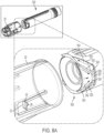
- the container body 210 may be used as a tool to couple the needle assembly to the drug device by pushing the container body 210 straight onto the drug device, as will be discussed further in relation to FIG. 8A .
- the container body 210 is then removed from the needle assembly 100 by pulling the container body 210 straight off of the drug device and the needle assembly.
- no relative twisting between the container body and the needle assembly and/or the drug device is needed for coupling of the needle assembly to the drug device and/or removal of the container body from the needle assembly. In other embodiments, however, a relative twisting motion may be used.
- the needle assembly 100 includes a carrier 20 and a trigger 30 mounted to the end of the carrier 20.
- the needle assembly 100 also includes a needle 10, where at least a portion of the needle is positioned within the carrier 20. At least a portion of the needle may be positioned within a bore 31 of the trigger 30. Initially, the needle is in a retracted position in which a distal end 14 of the needle does not extend beyond a distal end 34 of the trigger 30.
- a force is exerted upon the trigger 30 in a proximal direction, as represented by the arrow shown in FIG. 6E .
- This force may be created, for example, by pressing the trigger 30 flush against the skin of a subject. Pushing on this trigger actuates the needle 10 to move distally to an extended position, shown in FIG. 6F .
- the distal end 14 of the needle 10 has moved out of the bore 31 of the trigger, and instead is positioned distal to the distal end 34 of the trigger 30.
- FIGS. 7A and 7B illustrate removal of the needle assembly from the drug device.
- a user moves the container body 210 toward the needle assembly until the needle assembly is received within the container body 210.
- a user twists the container body 210 in either direction relative to the drug device. Then, to remove the needle assembly from the drug device, the user pulls the container body 210 straight off and away from the drug device.
- FIG. 8A A detailed view of the coupling end of the drug device and the carrier of the needle assembly is shown in FIG. 8A , with the carrier shown in phantom.
- the carrier 20 includes pawls 22 that interact with the coupling end 550 of the drug device.
- the pawl 22 moves into an on-ramp 552 of the coupling end 550 until the pawl 22 snaps over a snap edge 556 and into a recess 557 to lock the carrier 20 onto the drug device.
- the recess is defined in the sidewall of the device and has a distal boundary defined by the snap edge 556, a proximal boundary defined by the device body, and a pair of circumferential boundaries defined by bumps 524.
- the wall thickness of the coupling end varies in a manner such that there may be only clearance for pawls 22 to enter the on-ramps and thus into a coupling arrangement at certain angular orientations.
- FIGS. 9A-9C depict the carrier in the process of being removed from the first portion of the drug device.
- the carrier pawls 22 first climb up removal bumps 524 on the drug device. Sliding of the carrier pawls 22 against the removal bumps provides a detent feel. The pawls 22 then encounter and enter off-ramps 554 of the drug device. Continued relative twisting causes the carrier pawls to slide along the helical sides 525 of the off-ramps ( FIG. 9B ), resulting in separation of the carrier from the drug device ( FIG. 9C ).
- the radial elevation of the off-ramps 554 may be greater than the elevation of the on-ramps
- FIGS. 11A-11F Detailed views of the carrier are provided at FIGS. 11A-11F .
- FIGS. 12A-12E Detailed views of the first portion of the drug device and its coupling end are provided at FIGS. 12A-12E .
- FIG. 10B the carrier 20 has been pushed onto the first portion 502 of the drug device to engage and align the carrier to the first portion 502 of the drug device.
- the needle 10 has not yet entered the septum 520 of the drug device.
- the proximal end 12 of the needle 10 pierces through the septum 520 of the drug device.
- the trigger 30 includes a rib 35 that interacts with legs 41 of the hub 40, as will be discussed below.
- Engagement of the carrier 20 to the drug device also axially compresses a drive spring 560 located on the drug device against the trigger 30, also referred to as loading the spring.
- the spring 560 remains compressed due to engagement of the carrier 20 to the drug device, and due to the needle hub being initially locked to the carrier.
- each of the legs 41 includes a notch region 41a defined by a radial portion 41b extending outward from an axial leg portion 41c.
- a catch surface 41d is therefore formed that engages exterior surface 29a of a ledge 29.
- the exterior surface 29a is sized to fit within the not 41a to facilitate a fixed position prior to deployment. It should be appreciated that in some embodiments, engagement of the carrier 20 to the drug device need not load the drive spring 560.
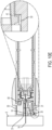
- FIG. 10D shows the trigger 30 of the drug delivery device being pushed against skin 5 of a subject.
- the trigger 30 moves in a proximal direction toward the needle carrier 20.
- movement of the trigger in the proximal direction causes a contact surface 36 of the trigger rib 35 to contact and push against a hub leg 41 of the needle hub 40, thus moving the hub leg 41 radially inward until the hub leg clears the inner surface of the rib 35 and releases from a ledge 29 of the carrier 20, thus freeing the needle hub 40 to be moveable relative to the carrier 20.
- the spring 560 which had been exerting a force against the needle hub, is free to axially expand and release its stored potential energy, pushing the needle hub 40 to move distally relative to the carrier, as shown in FIG. 10E .
- the needle 10 which is attached to the needle hub 40, moves distally together with the needle hub into an extension position in which the distal end 14 of the needle 10 moves through the bore 31 of the trigger 30 and pierces into the subject's skin 5.
- distal movement of the needle hub causes the needle hub legs 41 to move toward and into radial recesses 33 in the interior of trigger 30, locking the hub 40 to the trigger 30.
- the needle hub locked in place the needle cannot be redeployed.
- FIGS. 13A-13E Detailed views of the needle hub are provided at FIGS. 13A-13E .
- Detailed views of the trigger are provided at FIGS.14A-14F .
- FIG. 10F shows the container body 210 being used to remove the needle assembly 100 from the drug device.
- the container body 210 may serve as sharps protection to help prevent the needle from being inadvertently contacted.
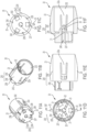
- FIGS. 11A-11F depict various views of the needle carrier 20 according to one illustrative embodiment.
- the fins 23 that are received by the recesses of the container body can be seen in the perspective views of FIGS. 11A and 11B , as well as in the end views of FIGS. 11C and 11D , and the side view of FIG. 11E .
- the guide ribs 21 can be seen in the cross-sectional view of FIG. 11F
- the pawls 22 can be seen in FIGS. 11B, 11D, and 11F .
- the needle carrier 20 includes a generally cup-shaped cylindrical carrier body 230 defining a cavity 232 therein.
- the carrier body 230 includes a head portion 234 with a reduced cross-sectional area relative to the body portion 236.
- the fins 23 are shown extending axially along and radially outward from the body portion 236.
- the pawls 22 are formed at the end of pawl arms 22a along the body portion 236.
- the head portion 234 is configured to receive the trigger 30 (not shown) which is shaped to fit over the head portion 234.
- the head portion 234 includes axial slots to receive guide ribs.
- a first of the axial slots 242 are configured to receive support ribs 244.
- a second of the axial slots 238 are configured to receive the trigger guide ribs 35.
- Head portion defines a longitudinal bore 240 extending therein.
- the guide ribs 21 may be defined as a continuous surface that defines the bore such the proximal end of the guide ribs 21, with the radial tips 25 protruding within cavity 232 of the body portion. Bore 237 is formed in the end wall 239 of the head portion 234.
- FIGS. 13A-13E depict various views of the needle hub 40 according to one illustrative embodiment.
- the needle hub 40 includes a plurality of legs 41 that are able to move in the radially inward and outward direction.
- the hub also includes slots 45 configured to receive the guide ribs 21 from the carrier 20.
- the hub 40 also includes a bore 43 through which a needle is positioned.
- the needle may be fixed to the hub in any suitable manner, for example via an adhesive, insert molding, mechanical interlock, welding, being integrally formed with the needle, UV light activated glue, or any other suitable arrangement.
- Hub 40 may have a generally cup-shaped body 50 having an axial end wall 52 and a cylindrical sidewall 54 extend from the end wall. Legs 41 are formed along the sidewall.
- legs 41 there are three legs circumferentially spaced apart.
- Legs 41 may be integrally formed in to the sidewall 54 and cantilevered attached thereto such that the leg 41 can flex.
- a center axial body 56 is shown extending distally from the end wall 52 and includes the bore 43.
- Slots 45 are shown having a first portion 57 formed in the end wall 52 and extending radially outward from the center body 56 and a second portion 58 extending axially along the sidewall 54.
- FIGS. 14A-14F depict various views of the trigger 30 according to one illustrative embodiment.
- the trigger includes ribs 35 having a contact surface 36 for pushing the needle hub legs radially inward to release the needle hub for needle extension, as described above.
- a recess 33 distal to the ribs receives the needle hub leg after needle extension to lock the needle hub in place to prevent subsequent needle deployments.
- Trigger 30 includes a cup-shaped body 60 with an axial end wall 62 and cylindrical sidewall 64 shaped to define a trigger cavity 66 to receive the head portion 234 of the carrier body 230.
- Ribs 35 are axially disposed along the inner surface of the sidewall and circumferentially spaced apart from one another.
- Support ribs 244 are axially interdisposed between the ribs 35 along the inner surface and circumferentially spaced apart from one another.
- Bore 31 is formed in the end wall 62.
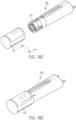
- FIGS. 15A-15F depict various views of the container body 210 according to one illustrative embodiment.
- the container body includes recesses 213 that receive the fins 23 of the needle carrier to couple the container body to the needle assembly.
- the body 210 is generally cup-shaped with an axial end wall 214 and a sidewall 215 extending from the end wall 214 to define a container cavity 216 sized and shaped to receive the carrier 20.
- a radial flange 217 may extend from the proximal end of the sidewall 215 and sized to provide more contact surface for the cover seal.
- Recesses 213 are defined along the inner surface of the sidewall.
- the end wall 214 may be generally hemispherical.
- a drug delivery device may be configured such that the needle of the device remains hidden from a subject throughout all operational steps of the device.
- the needle may remain hidden during attachment of a needle assembly to a drug device and during removal of the needle assembly from the drug device.
- the drug delivery device may include a deployment mechanism that moves the needle from a retracted position to an extended position to pierce a subject and permit delivery of medicament to the subject, and a retraction mechanism that retracts the needle after injection of the medicament.
- the first portion 1502 of the drug device may include a coupling end 1550 for coupling to the needle assembly 1000.
- FIG. 16B illustrates a process of coupling a needle carrier 1120 of the needle assembly 1000 to the drug device.
- a user pushes the carrier onto the drug device, turns the carrier relative to the drug device, and then again pushes the carrier further onto the drug device.
- the drug delivery device is set for injection by pulling back on the actuator 1590.
- actuation mechanisms may be integrated into the drug delivery device, and what is shown in the provided illustrative embodiments are not intended to limit the drug delivery device.
- actuation of the device actuator 1590 may cause multiple actions to occur.
- pressing down on the actuator 1590 may cause a needle 1010 to extend from the needle carrier 1120 and pierce into the skin 5.
- the device may permit medicament to be expelled from the medicament container, out through the needle, and into the subject.
- the device may retract the needle back into the needle carrier 1120.
- the drug delivery device includes a needle assembly, including a needle 1010, a carrier 1120, a needle hub 1040, and a cam 1050.
- the carrier 1120 may initially house the other components of the needle assembly.
- a proximal cover 1220 may be positioned on a proximal end of the carrier 1120, and a distal cover 1221 may be positioned on a distal end of the carrier 1120.
- the proximal cover 1220 is removable from the needle carrier 1120 in order to expose the components within the carrier and to permit coupling of the needle carrier to a drug device.
- the proximal cover is a peelable seal.
- the distal cover 1221 is not configured to be removed, but instead is configured to be pierced through by a needle. In other embodiments, however, the distal cover 1221 is configured to be removed.
- the drug device side may include a first portion 1502 and a second portion 1504.
- the first portion 1502 may house a medicament container.
- the second portion 1504 may include a device actuator, and may include an actuation mechanism that serves to trigger release of medicament from a medicament container.
- the drug device also includes a collar 1570, a drive spring 1560, a retraction trigger 1582, and an extension trigger 1584.
- the drive spring 1560 is a torsion spring.
- FIGS. 18A-18G depict the drug delivery device of FIG. 17 undergoing a sequence of steps including coupling of a needle assembly to a drug device, extension of a needle, and retraction of the needle.
- components of a needle assembly are initially held within the needle carrier 1120, which is sealed via a proximal cover 1220 and a distal cover 1221.
- the proximal cover 1220 is removed from the carrier 1120, exposing the other components of the needle assembly and preparing the carrier 1120 to be coupled to a coupling end 1550 of a first portion 1502 of a drug device.
- the first portion 502 of the drug device includes a collar 1570 at the coupling end 1550 of the drug device.
- the collar 1570 is rotatable between a deactivated orientation in which the needle carrier cannot be coupled to the collar, and an activated orientation in which the needle carrier can be coupled to the collar.
- FIG. 18B shows the collar in the deactivated state. In this state, the needle carrier 1120 is physically blocked from sliding onto the collar.
- FIG. 18C the collar 1570 has been rotated to an activated orientation.
- the needle carrier can now be slid onto the collar 1570.
- a user first pushes the carrier 1120 onto the collar, then rotates the carrier relative to the collar, and finally pushes the carrier further onto the collar, resulting in the needle assembly being coupled to the drug device as shown in FIGS. 18D and 18E .
- the needle carrier may be retained to the drug device via a detent, which will be discussed in further detail below.
- a user actuates the drug device and causes the extension trigger 1584 to activate, which causes needle 1010 to move from a retracted position to an extended position, piercing through distal cover 1221 in the process.
- both the extension and retraction triggers are provided; however the present disclosure is not limited in this regard.
- only the extension trigger is provided.
- only the retraction trigger is provided.
- a retraction trigger 1582 is activated, which causes the needle 1010 to move back to a retracted position within the carrier 1120.
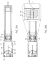
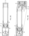
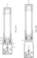
- FIGS. 20A-20F A series of cross-sectional views of the drug delivery device of FIG. 17 as the device undergoes a sequence of operational steps is provided at FIGS. 20A-20F .
- FIG. 20A shows the drug delivery device in a state in which the needle assembly is not yet coupled to the drug device.
- the needle assembly includes a needle carrier 1120, as well as a needle 1010, needle hub 1040 and cam 1050 housed within the needle carrier 1120.
- a distal cover 1221 is also located at a distal end of the needle carrier 1120.
- the drug device On the drug device side, the drug device includes a collar 1570 and a torsion spring 1560.
- the collar 1570 is shown in a deactivated state.
- the collar In the deactivated state, the collar is in a rotational orientation relative to the needle carrier that prevents the needle carrier from sliding onto the collar.
- collar arms 1571 are aligned with tabs 1121 of the needle carrier. The presence of the collar arms 1571 physically interfere with the tabs 1121 of the needle carrier, thus preventing the needle carrier from being moved onto the collar.
- the collar can be rotated to an activated state relative to the needle carrier.
- the activated state slots 1572 on the collar are now rotationally aligned with the carrier tabs 1121, thus giving the carrier clearance to be pushed onto the collar.
- the spring 1560 is initially held in a wound state. In other words, prior to actuation of the drug delivery device, the spring 1560 has stored spring potential energy. With the collar in the position shown in FIG. 20B , the spring 1560 is held in its wound state by the presence of extension trigger 1584. As shown in the enlarged view of FIG. 20B , the extension trigger 1584 physically blocks the collar 1570 from rotating, which in turn prevents the spring 1560 from being able to unwind.
- FIG. 20C shows the needle carrier 1120 pushed onto the collar 1570, with the carrier tabs 1121 received within the slots of the collar. At this initial engagement stage, the needle 1010 has not yet entered the septum 1520 of the medicament container 1530.
- the drug delivery device is held against the skin 5 of the subject, with the distal cover 1221 at the end of the needle carrier being held in contact against the skin.
- the user actuates the drug delivery device to pull back on the extension trigger 1584, moving the trigger in the proximal direction, which frees the collar 1570 to rotate due to unwinding of the torsion spring 1560.
- Rotation of the collar rotates the cam 1050, which, because the radial ends 1052 of the arms 1041 ride on the cam surfaces 1051, causes the needle hub 1040 to extend the needle 1010, moving the needle from a retracted position to an extended position in which the distal end 1014 of the needle 1010 penetrates through the distal cover 1221 and into the subject's skin 5, as shown in FIG. 20E .
- the needle assembly may be removed from the drug device after injection of medicament.
- the needle carrier 1120 is removed from the collar 1570 by pulling the carrier off of the collar in a distal direction.
- the tabs 1121 of the carrier slide out of the slots 1572 of the collar, and the arms 1571 flex radially inwardly to permit removal of the carrier from the collar.
- the carrier is shown fully removed from the drug device in FIG. 21B .
- the needle carrier 1120 is a multi-function component in that the carrier may be used to mount the needle assembly to the device, may remain with the needle assembly for operation of the device, may be used as a tool to remove the needle assembly from the device, and contains the used needle assembly after use.
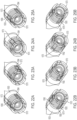
- FIGS. 22A-25B depict the rotational positions of the collar relative to the drug device of the embodiment of FIG. 17 as the drug delivery device undergoes a sequence of operational steps.
- the collar is shown in phantom.
- FIGS. 22A and 22B show two perspective views of the collar prior to use, when the collar is in the deactivated state.
- the collar is rotationally mounted to a housing 1503 of the first portion of the drug device.
- the collar includes first and second collar stops 1573 and 1575 that are initially in contact against the housing 1503.
- the first collar stop 1573 is initially in contact with first housing stop 1509.
- the second collar stop 1575 is initially in contact with second housing stop 1505.
- FIGS. 31A-31E Detailed views of the collar are shown in FIGS. 31A-31E
- detailed views of the housing are shown in FIGS. 32A-32D .
- the collar is permitted to rotate due to unwinding of the spring 1560 until the second collar stop 1575 contacts the retraction trigger 1582, as shown in FIG. 24B .
- the first collar stop 1573 is in the air, as shown in FIG. 24A .
- FIGS. 26A-26C depict the arrangements of the cam and needle hub of the needle assembly as the drug delivery device undergoes a sequence of needle extension steps.
- the carrier is shown in phantom.
- FIG. 26A shows the cam 1050 in the initial angular position prior to use of the drug delivery device.
- the cam may include tabs 1055 that are initially aligned with the carrier tabs 1121 to permit coupling of the carrier 1120 with the collar of the drug device.
- the cam may include detents 1056 that are received by an inner wall surface 1129 of the carrier 1120 to help maintain the position of the cam within the carrier prior to use.
- the cam may include teeth 1054 that abut against arms 1041 of the needle hub 1040 to retain the hub in place during piercing of the septum with the proximal end of the needle.
- the cam may include extension cam surfaces 1051 (also referred to as extension helices 1051) on which rides the radial ends 1052 of the arms 1041.
- the cam may also include retraction cam surfaces (also referred to as retraction helices 1053) defined by radially inwardly extending lips 1053a that also interacts with a radial end 1052 of an arm 1041 during rotation of the cam. Specifically, a first surface 1057 (see FIG.
- FIGS. 30A-30D Detailed views of the hub are shown in FIGS. 30A-30D and detailed views of the cam are shown in FIGS. 29A-29F .
- FIG. 26B shows the state of the cam an intermediate angular position when the extension trigger has been released and the collar rotates, causing the cam to rotate (shown in the counter clockwise direction) as well.
- Rotation of the cam causes the extension helices 1051 of the cam to push against the arms 1041 of the hub, driving the hub 1040 in the distal direction to move the needle 1010 into an extended position, shown in FIG. 26C , where the cam is at the final angular position for needle extension.
- the hub 1040 is held between the cam's extension helices 1051 and retraction helices 1053.
- FIGS. 27A and 27B depict the arrangements of the needle carrier as the drug delivery device undergoes a sequence of needle retraction steps.
- FIG. 27A shows the state of the cam when the retraction trigger has been released and the collar rotates, causing the cam to rotate as well (still in the counter clockwise direction). Rotation of the cam causes the retraction helices 1053 to pull against the arms 1041 of the hub 1040 in the proximal direction, thus moving the needle 1010 into a retracted position, shown in FIG. 27B .
- the internal radial lip 1053a is formed along the retraction helices 1053 that catches the end of the arms of the needle hub during retraction.
- FIGS. 28A-28F depict various views of the needle carrier 1120 according to one illustrative embodiment.
- the needle carrier 1120 includes a cylindrical body 1123.
- the tabs 1121 are formed on the inner wall of the body adjacent to an end and extend along a portion of the axial length of the body 1123 and extend radially inwardly.
- a central bore region 1124 extends along the central axis and acts to guide the hub, specifically the central axle 1058 of the hub 1040 (see FIG. 30A ).
- Radially inwardly extending struts 1125 attach the hub guide to the inner wall of the body.
- a bearing surface 1126 on each strut supports the central bore 1062 of the cam 1050. Retention snaps hold the cam to the carrier 1120.
- Cam rotation detents 1128 (start of cam rotation) and cam rotation snaps 1129 (end of cam rotation) limit the extent of rotational displacement of the cam..
- FIGS. 29A-29F depict various views of the cam 1050 according to one illustrative embodiment.
- the cam 1050 includes a generally cylindrical body 1060 on which the extension cam surfaces 1051 and retraction cam surfaces 1053 are formed. Also formed on the body is are the tabs 1055.
- the body further includes a bearing wall 1061 through which extends the central bore 1062.
- the cam may include teeth 1054 (which in this embodiment extends axially on the cylindrical body in the same direction as the cam surfaces), detents 1056 (which are provided on the outer cylindrical body at an apex of the retraction cam surface), extension helices 1051 and retraction helices 1053.
- FIGS. 30A-30D depict various views of the needle hub 1040 according to one illustrative embodiment.
- the hub may include arms 1041 that interact with the cam of the needle assembly during extension and retraction of a needle.
- the hub includes a central axle 1058.
- the axle1058 may also include a bore 1043 through which the needle extends.
- the radially extending arms 1041 is sized to fit within the space 1127 formed in the central bore region 1124 of the needle carrier 1120.
- Each arm 1041 includes a radial end 1052 having first surface 1057 and second surface 1059.
- FIGS. 31A-31E depict various views of the collar 1570 according to one illustrative embodiment.
- the collar has a generally cylindrical body 1580 formed with arms 1571 and slots 1572.
- the arms include an abutment surface 1581 that precludes the insertion of the needle carrier 1120 along the slot 1582 defined by the arm 1571.
- the arms also include a ramp 1584 that causes the arm to flex radially inward (due to the gap 1583 between the arms and the body) to permit removal of the needle carrier.
- the slots 1572 may be configured to receive tabs of the needle carrier upon insertion, as discussed above.
- FIGS. 32A-32D depict various views of the housing 1503 of the first portion 1502 of the drug device according to one illustrative embodiment.
- the housing 1503 may include a first housing stop 1509 and a second housing stop 1505 that interact with the collar during operation of the device.
- the housing may include a retraction trigger slot 1512 through which a retraction trigger can move, as well as an extension trigger slot 1514 through which an extension trigger can move.
- the housing may also include alignment slots 1506 configured to receive tabs of the needle carrier during coupling of the needle carrier to the housing.
- a trigger slot 1590 may be formed on an inner wall of the housing.
- the distal end of the housing includes the collar retention groove 1587.
- the drug devices shown are illustrative, as the needle assemblies described herein can be adapted for use with variously configured drug devices, including differently constructed pen-shaped medication injection devices, differently shaped injection devices, and infusion pump devices.
- the medication may be any of a type that may be delivered by such a drug device.
- the devices shown are intended to be illustrative and not limiting as the needle assemblies described may be used in other differently configured devices.
- the phrases "at least one of ⁇ A>, ⁇ B>, . . . and ⁇ N>” or "at least one of ⁇ A>, ⁇ B>, ... ⁇ N>, or combinations thereof" or " ⁇ A>, ⁇ B>, . . . and/or ⁇ N>” are defined by the Applicant in the broadest sense, superseding any other implied definitions hereinbefore or hereinafter unless expressly asserted by the Applicant to the contrary, to mean one or more elements selected from the group comprising A, B, . . . and N.
- the phrases mean any combination of one or more of the elements A, B, . . . or N including any one element alone or the one element in combination with one or more of the other elements which may also include, in combination, additional elements not listed.
Landscapes
- Health & Medical Sciences (AREA)
- Vascular Medicine (AREA)
- Engineering & Computer Science (AREA)
- Anesthesiology (AREA)
- Biomedical Technology (AREA)
- Heart & Thoracic Surgery (AREA)
- Hematology (AREA)
- Life Sciences & Earth Sciences (AREA)
- Animal Behavior & Ethology (AREA)
- General Health & Medical Sciences (AREA)
- Public Health (AREA)
- Veterinary Medicine (AREA)
- Infusion, Injection, And Reservoir Apparatuses (AREA)
Applications Claiming Priority (3)
| Application Number | Priority Date | Filing Date | Title |
|---|---|---|---|
| US201962898744P | 2019-09-11 | 2019-09-11 | |
| EP20775510.9A EP4028083B1 (de) | 2019-09-11 | 2020-09-04 | Medikamentenabgabevorrichtung mit nadelträger |
| PCT/US2020/049434 WO2021050384A1 (en) | 2019-09-11 | 2020-09-04 | Medication delivery device with needle carrier |
Related Parent Applications (2)
| Application Number | Title | Priority Date | Filing Date |
|---|---|---|---|
| EP20775510.9A Division EP4028083B1 (de) | 2019-09-11 | 2020-09-04 | Medikamentenabgabevorrichtung mit nadelträger |
| EP20775510.9A Division-Into EP4028083B1 (de) | 2019-09-11 | 2020-09-04 | Medikamentenabgabevorrichtung mit nadelträger |
Publications (2)
| Publication Number | Publication Date |
|---|---|
| EP4537875A2 true EP4537875A2 (de) | 2025-04-16 |
| EP4537875A3 EP4537875A3 (de) | 2025-06-11 |
Family
ID=72561989
Family Applications (2)
| Application Number | Title | Priority Date | Filing Date |
|---|---|---|---|
| EP25160216.5A Pending EP4537875A3 (de) | 2019-09-11 | 2020-09-04 | Medikamentenabgabevorrichtung mit nadelträger |
| EP20775510.9A Active EP4028083B1 (de) | 2019-09-11 | 2020-09-04 | Medikamentenabgabevorrichtung mit nadelträger |
Family Applications After (1)
| Application Number | Title | Priority Date | Filing Date |
|---|---|---|---|
| EP20775510.9A Active EP4028083B1 (de) | 2019-09-11 | 2020-09-04 | Medikamentenabgabevorrichtung mit nadelträger |
Country Status (6)
| Country | Link |
|---|---|
| US (1) | US20220355035A1 (de) |
| EP (2) | EP4537875A3 (de) |
| JP (1) | JP7686628B2 (de) |
| CN (1) | CN114340702B (de) |
| ES (1) | ES3025084T3 (de) |
| WO (1) | WO2021050384A1 (de) |
Families Citing this family (5)
| Publication number | Priority date | Publication date | Assignee | Title |
|---|---|---|---|---|
| EP4716568A1 (de) * | 2023-05-23 | 2026-04-01 | Novo Nordisk A/S | Nadelschutzeinheit mit betätigbarer behälterkupplung |
| CN121194810A (zh) * | 2023-05-23 | 2025-12-23 | 诺和诺德股份有限公司 | 具有可致动释放特征的受防护的针单元 |
| EP4716565A1 (de) * | 2023-05-23 | 2026-04-01 | Novo Nordisk A/S | Nadelschutzeinheit mit betätigbarem montagemerkmal |
| WO2025114263A1 (en) * | 2023-11-28 | 2025-06-05 | Novo Nordisk A/S | Drug delivery device with safety release member |
| EP4563170A1 (de) * | 2023-11-29 | 2025-06-04 | Sensile Medical AG | Nadelvorrichtung, medizinische vorrichtung und medizinisches vorrichtungssystem |
Family Cites Families (8)
| Publication number | Priority date | Publication date | Assignee | Title |
|---|---|---|---|---|
| KR100763050B1 (ko) * | 2004-03-31 | 2007-10-04 | 일라이 릴리 앤드 캄파니 | 액체 약품을 전달하기 위한 니들 카세트를 갖는 주입 장치 |
| CN101945680B (zh) * | 2008-01-15 | 2013-08-21 | 贝克顿·迪金森公司 | 具有针插入机构的笔针组件 |
| GB2467904B (en) * | 2009-02-17 | 2013-06-12 | Oval Medical Technologies Ltd | Drug container and delivery mechanism |
| CA2753812C (en) * | 2009-03-13 | 2015-07-21 | Eli Lilly And Company | Apparatus for injecting a pharmaceutical with automatic syringe retraction following injection |
| WO2014060563A2 (en) * | 2012-10-17 | 2014-04-24 | Oval Medical Technologies Limited | Automatic drug delivery devices |
| WO2014195183A1 (en) | 2013-06-03 | 2014-12-11 | Novo Nordisk A/S | Medical injection device |
| EP3848072A1 (de) | 2014-12-19 | 2021-07-14 | Amgen Inc. | Medikamentenabgabevorrichtung mit näherungssensor |
| WO2016173895A1 (en) * | 2015-04-28 | 2016-11-03 | Novo Nordisk A/S | A medical injection device with telescopically movable needle shield having a cleaning chamber for the needle |
-
2020
- 2020-09-04 CN CN202080064002.0A patent/CN114340702B/zh active Active
- 2020-09-04 WO PCT/US2020/049434 patent/WO2021050384A1/en not_active Ceased
- 2020-09-04 ES ES20775510T patent/ES3025084T3/es active Active
- 2020-09-04 US US17/641,857 patent/US20220355035A1/en active Pending
- 2020-09-04 EP EP25160216.5A patent/EP4537875A3/de active Pending
- 2020-09-04 EP EP20775510.9A patent/EP4028083B1/de active Active
- 2020-09-04 JP JP2022515812A patent/JP7686628B2/ja active Active
Also Published As
| Publication number | Publication date |
|---|---|
| EP4028083A1 (de) | 2022-07-20 |
| EP4537875A3 (de) | 2025-06-11 |
| CN114340702B (zh) | 2025-08-15 |
| US20220355035A1 (en) | 2022-11-10 |
| WO2021050384A1 (en) | 2021-03-18 |
| JP7686628B2 (ja) | 2025-06-02 |
| JP2022547968A (ja) | 2022-11-16 |
| ES3025084T3 (en) | 2025-06-06 |
| CN114340702A (zh) | 2022-04-12 |
| EP4028083B1 (de) | 2025-04-09 |
Similar Documents
| Publication | Publication Date | Title |
|---|---|---|
| EP4028083B1 (de) | Medikamentenabgabevorrichtung mit nadelträger | |
| AU2019213383B2 (en) | An auto-injector for epinephrine injection | |
| CN103957963B (zh) | 用于两种剂量的药物的自动注射的设备 | |
| KR101965559B1 (ko) | 약물 투여량의 자동 주입을 위한 장치 | |
| CN101903057B (zh) | 具有针头插入部的自动注射装置 | |
| JP5373916B2 (ja) | 連結された本体部分を備える医療用インジェクター | |
| JP6139697B2 (ja) | 薬剤送達装置 | |
| CN108367118A (zh) | 注射装置 | |
| US20200108211A1 (en) | Auto injector with recap prevention | |
| JP5721850B2 (ja) | 薬剤送達装置 | |
| EP3405234B1 (de) | Autoinjector apparat | |
| US12611508B2 (en) | Medication delivery device with needle carrier | |
| JP6824262B2 (ja) | 充填済み薬剤送達装置の製造方法 | |
| US11395884B2 (en) | Mechanism for reducing risk of drug contamination | |
| US20260077132A1 (en) | Power assist for a manual and autoinjector injection device | |
| WO2024223331A1 (en) | Reusable automatic medicament delivery device | |
| WO2025253369A1 (en) | Automatic cannula inserter with reusable and disposable parts |
Legal Events
| Date | Code | Title | Description |
|---|---|---|---|
| PUAI | Public reference made under article 153(3) epc to a published international application that has entered the european phase |
Free format text: ORIGINAL CODE: 0009012 |
|
| STAA | Information on the status of an ep patent application or granted ep patent |
Free format text: STATUS: THE APPLICATION HAS BEEN PUBLISHED |
|
| AC | Divisional application: reference to earlier application |
Ref document number: 4028083 Country of ref document: EP Kind code of ref document: P |
|
| AK | Designated contracting states |
Kind code of ref document: A2 Designated state(s): AL AT BE BG CH CY CZ DE DK EE ES FI FR GB GR HR HU IE IS IT LI LT LU LV MC MK MT NL NO PL PT RO RS SE SI SK SM TR |
|
| REG | Reference to a national code |
Ref country code: DE Ref legal event code: R079 Free format text: PREVIOUS MAIN CLASS: A61M0005200000 Ipc: A61M0005320000 |
|
| PUAL | Search report despatched |
Free format text: ORIGINAL CODE: 0009013 |
|
| P01 | Opt-out of the competence of the unified patent court (upc) registered |
Free format text: CASE NUMBER: APP_20632/2025 Effective date: 20250430 |
|
| AK | Designated contracting states |
Kind code of ref document: A3 Designated state(s): AL AT BE BG CH CY CZ DE DK EE ES FI FR GB GR HR HU IE IS IT LI LT LU LV MC MK MT NL NO PL PT RO RS SE SI SK SM TR |
|
| RIC1 | Information provided on ipc code assigned before grant |
Ipc: A61M 5/24 20060101ALN20250506BHEP Ipc: A61M 5/20 20060101ALI20250506BHEP Ipc: A61M 5/34 20060101ALI20250506BHEP Ipc: A61M 5/32 20060101AFI20250506BHEP |
|
| STAA | Information on the status of an ep patent application or granted ep patent |
Free format text: STATUS: REQUEST FOR EXAMINATION WAS MADE |
|
| 17P | Request for examination filed |
Effective date: 20251127 |
|
| GRAP | Despatch of communication of intention to grant a patent |
Free format text: ORIGINAL CODE: EPIDOSNIGR1 |
|
| STAA | Information on the status of an ep patent application or granted ep patent |
Free format text: STATUS: GRANT OF PATENT IS INTENDED |
|
| RIC1 | Information provided on ipc code assigned before grant |
Ipc: A61M 5/32 20060101AFI20260303BHEP Ipc: A61M 5/34 20060101ALI20260303BHEP Ipc: A61M 5/20 20060101ALI20260303BHEP Ipc: A61M 5/24 20060101ALN20260303BHEP |
|
| INTG | Intention to grant announced |
Effective date: 20260316 |