EP4537705A1 - Slide rail assembly - Google Patents
Slide rail assembly Download PDFInfo
- Publication number
- EP4537705A1 EP4537705A1 EP24170777.7A EP24170777A EP4537705A1 EP 4537705 A1 EP4537705 A1 EP 4537705A1 EP 24170777 A EP24170777 A EP 24170777A EP 4537705 A1 EP4537705 A1 EP 4537705A1
- Authority
- EP
- European Patent Office
- Prior art keywords
- rail
- slide rail
- operating member
- locking member
- operating
- Prior art date
- Legal status (The legal status is an assumption and is not a legal conclusion. Google has not performed a legal analysis and makes no representation as to the accuracy of the status listed.)
- Granted
Links
Images






Classifications
-
- A—HUMAN NECESSITIES
- A47—FURNITURE; DOMESTIC ARTICLES OR APPLIANCES; COFFEE MILLS; SPICE MILLS; SUCTION CLEANERS IN GENERAL
- A47B—TABLES; DESKS; OFFICE FURNITURE; CABINETS; DRAWERS; GENERAL DETAILS OF FURNITURE
- A47B88/00—Drawers for tables, cabinets or like furniture; Guides for drawers
- A47B88/50—Safety devices or the like for drawers
-
- A—HUMAN NECESSITIES
- A47—FURNITURE; DOMESTIC ARTICLES OR APPLIANCES; COFFEE MILLS; SPICE MILLS; SUCTION CLEANERS IN GENERAL
- A47B—TABLES; DESKS; OFFICE FURNITURE; CABINETS; DRAWERS; GENERAL DETAILS OF FURNITURE
- A47B88/00—Drawers for tables, cabinets or like furniture; Guides for drawers
- A47B88/40—Sliding drawers; Slides or guides therefor
- A47B88/473—Braking devices, e.g. linear or rotational dampers or friction brakes; Buffers; End stops
- A47B88/477—Buffers; End stops
-
- E—FIXED CONSTRUCTIONS
- E05—LOCKS; KEYS; WINDOW OR DOOR FITTINGS; SAFES
- E05B—LOCKS; ACCESSORIES THEREFOR; HANDCUFFS
- E05B65/00—Locks or fastenings for special use
- E05B65/46—Locks or fastenings for special use for drawers
-
- H—ELECTRICITY
- H05—ELECTRIC TECHNIQUES NOT OTHERWISE PROVIDED FOR
- H05K—PRINTED CIRCUITS; CASINGS OR CONSTRUCTIONAL DETAILS OF ELECTRIC APPARATUS; MANUFACTURE OF ASSEMBLAGES OF ELECTRICAL COMPONENTS
- H05K7/00—Constructional details common to different types of electric apparatus
- H05K7/14—Mounting supporting structure in casing or on frame or rack
- H05K7/1485—Servers; Data center rooms, e.g. 19-inch computer racks
- H05K7/1488—Cabinets therefor, e.g. chassis or racks or mechanical interfaces between blades and support structures
- H05K7/1489—Cabinets therefor, e.g. chassis or racks or mechanical interfaces between blades and support structures characterized by the mounting of blades therein, e.g. brackets, rails, trays
-
- A—HUMAN NECESSITIES
- A47—FURNITURE; DOMESTIC ARTICLES OR APPLIANCES; COFFEE MILLS; SPICE MILLS; SUCTION CLEANERS IN GENERAL
- A47B—TABLES; DESKS; OFFICE FURNITURE; CABINETS; DRAWERS; GENERAL DETAILS OF FURNITURE
- A47B88/00—Drawers for tables, cabinets or like furniture; Guides for drawers
- A47B88/40—Sliding drawers; Slides or guides therefor
- A47B88/423—Fastening devices for slides or guides
- A47B2088/4235—Fastening devices for slides or guides having a latch mechanism coupling or disconnecting a drawer with drawer side slide from the rest of the slide members
Definitions
- the present invention is related to a slide rail assembly.
- US patent number US 6,883,884 B2 discloses a latch assembly for a slide rail device.
- the slide rail device comprises a first rail and a second rail movable relative to each other.
- the first rail is arranged with a latch assembly
- the second rail is arranged with a latch base.
- the present invention aims at providing a slide rail assembly.
- the claimed slide rail assembly comprises a first rail, a second rail, two operating members and a locking member.
- the second rail is movable relative to the first rail.
- the blocking feature is arranged on the first rail.
- the two operating members are movably mounted on the second rail.
- the locking member is movably mounted on the second rail.
- a slide rail assembly 20 comprises a first rail 22 and a second rail 24 longitudinally movable relative to each other according to an embodiment of the present invention.
- the slide rail assembly 20 further comprises a third rail 26 movably arranged between the first rail 22 and the second rail 24.
- the third rail 26 is formed with a passage 27 configured to movably mount the second rail 24.
- the X-axis is a longitudinal direction (or a length direction of the slide rail)
- the Y-axis is a transverse direction (or a lateral direction of the slide rail)
- the Z-axis is a vertical direction (or a height direction of the slide rail).
- the slide rail assembly 20 further comprises a blocking feature 28, a locking member 30 and two operating members (such as a first operating member 31 and a second operating member 32) .
- the locking member 30 is configured to work with the blocking feature 28.
- the blocking feature 28 is arranged on one of the first rail 22 and the second rail 24. In the present embodiment, the blocking feature 28 is arranged on the first rail 22, but the present invention is not limited thereto.
- the blocking feature 28 can be directly or indirectly arranged on the first rail 22.
- the blocking feature 28 is a protrusion; or in an alternative embodiment, the blocking feature 28 is a wall around a hole or a groove, but the present invention is not limited thereto.
- the first rail 22 has a first end part 22a and a second end part 22b opposite to each other, such as a front end part and a rear end part.
- the blocking feature 28 is arranged on the first rail 22 and adjacent to the first end part 22a of the first rail 22.
- the locking member 30, the first operating member 31 and the second operating member 32 are movably mounted on the other one of the first rail 22 and the second rail 24.
- the locking member 30, the first operating member 31 and the second operating member 32 are movably mounted on the second rail 24.
- the second rail 24 has a first end part 24a and a second end part 24b opposite to each other, such as a front end part and a rear end part.
- the locking member 30, the first operating member 31 and the second operating member 32 are movably mounted on the second rail 24 and adjacent to the first end part 24a of the second rail 24.
- the second rail 24 is arranged with a housing 34 (as shown in FIG. 1 ) .
- the housing 34 is connected (such as fixed) to the second rail 24 and adjacent to the first end part 24a of the second rail 24, such that the housing 34 can be seen as a part of the second rail 24.
- the housing 34 comprises a first housing part 34a and a second housing part 34b that can be connected to each other (as shown in FIG. 2 ).
- the first housing part 34a and the second housing part 34b are detachably mounted to each other, and an accommodating space is defined between the first housing part 34a and the second housing part 34b.
- the locking member 30, the first operating member 31 and the second operating member 32 are movably arranged on the first housing part 34a on the first end part 24a of the second rail 24. Furthermore, the first housing part 34a and the second housing part 34b are configured to accommodate and/or cover most of the locking member 30, the first operating member 31 and the second operating member 32 for protection. Or, in other alternative embodiments, the locking member 30, the first operating member 31 and the second operating member 32 can be directly arranged on the second rail 24 and adjacent to the first end part 24a of the second rail 24 without being arranged on the housing 34.
- the first operating member 31 and the second operating member 32 are pivotally connected to the first housing part 34a on the second rail 24 through a first shaft 36 and a second shaft 38 respectively.
- At least one of the first shaft 36 and the second shaft 38 is arranged in a direction substantially identical to the transverse direction of the second rail 24.
- both the first shaft 36 and the second shaft 38 are arranged in a direction substantially identical to the transverse direction of the second rail 24 (or the lateral direction of the second rail 24, or the Y-axis direction).
- the first operating member 31 and the second operating member 32 respectively have a first gear structure 40 and a second gear structure 42 configured to mesh with each other.
- the first gear structure 40 and the second gear structure 42 have a plurality of teeth that mesh with each other.
- one of the first operating member 31 and the second operating member 32 comprises a driving part 44.
- the first operating member 31 comprises the driving part 44
- the driving part 44 is configured to drive the locking member 30 to move.
- the slide rail assembly 20 further comprises a return elastic member 46 configured to provide a return elastic force to at least one of the first operating member 31 and the second operating member 32.
- the return elastic member 46 comprises a first elastic section 48a and a second elastic section 48b configured to provide the return elastic force to the first operating member 31 and the second operating member 32 respectively.
- the first operating member 31 and the second operating member 32 are configured to be held in a first state S1 in response to the return elastic force of the return elastic member 46.
- the first operating member 31 and the second operating member 32 respectively comprise a first operating part 50 and a second operating part 52 configured to be operated by a user in a pressing manner.
- the first operating part 50 and the second operating part 52 are located at corresponding positions. Specifically, the first operating part 50 is located at a first height position (such as a lower position) on the second rail 24, and the second operating part 52 is located at a second height position (such as an upper position) on the second rail 24.
- the locking member 30 is pivotally connected to the first housing part 34a on the second rail 24 through a pivot member 53.
- the pivot member 53 is pivotally connected to at least one lug 51 of the first housing part 34a.
- the pivot member 53 is arranged in a direction substantially identical to the height direction of the second rail 24 (such as the Z-axis direction).
- the slide rail assembly 20 further comprises an auxiliary elastic member 54.
- the auxiliary elastic member 54 can be an elastic piece or a component with elasticity configured to provide an auxiliary elastic force, but the present invention is not limited thereto.
- the locking member 30 is configured to be held in a locking state K1 in response to the auxiliary elastic force of the auxiliary elastic member 54.
- the first shaft 36 is located between the first operating part 50 and the driving part 44.
- the first operating member 31 further comprises a first working part 56 located adjacent to the first shaft 36, and the first working part 56 is arranged with the first gear structure 40.
- the second operating member 32 further comprises a second working part 58 located adjacent to the second shaft 38, and the second working part 58 is arranged with the second gear structure 42 configured to mesh with the first gear structure 40.
- a locking part 60 of the locking member 30 and the blocking feature 28 are configured to block each other in order to prevent the second rail 24 from being moved away from the predetermined position P along a predetermined direction D1 (such as an opening direction). More particularly, when the locking member 30 is in the locking state K1, the blocking feature 28 is located on a moving path of the locking part 60 along the longitudinal direction, such that the locking part 60 and the blocking feature 28 are configured to block each other.
- one of the locking member 30 and the first operating member 31 is arranged with a guiding feature 62, such as an inclined surface or an arc surface, but the present invention is not limited thereto.
- the locking member 30 is arranged with at least one guiding feature 62, and the guiding feature 62 is configured to work with the driving part 44 of the first operating member 31.
- the locking member 30 when one of the first operating member 31 and the second operating member 32 is operated (for example, the first operating member 31 is operated), the locking member 30 is configured to be driven to switch from the locking state K1 (as shown in FIG. 5 ) to an unlocking state K2 (as shown in FIG. 7 and FIG. 8 ) in order to allow the second rail 24 to be moved away from the predetermined position P.
- the second rail 24 is able to be moved away from the predetermined position P along the predetermined direction D1.
- the user can apply a first force F1 to one of the first operating member 31 (the first operating part 50 of the first operating member 31) and the second operating member 32 (the second operating part 52 of the second operating member 32) .
- the user applies the first force F1 to the first operating member 31 (the first operating part 50 of the first operating member 31) to drive the first operating member 31 to switch from the first state S1 to a second state S2.
- the driving part 44 of the first operating member 31 is configured to contact the guiding feature 62 of the locking member 30 to easily drive the locking member 30 to switch from the locking state K1 (as shown in FIG. 5 ) to the unlocking state K2 (as shown in FIG. 7 and FIG.
- the blocking feature 28 is no longer located on the moving path of the locking part 60 along the longitudinal direction (for example, the locking part 60 and the blocking feature 28 are not aligned with each other along the longitudinal direction), such that the locking part 60 and the blocking feature 28 no longer block each other (as shown in FIG. 8 ), in order to allow the second rail 24 to be moved from the predetermined position P along the predetermined direction D1.
- the first operating member 31 and the second operating member 32 are configured to interact with each other through the first gear structure 40 and the second gear structure 42 meshing with each other, such that the second operating member 32 is configured to be moved to switch from the first state S1 (as shown in FIG. 5 ) to the second state S2 (as shown in FIG. 7 ) in response to the movement of the first operating member 31.
- the first operating member 31 is moved along a first rotating direction r1 to switch from the first state S1 (as shown in FIG.
- the auxiliary elastic member 54 is in a state of accumulating the auxiliary elastic force.
- the return elastic member 46 is in a state of accumulating the return elastic force.
- the second rail 24 is able to be moved from the predetermined position P along the predetermined direction D1 to another predetermined position (such as an open position) .
- the first operating member 31 and the second operating member 32 is configured to return to the first state S1 (as shown in FIG. 5 ) from the second state S2 (as shown in FIG. 7 ) in response to the return elastic force released by the return elastic member 46, and the locking member 30 is configured to return to the locking state K1 (as shown in FIG. 5 and 6 ) from the unlocking state K2 (as shown in FIG. 7 and 8 ) in response to the auxiliary elastic force released by the auxiliary elastic member 54.
- the locking member 30 when the second operating member 32 is operated, the locking member 30 is also configured to be moved to switch from the locking state K1 (as shown in FIG. 9 ) to the unlocking state K2 (as shown in FIG. 7 and FIG. 8 ) in order to allow the second rail 24 to be moved away from the predetermined position P.
- the second rail 24 is able to be moved from the predetermined position P along the predetermined direction D1.
- the user can apply a second force F2 opposite to the first force F1 to the second operating member 32 (the second operating part 52 of the second operating member 32) as shown in FIG. 9 , in order to press the second operating member 32 to switch from the first state S1 (as shown in FIG. 9 ) to the second state S2 (as shown in FIG. 7 ).
- the first operating member 31 and the second operating member 32 are configured to interact with each other through the first gear structure 40 and the second gear structure 42 meshing with each other, such that the first operating member 31 is configured to be moved to switch from the first state S1 (as shown in FIG. 9 ) to the second state S2 (as shown in FIG. 7 ) in response to the movement of the second operating member 32.
- the driving part 44 of the first operating member 31 is configured to contact the guiding feature 62 of the locking member 30 to easily drive the locking member 30 to switch from the locking state K1 (as shown in FIG. 9 ) to the unlocking state K2 (as shown in FIG. 7 and FIG. 8 ), in order to allow the second rail 24 to be moved from the predetermined position P along the predetermined direction D1.
- the blocking feature 28 is no longer located on the moving path of the locking part 60 along the longitudinal direction (for example, the locking part 60 and the blocking feature 28 are not aligned with each other along the longitudinal direction), such that the locking part 60 and the blocking feature 28 no longer block each other (as shown in FIG. 8 ), in order to allow the second rail 24 to be moved from the predetermined position P along the predetermined direction D1.
- the user can operate the first operating member 31 or the second operating member 32 to unlock the second rail 24 relative to the first rail 22 at the predetermined position P, in order to allow the second rail 24 to be moved away from the predetermined position P.
- a plurality of slide rail assemblies 20 are mounted on a rack 64 (or a cabinet) along the height direction (such as the Z-axis direction), and the slide rail assemblies 20 have substantially the same structural configuration. Furthermore, when the user is going to operate the slide rail assembly 20 mounted at the highest position of the rack 64 with the second rail 24 being locked at the predetermined position P relative to the first rail 22, it is difficult for the user's hand H to reach and operate the second operating member 32 (the second operating part 52 of the second operating member 32) of the slide rail assembly 20 at the highest position. Therefore, the user can operate the first operating member 31 (the first operating part 50 of the first operating member 31) to drive the locking member 30 to switch from the locking state K1 (please also refer to FIG.
- the slide rail assembly 20 according to the embodiments of the present invention has the following technical features:
Landscapes
- Engineering & Computer Science (AREA)
- Computer Hardware Design (AREA)
- General Engineering & Computer Science (AREA)
- Microelectronics & Electronic Packaging (AREA)
- Drawers Of Furniture (AREA)
- Seats For Vehicles (AREA)
Abstract
Description
- The present invention is related to a slide rail assembly.
- US patent number
US 6,883,884 B2 discloses a latch assembly for a slide rail device. The slide rail device comprises a first rail and a second rail movable relative to each other. The first rail is arranged with a latch assembly, and the second rail is arranged with a latch base. When the first rail is located at a retracted position relative to the second rail, the latch assembly is engaged with the latch base, such that the first rail is held at the retracted position. When a user is going to unlock the latch assembly, the user must simultaneously press two actuating members of the latch assembly, such that hooks of two corresponding unlocking members are no longer engaged with the latch base in order to allow the first rail to be moved away from the retracted position relative to the second rail. - However, for different market requirements, it is important to develop a slide rail product capable of unlocking two slide rails relative to each other without requiring simultaneous operation of two actuating members (or operating members).
- This in mind, the present invention aims at providing a slide rail assembly.
- This is achieved by a slide rail assembly according to
claim 1. The dependent claims pertain to corresponding further developments and improvements. - As will be seen more clearly from the detailed description following below, the claimed slide rail assembly comprises a first rail, a second rail, two operating members and a locking member. The second rail is movable relative to the first rail. The blocking feature is arranged on the first rail. The two operating members are movably mounted on the second rail. The locking member is movably mounted on the second rail. When the second rail is located at a predetermined position relative to the first rail and when the locking member is in a locking state, the locking member and the blocking feature are configured to block each other in order to prevent the second rail from being moved away from the predetermined position. When one of the two operating members is operated, the locking member is configured to be driven to switch from the locking state to an unlocking state, such that the locking member and the blocking feature no longer block each other, in order to allow the second rail to be moved away from the predetermined position.
- In the following, the invention is further illustrated by way of example, taking reference to the accompanying drawings thereof:
-
FIG. 1 is a diagram showing a slide rail assembly at least comprising a first rail and a second rail according to an embodiment of the present invention; -
FIG. 2 is an exploded view of the first rail, the second rail and a housing of the slide rail assembly according to the embodiment of the present invention; -
FIG. 3 is an enlarged view of an area A ofFIG. 2 ; -
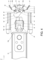
FIG. 4 is a diagram showing a portion of the second rail according to the embodiment of the present invention; -
FIG. 5 is a diagram showing the second rail being locked at a predetermined position relative to the first rail from a viewing angle according to the embodiment of the present invention; -
FIG. 6 is a diagram showing the second rail being locked at the predetermined position relative to the first rail from another viewing angle according to the embodiment of the present invention; -
FIG. 7 is a diagram showing a user operating one of a first operating member and a second operating member to unlock the second rail relative to the first rail from a viewing angle according to the embodiment of the present invention; -
FIG. 8 is a diagram showing the user operating one of the first operating member and the second operating member to unlock the second rail relative to the first rail from another viewing angle according to the embodiment of the present invention; -
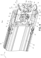
FIG. 9 is a diagram showing the second rail being locked at the predetermined position relative to the fist rail, and the user operating the other one of the first operating member and the second operating member according to the embodiment of the present invention; -
FIG. 10 is a diagram showing a plurality of slide rail assemblies being mounted to a rack, and the user operating the first operating member to unlock the second rail relative to the first rail of the slide rail assembly at the highest position according to the embodiment of the present invention; and -
FIG. 11 is a diagram showing a plurality of slide rail assemblies being mounted to a rack, and the user operating the second operating member to unlock the second rail from the first rail of the slide rail assembly at the lowest position according to the embodiment of the present invention. - As shown in
FIG. 1 andFIG. 2 , aslide rail assembly 20 comprises afirst rail 22 and asecond rail 24 longitudinally movable relative to each other according to an embodiment of the present invention. Preferably, theslide rail assembly 20 further comprises athird rail 26 movably arranged between thefirst rail 22 and thesecond rail 24. Thethird rail 26 is formed with apassage 27 configured to movably mount thesecond rail 24. In addition, in the present embodiment, the X-axis is a longitudinal direction (or a length direction of the slide rail), the Y-axis is a transverse direction (or a lateral direction of the slide rail), and the Z-axis is a vertical direction (or a height direction of the slide rail). - Furthermore, the
slide rail assembly 20 further comprises ablocking feature 28, alocking member 30 and two operating members (such as afirst operating member 31 and a second operating member 32) . Thelocking member 30 is configured to work with theblocking feature 28. - The
blocking feature 28 is arranged on one of thefirst rail 22 and thesecond rail 24. In the present embodiment, theblocking feature 28 is arranged on thefirst rail 22, but the present invention is not limited thereto. Theblocking feature 28 can be directly or indirectly arranged on thefirst rail 22. In the present embodiment, theblocking feature 28 is a protrusion; or in an alternative embodiment, theblocking feature 28 is a wall around a hole or a groove, but the present invention is not limited thereto. Preferably, thefirst rail 22 has afirst end part 22a and asecond end part 22b opposite to each other, such as a front end part and a rear end part. Theblocking feature 28 is arranged on thefirst rail 22 and adjacent to thefirst end part 22a of thefirst rail 22. - The
locking member 30, thefirst operating member 31 and thesecond operating member 32 are movably mounted on the other one of thefirst rail 22 and thesecond rail 24. In the present embodiment, thelocking member 30, thefirst operating member 31 and thesecond operating member 32 are movably mounted on thesecond rail 24. Preferably, thesecond rail 24 has afirst end part 24a and asecond end part 24b opposite to each other, such as a front end part and a rear end part. Thelocking member 30, thefirst operating member 31 and thesecond operating member 32 are movably mounted on thesecond rail 24 and adjacent to thefirst end part 24a of thesecond rail 24. - Preferably, the
second rail 24 is arranged with a housing 34 (as shown inFIG. 1 ) . Thehousing 34 is connected (such as fixed) to thesecond rail 24 and adjacent to thefirst end part 24a of thesecond rail 24, such that thehousing 34 can be seen as a part of thesecond rail 24. Thehousing 34 comprises afirst housing part 34a and asecond housing part 34b that can be connected to each other (as shown inFIG. 2 ). Preferably, thefirst housing part 34a and thesecond housing part 34b are detachably mounted to each other, and an accommodating space is defined between thefirst housing part 34a and thesecond housing part 34b. Thelocking member 30, thefirst operating member 31 and thesecond operating member 32 are movably arranged on thefirst housing part 34a on thefirst end part 24a of thesecond rail 24. Furthermore, thefirst housing part 34a and thesecond housing part 34b are configured to accommodate and/or cover most of thelocking member 30, thefirst operating member 31 and thesecond operating member 32 for protection. Or, in other alternative embodiments, thelocking member 30, thefirst operating member 31 and thesecond operating member 32 can be directly arranged on thesecond rail 24 and adjacent to thefirst end part 24a of thesecond rail 24 without being arranged on thehousing 34. - As shown in
FIG. 3 andFIG. 4 (FIG. 3 andFIG. 4 only show thefirst housing part 34a and thesecond housing part 34b is omitted), thefirst operating member 31 and thesecond operating member 32 are pivotally connected to thefirst housing part 34a on thesecond rail 24 through afirst shaft 36 and asecond shaft 38 respectively. - Preferably, at least one of the
first shaft 36 and thesecond shaft 38 is arranged in a direction substantially identical to the transverse direction of thesecond rail 24. In the present embodiment, both thefirst shaft 36 and thesecond shaft 38 are arranged in a direction substantially identical to the transverse direction of the second rail 24 (or the lateral direction of thesecond rail 24, or the Y-axis direction). - Preferably, the
first operating member 31 and thesecond operating member 32 respectively have afirst gear structure 40 and asecond gear structure 42 configured to mesh with each other. For example, thefirst gear structure 40 and thesecond gear structure 42 have a plurality of teeth that mesh with each other. - Preferably, one of the
first operating member 31 and thesecond operating member 32 comprises a drivingpart 44. In the present embodiment, thefirst operating member 31 comprises thedriving part 44, and the drivingpart 44 is configured to drive thelocking member 30 to move. - Preferably, the
slide rail assembly 20 further comprises a returnelastic member 46 configured to provide a return elastic force to at least one of thefirst operating member 31 and thesecond operating member 32. In the present embodiment, the returnelastic member 46 comprises a firstelastic section 48a and a secondelastic section 48b configured to provide the return elastic force to thefirst operating member 31 and thesecond operating member 32 respectively. Thefirst operating member 31 and thesecond operating member 32 are configured to be held in a first state S1 in response to the return elastic force of the returnelastic member 46. - Preferably, the
first operating member 31 and thesecond operating member 32 respectively comprise afirst operating part 50 and asecond operating part 52 configured to be operated by a user in a pressing manner. Thefirst operating part 50 and thesecond operating part 52 are located at corresponding positions. Specifically, thefirst operating part 50 is located at a first height position (such as a lower position) on thesecond rail 24, and thesecond operating part 52 is located at a second height position (such as an upper position) on thesecond rail 24. - Preferably, the locking
member 30 is pivotally connected to thefirst housing part 34a on thesecond rail 24 through apivot member 53. For example, thepivot member 53 is pivotally connected to at least onelug 51 of thefirst housing part 34a. Thepivot member 53 is arranged in a direction substantially identical to the height direction of the second rail 24 (such as the Z-axis direction). Theslide rail assembly 20 further comprises an auxiliaryelastic member 54. The auxiliaryelastic member 54 can be an elastic piece or a component with elasticity configured to provide an auxiliary elastic force, but the present invention is not limited thereto. The lockingmember 30 is configured to be held in a locking state K1 in response to the auxiliary elastic force of the auxiliaryelastic member 54. - Preferably, the
first shaft 36 is located between thefirst operating part 50 and the drivingpart 44. - Preferably, the
first operating member 31 further comprises a first workingpart 56 located adjacent to thefirst shaft 36, and the first workingpart 56 is arranged with thefirst gear structure 40. On the other hand, thesecond operating member 32 further comprises a second workingpart 58 located adjacent to thesecond shaft 38, and the second workingpart 58 is arranged with thesecond gear structure 42 configured to mesh with thefirst gear structure 40. - As shown in
FIG. 5 andFIG. 6 , when thesecond rail 24 is located at a predetermined position P (such as a retracted position) relative to thefirst rail 22 and when the lockingmember 30 is in the locking state K1, a lockingpart 60 of the lockingmember 30 and the blockingfeature 28 are configured to block each other in order to prevent thesecond rail 24 from being moved away from the predetermined position P along a predetermined direction D1 (such as an opening direction). More particularly, when the lockingmember 30 is in the locking state K1, the blockingfeature 28 is located on a moving path of the lockingpart 60 along the longitudinal direction, such that the lockingpart 60 and the blockingfeature 28 are configured to block each other. - Preferably, one of the locking
member 30 and thefirst operating member 31 is arranged with a guidingfeature 62, such as an inclined surface or an arc surface, but the present invention is not limited thereto. In the present embodiment, the lockingmember 30 is arranged with at least one guidingfeature 62, and the guidingfeature 62 is configured to work with the drivingpart 44 of thefirst operating member 31. - As shown in
FIG. 5 ,FIG. 7 andFIG. 8 , when one of thefirst operating member 31 and thesecond operating member 32 is operated (for example, thefirst operating member 31 is operated), the lockingmember 30 is configured to be driven to switch from the locking state K1 (as shown inFIG. 5 ) to an unlocking state K2 (as shown inFIG. 7 andFIG. 8 ) in order to allow thesecond rail 24 to be moved away from the predetermined position P. For example, thesecond rail 24 is able to be moved away from the predetermined position P along the predetermined direction D1. - Furthermore, the user can apply a first force F1 to one of the first operating member 31 (the
first operating part 50 of the first operating member 31) and the second operating member 32 (thesecond operating part 52 of the second operating member 32) . As shown inFIG. 5 , the user applies the first force F1 to the first operating member 31 (thefirst operating part 50 of the first operating member 31) to drive thefirst operating member 31 to switch from the first state S1 to a second state S2. During such process, the drivingpart 44 of thefirst operating member 31 is configured to contact the guidingfeature 62 of the lockingmember 30 to easily drive the lockingmember 30 to switch from the locking state K1 (as shown inFIG. 5 ) to the unlocking state K2 (as shown inFIG. 7 andFIG. 8 ), in order to allow thesecond rail 24 to be moved from the predetermined position P along the predetermined direction D1. When the lockingmember 30 is in the unlocking state K2, the blockingfeature 28 is no longer located on the moving path of the lockingpart 60 along the longitudinal direction (for example, the lockingpart 60 and the blockingfeature 28 are not aligned with each other along the longitudinal direction), such that the lockingpart 60 and the blockingfeature 28 no longer block each other (as shown inFIG. 8 ), in order to allow thesecond rail 24 to be moved from the predetermined position P along the predetermined direction D1. - Moreover, when the
first operating member 31 is moved by the first force F1 to switch from the first state S1 (as shown inFIG. 5 ) to the second state S2 (as shown inFIG. 7 ), thefirst operating member 31 and thesecond operating member 32 are configured to interact with each other through thefirst gear structure 40 and thesecond gear structure 42 meshing with each other, such that thesecond operating member 32 is configured to be moved to switch from the first state S1 (as shown inFIG. 5 ) to the second state S2 (as shown inFIG. 7 ) in response to the movement of thefirst operating member 31. For example, thefirst operating member 31 is moved along a first rotating direction r1 to switch from the first state S1 (as shown inFIG. 5 ) to the second state S2 (as shown inFIG. 7 ), and thesecond operating member 32 is moved along a second rotating direction r2 to switch from the first state S1 (as shown inFIG. 5 ) to the second state S2 (as shown inFIG. 7 ) . - In addition, when the locking
member 30 is in the unlocking state K2 (as shown inFIG. 8 ), the auxiliaryelastic member 54 is in a state of accumulating the auxiliary elastic force. On the other hand, when thefirst operating member 31 and thesecond operating member 32 are in the second state S2 (as shown inFIG. 7 ), the returnelastic member 46 is in a state of accumulating the return elastic force. - Moreover, when the locking
member 30 is in the unlocking state K2 (as shown inFIG. 8 ), thesecond rail 24 is able to be moved from the predetermined position P along the predetermined direction D1 to another predetermined position (such as an open position) . Once the user stops applying the first force F1 to the first operating member 31 (thefirst operating part 50 of the first operating member 31), thefirst operating member 31 and thesecond operating member 32 is configured to return to the first state S1 (as shown inFIG. 5 ) from the second state S2 (as shown inFIG. 7 ) in response to the return elastic force released by the returnelastic member 46, and the lockingmember 30 is configured to return to the locking state K1 (as shown inFIG. 5 and6 ) from the unlocking state K2 (as shown inFIG. 7 and8 ) in response to the auxiliary elastic force released by the auxiliaryelastic member 54. - As shown in
FIG. 7 to FIG. 9 , when thesecond operating member 32 is operated, the lockingmember 30 is also configured to be moved to switch from the locking state K1 (as shown inFIG. 9 ) to the unlocking state K2 (as shown inFIG. 7 andFIG. 8 ) in order to allow thesecond rail 24 to be moved away from the predetermined position P. For example, thesecond rail 24 is able to be moved from the predetermined position P along the predetermined direction D1. - Furthermore, the user can apply a second force F2 opposite to the first force F1 to the second operating member 32 (the
second operating part 52 of the second operating member 32) as shown inFIG. 9 , in order to press thesecond operating member 32 to switch from the first state S1 (as shown inFIG. 9 ) to the second state S2 (as shown inFIG. 7 ). Further, thefirst operating member 31 and thesecond operating member 32 are configured to interact with each other through thefirst gear structure 40 and thesecond gear structure 42 meshing with each other, such that thefirst operating member 31 is configured to be moved to switch from the first state S1 (as shown inFIG. 9 ) to the second state S2 (as shown inFIG. 7 ) in response to the movement of thesecond operating member 32. During such process, the drivingpart 44 of thefirst operating member 31 is configured to contact the guidingfeature 62 of the lockingmember 30 to easily drive the lockingmember 30 to switch from the locking state K1 (as shown inFIG. 9 ) to the unlocking state K2 (as shown inFIG. 7 andFIG. 8 ), in order to allow thesecond rail 24 to be moved from the predetermined position P along the predetermined direction D1. When the lockingmember 30 is in the unlocking state K2, the blockingfeature 28 is no longer located on the moving path of the lockingpart 60 along the longitudinal direction (for example, the lockingpart 60 and the blockingfeature 28 are not aligned with each other along the longitudinal direction), such that the lockingpart 60 and the blockingfeature 28 no longer block each other (as shown inFIG. 8 ), in order to allow thesecond rail 24 to be moved from the predetermined position P along the predetermined direction D1. - Therefore, the user can operate the
first operating member 31 or thesecond operating member 32 to unlock thesecond rail 24 relative to thefirst rail 22 at the predetermined position P, in order to allow thesecond rail 24 to be moved away from the predetermined position P. - As shown in
FIG. 10 , a plurality ofslide rail assemblies 20 are mounted on a rack 64 (or a cabinet) along the height direction (such as the Z-axis direction), and theslide rail assemblies 20 have substantially the same structural configuration. Furthermore, when the user is going to operate theslide rail assembly 20 mounted at the highest position of therack 64 with thesecond rail 24 being locked at the predetermined position P relative to thefirst rail 22, it is difficult for the user's hand H to reach and operate the second operating member 32 (thesecond operating part 52 of the second operating member 32) of theslide rail assembly 20 at the highest position. Therefore, the user can operate the first operating member 31 (thefirst operating part 50 of the first operating member 31) to drive the lockingmember 30 to switch from the locking state K1 (please also refer toFIG. 5 ) to the unlocking state K2 (please also refer toFIG. 7 andFIG. 8 ), in order to allow thesecond rail 24 of theslide rail assembly 20 at the highest position to be moved from the predetermined position P along the predetermined direction D1. Such configuration has been disclosed above, for simplification, no further illustration is provided. - As shown in
FIG. 11 , when the user is going to operate theslide rail assembly 20 mounted at the lowest position of therack 64 with thesecond rail 24 being locked at the predetermined position P relative to thefirst rail 22, it is difficult for the user's hand H to reach and operate the first operating member 31 (thefirst operating part 50 of the first operating member 31) of theslide rail assembly 20 at the lowest position. Therefore, the user can operate the second operating member 32 (thesecond operating part 52 of the second operating member 32) to drive the lockingmember 30 to switch from the locking state K1 (please also refer toFIG. 9 ) to the unlocking state K2 (please also refer toFIG. 7 andFIG. 8 ), in order to allow thesecond rail 24 of theslide rail assembly 20 at the lowest position to be moved from the predetermined position P along the predetermined direction D1. Such configuration has been disclosed above, for simplification, no further illustration is provided. - Therefore, the
slide rail assembly 20 according to the embodiments of the present invention has the following technical features: - 1. In the prior art, the user must press two actuating members of the latch assembly simultaneously to unlock the slide rail. In the present embodiment, when the
second rail 24 is located at the predetermined position P relative to thefirst rail 22, the lockingmember 30 in the locking state K1 is configured to be blocked by the blockingfeature 28 . The user only needs to operate (such as press or push) one of thefirst operating member 31 and thesecond operating member 32 to drive the lockingmember 30 to switch from the locking state K1 to the unlocking state K2, such that the locking member 30 (the lockingpart 60 of the locking member 30) is no longer blocked by the blockingfeature 28, in order to allow thesecond rail 24 to be moved away from the predetermined position P relative to thefirst rail 22. - 2. When one of the
first operating member 31 and thesecond operating member 32 is operated, the other one of thefirst operating member 31 and thesecond operating member 32 is configured to be driven to move through thefirst gear structure 40 and thesecond gear structure 42 meshing with each other. - 3. One of the
first operating member 31 and thesecond operating member 32 comprises the drivingpart 44, and the drivingpart 44 is configured to drive the lockingmember 30 to move to switch from the locking state K1 to the unlocking state K2. - 4. The
first operating part 50 of thefirst operating member 31 is located at the first height position (such as the lower position) on thesecond rail 24, and thesecond operating part 52 of thesecond operating member 32 is located at the second height position (such as the upper position) on thesecond rail 24.
Claims (10)
- A slide rail assembly (20), comprising:a first rail (22);a second rail (24), wherein the second rail (24) and the first rail (20) are movable relative to each other;a blocking feature (28) arranged on the first rail (22);two operating members (31, 32) movably mounted on the second rail (24); anda locking member (30) movably mounted on the second rail (24) ;characterized in that:wherein when the second rail (24) is located at a predetermined position relative to the first rail (22) and when the locking member (30) is in a locking state, the locking member (30) and the blocking feature (28) are configured to block each other in order to prevent the second rail (24) from being moved away from the predetermined position;wherein when one of the two operating members (31, 32) is operated, the locking member (30) is configured to be driven to switch from the locking state to an unlocking state, such that the locking member (30) and the blocking feature (28) no longer block each other, in order to allow the second rail (24) to be moved away from the predetermined position.
- The slide rail assembly of claim 1, characterized in that the second rail (24) has a first end part and a second end part opposite to each other, and the two operating members (31, 32) are movably mounted on the second rail (24) and adjacent to the first end part.
- The slide rail assembly of claim 1 or 2, characterized in that the two operating members (31, 32) are pivotally connected to the second rail (24) through a first shaft (36) and a second shaft (38) respectively.
- The slide rail assembly of claim 3, characterized in that at least one of the first shaft (36) and the second shaft (38) is arranged in a direction substantially identical to a transverse direction of the second rail (24).
- The slide rail assembly of any of claims 1-4, characterized in that the two operating members (31, 32) have gear structures (40, 42) configured to mesh with each other.
- The slide rail assembly of claim 5, characterized in that during a process of a first one of the two operating members (31, 32) being operated to move from a first state to a second state, a second one of the two operating members (31, 32) is driven to move through the gear structures (40, 42) meshing with each other, and the locking member (30) is configured to be driven to switch from the locking state to the unlocking state in order to allow the second rail (24) to be moved from the predetermined position.
- The slide rail assembly of any of claims 1-6, characterized in that one of the two operating members (31, 32) comprises a driving part (44), and the driving part (44) is configured to drive the locking member (30) to move.
- The slide rail assembly of any of claims 1-7, further characterized by a return elastic member (46) configured to provide an elastic force to one of the two operating members (31, 32) .
- The slide rail assembly of any of claims 1-8, characterized in that the two operating members (31, 32) respectively comprise a first operating part (50) and a second operating part (52) configured to be operated by a user in a pressing manner.
- The slide rail assembly of any of claims 1-9, characterized in that the locking member (30) is pivotally connected to the second rail (24), the slide rail assembly (20) further comprises an auxiliary elastic member (54), and the locking member (30) is configured to be held in the locking state in response to an elastic force of the auxiliary elastic member (54).
Applications Claiming Priority (1)
| Application Number | Priority Date | Filing Date | Title |
|---|---|---|---|
| TW112139307A TWI842640B (en) | 2023-10-12 | 2023-10-12 | Slide rail assembly |
Publications (2)
| Publication Number | Publication Date |
|---|---|
| EP4537705A1 true EP4537705A1 (en) | 2025-04-16 |
| EP4537705B1 EP4537705B1 (en) | 2026-02-18 |
Family
ID=90789182
Family Applications (1)
| Application Number | Title | Priority Date | Filing Date |
|---|---|---|---|
| EP24170777.7A Active EP4537705B1 (en) | 2023-10-12 | 2024-04-17 | Slide rail assembly |
Country Status (4)
| Country | Link |
|---|---|
| US (1) | US12490831B2 (en) |
| EP (1) | EP4537705B1 (en) |
| JP (1) | JP7707503B2 (en) |
| TW (1) | TWI842640B (en) |
Families Citing this family (3)
| Publication number | Priority date | Publication date | Assignee | Title |
|---|---|---|---|---|
| TWI847902B (en) * | 2023-10-30 | 2024-07-01 | 川湖科技股份有限公司 | Slide rail assembly |
| TWI865407B (en) * | 2024-06-07 | 2024-12-01 | 川湖科技股份有限公司 | Slide rail assembly |
| TWI908460B (en) * | 2024-11-12 | 2025-12-11 | 川湖科技股份有限公司 | Slide rail mechanism |
Citations (2)
| Publication number | Priority date | Publication date | Assignee | Title |
|---|---|---|---|---|
| US6883884B2 (en) | 2002-09-25 | 2005-04-26 | King Slide Works Co., Ltd. | Latch assembly for a track device |
| US20080122333A1 (en) * | 2006-11-24 | 2008-05-29 | I-Ming Tseng | Latch and release device of a slide assembly |
Family Cites Families (28)
| Publication number | Priority date | Publication date | Assignee | Title |
|---|---|---|---|---|
| US1455297A (en) * | 1921-11-21 | 1923-05-15 | Heller Tool Company | Cutting tool |
| US5570510A (en) * | 1992-11-30 | 1996-11-05 | Fiskars Oy Ab | Lopper |
| US5689888A (en) * | 1996-08-20 | 1997-11-25 | Fiskars Consumer Oy Ab | Variable force tool |
| DE29822421U1 (en) * | 1998-12-16 | 1999-03-18 | Lin, Yu-Tang, Fu Hsing, Changhua | Secateurs |
| US6789324B2 (en) * | 2000-05-12 | 2004-09-14 | Fiskars Consumer Oy Ob | Double gear hedge shears |
| GB0112003D0 (en) * | 2001-05-17 | 2001-07-11 | Neil Holdings Ltd James | Garden tool |
| DE102005007001A1 (en) * | 2005-02-16 | 2006-08-17 | Lautenschläger, Horst | Device for holding a drawer |
| FI121534B (en) * | 2006-05-09 | 2010-12-31 | Fiskars Brands Finland Oy Ab | cutting Tool |
| US7798581B2 (en) * | 2007-02-22 | 2010-09-21 | King Slide Works Co., Ltd. | Fast detachable slide bracket |
| TWI354528B (en) * | 2008-09-01 | 2011-12-11 | King Slide Works Co Ltd | Bracket assembly |
| US20100277047A1 (en) * | 2009-04-27 | 2010-11-04 | Henry Chen Sung | Hand free releasing lock for drawer structure |
| US20110279973A1 (en) * | 2010-05-11 | 2011-11-17 | Dell Products L.P. | Bezel lock for an information handling system |
| US8317278B2 (en) * | 2010-08-18 | 2012-11-27 | Knape & Vogt Manufacturing Company | Releasably locking slide assemblies |
| TWI448264B (en) * | 2010-09-03 | 2014-08-11 | King Slide Works Co Ltd | Latch and release device for a slide assembly |
| CN102783830B (en) * | 2011-05-19 | 2014-03-05 | 川湖科技股份有限公司 | The retractable latch structure of the slide rail assembly |
| CN204181228U (en) * | 2014-11-10 | 2015-03-04 | 广东泰明金属制品有限公司 | The locking and regulating device of drawer sliding rail |
| US9723745B2 (en) * | 2015-02-16 | 2017-08-01 | Cisco Technology, Inc. | Line card ejector with line card removal indication |
| US9609778B1 (en) * | 2015-10-05 | 2017-03-28 | Hewlett Packard Enterprise Development Lp | Server having a latch |
| US10524378B2 (en) * | 2015-12-08 | 2019-12-31 | Hewlett Packard Enterprise Development Lp | Latch rotation to secure blade server to enclosure |
| TWI594711B (en) * | 2016-05-31 | 2017-08-11 | 川湖科技股份有限公司 | Slide rail device |
| TWI665983B (en) * | 2017-04-12 | 2019-07-21 | 川湖科技股份有限公司 | Slide rail assembly |
| CN109413923B (en) * | 2017-08-18 | 2021-07-09 | 联想企业解决方案(新加坡)有限公司 | Rail assembly |
| TWI642385B (en) * | 2017-08-31 | 2018-12-01 | 川湖科技股份有限公司 | Slide rail assembly and slide rail mechanism thereof |
| TWI672109B (en) * | 2018-10-04 | 2019-09-21 | 川湖科技股份有限公司 | Slide rail assembly |
| US10827641B1 (en) * | 2019-10-30 | 2020-11-03 | Super Micro Computer Inc. | Server apparatus with horizontal push-pull operating structure |
| TWI733625B (en) * | 2020-11-24 | 2021-07-11 | 川湖科技股份有限公司 | Slide rail assembly |
| USD1015092S1 (en) * | 2021-08-13 | 2024-02-20 | Woodland Tools Inc. | Garden lopper |
| TWI806513B (en) * | 2022-03-23 | 2023-06-21 | 緯創資通股份有限公司 | Casing assembly and electronic device including the same |
-
2023
- 2023-10-12 TW TW112139307A patent/TWI842640B/en active
-
2024
- 2024-02-27 US US18/588,543 patent/US12490831B2/en active Active
- 2024-04-17 EP EP24170777.7A patent/EP4537705B1/en active Active
- 2024-05-28 JP JP2024085924A patent/JP7707503B2/en active Active
Patent Citations (2)
| Publication number | Priority date | Publication date | Assignee | Title |
|---|---|---|---|---|
| US6883884B2 (en) | 2002-09-25 | 2005-04-26 | King Slide Works Co., Ltd. | Latch assembly for a track device |
| US20080122333A1 (en) * | 2006-11-24 | 2008-05-29 | I-Ming Tseng | Latch and release device of a slide assembly |
Also Published As
| Publication number | Publication date |
|---|---|
| EP4537705B1 (en) | 2026-02-18 |
| US20250120506A1 (en) | 2025-04-17 |
| US12490831B2 (en) | 2025-12-09 |
| TW202515465A (en) | 2025-04-16 |
| JP2025067778A (en) | 2025-04-24 |
| JP7707503B2 (en) | 2025-07-15 |
| TWI842640B (en) | 2024-05-11 |
Similar Documents
| Publication | Publication Date | Title |
|---|---|---|
| EP4537705B1 (en) | Slide rail assembly | |
| EP4548808B1 (en) | Slide rail assembly | |
| EP3886546B1 (en) | Slide rail assembly | |
| EP0977227B1 (en) | Key switch | |
| US7187554B2 (en) | Movable console device | |
| EP3735859B1 (en) | Slide rail assembly | |
| EP3505007B1 (en) | Slide rail assembly | |
| EP3505008B1 (en) | Slide rail assembly | |
| JP6920406B2 (en) | Slide rail assembly | |
| EP3440961B1 (en) | Slide rail assembly and rail kit thereof | |
| EP3744215A1 (en) | Synchronization system, slide rail assembly and driving method for slide rail assembly | |
| EP3644695B1 (en) | Slide rail assembly | |
| EP3225132A1 (en) | Driving mechanism and driving method for furniture parts | |
| EP3865003B1 (en) | Slide rail assembly | |
| US20250176714A1 (en) | Slide rail assembly | |
| EP3387951B1 (en) | Clutch system for furniture parts | |
| EP4629760A1 (en) | Slide rail assembly | |
| US12604981B2 (en) | Slide rail assembly | |
| US20250176716A1 (en) | Slide rail assembly | |
| TW202547387A (en) | Slide rail assembly | |
| EP4616761B1 (en) | Slide rail mechanism | |
| CN119856841A (en) | Sliding rail assembly | |
| EP4546960A1 (en) | Slide rail kit | |
| CN119947025A (en) | Slide rail assembly | |
| KR20100002976U (en) | Track switch key |
Legal Events
| Date | Code | Title | Description |
|---|---|---|---|
| PUAI | Public reference made under article 153(3) epc to a published international application that has entered the european phase |
Free format text: ORIGINAL CODE: 0009012 |
|
| STAA | Information on the status of an ep patent application or granted ep patent |
Free format text: STATUS: REQUEST FOR EXAMINATION WAS MADE |
|
| 17P | Request for examination filed |
Effective date: 20241119 |
|
| AK | Designated contracting states |
Kind code of ref document: A1 Designated state(s): AL AT BE BG CH CY CZ DE DK EE ES FI FR GB GR HR HU IE IS IT LI LT LU LV MC ME MK MT NL NO PL PT RO RS SE SI SK SM TR |
|
| STAA | Information on the status of an ep patent application or granted ep patent |
Free format text: STATUS: EXAMINATION IS IN PROGRESS |
|
| 17Q | First examination report despatched |
Effective date: 20250428 |
|
| GRAP | Despatch of communication of intention to grant a patent |
Free format text: ORIGINAL CODE: EPIDOSNIGR1 |
|
| STAA | Information on the status of an ep patent application or granted ep patent |
Free format text: STATUS: GRANT OF PATENT IS INTENDED |
|
| RIC1 | Information provided on ipc code assigned before grant |
Ipc: A47B 88/50 20170101AFI20251021BHEP Ipc: E05B 65/46 20170101ALI20251021BHEP Ipc: H05K 7/14 20060101ALI20251021BHEP Ipc: A47B 88/423 20170101ALN20251021BHEP |
|
| INTG | Intention to grant announced |
Effective date: 20251112 |
|
| GRAS | Grant fee paid |
Free format text: ORIGINAL CODE: EPIDOSNIGR3 |
|
| GRAA | (expected) grant |
Free format text: ORIGINAL CODE: 0009210 |
|
| STAA | Information on the status of an ep patent application or granted ep patent |
Free format text: STATUS: THE PATENT HAS BEEN GRANTED |
|
| AK | Designated contracting states |
Kind code of ref document: B1 Designated state(s): AL AT BE BG CH CY CZ DE DK EE ES FI FR GB GR HR HU IE IS IT LI LT LU LV MC ME MK MT NL NO PL PT RO RS SE SI SK SM TR |
|
| REG | Reference to a national code |
Ref country code: CH Ref legal event code: F10 Free format text: ST27 STATUS EVENT CODE: U-0-0-F10-F00 (AS PROVIDED BY THE NATIONAL OFFICE) Effective date: 20260218 Ref country code: GB Ref legal event code: FG4D |
|
| REG | Reference to a national code |
Ref country code: IE Ref legal event code: FG4D |
|
| REG | Reference to a national code |
Ref country code: DE Ref legal event code: R096 Ref document number: 602024002579 Country of ref document: DE |
|
| PGFP | Annual fee paid to national office [announced via postgrant information from national office to epo] |
Ref country code: IE Payment date: 20260310 Year of fee payment: 3 |