EP4535948A1 - Kühlanordnung für computerracks mit hoher leistungsdichte - Google Patents
Kühlanordnung für computerracks mit hoher leistungsdichte Download PDFInfo
- Publication number
- EP4535948A1 EP4535948A1 EP24199616.4A EP24199616A EP4535948A1 EP 4535948 A1 EP4535948 A1 EP 4535948A1 EP 24199616 A EP24199616 A EP 24199616A EP 4535948 A1 EP4535948 A1 EP 4535948A1
- Authority
- EP
- European Patent Office
- Prior art keywords
- cooling
- heat exchangers
- heat exchanger
- rack system
- primary
- Prior art date
- Legal status (The legal status is an assumption and is not a legal conclusion. Google has not performed a legal analysis and makes no representation as to the accuracy of the status listed.)
- Pending
Links
Images




Classifications
-
- H—ELECTRICITY
- H05—ELECTRIC TECHNIQUES NOT OTHERWISE PROVIDED FOR
- H05K—PRINTED CIRCUITS; CASINGS OR CONSTRUCTIONAL DETAILS OF ELECTRIC APPARATUS; MANUFACTURE OF ASSEMBLAGES OF ELECTRICAL COMPONENTS
- H05K7/00—Constructional details common to different types of electric apparatus
- H05K7/20—Modifications to facilitate cooling, ventilating, or heating
- H05K7/20218—Modifications to facilitate cooling, ventilating, or heating using a liquid coolant without phase change in electronic enclosures
- H05K7/20272—Accessories for moving fluid, for expanding fluid, for connecting fluid conduits, for distributing fluid, for removing gas or for preventing leakage, e.g. pumps, tanks or manifolds
-
- H—ELECTRICITY
- H05—ELECTRIC TECHNIQUES NOT OTHERWISE PROVIDED FOR
- H05K—PRINTED CIRCUITS; CASINGS OR CONSTRUCTIONAL DETAILS OF ELECTRIC APPARATUS; MANUFACTURE OF ASSEMBLAGES OF ELECTRICAL COMPONENTS
- H05K7/00—Constructional details common to different types of electric apparatus
- H05K7/20—Modifications to facilitate cooling, ventilating, or heating
- H05K7/20218—Modifications to facilitate cooling, ventilating, or heating using a liquid coolant without phase change in electronic enclosures
- H05K7/20263—Heat dissipaters releasing heat from coolant
-
- H—ELECTRICITY
- H05—ELECTRIC TECHNIQUES NOT OTHERWISE PROVIDED FOR
- H05K—PRINTED CIRCUITS; CASINGS OR CONSTRUCTIONAL DETAILS OF ELECTRIC APPARATUS; MANUFACTURE OF ASSEMBLAGES OF ELECTRICAL COMPONENTS
- H05K7/00—Constructional details common to different types of electric apparatus
- H05K7/20—Modifications to facilitate cooling, ventilating, or heating
- H05K7/20709—Modifications to facilitate cooling, ventilating, or heating for server racks or cabinets; for data centers, e.g. 19-inch computer racks
- H05K7/20763—Liquid cooling without phase change
- H05K7/20781—Liquid cooling without phase change within cabinets for removing heat from server blades
Definitions
- the present disclosure generally relates to cooling systems for electronic equipment, and more particularly, to a cooling system capable of managing the temperature of high power density computer racks.
- the cooling system includes a rack system.
- the cooling system includes a plurality of heat exchangers vertically arranged beneath the rack system, where a primary heat exchanger of the plurality of heat exchangers is disposed adjacent to a front portion of the rack system, and a secondary heat exchanger of the plurality of heat exchangers is disposed adjacent to a rear portion of the rack system.
- the cooling system includes a liquid distribution sub-system.
- the liquid distribution sub-system includes one or more supply pipes disposed between the primary and secondary heat exchangers and configured to deliver a cooling fluid to the plurality of heat exchangers, where the cooling fluid is warmed by the plurality of heat exchangers.
- the liquid distribution sub-system includes one or more return pipes configured to collect the warmed cooling fluid from the plurality of heat exchangers.
- the liquid distribution sub-system includes a manifold coupled to at least one of the one or more supply pipes and the one or more return pipes, where the manifold is configured to distribute the cooling fluid throughout the rack system.
- the liquid distribution sub-system includes one or more liquid pumps disposed within the rack system, the one or more liquid pumps configured to communicate with the plurality of heat exchangers.
- high-power density computer systems e.g., high-performance computing (HPC), artificial intelligence (Al), and machine learning (ML)
- HPC high-performance computing
- Al artificial intelligence
- ML machine learning
- examples of the present disclosure are directed to a cooling system that seamlessly integrates air-cooling and liquid-cooling technologies, specifically designed for high-density computer racks.
- the integrated cooling system may efficiently utilize the space within a raised floor, traditionally reserved for liquid cooling pipe routing, to house the comprehensive cooling assembly.
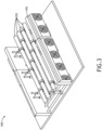
- the cooling system may feature a combination of supply and return pipes for both liquid and air cooling, an active liquid-to-air heat exchanger with integrated fans, and an optional passive liquid-to-air heat exchanger.
- the entire assembly may be preassembled and installed under computer racks, facilitating rapid deployment and significantly reducing the overall build time of data centers. By incorporating both cooling methods within the same infrastructure, this solution maximizes cooling efficiency and simplifies data center maintenance and expansion.
- the cooling system 100 includes one or more liquid pumps 206 (e.g., FIG. 2 ) integrated within the support structure.
- these liquid pumps 206 may be configured to supply liquid to manifolds 110 within individual racks of the rack system 102, enhancing the overall efficiency and reducing the need for additional external pumping infrastructure of the system 100. It is noted herein that this integration may help to simplify the installation process and minimize the required space for additional cooling equipment.
- the rack system 102 may be configured to accommodate a plurality of other equipment such as, but not limited to, one or more liquid pumps 206, one or more liquid pumps 206 integrated with the plurality of heat exchangers 106, and/or one or more auxiliary racks.
- the one or more liquid pumps 206 may be integrated within the support structure.
- the liquid pumps 206 may be configured to supply liquid to the manifolds 110 within the individual racks of the rack system 102, enhancing the overall efficiency and reducing the need for additional external pumping infrastructure of the system 100. It is noted herein that this integration may help to simplify the installation process and minimize the required space for additional cooling equipment.
- the cooling system 100 includes various configurations of heat exchangers 106 to suit specific cooling requirements.
- the system 100 may include configurations such as passive-passive, active-passive, and active-active heat exchangers 106.
- the primary heat exchanger 106a which may be passive, may include only heat exchanger coils. This flexibility allows the system 100 to adapt to varying heat loads, providing optimal cooling performance based on the specific needs of the data center 101.
- the term “hot aisle” and “cold aisle” may refer to distinct temperature-controlled zones within the data center which help manage airflow and cooling efficiency.
- the "cold aisle” may be defined as the area where the temperature is maintained at a lower range to supply cooled air to the front of the rack system 102.
- the cold aisle temperature may be maintained at a temperature below, e.g., 25 degrees Celsius, with an ideal operating range between 18 degrees Celsius and, e.g., 22 degrees Celsius. These are merely examples so that the temperature may vary.
- the cold aisle may be slightly colder than the hot aisle.
- the hot aisle may refer to the area where the temperature is higher due to the expulsion of warm air from the rear portion of the rack system 102.
- the hot aisle temperature may range between, e.g., 30 degrees Celsius and, e.g., 45 degrees Celsius, depending on the specific cooling needs and the configuration of the data center.
- These temperature ranges for the hot and cold aisles are exemplary and may vary based on specific environmental conditions, equipment requirements, and data center design.
- the cooling system 100 is designed to accommodate these temperature ranges, ensuring reliable and efficient operation of the equipment housed within the rack system 102.
- the passive heat exchanger may be omitted. This omission may further simplify the system 100 and reduce installation time and costs, without compromising the overall cooling efficiency for certain applications.
- the cooling system 100 may include a liquid distribution sub-system 104 which may include one or more liquid distribution manifolds 110.
- a liquid distribution sub-system 104 may include one or more liquid distribution manifolds 110.
- at least one of the one or more manifolds 110 may be configured to supply the plurality of heat exchangers 106 directly, while at least another manifold of the one or more manifolds 110 may be configured to supply to the manifolds 110 within individual racks of the rack system 102.
- Each underfloor manifold 110 may be designed to include one or more pipes 302 (e.g., supply pipes 502 and return pipes 504, as shown in FIG. 5 ) equipped with the necessary framework to regulate at least one of liquid flow, pressure, or temperature.
- the secondary heat exchanger 106b may be configured as a passive counterpart, comprised solely of a heat exchanger coil.
- the passive heat exchanger 106 may be omitted when additional heat transfer capacity is unnecessary. It is noted herein that various combinations of primary and secondary heat exchangers 106 are feasible, offering adaptability to varying heat loads. Combinations may include, but are not limited to, passive-passive, active-passive, and/or configurations featuring one active and one passive heat exchanger.
- the plurality of heat exchangers 106 and corresponding distribution may include, but are not limited to, any specific cooling technology such as chilled water systems and/or direction expansion through a refrigerant pipeline.
- the raised floor portions may significantly enhance the efficiency of the cooling system 100.
- the raised floor may allow for effective routing of both liquid and air-cooling pipes, and the integration of air grilles 202 to ensure optimal airflow management.
- Cold air may be directed towards the front of individual racks within the rack system 102 through the air grilles 202, while hot air is extracted from the rear, ensuring a consistent and efficient cooling cycle.
- air deflectors 204 may be installed to direct airflow more precisely, based on the layout of the data center 101.
- FIG. 5 showcases a configuration, of the system 100, employing a plurality of heat exchangers 106 that are connected to the liquid distribution manifold 110 in a parallel arrangement.
- the one or more return pipes 504 may include one or more monitoring devices 508 configured to regulate at least one of a liquid flow, pressure, or temperature.
- the one or more monitoring devices 508 may include one or more flow meters used to measure the rate of fluid return, providing data to help balance the system 100.
- the one or more monitoring devices 508 may further include one or more check valves used to prevent backflow, ensuring that the cooling fluid moves in the correct direction through the one or more return pipes 504.
- the one or more monitoring devices 508 may further include one or more temperature and pressure sensors used to continuously monitor conditions within the one or more return pipes 504, ensuring that the system 100 operates within safe and efficient parameters.
- FIG. 6 showcases a configuration, of the system 100, employing a plurality of heat exchangers 106 that are connected to the liquid distribution manifold 110 in a series arrangement.
- the connection type may be determined by the specific operational conditions faced in the system 100.
- the series configuration may maximize the heat transfer efficiency by allowing the cooling fluid to progressively cool as it flows through both heat exchangers 106.
- the series arrangement is ideal for situations where a higher degree of cooling is required, or where the cooling load is uneven and needs to be managed sequentially.
- the angles and bends in the one or more supply and return pipes 502 and 504, respectively, are calculated to minimize turbulence and maintain steady flow rates, which is critical for ensuring consistent cooling performance.
- the cooling system 100 presents a unique approach by combining cooling equipment and infrastructure, primarily the liquid coolant pipes, within a single unified assembly. This design helps to streamline manufacturing and installation, significantly reducing both time and space requirements. In comparison to traditional cooling systems, it drastically cuts down installation time, resulting in reduced data center build times and enhanced space utilization. This ultimately translates to more available space for individual computer racks of the rack system 102 or the possibility of downsizing data center facilities while maintaining optimal cooling performance.
Landscapes
- Engineering & Computer Science (AREA)
- Microelectronics & Electronic Packaging (AREA)
- Physics & Mathematics (AREA)
- Thermal Sciences (AREA)
- Computer Hardware Design (AREA)
- General Engineering & Computer Science (AREA)
- Cooling Or The Like Of Electrical Apparatus (AREA)
Applications Claiming Priority (2)
| Application Number | Priority Date | Filing Date | Title |
|---|---|---|---|
| US202363539262P | 2023-09-19 | 2023-09-19 | |
| US18/823,364 US20250098114A1 (en) | 2023-09-19 | 2024-09-03 | Cooling assembly for high power density computer racks |
Publications (1)
| Publication Number | Publication Date |
|---|---|
| EP4535948A1 true EP4535948A1 (de) | 2025-04-09 |
Family
ID=92762114
Family Applications (1)
| Application Number | Title | Priority Date | Filing Date |
|---|---|---|---|
| EP24199616.4A Pending EP4535948A1 (de) | 2023-09-19 | 2024-09-10 | Kühlanordnung für computerracks mit hoher leistungsdichte |
Country Status (3)
| Country | Link |
|---|---|
| US (1) | US20250098114A1 (de) |
| EP (1) | EP4535948A1 (de) |
| CN (1) | CN119677030A (de) |
Families Citing this family (1)
| Publication number | Priority date | Publication date | Assignee | Title |
|---|---|---|---|---|
| US20250247989A1 (en) * | 2024-01-26 | 2025-07-31 | Dell Products L.P. | Computing rack architecture system and method |
Citations (3)
| Publication number | Priority date | Publication date | Assignee | Title |
|---|---|---|---|---|
| GB2436669A (en) * | 2006-03-08 | 2007-10-03 | Cannon Technologies Ltd | Heat exchanger for a rackmount cabinet used in a raised floor installation |
| US20090056910A1 (en) * | 2007-08-30 | 2009-03-05 | Paul Mallia | Fluid cooled cabinet for electronic equipment |
| US20120024501A1 (en) * | 2010-07-28 | 2012-02-02 | International Business Machines Corporation | Thermoelectric-enhanced, liquid-cooling apparatus and method for facilitating dissipation of heat |
-
2024
- 2024-09-03 US US18/823,364 patent/US20250098114A1/en active Pending
- 2024-09-10 EP EP24199616.4A patent/EP4535948A1/de active Pending
- 2024-09-18 CN CN202411297736.XA patent/CN119677030A/zh active Pending
Patent Citations (3)
| Publication number | Priority date | Publication date | Assignee | Title |
|---|---|---|---|---|
| GB2436669A (en) * | 2006-03-08 | 2007-10-03 | Cannon Technologies Ltd | Heat exchanger for a rackmount cabinet used in a raised floor installation |
| US20090056910A1 (en) * | 2007-08-30 | 2009-03-05 | Paul Mallia | Fluid cooled cabinet for electronic equipment |
| US20120024501A1 (en) * | 2010-07-28 | 2012-02-02 | International Business Machines Corporation | Thermoelectric-enhanced, liquid-cooling apparatus and method for facilitating dissipation of heat |
Also Published As
| Publication number | Publication date |
|---|---|
| CN119677030A (zh) | 2025-03-21 |
| US20250098114A1 (en) | 2025-03-20 |
Similar Documents
| Publication | Publication Date | Title |
|---|---|---|
| US12041758B2 (en) | Cooling system for a data center that includes an offset cooling technology | |
| US8118084B2 (en) | Heat exchanger and method for use in precision cooling systems | |
| US7810341B2 (en) | Redundant upgradeable, modular data center cooling apparatus | |
| CA2680884C (en) | Air-based cooling for data center rack | |
| US20090262495A1 (en) | High efficiency heat removal system for rack mounted computer equipment | |
| US11212942B2 (en) | Cooling arrangement for autonomous cooling of a rack | |
| EP3829279B1 (de) | Kühlanordnung zur autonomen kühlung eines schranks | |
| US9605855B2 (en) | Air conditioning system using outside air | |
| EP4535948A1 (de) | Kühlanordnung für computerracks mit hoher leistungsdichte | |
| JP5579518B2 (ja) | 空調システム | |
| US11197395B1 (en) | Multi-layer data center cooling infrastructure | |
| US20250275101A1 (en) | Zero-u coolant distribution unit | |
| US20240284639A1 (en) | Zero-U Coolant Distribution Unit | |
| CN114390851B (zh) | 一种机房散热降温系统、机房 | |
| CN204806579U (zh) | 一种高效模块化空调系统 | |
| CN213273001U (zh) | 机房散热降温设备、机房 | |
| CN213273002U (zh) | 一种机房散热降温系统、机房 | |
| US11886258B2 (en) | Hybrid heat sink for electronics cooling | |
| CN219371118U (zh) | 一种紧凑型液冷机组及储能集装箱 | |
| CN114390853B (zh) | 一种机房空调系统、机房 | |
| CN114390852B (zh) | 一种机房散热降温设备、机房 | |
| CN116014283A (zh) | 一种紧凑型液冷机组及储能集装箱 | |
| CN114390850A (zh) | 一种机房空调系统 | |
| CN206944337U (zh) | 一种节能多联式列间空调装置 | |
| CN221488191U (zh) | 基于微通道环路热管的数据中心机柜级复合冷却系统 |
Legal Events
| Date | Code | Title | Description |
|---|---|---|---|
| PUAI | Public reference made under article 153(3) epc to a published international application that has entered the european phase |
Free format text: ORIGINAL CODE: 0009012 |
|
| STAA | Information on the status of an ep patent application or granted ep patent |
Free format text: STATUS: THE APPLICATION HAS BEEN PUBLISHED |
|
| AK | Designated contracting states |
Kind code of ref document: A1 Designated state(s): AL AT BE BG CH CY CZ DE DK EE ES FI FR GB GR HR HU IE IS IT LI LT LU LV MC ME MK MT NL NO PL PT RO RS SE SI SK SM TR |
|
| STAA | Information on the status of an ep patent application or granted ep patent |
Free format text: STATUS: REQUEST FOR EXAMINATION WAS MADE |
|
| 17P | Request for examination filed |
Effective date: 20250430 |