EP4535947A1 - Charging device - Google Patents
Charging device Download PDFInfo
- Publication number
- EP4535947A1 EP4535947A1 EP23814693.0A EP23814693A EP4535947A1 EP 4535947 A1 EP4535947 A1 EP 4535947A1 EP 23814693 A EP23814693 A EP 23814693A EP 4535947 A1 EP4535947 A1 EP 4535947A1
- Authority
- EP
- European Patent Office
- Prior art keywords
- air
- charging
- chamber
- charging device
- charging module
- Prior art date
- Legal status (The legal status is an assumption and is not a legal conclusion. Google has not performed a legal analysis and makes no representation as to the accuracy of the status listed.)
- Pending
Links
Images


Classifications
-
- H—ELECTRICITY
- H02—GENERATION; CONVERSION OR DISTRIBUTION OF ELECTRIC POWER
- H02J—ELECTRIC POWER NETWORKS; CIRCUIT ARRANGEMENTS OR SYSTEMS FOR SUPPLYING OR DISTRIBUTING ELECTRIC POWER; SYSTEMS FOR STORING ELECTRIC ENERGY
- H02J7/00—Circuit arrangements for charging or discharging batteries or for supplying loads from batteries
- H02J7/70—Circuit arrangements for charging or discharging batteries or for supplying loads from batteries characterised by the mechanical construction
-
- B—PERFORMING OPERATIONS; TRANSPORTING
- B60—VEHICLES IN GENERAL
- B60L—PROPULSION OF ELECTRICALLY-PROPELLED VEHICLES; SUPPLYING ELECTRIC POWER FOR AUXILIARY EQUIPMENT OF ELECTRICALLY-PROPELLED VEHICLES; ELECTRODYNAMIC BRAKE SYSTEMS FOR VEHICLES IN GENERAL; MAGNETIC SUSPENSION OR LEVITATION FOR VEHICLES; MONITORING OPERATING VARIABLES OF ELECTRICALLY-PROPELLED VEHICLES; ELECTRIC SAFETY DEVICES FOR ELECTRICALLY-PROPELLED VEHICLES
- B60L53/00—Methods of charging batteries, specially adapted for electric vehicles; Charging stations or on-board charging equipment therefor; Exchange of energy storage elements in electric vehicles
- B60L53/30—Constructional details of charging stations
- B60L53/302—Cooling of charging equipment
-
- B—PERFORMING OPERATIONS; TRANSPORTING
- B60—VEHICLES IN GENERAL
- B60L—PROPULSION OF ELECTRICALLY-PROPELLED VEHICLES; SUPPLYING ELECTRIC POWER FOR AUXILIARY EQUIPMENT OF ELECTRICALLY-PROPELLED VEHICLES; ELECTRODYNAMIC BRAKE SYSTEMS FOR VEHICLES IN GENERAL; MAGNETIC SUSPENSION OR LEVITATION FOR VEHICLES; MONITORING OPERATING VARIABLES OF ELECTRICALLY-PROPELLED VEHICLES; ELECTRIC SAFETY DEVICES FOR ELECTRICALLY-PROPELLED VEHICLES
- B60L53/00—Methods of charging batteries, specially adapted for electric vehicles; Charging stations or on-board charging equipment therefor; Exchange of energy storage elements in electric vehicles
- B60L53/30—Constructional details of charging stations
- B60L53/31—Charging columns specially adapted for electric vehicles
-
- H—ELECTRICITY
- H05—ELECTRIC TECHNIQUES NOT OTHERWISE PROVIDED FOR
- H05K—PRINTED CIRCUITS; CASINGS OR CONSTRUCTIONAL DETAILS OF ELECTRIC APPARATUS; MANUFACTURE OF ASSEMBLAGES OF ELECTRICAL COMPONENTS
- H05K7/00—Constructional details common to different types of electric apparatus
- H05K7/20—Modifications to facilitate cooling, ventilating, or heating
- H05K7/20536—Modifications to facilitate cooling, ventilating, or heating for racks or cabinets of standardised dimensions, e.g. electronic racks for aircraft or telecommunication equipment
- H05K7/20554—Forced ventilation of a gaseous coolant
- H05K7/20572—Forced ventilation of a gaseous coolant within cabinets for removing heat from sub-racks, e.g. plenum
-
- H—ELECTRICITY
- H05—ELECTRIC TECHNIQUES NOT OTHERWISE PROVIDED FOR
- H05K—PRINTED CIRCUITS; CASINGS OR CONSTRUCTIONAL DETAILS OF ELECTRIC APPARATUS; MANUFACTURE OF ASSEMBLAGES OF ELECTRICAL COMPONENTS
- H05K7/00—Constructional details common to different types of electric apparatus
- H05K7/20—Modifications to facilitate cooling, ventilating, or heating
- H05K7/2089—Modifications to facilitate cooling, ventilating, or heating for power electronics, e.g. for inverters for controlling motor
- H05K7/20909—Forced ventilation, e.g. on heat dissipaters coupled to components
-
- Y—GENERAL TAGGING OF NEW TECHNOLOGICAL DEVELOPMENTS; GENERAL TAGGING OF CROSS-SECTIONAL TECHNOLOGIES SPANNING OVER SEVERAL SECTIONS OF THE IPC; TECHNICAL SUBJECTS COVERED BY FORMER USPC CROSS-REFERENCE ART COLLECTIONS [XRACs] AND DIGESTS
- Y02—TECHNOLOGIES OR APPLICATIONS FOR MITIGATION OR ADAPTATION AGAINST CLIMATE CHANGE
- Y02T—CLIMATE CHANGE MITIGATION TECHNOLOGIES RELATED TO TRANSPORTATION
- Y02T10/00—Road transport of goods or passengers
- Y02T10/60—Other road transportation technologies with climate change mitigation effect
- Y02T10/70—Energy storage systems for electromobility, e.g. batteries
Definitions
- the present application relates to the technical field of charging devices, and in particular to a charging device.
- a charging module which is an important component of a charging device, generates a large amount of heat in operation, causing an increased overall heat of the charging device.
- the adopted method is to install a cooling air blower to directly dissipate heat from the inside of the charging module, which increases costs. Meanwhile, it is difficult to achieve a high level of protection for the charging module, which may cause a shortened service life.
- the cooling air blower is often located in the high-temperature zone of a cooling air duct, such as at an air outlet, causing high energy consumption, a short service life, and a poor actual cooling effect of the cooling air blower.
- An object of the present application is to provide a charging device, which is direct to ensure the service life of the air blower while also improve the heat dissipation efficiency and use safety of the charging module, thereby providing a reliable use of the charging device.
- a charging device including:
- a gap is provided between the air blower and the charging module for cold air flowing there through.
- the charging module includes a housing, and a sealed chamber for accommodating a conversion device is provided in the housing.
- a heat dissipation device is provided on an exterior of the housing.
- the housing is provided with multiple side surfaces
- the heat dissipation device includes a radiating fin
- the radiation fin is located on at least one side surface.
- the air inlet is aligned with the radiating fin.
- the charging device further includes an air baffle fixed inside the accommodation chamber and extending towards the air outlet to guide air inside the accommodation chamber to the air outlet.
- the case includes a front plate, a back plate, and a top plate connecting the front plate and the back plate, and the front plate and the back plate are arranged in opposite, where the air inlet is formed on the front plate and the air outlet is formed on at least one of the back plate and the top plate, or the air inlet is formed on the back plate and the air outlet is formed on at least one of the front plate and the top plate.
- the charging module includes multiple charging modules, which are arranged in array along a height direction and a width direction of the case, respectively.
- At least two columns of the multiple charging modules are staggered, and/or at least two rows of the multiple charging modules are staggered.
- a partition plate is further arranged inside the case, and the partition plate partitions the accommodation chamber to form a first chamber and at least one second chamber, and the charging module is located in the first chamber and the second chamber is configured to accommodate an electrical component.
- the partition plate is provided with an air vent to allow a part of the air to enter the second chamber for heat dissipation of the electrical component.
- the second chamber is arranged above the first chamber, or
- the charging module is arranged between the air inlet and the air outlet and the air blower is located close to the air inlet, which is positioned in a low-temperature area, avoiding the hot air backflow from affecting the operation of the air blower.
- the air blower Under the action of the air blower, a cold air outside the device may be drawn into the accommodation chamber through the air inlet. Due to the pressure difference, the cold air flows over the surface of the charging module and flows towards the air outlet and is discharged outside of the device through the air outlet.
- the cold air absorbs the heat generated by the charging module and becomes the heated air, reducing the overall heat of the case, lowering the temperature inside the accommodation chamber and the temperature of the charging module, which ensures both the service life of the air blower and enhances the heat dissipation efficiency and the uses safety of the charging module, ensuring a reliable use of the charging device.
- 10 case 15 partition plate, 10a accommodation chamber, 16a first chamber, 10b air inlet, 16b second chamber, 10c air outlet, 20 charging unit, 11 front plate, 21 charging module, 12 back plate, 21a housing, 13 top plate, 21b radiating fin, 14 air baffle, 30 air blower, 14a guide air duct.
- the cold air absorbs the heat generated by the charging module in a manner of heat exchanging and becomes heated air, reducing the overall heat of the case 10 and lowering the temperature inside the accommodation chamber 10a and the temperature of the charging module 21, which not only ensures the service life of the air blower 30 but also enhances the heat dissipation efficiency and the use safety of the charging module 21, providing a reliable use of the charging device.
- the case 10 has a high protection level, and/or the charging unit 20 has a high protection level, ensuring the charging module 21 to be in a well-sealed environment, thus preventing a potential malfunction or even failure caused by adverse conditions such as strong wind, heavy rain, or high temperature.
- the charging unit 20 is used to charge electrical devices. Specifically, the charging unit 20 is directly or indirectly connected to electrical devices in order to charging them.
- the charging module 21 of the charging unit 20 is a power conversion module for converting the power for inputting the charging module 21 into the power required by the electrical devices, realizing the charging process for the electrical devices.
- Multiple charging modules 21 can be provided, which are arranged in parallel to provide the required power for the electrical devices, making it suitable for small charging locations such as charging posts as well as for large charging locations such as large-scale charging stations.
- the charging unit 20 can be provided with multiple charging modules 21 to achieve a power stack, so that, during the charging process, different numbers of charging modules 21 can be turned on based on the power demand during charging, enabling the charging device to charge different electrical devices, which makes the usage scenarios of charging devices diverse and adaptable .
- the charging device may be a charging post, a charging station and so on.
- a gap is provided between the air blower 30 and the charging module 21 for the cold air flowing there through. That is, sufficient cold air can be filled between the air blower 30 and the charging module 21. With this configuration, it facilitates of extending the duration of cold air inside the accommodation chamber 10a and increasing the amount of cold air inside the accommodation chamber 10a, making cold air sufficiently contact the charging module 21 for heat exchanging, thereby the heat dissipation efficiency of the charging module 21 is improved.
- the main heat source in the charging device is the charging module 21, which generates a significant amount of heat during operation, causing an increase of the overall temperature of the device.
- the charging device needs to be timely cooled. Therefore, in the embodiment, a heat dissipation device is provided on the exterior of the housing 21a to implement an independent heat dissipation for the charging module 21.
- the housing 21a is provided with multiple side surfaces, and the heat dissipation device is a radiating fin 21b located on at least one side surface. It can be understood that the housing 21a is enclosed by multiple side surfaces.
- the heat dissipation device is the radiating fin 21b
- multiple radiating fins 21b may be provided, which are arranged on one side surface, or arranged on opposite side surfaces, or arranged on each side surface, so as to ensure a relatively large effective contact area between cold air drawn in through the air inlet 10b and the multiple radiating fins 21b, thereby greatly improving the heat dissipation efficiency of the charging module 21 and ensuring the reliable use of the charging module 21.
- the present application is not limited to this, where, in other embodiments, the heat dissipation device may be in the form of slots formed on the surface of the housing 21a.
- the air inlet 10b and the multiple radiating fins 21b are aligned.
- cold air can flow directly towards the multiple radiating fins 21b and disperse, so as to concentrate most of the cold air to act on the multiple radiating fins 21b, which shortens the path for cold air to the charging module 21 and increases the heat dissipation rate of the charging module 21.
- the charging device in order to direct the airflow inside the accommodation chamber 10a towards the air outlet 10c, the charging device further includes an air baffle 14, which is fixed inside the accommodation chamber 10a and extending towards the air outlet 10c, so as to guide the air inside the accommodation chamber 10a towards the air outlet 10c.
- the charging device can guide the air after being in heat exchanging with the charging module 21 to concentrate the air after being in heat exchanging with the charging module 21 at the air outlet 10c to be further discharged when more external cold air is drawn into the accommodation chamber 10a by the air blower 30, thereby lowering the temperature inside the accommodation chamber 10a.
- At least one air baffle 14 is provided, and forms a guide air duct 14a together with the case 10 and one side of the charging module 21 away from the air inlet 10b.
- the guide air duct 14a is in communication with the air outlet 10c, that is, a side wall of the case 10, the side of the charging module 21 away from the air inlet 10b, and the air baffle 14 enclose to form a guide air duct 14a, which is conducive to concentrating the air after being heat exchanged at the air outlet 10c, facilitating the discharge of the heat-exchanged air, and improving the heat dissipation efficiency.
- Multiple air baffles 14 may be provided to gather the air after being heat exchanged from various directions inside the case 10.
- the multiple air baffles 14 may be in an integrated structure, and their specific form can be configured to match with the location of the air outlet 10c on the case 10.
- the multiple air baffles 14 may be of a detachable structure, for example, being secured through splicing, snap fitting, and other connection methods for easy disassembly and assembly.
- One end of the air baffle 14 is connected to the side wall of the case 10 and is located close to the air outlet 10c.
- the other end can be directly suspended above/below the side of the charging module 21 away from the air inlet 10b, or on the side portion at the side the charging module 21 away from the air inlet 10b, or connected to the other side wall of the case 10, so as to ensure the air flowing through the charging module 21 to flow towards the air outlet 10c.
- the air baffle 14 is inclined towards the air outlet 10c to guide the air flowing towards the outlet 10c. It can be understood that, by inclining the air baffle 14 towards the air outlet 10c, i.e., based on the position relationship between the side of the charging module 21 away from the air inlet 10b and the air outlet 10c, the rear end of the air baffle 14 can be gradually expanded or tapered towards the direction away from the air outlet 10c, which can further reduce the range of air escape, facilitate the concentration of heat exchange air, improve the flowing rate of the air towards the direction of the air outlet 10c, and improve heat dissipation efficiency.
- the air baffle 14 may be a straight plate with a simple structure and easy disassembly.
- the air baffle 14 may also be an arc-shaped plate, which is designed according to the location of the charging module 21 and the air outlet 10c to match the direction of air flow with the arc-shaped structure of the air baffle 14, so as to better guide the heat-exchanged air to flow to the air outlet 10c and further improve the guiding effect of the air baffle 14.
- the case 10 includes a front plate 11 and a back plate 12 that are arranged in opposite, and a top plate 13 connecting the front plate 11 and the back plate 12.
- the air inlet 10b is formed on the front plate 11, and the air outlet 10c is formed on at least one of the back plate 12 and the top plate 13.
- the air inlet 10b is formed on the back plate 12, and the air outlet 10c is formed on at least one of the front plate 11 and the top plate 13. It can be understood that, for example, if the air inlet 10b is formed on the front plate 11, when only one air outlet 10c is provided, the air outlet 10c may be formed in the back plate 12 close to the top plate 13, or in the top plate 13 close to the back plate 12.
- the air outlets 10c may be formed on the back plate 12 close to the top plate 13 and in the top plate 13 close to the back plate 12, respectively, which ensures the heat exchanged air to rise after passing through the charging module 21 and is then discharged through the air outlet 10c with a low resistance and a high discharging rate, thereby improving the heat dissipation efficiency.
- the present application is not limited to this, and in other embodiments, the air outlet 10c may be formed in the middle of the back plate 12 or at the bottom of the back plate 12, which can shorten the distance of the air flowing through part of the charging module 21 flowing to the air outlet 10c.
- the air outlet 10c may be formed in the front plate 11 close to the top plate 13 or in the top plate 13 close to the front plate 11.
- the air outlet 10c may be formed in the front plate 11 close to the top plate 13 and in the top plate 13 close to the front plate 11, respectively, which ensures the heat-exchanged air to rise after passing through the charging module 21 and be then discharged through the air outlet 10c with a low resistance and a high discharging rate, thereby improving the heat dissipation efficiency.
- the air outlet 10c may be formed in the middle of the front plate 11 or at the bottom of the front plate 11, which can shorten the distance of the air flowing through part of the charging module 21 flowing to the air outlet 10c.
- multiple charging modules 21 are provided, which are arranged in array along the height and width directions of the case 10. That is, according to the size of the case 10 and power requirements, the multiple charging modules 21 may be arranged in a single column, single row, or multiple rows and columns. With the superposition of the multiple charging modules 21, i.e., different numbers of charging modules 21 connected in parallel, the required power of the electrical equipment can be provided, thereby completing charging and enhancing the adaptability of the charging device, and making it suitable for various charging locations.
- At least two rows of the charging modules 21 are staggered, and/or at least two rows of charging modules 21 are staggered. With this configuration, it can extend the retention duration of cold air inside the accommodation chamber 10a, ensuring each charging module 21 inside the accommodation chamber 10a to come into full contact with the cold air, thereby implementing the heat exchanging between the cold air and the radiating fins 21b on the charging module 21, and the heat dissipation efficiency of the charging modules 21 is improved and the use reliability and the use safety of the charging device are improved.
- each charging module 21 when the opposite surfaces of each charging module 21 are provided with the aforementioned heat dissipation device, such as radiating fins 21b, taking the height direction of the case 10 as a reference, as shown in FIG. 1 and FIG. 2 , the charging module 21 are spaced apart along the height direction of the case 10, and the radiating fins 21b are arranged on the upper and lower surfaces of the charging module 21, respectively.
- multiple air inlets 10b may be provided, which are all aligned with the radiating fins 21b of the charging module 21.
- only a part of air inlets 10b are aligned with the radiating fins 21b of a part of charging module 21.
Landscapes
- Engineering & Computer Science (AREA)
- Power Engineering (AREA)
- Microelectronics & Electronic Packaging (AREA)
- Transportation (AREA)
- Mechanical Engineering (AREA)
- Physics & Mathematics (AREA)
- Thermal Sciences (AREA)
- Aviation & Aerospace Engineering (AREA)
- Cooling Or The Like Of Electrical Apparatus (AREA)
- Charge And Discharge Circuits For Batteries Or The Like (AREA)
Abstract
Description
- The present application claims the priority to
Chinese Patent Application No. 202221344844.4, titled "CHARGING DEVICE", filed with the China National Intellectual Property Administration on May 30, 2022 - The present application relates to the technical field of charging devices, and in particular to a charging device.
- A charging module, which is an important component of a charging device, generates a large amount of heat in operation, causing an increased overall heat of the charging device. In order to ensure the reliable operation of the components, it is necessary to timely cool the charging device. Currently, the adopted method is to install a cooling air blower to directly dissipate heat from the inside of the charging module, which increases costs. Meanwhile, it is difficult to achieve a high level of protection for the charging module, which may cause a shortened service life. Moreover, the cooling air blower is often located in the high-temperature zone of a cooling air duct, such as at an air outlet, causing high energy consumption, a short service life, and a poor actual cooling effect of the cooling air blower.
- An object of the present application is to provide a charging device, which is direct to ensure the service life of the air blower while also improve the heat dissipation efficiency and use safety of the charging module, thereby providing a reliable use of the charging device.
- To achieve the object, a charging device is provided in the present application, including:
- a case, which is provided with an accommodation chamber, an air inlet and an air outlet that are in communication with the accommodation chamber;
- a charging unit, which is located in the accommodation chamber and includes a charging module for battery charging; and
- an air blower, which is positioned at the air inlet to introduce cold air to flow into the accommodation chamber through the air inlet, flow through the charging module and then be discharged through the air outlet.
- In an embodiment, a gap is provided between the air blower and the charging module for cold air flowing there through.
- In an embodiment, the charging module includes a housing, and a sealed chamber for accommodating a conversion device is provided in the housing.
- In an embodiment, a heat dissipation device is provided on an exterior of the housing.
- In an embodiment, the housing is provided with multiple side surfaces, the heat dissipation device includes a radiating fin, and the radiation fin is located on at least one side surface.
- In an embodiment, the air inlet is aligned with the radiating fin.
- In an embodiment, the charging device further includes an air baffle fixed inside the accommodation chamber and extending towards the air outlet to guide air inside the accommodation chamber to the air outlet.
- In an embodiment, the case includes a front plate, a back plate, and a top plate connecting the front plate and the back plate, and the front plate and the back plate are arranged in opposite, where the air inlet is formed on the front plate and the air outlet is formed on at least one of the back plate and the top plate, or the air inlet is formed on the back plate and the air outlet is formed on at least one of the front plate and the top plate.
- In an embodiment, the charging module includes multiple charging modules, which are arranged in array along a height direction and a width direction of the case, respectively.
- In an embodiment, at least two columns of the multiple charging modules are staggered, and/or at least two rows of the multiple charging modules are staggered.
- In an embodiment, a partition plate is further arranged inside the case, and the partition plate partitions the accommodation chamber to form a first chamber and at least one second chamber, and the charging module is located in the first chamber and the second chamber is configured to accommodate an electrical component.
- In an embodiment, the partition plate is provided with an air vent to allow a part of the air to enter the second chamber for heat dissipation of the electrical component.
- In an embodiment, the second chamber is arranged above the first chamber, or
- the second chamber is arranged below the first chamber, or
- the second chamber is arranged on a side of the first chamber, or
- at least two second chambers are provided, which are arranged around the first chamber.
- In the present application, the charging module is arranged between the air inlet and the air outlet and the air blower is located close to the air inlet, which is positioned in a low-temperature area, avoiding the hot air backflow from affecting the operation of the air blower. Under the action of the air blower, a cold air outside the device may be drawn into the accommodation chamber through the air inlet. Due to the pressure difference, the cold air flows over the surface of the charging module and flows towards the air outlet and is discharged outside of the device through the air outlet. During this process, the cold air absorbs the heat generated by the charging module and becomes the heated air, reducing the overall heat of the case, lowering the temperature inside the accommodation chamber and the temperature of the charging module, which ensures both the service life of the air blower and enhances the heat dissipation efficiency and the uses safety of the charging module, ensuring a reliable use of the charging device.
- In order to clearly illustrate embodiments of the present application or technical solutions in the conventional technology, a brief introduction will be made to the accompanying drawings in the embodiments or conventional technology. Apparently, the accompanying drawings in the following description are merely some embodiments of the present application. For those skilled in the art, other accompanying drawings can be also obtained based on these drawings without paying a creative work.
-
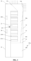
FIG. 1 is a schematic structural view of a charging device according to an embodiment of the present application; -
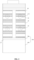
FIG. 2 is a left view of the charging device inFIG. 1 ; -
FIG. 3 is a schematic structural view of a charging device according to another embodiment of the present application ; -
FIG. 4 is a left view of the charging device inFIG. 3 ; and -
FIG. 5 is a schematic structural view of a charging module. -
10 case, 15 partition plate, 10a accommodation chamber, 16a first chamber, 10b air inlet, 16b second chamber, 10c air outlet, 20 charging unit, 11 front plate, 21 charging module, 12 back plate, 21a housing, 13 top plate, 21b radiating fin, 14 air baffle, 30 air blower, 14a guide air duct. - The implementation, functional characteristics, and advantages of the present application will be further explained in conjunction with embodiments and with reference to the accompanying drawings.
- The following will provide a clear and complete description to the technical solution in the embodiments of the present application, in conjunction with the accompanying drawings. Apparently, the described embodiments are merely a part of the embodiments of the present application, not all of them. Based on the embodiments in the present application, all other embodiments obtained by those skilled in the art without paying a creative work will fall within the scope of protection of the present application.
- In the present application, unless otherwise expressly specified and limited, terms such as "connection" and "fixing" should be broadly understood. For example, "fixing" can be a fixed connection, a detachable connection, or being integral, and it can be a mechanical connection or an electrical connection, and it can be directly connected or indirectly connected through an intermediate medium, and it can be an internal connection of two components or the interaction relationship between two components, unless otherwise clearly limited. For those skilled in the art, the specific meanings of the above terms in the present application can be understood according to the specific circumstances.
- In addition, in the present application, if there is a description of "first," "second," etc., it is only used for the purpose of description and cannot be understood as indicating or implying the relative importance or implying the quantity of the indicated technical features. Therefore, the limitation of "first," "second," etc., can explicitly or implicitly include at least one of that feature. Furthermore, the technical solutions between different embodiments can be combined, but it must be based on what those skilled in the art in this field can achieve. When the combination of technical solutions contradicts each other or cannot be realized, it should be considered that the combination of these technical solutions does not exist and is not within the scope of protection required by the present application.
- A charging device is provided in the present application.
- Referring to
FIG. 1 to FIG. 5 , in the embodiments of the present application, the charging device includes acase 10, acharging unit 20, and anair blower 30. Thecase 10 is provided with anaccommodation chamber 10a and anair inlet 10b and anair outlet 10c that are in communication with theaccommodation chamber 10a. Thecharging unit 20 is located in theaccommodation chamber 10a and includes acharging module 21 for battery charging. Theair blower 30 is positioned at theair inlet 10b to introduce cold air to flow into theaccommodation chamber 10a through theair inlet 10b, then flow through thecharging module 21 and be discharged through theair outlet 10c. It can be understood that theair blower 30 is located in a low-temperature area, i.e., at theair inlet 10b, to prevent a hot air from flowing back so as to affect the operation of theair blower 30. Thecharging module 21 is positioned between theair inlet 10b and theair outlet 10c. Under the action of theair blower 30, cold air outside the device is drawn into theaccommodation chamber 10a through theair inlet 10b, creating a pressure differential that causes the cold air to flow over the surface of thecharging module 21 and flow towards theair outlet 10c and then be discharged to the outside of the device. During this process, the cold air absorbs the heat generated by the charging module in a manner of heat exchanging and becomes heated air, reducing the overall heat of thecase 10 and lowering the temperature inside theaccommodation chamber 10a and the temperature of the chargingmodule 21, which not only ensures the service life of theair blower 30 but also enhances the heat dissipation efficiency and the use safety of the chargingmodule 21, providing a reliable use of the charging device. - The
case 10 has a high protection level, and/or the chargingunit 20 has a high protection level, ensuring the chargingmodule 21 to be in a well-sealed environment, thus preventing a potential malfunction or even failure caused by adverse conditions such as strong wind, heavy rain, or high temperature. - The
air inlet 10b and theair outlet 10c are provided on thecase 10. Multiple theair inlets 10b may be provided at the top or on the side of thecase 10 and in communicating with theair outlet 10c through theaccommodation chamber 10a. In that case,multiple air outlets 10 may be provided on the side or at the top as long as it ensures that the air flowing in through theair inlet 10b can flow over the chargingmodule 21 and be discharged through theair outlet 10c, which is not limited here. - The
air blower 30 is located at theair inlet 10b, at a cold end of the airflow path formed by the communication between theair inlet 10b and theair outlet 10c. In this case, the temperature of the environment where theair blower 30 is located is lower than that at theair outlet 10c, ensuring the service life of theair blower 30 and avoiding the service life of theair blower 30 from being shortened by a high environmental temperature or a hot air backflow. Theair blower 30 can be acentrifugal air blower 30, a fan, or any device capable of introducing cold air into thecase 10, and multiple air blowers can be provided according to requirements. - The charging
unit 20 is used to charge electrical devices. Specifically, the chargingunit 20 is directly or indirectly connected to electrical devices in order to charging them. In this embodiment, the chargingmodule 21 of the chargingunit 20 is a power conversion module for converting the power for inputting the chargingmodule 21 into the power required by the electrical devices, realizing the charging process for the electrical devices.Multiple charging modules 21 can be provided, which are arranged in parallel to provide the required power for the electrical devices, making it suitable for small charging locations such as charging posts as well as for large charging locations such as large-scale charging stations. That is, the chargingunit 20 can be provided with multiple chargingmodules 21 to achieve a power stack, so that, during the charging process, different numbers of chargingmodules 21 can be turned on based on the power demand during charging, enabling the charging device to charge different electrical devices, which makes the usage scenarios of charging devices diverse and adaptable . - The charging device may be a charging post, a charging station and so on.
- In the present application, the charging
module 21 is arranged between theair inlet 10b and theair outlet 10c and theair blower 30 is located close to theair inlet 10b, which is positioned in a low-temperature area, avoiding the hot air backflow from affecting the operation of theair blower 30. Under the action of theair blower 30, cold air outside the device is drawn into theaccommodation chamber 10a through theair inlet 10b. Due to the pressure difference, cold air flows over the surface of the chargingmodule 21, flows towards theair outlet 10c and then is discharged outside of the device through theair outlet 10c. During this process, cold air absorbs the heat generated by the chargingmodule 21 and becomes heated air, reducing the overall heat of thecase 10, lowering the temperature inside theaccommodation chamber 10a and the temperature of the chargingmodule 21, which ensures the service life of theair blower 30 and improves the heat dissipation efficiency and the use safety of the chargingmodule 21, further ensuring a reliable use of the charging device. - Referring to
FIG. 1 andFIG. 3 , a gap is provided between theair blower 30 and the chargingmodule 21 for the cold air flowing there through. That is, sufficient cold air can be filled between theair blower 30 and the chargingmodule 21. With this configuration, it facilitates of extending the duration of cold air inside theaccommodation chamber 10a and increasing the amount of cold air inside theaccommodation chamber 10a, making cold air sufficiently contact the chargingmodule 21 for heat exchanging, thereby the heat dissipation efficiency of the chargingmodule 21 is improved. - Referring
FIG. 5 , in an embodiment, the chargingmodule 21 includes ahousing 21a. A sealed chamber for accommodating the conversion device is provided in thehousing 21a. With this configuration, it can ensure that the chargingmodule 21 has a high level of protection, thus avoiding a damage of the conversion device inside the chargingmodule 21 caused by an external environmental affection and improving the use reliability of the chargingmodule 21, thus reducing maintenance costs and improving the use safety of the charging device. - The main heat source in the charging device is the charging
module 21, which generates a significant amount of heat during operation, causing an increase of the overall temperature of the device. In order to ensure a normal operation of the components inside the chargingmodule 21, the charging device needs to be timely cooled. Therefore, in the embodiment, a heat dissipation device is provided on the exterior of thehousing 21a to implement an independent heat dissipation for the chargingmodule 21. Since the chargingmodule 21 itself does not have a heat dissipation module, the heat dissipation of the chargingmodule 21 is achieved merely through the cooperation of the heat dissipation device and theair blower 30 of the charging device to implement heat exchanging between the cold air and the heat dissipation device, thus the cost is low, the noise is controllable and the effect of heat dissipation is significantly improved. - Specially, in an embodiment, the
housing 21a is provided with multiple side surfaces, and the heat dissipation device is a radiatingfin 21b located on at least one side surface. It can be understood that thehousing 21a is enclosed by multiple side surfaces. In case that the heat dissipation device is the radiatingfin 21b, multiple radiatingfins 21b may be provided, which are arranged on one side surface, or arranged on opposite side surfaces, or arranged on each side surface, so as to ensure a relatively large effective contact area between cold air drawn in through theair inlet 10b and the multiple radiatingfins 21b, thereby greatly improving the heat dissipation efficiency of the chargingmodule 21 and ensuring the reliable use of the chargingmodule 21. Alternatively, the present application is not limited to this, where, in other embodiments, the heat dissipation device may be in the form of slots formed on the surface of thehousing 21a. - In addition, in an embodiment, the
air inlet 10b and the multiple radiatingfins 21b are aligned. As such, when being drawn in through theair inlet 10b by theair blower 30, cold air can flow directly towards the multiple radiatingfins 21b and disperse, so as to concentrate most of the cold air to act on themultiple radiating fins 21b, which shortens the path for cold air to the chargingmodule 21 and increases the heat dissipation rate of the chargingmodule 21. - In an embodiment, in order to direct the airflow inside the
accommodation chamber 10a towards theair outlet 10c, the charging device further includes anair baffle 14, which is fixed inside theaccommodation chamber 10a and extending towards theair outlet 10c, so as to guide the air inside theaccommodation chamber 10a towards theair outlet 10c. As such, it can guide the air after being in heat exchanging with the chargingmodule 21 to concentrate the air after being in heat exchanging with the chargingmodule 21 at theair outlet 10c to be further discharged when more external cold air is drawn into theaccommodation chamber 10a by theair blower 30, thereby lowering the temperature inside theaccommodation chamber 10a. - In addition, in an embodiment, at least one
air baffle 14 is provided, and forms aguide air duct 14a together with thecase 10 and one side of the chargingmodule 21 away from theair inlet 10b. Theguide air duct 14a is in communication with theair outlet 10c, that is, a side wall of thecase 10, the side of the chargingmodule 21 away from theair inlet 10b, and theair baffle 14 enclose to form aguide air duct 14a, which is conducive to concentrating the air after being heat exchanged at theair outlet 10c, facilitating the discharge of the heat-exchanged air, and improving the heat dissipation efficiency. Multiple air baffles 14 may be provided to gather the air after being heat exchanged from various directions inside thecase 10. The multiple air baffles 14 may be in an integrated structure, and their specific form can be configured to match with the location of theair outlet 10c on thecase 10. Alternatively, the multiple air baffles 14 may be of a detachable structure, for example, being secured through splicing, snap fitting, and other connection methods for easy disassembly and assembly. - One end of the
air baffle 14 is connected to the side wall of thecase 10 and is located close to theair outlet 10c. The other end can be directly suspended above/below the side of the chargingmodule 21 away from theair inlet 10b, or on the side portion at the side the chargingmodule 21 away from theair inlet 10b, or connected to the other side wall of thecase 10, so as to ensure the air flowing through the chargingmodule 21 to flow towards theair outlet 10c. - Specifically, in an embodiment, the
air baffle 14 is inclined towards theair outlet 10c to guide the air flowing towards theoutlet 10c. It can be understood that, by inclining theair baffle 14 towards theair outlet 10c, i.e., based on the position relationship between the side of the chargingmodule 21 away from theair inlet 10b and theair outlet 10c, the rear end of theair baffle 14 can be gradually expanded or tapered towards the direction away from theair outlet 10c, which can further reduce the range of air escape, facilitate the concentration of heat exchange air, improve the flowing rate of the air towards the direction of theair outlet 10c, and improve heat dissipation efficiency. Theair baffle 14 may be a straight plate with a simple structure and easy disassembly. Alternatively, theair baffle 14 may also be an arc-shaped plate, which is designed according to the location of the chargingmodule 21 and theair outlet 10c to match the direction of air flow with the arc-shaped structure of theair baffle 14, so as to better guide the heat-exchanged air to flow to theair outlet 10c and further improve the guiding effect of theair baffle 14. - Referring to
FIG. 1 , in an embodiment, thecase 10 includes afront plate 11 and aback plate 12 that are arranged in opposite, and atop plate 13 connecting thefront plate 11 and theback plate 12. Theair inlet 10b is formed on thefront plate 11, and theair outlet 10c is formed on at least one of theback plate 12 and thetop plate 13. Alternatively, theair inlet 10b is formed on theback plate 12, and theair outlet 10c is formed on at least one of thefront plate 11 and thetop plate 13. It can be understood that, for example, if theair inlet 10b is formed on thefront plate 11, when only oneair outlet 10c is provided, theair outlet 10c may be formed in theback plate 12 close to thetop plate 13, or in thetop plate 13 close to theback plate 12. Whenmultiple air outlets 10c are provided, theair outlets 10c may be formed on theback plate 12 close to thetop plate 13 and in thetop plate 13 close to theback plate 12, respectively, which ensures the heat exchanged air to rise after passing through the chargingmodule 21 and is then discharged through theair outlet 10c with a low resistance and a high discharging rate, thereby improving the heat dissipation efficiency. The present application is not limited to this, and in other embodiments, theair outlet 10c may be formed in the middle of theback plate 12 or at the bottom of theback plate 12, which can shorten the distance of the air flowing through part of the chargingmodule 21 flowing to theair outlet 10c. - If the
air inlet 10b is formed on theback plate 12, when only oneair outlet 10c is provided, theair outlet 10c may be formed in thefront plate 11 close to thetop plate 13 or in thetop plate 13 close to thefront plate 11. Whenmultiple air outlets 10c are provided, theair outlet 10c may be formed in thefront plate 11 close to thetop plate 13 and in thetop plate 13 close to thefront plate 11, respectively, which ensures the heat-exchanged air to rise after passing through the chargingmodule 21 and be then discharged through theair outlet 10c with a low resistance and a high discharging rate, thereby improving the heat dissipation efficiency. The present application is not limited to this, and in other embodiments, theair outlet 10c may be formed in the middle of thefront plate 11 or at the bottom of thefront plate 11, which can shorten the distance of the air flowing through part of the chargingmodule 21 flowing to theair outlet 10c. - Referring to
FIG. 1 to FIG. 2 , in an embodiment, multiple chargingmodules 21 are provided, which are arranged in array along the height and width directions of thecase 10. That is, according to the size of thecase 10 and power requirements, themultiple charging modules 21 may be arranged in a single column, single row, or multiple rows and columns. With the superposition of themultiple charging modules 21, i.e., different numbers of chargingmodules 21 connected in parallel, the required power of the electrical equipment can be provided, thereby completing charging and enhancing the adaptability of the charging device, and making it suitable for various charging locations. - Further, in an embodiment, at least two rows of the charging
modules 21 are staggered, and/or at least two rows of chargingmodules 21 are staggered. With this configuration, it can extend the retention duration of cold air inside theaccommodation chamber 10a, ensuring each chargingmodule 21 inside theaccommodation chamber 10a to come into full contact with the cold air, thereby implementing the heat exchanging between the cold air and the radiatingfins 21b on the chargingmodule 21, and the heat dissipation efficiency of the chargingmodules 21 is improved and the use reliability and the use safety of the charging device are improved. - In addition, when the opposite surfaces of each charging
module 21 are provided with the aforementioned heat dissipation device, such as radiatingfins 21b, taking the height direction of thecase 10 as a reference, as shown inFIG. 1 andFIG. 2 , the chargingmodule 21 are spaced apart along the height direction of thecase 10, and the radiatingfins 21b are arranged on the upper and lower surfaces of the chargingmodule 21, respectively. In this case,multiple air inlets 10b may be provided, which are all aligned with the radiatingfins 21b of the chargingmodule 21. Alternatively, in other embodiments, only a part ofair inlets 10b are aligned with the radiatingfins 21b of a part of chargingmodule 21. - As shown in
FIG. 3 andFIG. 4 , the chargingmodules 21 are spaced apart along the height direction of thecase 10, and the radiatingfins 21b are located on the left and right surfaces of the chargingmodules 21, respectively. In this case,multiple air inlets 10b may be provided, which are all aligned with the radiatingfins 21b of the chargingmodules 21. Alternatively, in other embodiments, only a part ofair inlets 10b are aligned with the radiatingfins 21b of a part of chargingmodules 21. - Referring to
FIG. 1 to FIG. 4 , in an embodiment, thecase 10 further includes apartition plate 15, which partitions theaccommodation chamber 10a to form afirst chamber 16a and asecond chamber 16b. The chargingmodules 21 are located in thefirst chamber 16a, and thesecond chamber 16b is used to accommodate the electrical components, so that the chargingmodules 21 can be isolated from the electrical components, which blocks the heat transferring between the chargingmodules 21 and the electrical components and thus decreases the affection on the function of the electrical components caused by heat, thereby ensuring the reliable use of the charging device. Herein, the electrical components may be a circuit breaker, a diverter, a power supply, an electricity meters and so on. - Specially, in an embodiment, the
partition plate 15 is provided with an air vent to allow a part of air to enter thesecond chamber 16b for heat dissipation of the electrical components. With this configuration, a part of cold air flowing in through theair inlet 10b is directed to thesecond chamber 16b for heat dissipation of the electrical components, which is beneficial to prolonging the service life of the electrical components and ensures their proper functioning. Alternatively, thepartition 15 may be designed without air vents, that is, completely isolating the chargingmodules 21 from the electrical components. - Specifically, the
first chamber 16a and thesecond chamber 16b can be positioned in any of the following: thesecond chamber 16b is arranged above thefirst chamber 16a, or, thesecond chamber 16b is arranged below thefirst chamber 16a, or thesecond chamber 16b is arranged on a side of thefirst chamber 16a, or multiplesecond chambers 16b are provided, which are arranged around thefirst chamber 16a. It can be understood that theaccommodation chamber 10a is partitioned by the installation position of thepartition 15 inside theaccommodation chamber 10a to form a specific position layout of thefirst chamber 16a and thesecond chamber 16b, which ensures the actual installation position of the chargingmodules 21 and the electrical components, and meets the actual installation requirements of the chargingmodules 21 and the electrical components. - In order to improve the heat exchange efficiency and increase air intake, in an embodiment, as shown in
FIG. 1 andFIG. 2 ,multiple air inlets 10b andmultiple air blowers 30 are provided, and themultiple air inlets 10b and themultiple air blowers 30 are arranged in one-to-one correspondence. Specifically, when theair inlets 10b are located on thefront plate 11 of thecase 10,multiple air inlets 10b are arranged side by side and spaced apart on thefront plate 11, directly facing the chargingmodules 21. Eachair blower 30 is then installed at thecorresponding air inlet 10b, which can shorten the distance of the cold air to reach the chargingmodules 21, allowing for rapid and thorough heat exchange with each chargingmodule 21 and thereby improving the heat exchange efficiency. It should be noted that theair inlets 10b may also be located on thetop plate 13 or theback plate 12 as long as their specific location position is matched with theair outlet 10c. - Specifically, the
air blower 30 is a centrifugal air blower with low noise. More specific, theair blower 30 may be a high air volume centrifugal air blower, which provides high air pressure and thus has a long air-supply range, allowing the air flowing in theaccommodation chamber 10a to be effectively discharged to the outside of thecase 10, preventing the air passing through the chargingmodules 21 from accumulating inside thechamber 10a after being heat exchanged (which cannot reliably reduce the overall heat of the case 10), and lowering the temperature of theaccommodation chamber 10a. Meanwhile, the high air volume characteristic ensures a sufficient amount of cold air to be drawn in, thereby improving the heat exchange efficiency. Alternatively, theair blower 30 may be an axial air blower, which provides a large air flow and draw a large amount of cold air into thecase 10 for heat exchanging. - When
multiple air blowers 30 are provided, a centrifugal air blower and an axial air blower may be provided simultaneously, or all are centrifugal air blowers. With this configuration, it meets the heat dissipation requirements of the charging device, thereby enhancing the use safety and the use reliability of the charging device. - The described above are merely optional embodiments of the present application and does not intend to limit the scope of the present application. Any structural modifications made by the content of the present application and the accompanying drawings as well as the direct or indirect applications in other related technical fields under the inventive concept of the present application are all included within the scope of the protection scope of the present application.
Claims (13)
- A charging device, comprising:a case, which is provided with an accommodation chamber and an air inlet and an air outlet that are in communication with the accommodation chamber;a charging unit, which is located in the accommodation chamber and comprises at least one charging module for battery charging; andan air blower, which is positioned at the air inlet to introduce cold air to flow into the accommodation chamber through the air inlet, flow through the charging module and then be discharged through the air outlet.
- The charging device according to claim 1, wherein
a gap is provided between the air blower and the charging module for cold air flowing there through. - The charging device according to claim 1, wherein
the charging module comprises a housing, and a sealed chamber for accommodating a conversion device is provided in the housing. - The charging device according to claim 3, wherein
a heat dissipation device is provided on an exterior of the housing. - The charging device according to claim 4, wherein
the housing is provided with a plurality of side surfaces, the heat dissipation device is a radiating fin, and the radiation fin is located on at least one side surface. - The charging device according to claim 5, wherein
the air inlet is aligned with the radiating fin. - The charging device according to claim 1, wherein
the charging device further comprises an air baffle fixed inside the accommodation chamber and extending towards the air outlet to guide air inside the accommodation chamber to the air outlet. - The charging device according to claim 1, whereinthe case comprises a front plate, a back plate, and a top plate connecting the front plate and the back plate, and the front plate and the back plate are arranged in opposite,wherein the air inlet is formed on the front plate and the air outlet is formed on at least one of the back plate and the top plate, or the air inlet is formed on the back plate and the air outlet is formed on at least one of the front plate and the top plate.
- The charging device according to claim 1, wherein
a plurality of charging modules are provided, which are arranged in array along a height direction and a width direction of the case, respectively. - The charging device according to claim 9, whereinat least two columns of the plurality of charging modules are staggered, and/orat least two rows of the plurality of charging modules are staggered.
- The charging device according to claim 1, whereina partition plate is further arranged inside the case, and the partition plate partitions the accommodation chamber to form a first chamber and at least one second chamber,the charging module is located in the first chamber and the second chamber is configured to accommodate an electrical component.
- The charging device according to claim 11, wherein
the partition plate is provided with an air vent to allow a part of the air to enter the second chamber for heat dissipation of the electrical component. - The charging device according to claim 11, whereinthe second chamber is arranged above the first chamber, orthe second chamber is arranged below the first chamber, orthe second chamber is arranged on a side of the first chamber, orat least two second chambers are provided, which are arranged around the first chamber.
Applications Claiming Priority (2)
| Application Number | Priority Date | Filing Date | Title |
|---|---|---|---|
| CN202221344844.4U CN217825775U (en) | 2022-05-30 | 2022-05-30 | Charging device |
| PCT/CN2023/080243 WO2023231494A1 (en) | 2022-05-30 | 2023-03-08 | Charging device |
Publications (2)
| Publication Number | Publication Date |
|---|---|
| EP4535947A1 true EP4535947A1 (en) | 2025-04-09 |
| EP4535947A4 EP4535947A4 (en) | 2026-04-15 |
Family
ID=83988725
Family Applications (1)
| Application Number | Title | Priority Date | Filing Date |
|---|---|---|---|
| EP23814693.0A Pending EP4535947A4 (en) | 2022-05-30 | 2023-03-08 | CHARGING DEVICE |
Country Status (3)
| Country | Link |
|---|---|
| EP (1) | EP4535947A4 (en) |
| CN (1) | CN217825775U (en) |
| WO (1) | WO2023231494A1 (en) |
Families Citing this family (2)
| Publication number | Priority date | Publication date | Assignee | Title |
|---|---|---|---|---|
| CN217825775U (en) * | 2022-05-30 | 2022-11-15 | 阳光电源股份有限公司 | Charging device |
| CN117755121B (en) * | 2024-01-25 | 2024-06-14 | 南京能可瑞科技有限公司 | Stake is filled to advertisement case integral type |
Family Cites Families (6)
| Publication number | Priority date | Publication date | Assignee | Title |
|---|---|---|---|---|
| JP6696869B2 (en) * | 2016-09-21 | 2020-05-20 | ニチコン株式会社 | Quick charger |
| CN208069456U (en) * | 2018-04-09 | 2018-11-09 | 南京能瑞电力科技有限公司 | A kind of off-board charger |
| CN208210538U (en) * | 2018-04-24 | 2018-12-07 | 杭州汇誉新能源科技有限公司 | A kind of DC charging cabinet of more universal powers |
| CN215552647U (en) * | 2021-10-11 | 2022-01-18 | 北京超充科技有限公司 | Split type electric pile rear-end machine that fills and fill electric pile based on carborundum module that charges |
| CN114261298A (en) * | 2021-12-27 | 2022-04-01 | 深圳市车电网络有限公司 | Noise reduction charging pile |
| CN217825775U (en) * | 2022-05-30 | 2022-11-15 | 阳光电源股份有限公司 | Charging device |
-
2022
- 2022-05-30 CN CN202221344844.4U patent/CN217825775U/en active Active
-
2023
- 2023-03-08 EP EP23814693.0A patent/EP4535947A4/en active Pending
- 2023-03-08 WO PCT/CN2023/080243 patent/WO2023231494A1/en not_active Ceased
Also Published As
| Publication number | Publication date |
|---|---|
| EP4535947A4 (en) | 2026-04-15 |
| CN217825775U (en) | 2022-11-15 |
| WO2023231494A1 (en) | 2023-12-07 |
Similar Documents
| Publication | Publication Date | Title |
|---|---|---|
| US10461381B2 (en) | Battery cooling apparatus | |
| CN111883712A (en) | Energy storage battery cabinet | |
| CN114069126B (en) | Battery packs, battery pack systems and electrical equipment | |
| CN116648030B (en) | Top-hanging type radiating photovoltaic inverter equipment | |
| CN217822988U (en) | Battery box and battery pack | |
| CN217825775U (en) | Charging device | |
| CN217983474U (en) | Liquid cooling energy storage battery box | |
| CN216391914U (en) | Power equipment cabinet | |
| WO2026037388A1 (en) | Battery pack and electric device | |
| CN219086074U (en) | A battery cooling device | |
| CN218731274U (en) | Heat dissipation system of power battery | |
| CN115863841B (en) | Outdoor lithium battery mobile power supply combined structure and use method | |
| CN218919046U (en) | Battery pack and electric equipment | |
| CN218385482U (en) | Energy storage device | |
| CN215496940U (en) | Battery heat radiation structure and aircraft | |
| CN216750144U (en) | Modularization energy storage cabinet | |
| CN221632675U (en) | Energy storage device | |
| CN217508704U (en) | Photovoltaic junction box with higher stability | |
| CN222463054U (en) | Battery pack with rapid heat dissipation structure | |
| CN223967240U (en) | Lithium iron phosphate battery pack device convenient for heat dissipation | |
| CN223140856U (en) | Air-cooled energy storage battery pack | |
| CN222339827U (en) | Electronic devices | |
| CN223714427U (en) | Power conversion equipment | |
| CN222463049U (en) | Power supply device and charging and discharging equipment | |
| US20250240927A1 (en) | Containerized data center |
Legal Events
| Date | Code | Title | Description |
|---|---|---|---|
| STAA | Information on the status of an ep patent application or granted ep patent |
Free format text: STATUS: THE INTERNATIONAL PUBLICATION HAS BEEN MADE |
|
| PUAI | Public reference made under article 153(3) epc to a published international application that has entered the european phase |
Free format text: ORIGINAL CODE: 0009012 |
|
| STAA | Information on the status of an ep patent application or granted ep patent |
Free format text: STATUS: REQUEST FOR EXAMINATION WAS MADE |
|
| 17P | Request for examination filed |
Effective date: 20240808 |
|
| AK | Designated contracting states |
Kind code of ref document: A1 Designated state(s): AL AT BE BG CH CY CZ DE DK EE ES FI FR GB GR HR HU IE IS IT LI LT LU LV MC ME MK MT NL NO PL PT RO RS SE SI SK SM TR |
|
| DAV | Request for validation of the european patent (deleted) | ||
| DAX | Request for extension of the european patent (deleted) | ||
| A4 | Supplementary search report drawn up and despatched |
Effective date: 20260317 |
|
| RIC1 | Information provided on ipc code assigned before grant |
Ipc: H05K 7/20 20060101AFI20260311BHEP Ipc: B60L 53/302 20190101ALI20260311BHEP |